cfi faster automotive ethernet phy - ieee 802 multi-gig automotive ethernet phy call for interest at...
TRANSCRIPT

CFI Multi-Gig Automotive Ethernet PHY
Call for Interest at IEEE802.3 Working Group
San Antonio, TX, November 2016 Plenary Meeting
CFI Multi-Gig Automotive Ethernet PHY
CFI Panel Members Chair & Presenter
Steve Carlson (High Speed Design)
Supporters and Experts for the Q&A Session
Helge Zinner (Continental)
Kirsten Matheus (BMW)
Natalie Wienckowski – (General Motors)
Thomas Hogenmüller (Bosch)
2

CFI Multi-Gig Automotive Ethernet PHY
Supporters (max. 3 per company)
3
Automotive Industry Car Makers:
Dongok Kim (Hyundai)
Doug Olliver (Ford)
Hideki Goto (Toyota)
Jim Lawlis (Ford)
Jinhwa Yun (Hyundai)
John Leslie (JLR)
Josetxo Villanueva (Renault)
Juergen Herrle (Audi)
Kirsten Matheus (BMW)
Mike Potts (General Motors)
Natalie Wienckowski (General Motors)
Nishanth Ullas (JLR)
Olaf Krieger (Volkswagen)
Samuel Sigfridsson (Volvo Cars)
Stefan Buntz (Daimler)
Automotive Industry System Suppliers:
Chris Lupini (Delphi)
Christoph Arndt (Continental)
Craig Gunther (Harman International)
Daniel Zebralla (Continental)
Haruka Honda (Denso)
Helge Zinner (Continental)
Larry Matola (Delphi)
Magnus Nigmann (Intedis)
Peter Fellmeth (Vector Informatik GmbH)
Thomas Hogenmüller (Bosch)
Thomas Müller (Rosenberger)
Wes Mir (Delphi)
Yoshifumi Kaku (Denso)
Automotive Industry Components & Tools:
Ali Angha (Spirent)
Bert Bergner (TE Connectivity)
Christian Boiger (b-plus)
Daniel Wiesmayer (DRÄXLMAIER Group)
Eric DiBiaso (TE Connectivity)
Matthias Jaenecke (Yazaki)
Mike Gardner (Molex)
Naoshi Serizawa (Yazaki)
Phillip Brownlee (TDK)
Shigeru Kobayashi (TE Connectivity)
Triess Burkhard (ETAS)
Vimalli Raman (Yazaki Systems Technologies)

CFI Multi-Gig Automotive Ethernet PHY
Supporters (max. 3 per company)
Industrial Automation Industry: Avionics Industry:
Dr. Alexandros Elefsiniotis (Airbus Group)
4
Semiconductor Industry:
Amir Bar-Niv (Aquantia)
Claude R. Gauthier, Ph.D. (OmniPHY)
Guenter Sporer (NXP) G
Harald Zweck (Infineon)
Henry Muyshondt (Microchip)
Kamal Dalmia (Aquantia)
Mehmet Tazebay (Broadcom)
Mike Jones (Microchip)
Norbert Schuhmann (Fraunhofer IIS)

CFI Multi-Gig Automotive Ethernet PHY
CFI Objective To gauge the interest in starting a study group developing a
Multi-Gig Automotive Ethernet PHY
This Meeting will NOT:
Fully explore the problem
Choose any one solution
Debate strengths and weaknesses of solutions
Create a PAR or 5 Criteria
Create a standard or specification
Anyone in the room may speak / vote
Respect … give it, get it
5

CFI Multi-Gig Automotive Ethernet PHY
He’s going
to ask for a
glass of milk.
She’ll ask
for a bottle
of syrup.
He’ll ask for more
bandwidth and
faster speeds.
IF YOU GIVE
AN ENGINEER
A DATA BUS
6

CFI Multi-Gig Automotive Ethernet PHY
Agenda Target Markets
Why Multi-Gig
How Many Multi-Gig
Use Cases
Why Now?
Automotive Market Potential
Q&A
Straw Polls
7

CFI Multi-Gig Automotive Ethernet PHYInnovation in Automotive Technology is
both Hardware & Software• Increasing number of applications
– Increasing complexity over time
– Higher bandwidth requirements
– Need reliable networks
Electronic Injection
Check engine controlCruise control
Central locking...
1970 1980 1990 > 2010
Gearbox controlClimate controlASC Anti Slip ControlABS Anti -lock Brake Sys.TelephoneSeat heating controlAutomatic mirrors
Navigation systemCD-changerActive Cruise ControlAirbagsDynamic Stability
ControlRoll stabilizationXenon lightingVehicle AssistVoice inputEmergency call
ACC Stop&GoLane departure warningBlind spot warningTraffic sign recognitionNight visionActive headlight systemParking automationEfficient dynamicsHybrid enginesInternet accessTelematicsOnline ServicesBluetooth integrationLocal Hazard WarningPersonalizationSW UpdateSmart Phone Apps...
Adapted from material provided by BMW
8

CFI Multi-Gig Automotive Ethernet PHY
Typical networks used in cars today include:
CAN (Controller Area Network) – since 1981
Low-speed serial data bus: 1 – 1000 Kbps
Shared medium with CSMA/CR (Collision Resolution)
Dominant control bus in all automotive domains
Standardized in ISO 11898; Multi-vendor support
FlexRay (consortium of automotive companies) – since 2005
10 Mb/s serial data bus (single or dual channel)
Shared medium with TDMA
Control bus for high dynamic applications, chassis control, but also designed for
future “X-by-Wire” applications
Standardized in ISO 10681; Multi-vendor support
9

CFI Multi-Gig Automotive Ethernet PHY
10
MOST (Media Oriented Systems Transport) – since 2001
Shared ring topology: 25 Mb/s (POF), 50 Mb/s (Cu), 150 Mb/s (POF)
Bus system for control and streaming Infotainment data
Proprietary solution
Ethernet (100Mb/s) – since 2008
Mainly diagnostics and firmware upgrades during vehicle servicing
(typically not used while the car is operating due to EMC limits)
Standardized in ISO 13400-3:2011 Road Vehicles – Diagnostic
communication over Internet Protocol (DoIP) – Part 3: Wired vehicle
interface based on IEEE 802.3
100BASE-T1 – since 2013
LVDS – since 2002
Point-to-point high-speed links (1-4 Gb/s) for cameras and displays
Multi-vendor support but typically incompatible with each other

CFI Multi-Gig Automotive Ethernet PHY
Target Markets Automotive networking
The dominant driving market for this CFI
Increasing bandwidth and interconnecting requirements for in-vehicle
control systems
Large market volume (i. e., port count)
This presentation will focus on this segment
A Multi-Gigabit PHY could be leveraged across other segments including:
Avionics networking
The need for weight savings for the cabling infrastructure is even more dominant
than in the automotive industry
11

CFI Multi-Gig Automotive Ethernet PHY
10k
1k
100
10
1
0,1
0,01
bit
rate
[M
bp
s]
APIX 3
CML CoaxHDBaseTLVDS
USB 3.0USB 3.1
HDMI 1.2
APIX
USB 2.0 mAFDX
MOST150 cMOST150
MOST25
100BASE-TX
A2B„PLC“
eMOST50
FlexRay
LIN
PSI5
CAN-FD
SENT
PWM
CXPI
CAN High
Specific use
System use
Specific use
System use
Proposed technologies
Technologies in series development
Why Multi-Gig in Addition to 1000BASE-T1/-RH and 100BASE-T1
There are many standard communication links for system usage below 10 Mbps
12

CFI Multi-Gig Automotive Ethernet PHY
10k
1k
100
10
1
0,1
0,01
bit
rate
[M
bp
s]
APIX 3
CML CoaxHDBaseTLVDS
USB 3.0USB 3.1
HDMI 1.2
APIX
USB 2.0 mAFDX
MOST150 cMOST150
MOST25
100BASE-TX
A2B„PLC“
eMOST50
FlexRay
LIN
PSI5
CAN-FD
SENT
PWM
CXPI
CAN High
Specific use
System use
Specific use
System use
Proposed technologies
Technologies in series development100BASE-T1
Why Multi-Gig in Addition to 1000BASE-T1/-RH and 100BASE-T1
There are few standard communication links for system usage between 10 Mbps and 100 Mbps
13
CFI Multi-Gig Automotive Ethernet PHY
10k
1k
100
10
1
0,1
0,01
bit
rate
[M
bp
s]
APIX 3
CML CoaxHDBaseTLVDS
USB 3.0USB 3.1
HDMI 1.2
APIX
USB 2.0 mAFDX
MOST150 cMOST150
MOST25
100BASE-TX
A2B„PLC“
eMOST50
FlexRay
LIN
PSI5
CAN-FD
SENT
PWM
CXPI
CAN High
Specific use
System use
Specific use
System use
Proposed technologies
Technologies in series development
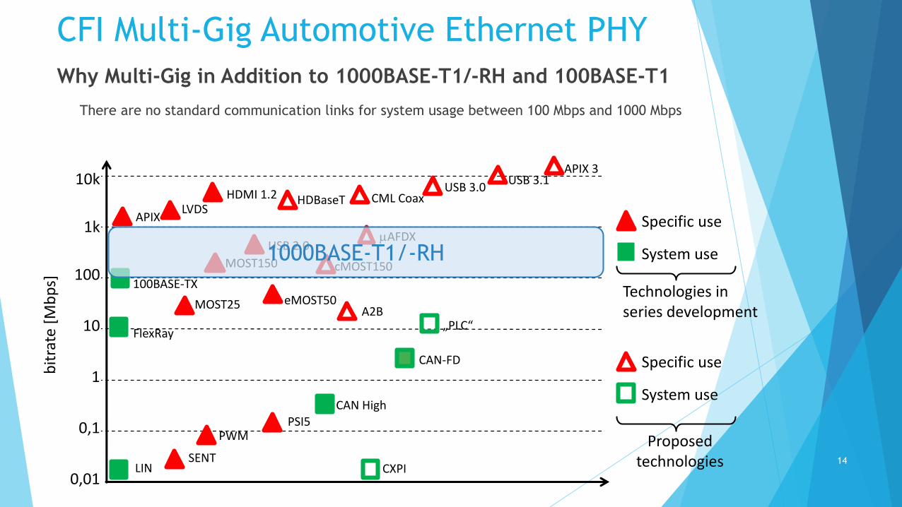
Why Multi-Gig in Addition to 1000BASE-T1/-RH and 100BASE-T1
1000BASE-T1/-RH
There are no standard communication links for system usage between 100 Mbps and 1000 Mbps
14

CFI Multi-Gig Automotive Ethernet PHY
10k
1k
100
10
1
0,1
0,01
bit
rate
[M
bp
s]
APIX 3
CML CoaxHDBaseTLVDS
USB 3.0USB 3.1
HDMI 1.2
APIX
USB 2.0 mAFDX
MOST150 cMOST150
MOST25
100BASE-TX
A2B„PLC“
eMOST50
FlexRay
LIN
PSI5
CAN-FD
SENT
PWM
CXPI
CAN High
Specific use
System use
Specific use
System use
Proposed technologies
Technologies in series development
Why Multi-Gig in Addition to 1000BASE-T1/-RH and 100BASE-T1
Multi-Gig Automotive Ethernet
There are no standard communication links for system usage above 1000 Mbps
There are many proprietary communication links above 1000 Mbps
A standard link (or links) is needed for this space
15

CFI Multi-Gig Automotive Ethernet PHY
Why Multi-Gig in Addition to 1000BASE-T1/-RH and 100BASE-T1
This follows the typical Ethernet PHY development schedule.
1
10
100
1000
10000
100000
1000000
1985 1990 1995 2000 2005 2010 2015 2020 2025
Data
rate
[M
bps]
Year of IEEE standard completion
Development of Ethernet Speed Grades
BASE-T
Fiber
Automotive
16

CFI Multi-Gig Automotive Ethernet PHY
Multi-Gig Data Transmission Links in Automotive Today
LVDS / CML
APIX
USB
HDMI
Drawbacks of these links
Point-to-point with no automatic relay systems
Additional processing power to retransmit
Difficult to coordinate timing
Proprietary solutions that make adding / changing devices difficult
High cable cost (shielding and application specific cables and connectors)
Why Multi-Gig in Addition to 1000BASE-T1/-RH and 100BASE-T1
17

CFI Multi-Gig Automotive Ethernet PHY
Why Multi-Gig in Addition to 1000BASE-T1/-RH and 100BASE-T1
Use Cases
Sharing camera data
4K and 8K shared display data
Connectivity: LTE 4G/5G, transport of 802.11ac
Connecting 1000BASE-T1/-RH switches
Diagnosis (port mirroring of multiple 1000BASE-T1/-RH links)
Scalability within a network
100BASE-T1 may be sufficient for collision warning
1000BASE-T1/-RH may be sufficient for collision avoidance
xGig (Multi-Gig) required for advanced driver assistance
Switch with 100M/1000M/xGig capability
18

CFI Multi-Gig Automotive Ethernet PHY
Use Cases
Cameras
• 4K Cameras at 60 fps – 6 to 8 Gbps
• Short propagation delay (< 20 ms) doesn’t allow for compression
Data Sharing
• Aggregation of multiple 1 Gbps links requires xGbps links
Displays
• 4K/8K displays will start appearing in vehicles
Data Recorder
• Significant amount of raw data may need to be saved to reconstruct incidents
19

CFI Multi-Gig Automotive Ethernet PHY
How many Multi-Gig
Automotive applications are very cost sensitive
There is always a need for more (speed and/or bandwidth)
Long cycle times require ability to upgrade without complete redesign,
backward compatibility
Don’t want to pay for more than required
Prefer designs that allow components to be added on an “as needed” basis
20

CFI Multi-Gig Automotive Ethernet PHY
ECU A
ECU A’’ECU A’
1G
2xG
100M
xG
Data
Record
Sensors
Redundancy for data acquisition
Redundancy and data sharing for computing platform ECUs (number crunchers)
4K/8K
4K/8K
4K/8K Displays
21

CFI Multi-Gig Automotive Ethernet PHYIEEE 802 Automotive Ethernet Eco-System
IEEE 802.3 for Diagnostics and Flashing
S 100BASE-TX
IEEE 802.3 for In-vehicle communication
S 802.3bp 1000BASE-T1 / RTPGE
S 802.3br Interspersing Express
T 802.3bu PoDL
T 802.3bv Gigabit over Plastic Optical Fiber (GEPoF)
S 802.3bw 100BASE-T1 / 1TPCE
C 10 Mbps for Automotive
C Multi-GE for Automotive
IEEE 802.1 Data Link Layer
S Audio Video Bridging
802.1 BA, 802.1 AS*, 802.1 Qat*, 802.1 Qav
T Time Sensitive Networks
802.1AS-Rev, 802.1CB, 802.1Qcc, 802.1Qci,
802.1 Qbu, 802.1 Qbv, 802.1 Qca, 802.1Qcr
T Security – 802.1AEcg I= Idea; C = CFI; T = TaskForce; S = Standard
Something is missing!
22

CFI Multi-Gig Automotive Ethernet PHY
Why Now?
Typical Automotive Ethernet PHY IEEE Timing
t0 – Idea for CFI.
t1 – CFI approved. Start to work on PAR Components.
t2 – PAR approved. Start TF meetings and select technology components.
t3 – D1.0 complete. Refine specification.
t4 – D2.0 complete. WG ballot begins.
t5 – D3.0 complete. Sponsor ballot begins.
t6 – Sponsor ballot complete.
t7 – Completed specification available.
t0 t1 t2 t3 t4 t5 t6t7
Year A Year B Year C Year D
23
CFI Multi-Gig Automotive Ethernet PHY
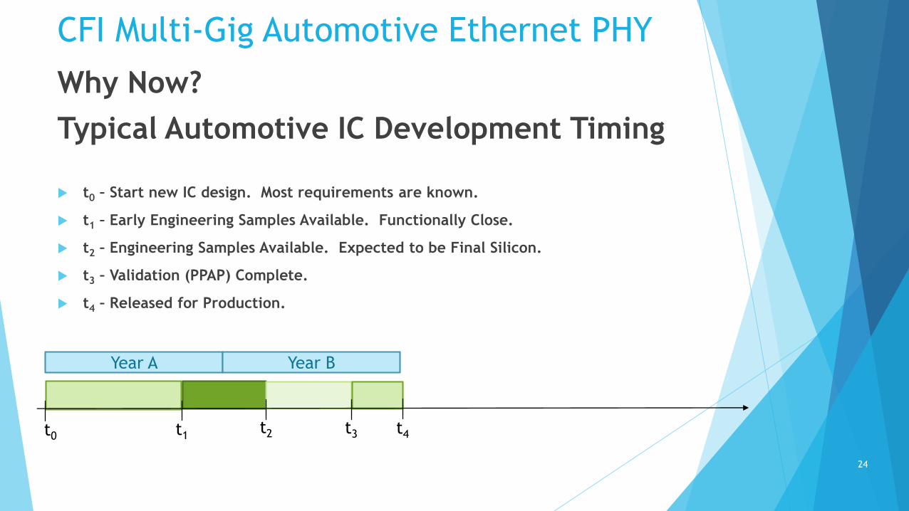
Why Now?
Typical Automotive IC Development Timing
t0 – Start new IC design. Most requirements are known.
t1 – Early Engineering Samples Available. Functionally Close.
t2 – Engineering Samples Available. Expected to be Final Silicon.
t3 – Validation (PPAP) Complete.
t4 – Released for Production.
t0 t1t2 t3 t4
Year A Year B
24

CFI Multi-Gig Automotive Ethernet PHY
Why Now? - Typical Automotive Architecture
Development Timing
t0 – Decision to create a new Architecture, n. Determine what functions should be
included.
t1 – Investigate available technologies. Verify proposed technologies are viable
through demonstrations.
t2 – Decide on technologies to be included. Kick-off ECU development. Window
closed to consider new technologies.
t3 – Decision to create next new Architecture, n+1
t0 t1 t2t3
Year A Year B Year C Year D
25

CFI Multi-Gig Automotive Ethernet PHYWhy Now
Typical Automotive ECU Development Timing
t0 – Start of new ECU (RFQ). Expect that at least Early Samples of PHYs are available.
t1 – Tier 1 has been selected.
t2 – ECU Mule bench delivery with PHY included. Does not have to be production part or package.
t3 – Development ECU available to perform validation testing. Production PHY is required; however, supplier PPAP does not have to be complete.
t4 – Validation complete on Development ECU.
t5 – Production ECU available.
t6 – Validation complete on Production ECU.
t7 – Start of Vehicle Production (SOP).
t0 t1 t2 t3 t4 t5 t6 t7
Year A Year B Year C Year D
26

CFI Multi-Gig Automotive Ethernet PHYWhy Now?
Total Automotive Ethernet PHY Development from Concept to Production
Year 1 Year 2 Year 3 Year 4 Year 5 Year 6 Year 7
Best Case Scenario
PHY Development starts with WG ballot
EES available just in time for new Architecture consideration
Vehicle production starts just over 7 years from initial idea
SOP
27
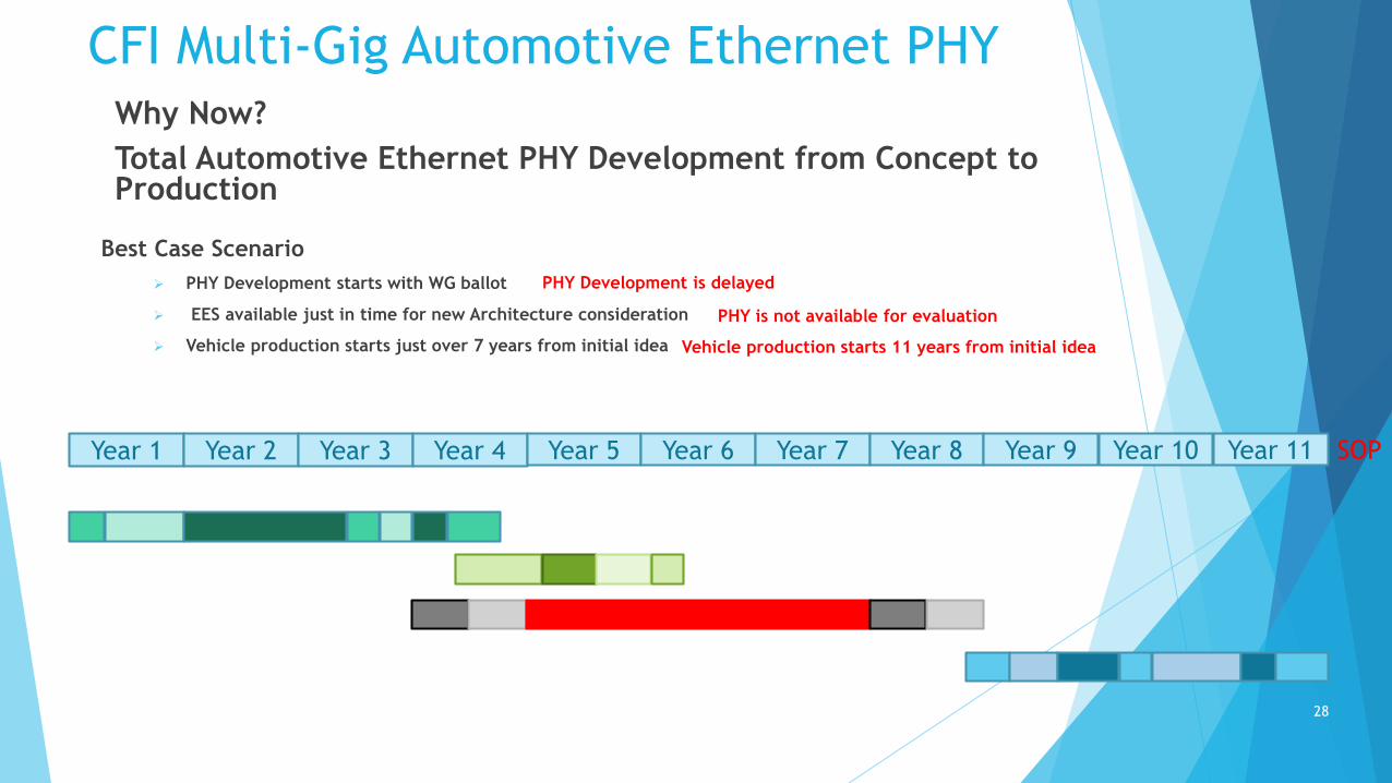
CFI Multi-Gig Automotive Ethernet PHYWhy Now?
Total Automotive Ethernet PHY Development from Concept to Production
Year 1 Year 2 Year 3 Year 4 Year 5 Year 6 Year 7 Year 8 Year 9
Best Case Scenario
PHY Development starts with WG ballot
EES available just in time for new Architecture consideration
Vehicle production starts just over 7 years from initial idea
PHY Development is delayed
Year 10 Year 11
Vehicle production starts 11 years from initial idea
SOP
PHY is not available for evaluation
28

CFI Multi-Gig Automotive Ethernet PHY
Automotive Market Potential
Camera Connectivity Forecast
(Distance Warning, Parking, Blindspot, Nightvision,...)
0
20,000
40,000
60,000
80,000
100,000
120,000
2015 2016 2017 2018 2019 2020 2021
Analog LVDS Ethernet
Units
in tsd
Display Connectivity Forecast(Headunit, Seperate, HUD,...)
0
10,000
20,000
30,000
40,000
50,000
60,000
70,000
80,000
90,000
100,000
2015 2016 2017 2018 2019 2020 2021
Analog LVDS EthernetUnits
in tsd
Data provided by29

CFI Multi-Gig Automotive Ethernet PHY Forecast from 100 BASE-T1 CFI
Forecast from 2014 CFI for 1TPCE
For RTPGE CFI we forecasted 270 million Ethernet ports by 2019/20
We were wrong, sorry!
We now assume about 400 million ports
Some numbers
In 2019 the automotive industry will produce 117 million vehicles
Up to 35 ports (20 avg.) in premium class vehicles and 20 (8 avg.) in medium class vehicles that have Ethernet
Ethernet increases creativity for new applications
Ethernet provides an infrastructure for automotive innovations
30