cfp-cb-1/2/3/4 operating instructions and specifications ... · cfp-cb-1, cfp-cb-2, cfp-cb-3, and...
TRANSCRIPT
FIELDPOINT™ OPERATING INSTRUCTIONS AND SPECIFICATIONS
cFP-CB-1/2/3/4Compact FieldPoint Connector Blocks
These operating instructions describe how to install and use the cFP-CB-1, cFP-CB-2, cFP-CB-3, and cFP-CB-4 (referred to inclusively in this manual as the cFP-CB-x).
FeaturesThe cFP-CB-x Compact FieldPoint connector blocks have the following features:
• Designed for general-purpose and hazardous-voltage operation with all Compact FieldPoint I/O modules (cFP-CB-1 and cFP-CB-2)
• Isothermal construction minimizes temperature gradients for use with thermocouples (cFP-CB-3)
• Mounting on a cFP-BP-x or cFP-180x Compact FieldPoint backplane
• Up to 36 terminals
• Tie-wrap anchors for wires (cFP-CB-1 and cFP-CB-3)
• Front-panel access to terminals (cFP-CB-2 and cFP-CB-4)
• Removable front-mounted connectors (cFP-CB-2 and cFP-CB-4)
• Spring terminals or screw terminals available
• V and C terminals for voltage supply and common connections
• –40 to 70 °C operation
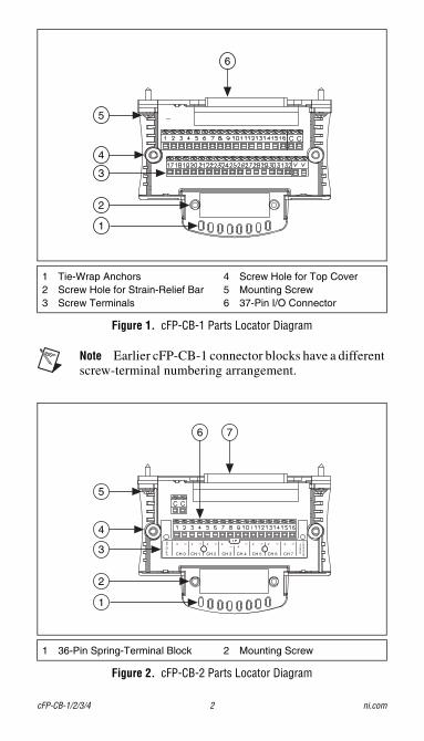
Figure 1. cFP-CB-1 Parts Locator Diagram
Note Earlier cFP-CB-1 connector blocks have a different screw-terminal numbering arrangement.
Figure 2. cFP-CB-2 Parts Locator Diagram
1 Tie-Wrap Anchors2 Screw Hole for Strain-Relief Bar3 Screw Terminals
4 Screw Hole for Top Cover5 Mounting Screw6 37-Pin I/O Connector
1 36-Pin Spring-Terminal Block 2 Mounting Screw
C C
6
5
4
3
2
1
C C
cFP
-TC
-120 + –
CH 0
+ –
CH 1
+ –
CH 2
+
CH 3
–
CH 4
+ –
CH 5
+ –
CH 6
+ –
CH 7 TE
RM
INA
L
AS
SIG
NM
EN
TS
– +
76
5
4
3
2
1
cFP-CB-1/2/3/4 2 ni.com
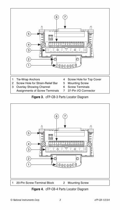
Figure 3. cFP-CB-3 Parts Locator Diagram
Figure 4. cFP-CB-4 Parts Locator Diagram
1 Tie-Wrap Anchors2 Screw Hole for Strain-Relief Bar3 Overlay Showing Channel
Assignments of Screw Terminals
4 Screw Hole for Top Cover5 Mounting Screw6 Screw Terminals7 37-Pin I/O Connector
1 20-Pin Screw-Terminal Block 2 Mounting Screw
C C
cFP
-TC
-120 + –
CH 0
+ –
CH 1
+ –
CH 2
+
CH 3
–
CH 4
+ –
CH 5
+ –
CH 6
+ –
CH 7 TE
RM
INA
L
AS
SIG
NM
EN
TS
– +
76
5
4
3
2
1
C C
cFP
-TC
-120 + –
CH 0
+ –
CH 1
+ –
CH 2
+
CH 3
–
CH 4
+ –
CH 5
+ –
CH 6
+ –
CH 7 TE
RM
INA
L
AS
SIG
NM
EN
TS
– +
76
5
4
3
2
1
© National Instruments Corp. 3 cFP-CB-1/2/3/4
Wiring to the Connector BlockRefer to the I/O module operating instructions for information about wiring configurations, including detailed wiring diagrams and fuse recommendations.
Note To protect the FieldPoint system and connected devices, install appropriate external fuses on all terminals. Refer to the Specifications section for the current limits of the cFP-CB-x terminals.
Note The V terminals are internally connected to each other and the C terminals are internally connected to each other.
Caution Ensure that hazardous voltage wiring is performed only by qualified personnel adhering to local electrical standards.
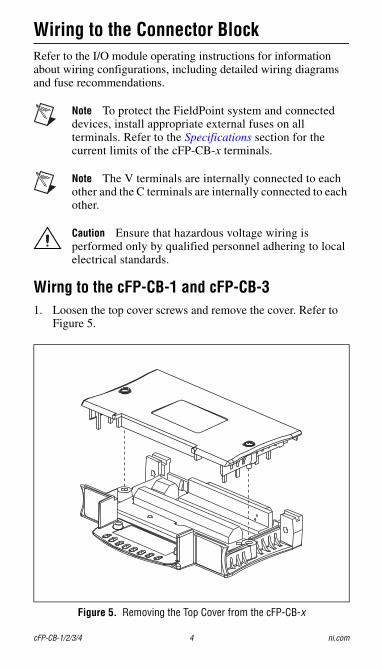
Wirng to the cFP-CB-1 and cFP-CB-31. Loosen the top cover screws and remove the cover. Refer to
Figure 5.
Figure 5. Removing the Top Cover from the cFP-CB-x
cFP-CB-1/2/3/4 4 ni.com
2. Verify that there are no cuts in the wire insulation that can cause a safety hazard.
3. Strip 6 mm (0.24 in.) of insulation from the ends of the wires.
4. Insert the entire stripped ends of the wires into the appropriate screw terminals. Do not allow any bare wire to show outside the screw terminals.
5. Using a 1/8 in. flathead screwdriver, tighten the screw terminals to 0.5–0.6 N ⋅ m (4.4–5.3 lb ⋅ in.) of torque.
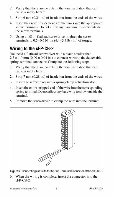
Wiring to the cFP-CB-2You need a flathead screwdriver with a blade smaller than 2.3 × 1.0 mm (0.09 × 0.04 in.) to connect wires to the detachable spring-terminal connector. Complete the following steps:
1. Verify that there are no cuts in the wire insulation that can cause a safety hazard.
2. Strip 7 mm (0.28 in.) of insulation from the ends of the wires.
3. Insert the screwdriver into a spring clamp activation slot.
4. Insert the entire stripped end of the wire into the corresponding spring terminal. Do not allow any bare wire to show outside the terminal.
5. Remove the screwdriver to clamp the wire into the terminal.
Figure 6. Connecting a Wire to the Spring-Terminal Connector of the cFP-CB-2
6. When the wiring is complete, insert the connector into the cFP-CB-2.
© National Instruments Corp. 5 cFP-CB-1/2/3/4
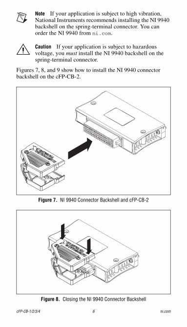
Note If your application is subject to high vibration, National Instruments recommends installing the NI 9940 backshell on the spring-terminal connector. You can order the NI 9940 from ni.com.
Caution If your application is subject to hazardous voltage, you must install the NI 9940 backshell on the spring-terminal connector.
Figures 7, 8, and 9 show how to install the NI 9940 connector backshell on the cFP-CB-2.
Figure 7. NI 9940 Connector Backshell and cFP-CB-2
Figure 8. Closing the NI 9940 Connector Backshell
cFP-CB-1/2/3/4 6 ni.com
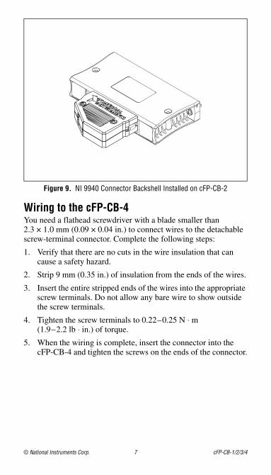
Figure 9. NI 9940 Connector Backshell Installed on cFP-CB-2
Wiring to the cFP-CB-4You need a flathead screwdriver with a blade smaller than 2.3 × 1.0 mm (0.09 × 0.04 in.) to connect wires to the detachable screw-terminal connector. Complete the following steps:
1. Verify that there are no cuts in the wire insulation that can cause a safety hazard.
2. Strip 9 mm (0.35 in.) of insulation from the ends of the wires.
3. Insert the entire stripped ends of the wires into the appropriate screw terminals. Do not allow any bare wire to show outside the screw terminals.
4. Tighten the screw terminals to 0.22–0.25 N ⋅ m (1.9–2.2 lb ⋅ in.) of torque.
5. When the wiring is complete, insert the connector into the cFP-CB-4 and tighten the screws on the ends of the connector.
© National Instruments Corp. 7 cFP-CB-1/2/3/4
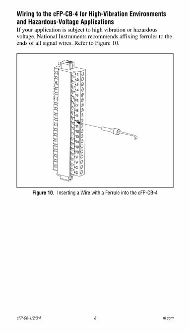
Wiring to the cFP-CB-4 for High-Vibration Environments and Hazardous-Voltage ApplicationsIf your application is subject to high vibration or hazardous voltage, National Instruments recommends affixing ferrules to the ends of all signal wires. Refer to Figure 10.
Figure 10. Inserting a Wire with a Ferrule into the cFP-CB-4
cFP-CB-1/2/3/4 8 ni.com
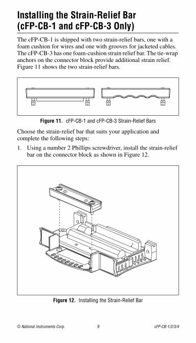
Installing the Strain-Relief Bar (cFP-CB-1 and cFP-CB-3 Only)The cFP-CB-1 is shipped with two strain-relief bars, one with a foam cushion for wires and one with grooves for jacketed cables. The cFP-CB-3 has one foam-cushion strain relief bar. The tie-wrap anchors on the connector block provide additional strain relief. Figure 11 shows the two strain-relief bars.
Figure 11. cFP-CB-1 and cFP-CB-3 Strain-Relief Bars
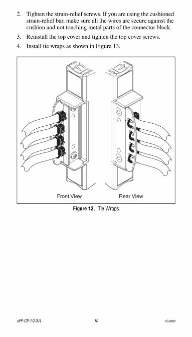
Choose the strain-relief bar that suits your application and complete the following steps:
1. Using a number 2 Phillips screwdriver, install the strain-relief bar on the connector block as shown in Figure 12.
Figure 12. Installing the Strain-Relief Bar
© National Instruments Corp. 9 cFP-CB-1/2/3/4
2. Tighten the strain-relief screws. If you are using the cushioned strain-relief bar, make sure all the wires are secure against the cushion and not touching metal parts of the connector block.
3. Reinstall the top cover and tighten the top cover screws.
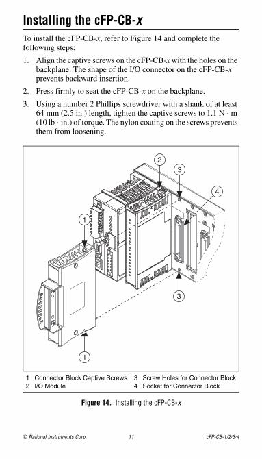
4. Install tie wraps as shown in Figure 13.
Figure 13. Tie Wraps
Front View Rear View
cFP-CB-1/2/3/4 10 ni.com
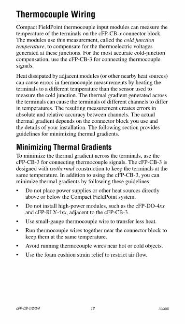
Installing the cFP-CB-xTo install the cFP-CB-x, refer to Figure 14 and complete the following steps:
1. Align the captive screws on the cFP-CB-x with the holes on the backplane. The shape of the I/O connector on the cFP-CB-x prevents backward insertion.
2. Press firmly to seat the cFP-CB-x on the backplane.
3. Using a number 2 Phillips screwdriver with a shank of at least 64 mm (2.5 in.) length, tighten the captive screws to 1.1 N ⋅ m (10 lb ⋅ in.) of torque. The nylon coating on the screws prevents them from loosening.
Figure 14. Installing the cFP-CB-x
1 Connector Block Captive Screws2 I/O Module
3 Screw Holes for Connector Block4 Socket for Connector Block
3
4
3
2
1
1
© National Instruments Corp. 11 cFP-CB-1/2/3/4
Thermocouple WiringCompact FieldPoint thermocouple input modules can measure the temperature of the terminals on the cFP-CB-x connector block. The modules use this measurement, called the cold junction temperature, to compensate for the thermoelectric voltages generated at these junctions. For the most accurate cold-junction compensation, use the cFP-CB-3 for connecting thermocouple signals.
Heat dissipated by adjacent modules (or other nearby heat sources) can cause errors in thermocouple measurements by heating the terminals to a different temperature than the sensor used to measure the cold junction. The thermal gradient generated across the terminals can cause the terminals of different channels to differ in temperatures. The resulting measurement creates errors in absolute and relative accuracy between channels. The actual thermal gradient depends on the connector block you use and the details of your installation. The following section provides guidelines for minimizing thermal gradients.
Minimizing Thermal GradientsTo minimize the thermal gradient across the terminals, use the cFP-CB-3 for connecting thermocouple signals. The cFP-CB-3 is designed with isothermal construction to keep the terminals at the same temperature. In addition to using the cFP-CB-3, you can minimize thermal gradients by following these guidelines:
• Do not place power supplies or other heat sources directly above or below the Compact FieldPoint system.
• Do not install high-power modules, such as the cFP-DO-4xx and cFP-RLY-4xx, adjacent to the cFP-CB-3.
• Use small-gauge thermocouple wire to transfer less heat.
• Run thermocouple wires together near the connector block to keep them at the same temperature.
• Avoid running thermocouple wires near hot or cold objects.
• Use the foam cushion strain relief to restrict air flow.
cFP-CB-1/2/3/4 12 ni.com
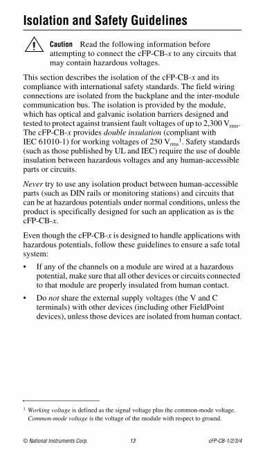
Isolation and Safety Guidelines
Caution Read the following information before attempting to connect the cFP-CB-x to any circuits that may contain hazardous voltages.
This section describes the isolation of the cFP-CB-x and its compliance with international safety standards. The field wiring connections are isolated from the backplane and the inter-module communication bus. The isolation is provided by the module, which has optical and galvanic isolation barriers designed and tested to protect against transient fault voltages of up to 2,300 Vrms. The cFP-CB-x provides double insulation (compliant with IEC 61010-1) for working voltages of 250 Vrms
1. Safety standards (such as those published by UL and IEC) require the use of double insulation between hazardous voltages and any human-accessible parts or circuits.
Never try to use any isolation product between human-accessible parts (such as DIN rails or monitoring stations) and circuits that can be at hazardous potentials under normal conditions, unless the product is specifically designed for such an application as is the cFP-CB-x.
Even though the cFP-CB-x is designed to handle applications with hazardous potentials, follow these guidelines to ensure a safe total system:
• If any of the channels on a module are wired at a hazardous potential, make sure that all other devices or circuits connected to that module are properly insulated from human contact.
• Do not share the external supply voltages (the V and C terminals) with other devices (including other FieldPoint devices), unless those devices are isolated from human contact.
1 Working voltage is defined as the signal voltage plus the common-mode voltage. Common-mode voltage is the voltage of the module with respect to ground.
© National Instruments Corp. 13 cFP-CB-1/2/3/4

• You must connect the protective earth (PE) ground terminal on the cFP-BP-x or cFP-180x backplane to the system safety ground. The backplane PE ground terminal has the following symbol stamped beside it: . Connect the backplane PE ground terminal to the system safety ground using 14 AWG (1.6 mm) wire with a ring lug. Use the 5/16 in. panhead screw shipped with the backplane to secure the ring lug to the backplane PE ground terminal.
• As with any hazardous voltage wiring, make sure that all wiring and connections meet applicable electrical codes and commonsense practices. Mount the backplane in an area, position, or cabinet that prevents accidental or unauthorized access to wiring that carries hazardous voltages.
• The isolation of the cFP-CB-x is certified as double-insulated for working voltages of up to 250 Vrms.
• Operate the cFP-CB-x only at or below Pollution Degree 2. Pollution Degree 2 means that only nonconductive pollution occurs in most cases. Occasionally, however, a temporary conductivity caused by condensation must be expected.
• Do not operate FieldPoint products in an explosive atmosphere or where there may be flammable gases or fumes. If you need to operate FieldPoint products in such an environment, the FieldPoint products must be in a suitably rated enclosure.
• Operate the cFP-CB-x at or below Measurement Category II. Measurement Category II is for measurements performed on circuits directly connected to the electrical distribution system. This category refers to local-level distribution, such as that provided by a standard wall outlet.
cFP-CB-1/2/3/4 14 ni.com
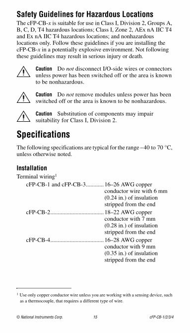
Safety Guidelines for Hazardous LocationsThe cFP-CB-x is suitable for use in Class I, Division 2, Groups A, B, C, D, T4 hazardous locations; Class I, Zone 2, AEx nA IIC T4 and Ex nA IIC T4 hazardous locations; and nonhazardous locations only. Follow these guidelines if you are installing the cFP-CB-x in a potentially explosive environment. Not following these guidelines may result in serious injury or death.
Caution Do not disconnect I/O-side wires or connectors unless power has been switched off or the area is known to be nonhazardous.
Caution Do not remove modules unless power has been switched off or the area is known to be nonhazardous.
Caution Substitution of components may impair suitability for Class I, Division 2.
SpecificationsThe following specifications are typical for the range –40 to 70 °C, unless otherwise noted.
InstallationTerminal wiring1
cFP-CB-1 and cFP-CB-3............ 16–26 AWG copper conductor wire with 6 mm (0.24 in.) of insulation stripped from the end
cFP-CB-2.................................... 18–22 AWG copper conductor with 7 mm (0.28 in.) of insulation stripped from the end
cFP-CB-4.................................... 16–28 AWG copper conductor with 9 mm (0.35 in.) of insulation stripped from the end
1 Use only copper conductor wire unless you are working with a sensing device, such as a thermocouple, that requires a different type of wire.
© National Instruments Corp. 15 cFP-CB-1/2/3/4
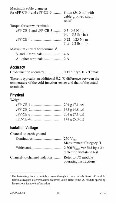
Maximum cable diameterfor cFP-CB-1 and cFP-CB-3 ............ 8 mm (5/16 in.) with
cable-grooved strain relief
Torque for screw terminalscFP-CB-1 and cFP-CB-3............ 0.5–0.6 N ⋅ m
(4.4–5.3 lb ⋅ in.)cFP-CB-4.................................... 0.22–0.25 N ⋅ m
(1.9–2.2 lb ⋅ in.)
Maximum current for terminals1
V and C terminals....................... 4 AAll other terminals...................... 2 A
AccuracyCold-junction accuracy..................... 0.15 °C typ, 0.3 °C max
There is typically an additional 0.2 °C difference between the temperature of the cold-junction sensor and that of the actual terminals.
PhysicalWeight
cFP-CB-1.................................... 201 g (7.1 oz)cFP-CB-2.................................... 135 g (4.8 oz)cFP-CB-3.................................... 201 g (7.1 oz)cFP-CB-4.................................... 141 g (5.0 oz)
Isolation VoltageChannel-to-earth ground
Continuous ................................. 250 Vrms, Measurement Category II
Withstand.................................... 2,300 Vrms, verified by a 2 s dielectric withstand test
Channel-to-channel isolation ............Refer to I/O module operating instructions
1 Use fast-acting fuses to limit the current through screw terminals. Some I/O module terminals require a lower maximum current value. Refer to the I/O module operating instructions for more information.
cFP-CB-1/2/3/4 16 ni.com
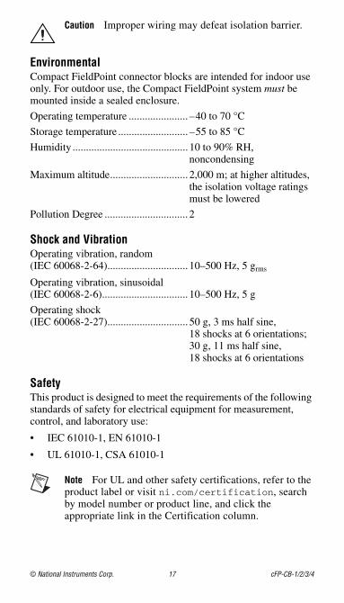
Caution Improper wiring may defeat isolation barrier.
EnvironmentalCompact FieldPoint connector blocks are intended for indoor use only. For outdoor use, the Compact FieldPoint system must be mounted inside a sealed enclosure.
Operating temperature ...................... –40 to 70 °C
Storage temperature .......................... –55 to 85 °C
Humidity ........................................... 10 to 90% RH, noncondensing
Maximum altitude............................. 2,000 m; at higher altitudes, the isolation voltage ratings must be lowered
Pollution Degree ............................... 2
Shock and VibrationOperating vibration, random (IEC 60068-2-64).............................. 10–500 Hz, 5 grms
Operating vibration, sinusoidal (IEC 60068-2-6)................................ 10–500 Hz, 5 g
Operating shock (IEC 60068-2-27).............................. 50 g, 3 ms half sine,
18 shocks at 6 orientations;30 g, 11 ms half sine, 18 shocks at 6 orientations
SafetyThis product is designed to meet the requirements of the following standards of safety for electrical equipment for measurement, control, and laboratory use:
• IEC 61010-1, EN 61010-1
• UL 61010-1, CSA 61010-1
Note For UL and other safety certifications, refer to the product label or visit ni.com/certification, search by model number or product line, and click the appropriate link in the Certification column.
© National Instruments Corp. 17 cFP-CB-1/2/3/4
Electromagnetic CompatibilityThis product is designed to meet the requirements of the following standards of EMC for electrical equipment for measurement, control, and laboratory use:
• EN 61326 EMC requirements; Industrial Immunity
• EN 55011 Emissions; Group 1, Class A
• CE, C-Tick, ICES, and FCC Part 15 Emissions; Class A
Note For For EMC compliance, operate this device according to product documentation.
CE ComplianceThis product meets the essential requirements of applicable European Directives, as amended for CE marking, as follows:
• 2006/95/EC; Low-Voltage Directive (safety)
• 2004/108/EC; Electromagnetic Compatibility Directive (EMC)
Note Refer to the Declaration of Conformity (DoC) for this product for any additional regulatory compliance information. To obtain the DoC for this product, visit ni.com/certification, search by model number or product line, and click the appropriate link in the Certification column.
cFP-CB-1/2/3/4 18 ni.com

Environmental ManagementNI is committed to designing and manufacturing products in an environmentally responsible manner. NI recognizes that eliminating certain hazardous substances from our products is beneficial not only to the environment but also to NI customers.
For additional environmental information, refer to the NI and the Environment Web page at ni.com/environment. This page contains the environmental regulations and directives with which NI complies, as well as other environmental information not included in this document.
Waste Electrical and Electronic Equipment (WEEE)
EU Customers At the end of their life cycle, all products must be sent to a WEEE recycling center. For more information about WEEE recycling centers and National Instruments WEEE initiatives, visit ni.com/environment/weee.
RoHSNational Instruments
(RoHS)National Instruments RoHSni.com/environment/rohs_china (For information about China RoHS compliance, go to ni.com/environment/rohs_china.)
© National Instruments Corp. 19 cFP-CB-1/2/3/4
Where to Go for SupportFor more information about setting up the Compact FieldPoint system, refer to these National Instruments documents:
• Compact FieldPoint controller user manual
• Compact FieldPoint I/O module operating instructions
Go to ni.com/support for the most current manuals, examples, and troubleshooting information.
For telephone support in the United States, create your service request at ni.com/ask and follow the calling instructions or dial 512 795 8248. For telephone support outside the United States, contact your local branch office:
Australia 1800 300 800, Austria 43 662 457990-0, Belgium 32 (0) 2 757 0020, Brazil 55 11 3262 3599, Canada 800 433 3488, China 86 21 5050 9800, Czech Republic 420 224 235 774, Denmark 45 45 76 26 00, Finland 358 (0) 9 725 72511, France 01 57 66 24 24, Germany 49 89 7413130, India 91 80 41190000, Israel 972 3 6393737, Italy 39 02 41309277, Japan 0120-527196, Korea 82 02 3451 3400, Lebanon 961 (0) 1 33 28 28, Malaysia 1800 887710, Mexico 01 800 010 0793, Netherlands 31 (0) 348 433 466, New Zealand 0800 553 322, Norway 47 (0) 66 90 76 60, Poland 48 22 3390150, Portugal 351 210 311 210, Russia 7 495 783 6851, Singapore 1800 226 5886, Slovenia 386 3 425 42 00, South Africa 27 0 11 805 8197, Spain 34 91 640 0085, Sweden 46 (0) 8 587 895 00, Switzerland 41 56 2005151, Taiwan 886 02 2377 2222, Thailand 662 278 6777, Turkey 90 212 279 3031, United Kingdom 44 (0) 1635 523545
© 2002–2007 National Instruments Corp. All rights reserved.
373322C-01 Dec07
National Instruments, NI, ni.com, and LabVIEW are trademarks of National Instruments Corporation. Refer to the Terms of Use section on ni.com/legal for more information about National Instruments trademarks. Other product and company names mentioned herein are trademarks or trade names of their respective companies. For patents covering National Instruments products, refer to the appropriate location: Help»Patents in your software, the patents.txt file on your CD, or ni.com/patents.