cfw500 - variable speed drive - weg france moteur
TRANSCRIPT

CFW500 - VARIABLESPEED DRIVEHigh performance and reliability toimprove your production process
Motors | Automation | Energy | Transmission & Distribution | Coatings


Summary
CFW500 Variable Speed Drive
Introduction 04
Flexibility and Performance 07
Simplified Programming and Operation 06
Connectivity 08
Features 09
Embedded Safety Functions 10
Pump Genius 11
Applications 12
Coding 13
Specification 14
Accessories 19
Dimensions and Weights 21
Standards 22
Technical Specifications 23
Block Diagram of IP20 / NEMA Type 1 Version 24
Block Diagram of IP66 / NEMA Type 4x Version 25

Variable Speed Drive - CFW5004
Machinery Drive
With modern design, the variable speed drive CFW500 is a high performance VSD for applications that require speed and torque control of three-phase induction motors. The equipment has sensorless vector control, closed loop vector control or scalar V/f. It also has SoftPLC, which adds PLC (programmable logic controller) functions, safety functions (STO and SS1) - making easier to comply the machine and application safety requirements, Pump Genius, which adds dedicated functions for pumping systems and selectable plug-in modules, that provide a flexible and optimized solution for any application.
Flexible
Robust
High performance Wide power range and high overload capacity
Assembly options
Version with IP66 / NEMA type 4x
High performance control methods
Optional version with integrated safety functions
Connectivity
Endless possibilities
ReliableProtection against ground fault, short circuit,
over temperature and others
WEG Quality
Innovative
SoftPLC - built-in PLC functionalities
Free programming softwares
Advanced resources and functions
Internal RFI filter to reduce high-frequency electromagnetic interference

Variable Speed Drive - CFW500 5
Integrated STO (Safe Torque Off) and SS1 (Safe Stop 1) fulfils requirements for safety performance SIL 3 / PL e, according to
IEC 61800-5-2, EN ISO 13849-1, EN 62061, IEC 61508 and IEC 60204-1
Provides machine builders a cost-effective solution to design protective measures to reduce the risk from unexpected and
hazardous movement in industrial machines
Surface or DIN rail mounting, including side-by-side installation
Pump Genius software
Complete protection against contact with internal live parts, avoiding the entrance of dust or water coming from jets
USB and fieldbus communication modules for the most used industrial networks, like CANopen, DeviceNet,
Profibus-DP, EtherNet/IP, PROFINET IO or Modbus-RTUFull integration with process network
Saves space and cabling, reducing installation costs
Dedicated functions ideal for pumping systems
The high protection degree dispenses the panel,reducing installation costs
Models from 1,0 to 105 A (0,25 kW / 0,33 HP to 55 kW / 75 HP) at supply voltages 200-240, 380-480 or 500-600 V
Sensorless or closed loop vector control, VVW or Scalar V/f and permanent magnet motor control: VVW PM
Permits the CFW500 to be used in a large variety of applications, improving their overall performance
100% of the VSDs are tested at the factory under full load and maximum temperature
It prevents damage to the inverter which can be caused by adverse situations, normally external factors.
Conformal Coating (Tropicalization) as standard, class 3C2 according to IEC 60721-3-3 and 3C3 as an option, to protect
against corrosive gases in harsh environments
The VSD, motor and application can work in an interactive way, because it is possible to make customized logic and applications.
Ideal for machinery manufacturer
High reliability
VSD lifetime is extended
WLP, WPS and SuperDrive G2 softwares available at www.weg.net
Certifications

www.weg.net
6
Simplified Programming and Operation
CFW500 status
Main display
Bar forvariable monitoring
Secondary display
Unit of measurement (value of the main
display)
Menu to select the group of parameters
Soft keys function
Remote Operating Interface (HMI)Solutions for machine consoles and panels.
CFW500-HMIRAccessory
Note: the operating interface (HMI) of the CFW500 is not removable. For remote operation of the HMI, use the CFW500-HMIR accessory, according to the accessory table on page 19.
Variable Speed Drive - CFW500
J Monitoring, setting of all parameters as well as commands J Up to three parameters indication on the display, according to user selection J Oriented start-up and grouped parameters
Operating Interface (HMI)

www.weg.net
7
Flexibility and Performance
The CFW500 has a modern design and it can be selected according to the application requirements, providing flexibility with excellent performance. The VSD gives the user the possibility to choose the plug-in module that best fits his application, or to use the standard version, that comes with the CFW500-IOS plug-in module. All plug-in modules comes with one RS485 port as standard.The installation of the CFW500 is simple and its configuration and operation is intuitive with the navigation menus of the operating interface (HMI) with built-in LCD display. By using the flash memory module, it is possible to download the existing setting from one CFW500 to other units without powering them up.
Plug-In ModulesSelectable according to the application.
Easily Removable FanThe quick change system ensures simple and fast fan maintenance.
Flash Memory Module (CFW500-MMF Accessory) Download/Upload the settings to other CFW500 units without the need to power them up.
Conformal CoatingImproved 3C2 class of coating on the internal circuits of all versions and extra 3C3 Class coating (optional) according to IEC 60721-3-3 ensures improved protection in environments with corrosive chemicals.
SoftPLCIt is a software resource added to the CFW500 which allows the user to implement and debug logic projects equivalent to a small PLC (Programmable Logic Controller), customizing and integrating the CFW500 to the application. The free WPS programming software is available at: www.weg.net.
Variable Speed Drive - CFW500
www.weg.net
Variable Speed Drive - CFW5008
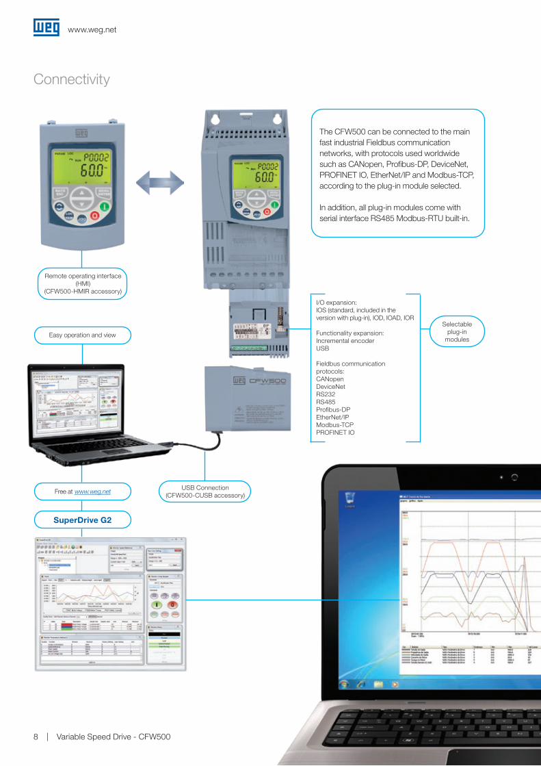
Free at www.weg.netUSB Connection
(CFW500-CUSB accessory)
Easy operation and view
SuperDrive G2
I/O expansion:IOS (standard, included in the version with plug-in), IOD, IOAD, IOR
Functionality expansion:Incremental encoderUSB
Fieldbus communication protocols:CANopenDeviceNet RS232 RS485Profibus-DP EtherNet/IPModbus-TCP PROFINET IO
Selectable plug-in
modules
Remote operating interface (HMI)
(CFW500-HMIR accessory)
Connectivity
The CFW500 can be connected to the mainfast industrial Fieldbus communicationnetworks, with protocols used worldwidesuch as CANopen, Profibus-DP, DeviceNet, PROFINET IO, EtherNet/IP and Modbus-TCP, according to the plug-in module selected.
In addition, all plug-in modules come withserial interface RS485 Modbus-RTU built-in.

www.weg.net
Variable Speed Drive - CFW500 9
Features
J Special engineering units (RPM, ºC, Nm, mA, %, kW, kWh, among others)
J Password to protect the parameters J Backup of all parameters (via SuperDrive G2 software, or plugin memory MMF)
J Possibility to save up to two different settings on the memory of the CFW500
J Setting of the switching frequency according to the application requirements
J Speed reference via electronic potentiometer J Multispeed with up to eight programmable speeds J Slip compensation J Manual or automatic torque boost (V/F scalar mode) or self-adjustment (VVW and vector modes)
J Permanent magnet motor control: VVW PM J Acceleration/deceleration ramps J “S” type ramp J DC braking J Internal dynamic braking (except frame size A) J PID controller to control processes in closed loop J Flying start / Ride-through J Sleep mode J Skip frequencies or frequency ranges function adjustable J Overload and overtemperature protection J Overcurrent protection J DC link voltage supervision J Fault log J Safety functions: STO and SS1
Using the SuperDrive G2 software, it is possible to change, monitor and view graphically the variables of the CFW500 on a personal computer.
Trend FunctionTrend charts for online monitoring of parameters and other variables within the SuperDrive G2 software.

www.weg.net
Variable Speed Drive - CFW50010
Embedded Safety Functions1)
Advantages
Safety Functions
STO (Safe Torque Off)
SS1 (Safe Stop 1)
Used to reduce risk and to guarantee the safety of personnel and environment if there is a hazardous event due to a fault in operating machines. The embedded safety functions STO and SS1 provide machine builders a cost-effective solution to design protective measures and reduce the risk from unexpected and hazardous movement in industrial machines and processes.
This function immediately switches off the drive output to the motor, disabling the supply of torque-generating energy. STO is also used to prevent an unexpected startup of machinery or for an emergency stop, fulfilling stop category 0 (IEC 60204-1).It is applicable if the motor can be brought to a standstill in a sufficiently short time by the load torque or friction or where motor coast to a stop is not relevant to safety.
This function enables motor deceleration and then, after a delay time, activates the STO function. SS1 can be used to implement a controlled stop and then removal of power, fulfilling stop category 1 according to IEC 60204-1. This function is used when, in the event of a safety related fault, the drive must stop as quickly as possible and then enter the STO state. The stopping of a drive by means of SS1 function reduces the risk of danger, eliminates the need of external safety timers, increases the productivity of a machine and allows safety clearances in a machine to be reduced. The reason is the active stopping of the drive as compared with the use of the STO function only.
J Safety functions integrated in the CFW500 drive, making easier to comply with the machine and application safety requirements
J Less components, no need for additional wiring, saving space and installation costs
J Easier installation, commissioning and maintenance J No electromechanical components, meaning faster responses and higher degree of productivity
J Due to the high safety performance level SIL3, the CFW500 with Safety module may avoid the use of external safety relays for cables and emergency pushbuttons monitoring
Note: 1) Safety Functions STO and SS1 are available in CFW500…Y2 version. It fulfils requirements for safety performance SIL 3 / PL e, according to IEC 61800-5-2, EN ISO 13849-1, EN 62061, IEC 61508 and IEC 60204-1.
Motor speed
Time
STO
Motor speed
Time
SS1-t STO
Motor speed
Time
STO
Motor speed
Time
SS1-t STO
Motor speed
Time
STO behavior
SS1 behavior
Time
STO
STOSS1-t
Motor speed

www.weg.net
Variable Speed Drive - CFW500 11
Pump Genius
Pump Genius Multipump allows driving two or more
pumps with only one inverter.
Energy SavingsThe use of the CFW500 with the Pump Genius Multipump improves the performance and provides electric energy savings.Using this solution together with WEG W22 Premium motors, and reducing the pump speed even if slightly, it is possible to reduce the electric energy consumption by approximately 15%, thus contributing to the sustainable development of the planet.
Sleep and Wake up FunctionThe sleep function keeps the pump in the standby mode when the demand or flow is below the minimum, avoiding that it runs at low speed for long periods, providing electric energy savings and increasing the lifetime of the pump. The wake up function restarts the drive automatically when the pressure falls below the set point.
Pipe Charging Function It allows lubrication and smooth initial charging of the pipes, making the pump operate at a lower preset speed for a certain time, avoiding “Water Hammers”, which may damage the piping system.
Broken Pipe AlarmPump Genius detects when the pump is consuming more electric energy than it should, by means of information on the pump load and speed, automatically generating an alarm warning of leaky pipes. In addition, with the monitoring of the system pressure, a clogging condition may be detected by configuring the maximum pressure to trigger the alarm of clogged pipe.
The Pump Genius is a customizable feature of WEG drives that enables your standard CFW500 to become dedicated for pumping systems. It ensures accurate pressure / flow control throughout the processing cycle, starting with raw water and its usage, ending on wastewater treatment. With an easy-to-use programming wizard, Pump Genius helps you to minimize downtime and maximize energy savings. Everything you need is selecting one option that best fits your application:
Note: 1) Under development. Find out more about Pump Genius visiting our website www.weg.net.
multipumpPump Genius Multiplex permits the
VSDs to control, monitor and manage the entire system on their own,
eliminating the need of external PLC.
multiplex1)
The Pump Genius Simplex software adds
ideal features to the VSD for single pump control.
simplex

www.weg.net
Variable Speed Drive - CFW50012
Applications
Extruders
Centrifugal pumps
Process dosing pumps
Conveyor belts
Granulators / palletizers
Stirrers / mixers
Roller tables
Cutting and welding machines
Rotary filters
Fans / exhausters
Dryers and rotary ovens
Winding machines / uncoiling machines

www.weg.net
Variable Speed Drive - CFW500 13
Coding1)
4 - Number of phases 9 - Disconnect switch4)
10 - Safety function5)
S Single-phase power supplyB Single or three-phase power supplyT Three-phase power supply
Blank Without disconnect switchDS With disconnect switch
Blank Without safety functionY2 With safety function (STO and SS1-t) as per EN 61800
8 - RFI filter3)
Blank Without internal RFI filterC2 With internal RFI filter - category 2C3 With internal RFI filter - category 3
11.1 - Plug-in module
11.2 - Coating for harsh environments
11 - Special hardware versions - H xx
Blank With standard plug-in module
H00 Without plug-in module
Blank Class 3C2 - Standard conformal coating
EC Class 3C3 - Extra coating
12 - Special software version - S xxBlank Standard software
Sxx Special software
5 - Rated voltage2 200-240 V4 380-480 V5 500-600 V
6 - Internal dynamic braking2)
NB Without internal dynamic braking IGBTDB With internal dynamic braking IGBT
7- Protection degree20 IP20 protection degreeN1 Cabinet type 1 protection degree66 IP66 protection degree (Type 4x)
1 - CFW500 variable speed drive2 - Size of the CFW500, according to table 1 below3 - Rated output current, according to table 1 below
1 CFW500 3 02P62 A 4 T 5 4 6 NB 7 20 8 C2 9 Y2 10 --- 11 ---
Power supply Single-phase (S) Single-phase or three-phase (B) Three-phase (T)
Voltage 200-240 V ac 200-240 V ac 200-240 V ac 380-480 V ac 500 - 600 V ac
Current
01P6 = 1.6 A02P6 = 2.6 A04P3 = 4.3 A07P0 = 7.0 A07P3 = 7.3 A10P0 = 10 A
01P6 = 1.6 A02P6 = 2.6 A04P3 = 4.3 A07P3 = 7.3 A10P0 = 10 A
07P0 = 7.0 A09P6 = 9.6 A16P0 = 16 A24P0 = 24 A28P0 = 28 A33P0 = 33 A47P0 = 47 A56P0 = 56 A
01P0 = 1.0 A01P6 = 1.6 A02P6 = 2.6 A04P3 = 4.3 A06P1 = 6.1 A02P6 = 2.6 A04P3 = 4.3 A06P5 = 6.5 A10P0 = 10 A14P0 = 14 A16P0 = 16 A24P0 = 24 A31P0 = 31 A39P0 = 39 A49P0 = 49 A77P0 = 77 A88P0 = 88 A0105 = 105 A
01P7 = 1.7 A03P0 = 3.0 A04.3 = 4.3 A07P0 = 7.0 A10P0 = 10 A12P0 = 12 A
Notes: 1) Other configurations available upon request. 2) Braking resistor not included. Braking IGBT is available as standard for the whole CFW500 line, except for frame size A of IP20 version. 3) Conducted emission level (IEC 61800-3). In order to minimize such problem, WEG variable speed drives contain common-mode capacitive filters, which are enough to avoid this type of interference in most cases. If necessary, our inverters also have radio frequency (RFI) filters to reduce even more those high-frequency electromagnetic interference signals. Item 8 of the table above shows how to select the models of internal RFI filters for the CFW500. Definitions of IEC/EN 61800-3 standard. Categories: Category C1: variable speed drives with voltage rating below 1,000 V and intended for application in the “First Environment”. Category C2: inverters with voltage rating below 1,000 V not provided with plugs or movable installations, and, when applied in the “First Environment”, they must be
installed and commissioned by a professional.Category C3: inverters with voltage ratings below 1,000 V developed for application in the “Second Environment” and not designed for application in the “First Environment”.Environments: First Environment: environments that include domestic installations, such as establishments directly connected without intermediate transformers to the low
voltage power line, which supplies buildings used for domestic purposes. Second environment: environments that include all the buildings other than those directly connected to the low voltage power line, which supplies buildings used for domestic purposes.
4) Only for IP66 version.5) Only for frames A to E of IP20 version and rated voltages 200-240 V or 380-480 V.

www.weg.net
Variable Speed Drive - CFW50014
Specification
CFW500 IP20 or NEMA Type 1 - 200-240 V
Notes: 1) The power values for maximum applicable motor shown in the tables above are reference values and valid for WEG motors. IEC motor powers are based on motor WEG four-pole W22 High Effciency IE2 three-phase induction motors with power supply of 220 V, 230 V, 380, 400 V, 525 or 575 V. NEMA motor power are based on WEG four pole W22 Premium. Motor rated currents may vary with speed and manufacturer, therefore, use the motor power ratings above only as a guidance. The proper sizing of the CFW500 to be used must be determined as a function of the rated current of the motor used.
2) The rated current informed for models of frames A to E are for HD (heavy duty) operation and for models of frame F are for ND (normal duty) operation. For further information, please check the user’s manual.
3) The optional version with protection degree NEMA type 1 is not compatible with safety function.
CFW500 variable speed drive Maximum applicable motor1)
Reference2)
Power supply (V)Frame size
Rated current
(A)2)
IEC UL
60 Hz 50 Hz 60 Hz
220-230 V ac 220-230 V ac 230 V ac
Coding (available options for each model)HP kW HP kW HP
1, 2, 3, 4, 5 and 6 7 8 9 10 11.1 11.2 12
CFW500A01P6S2NB
20 or N1
Blank or C2
BlankBlank or Y23)
Blank or H00
Blank or EC
Blank or Sxx
Single-phase 200-240
A
1.6 0.25 0.18 0.33 0.25 0.33
CFW500A02P6S2NBBlank or C2
2.6 0.5 0.37 0.75 0.55 0.75
CFW500A04P3S2NBBlank or C2
4.3 1.0 0.75 1.5 1.1 1.5
CFW500A07P0S2NBBlank or C3
7.0 2.0 1.5 2.0 1.5 2.0
CFW500B07P3S2DB C2B
7.3 2.0 1.5 2.0 1.5 2.0
CFW500B10P0S2DB C2 10 3.0 2.2 3.0 2.2 3.0
CFW500A01P6B2NB Blank
Single-phase or three-phase
200-240
A
1.6 0.25 0.18 0.33 0.25 0.33
CFW500A02P6B2NB Blank 2.6 0.5 0.37 0.75 0.55 0.75
CFW500A04P3B2NB Blank 4.3 1.0 0.75 1.5 1.5 1.5
CFW500B07P3B2DB BlankB
7.3 2.0 1.5 2.0 1.5 2.0
CFW500B10P0B2DB Blank 10 3.0 2.2 3.0 2.2 3.0
CFW500A07P0T2NB Blank
Three-phase 200-240
A7.0 2.0 1.5 2.0 1.5 2.0
CFW500A09P6T2NB Blank 9.6 3.0 2.2 3.0 2.2 3.0
CFW500B16P0T2DB Blank B 16 5.0 3.7 5.5 4.0 5.5
CFW500C24P0T2DB Blank C 24 7.5 5.5 7.5 5.5 7.5
CFW500D28P0T2DBBlank or C3
D
28 10 7.5 10 7.5 10
CFW500D33P0T2DBBlank or C3
33 12.5 9.2 12.5 9.2 12.5
CFW500D47P0T2DBBlank or C3
47 15 11 15 11 15
CFW500E56P0T2DBBlank or C3
E 56 20 15 20 15 20

www.weg.net
Variable Speed Drive - CFW500 15
CFW500 IP20 or NEMA Type 1 - 380-480 V
CFW500 IP20 or NEMA Type 1 - 500-600 V
Notes: 1) The power values for maximum applicable motor shown in the tables above are reference values and valid for WEG motors. IEC motor powers are based on motor WEG four-pole W22 High Effciency IE2 three-phase induction motors with power supply of 220 V, 230 V, 380, 400 V, 525 or 575 V. NEMA motor power are based on WEG four pole W22 Premium. Motor rated currents may vary with speed and manufacturer, therefore, use the motor power ratings above only as a guidance. The proper sizing of the CFW500 to be used must be determined as a function of the rated current of the motor used.
2) The rated current informed for models of frames A to E are for HD (heavy duty) operation and for models of frame F are for ND (normal duty) operation. For further information, please check the user’s manual.
3) The optional version with protection degree NEMA type 1 is not compatible with safety function.
CFW500 variable speed drive Maximum applicable motor1)
Reference2)
Power supply (V)Frame size
Rated current
(A)2)
IEC UL
60 Hz 50 Hz 60 Hz
380 V ac 380-400 V ac 400 V ac 440-460 V ac
Coding (available options for each model)HP kW HP kW HP
1, 2, 3, 4, 5 and 6 7 8 9 10 11.1 11.2 12
CFW500A01P0T4NB
20 or N1
Blank or C2
BlankBlank or Y23)
Blank or H00
Blank or EC
Blank or Sxx
Three-phase 380-480
A
1.0 0.25 0.18 0.5 0.37 0.5
CFW500A01P6T4NBBlank or
C21.6 0.5 0.37 0.75 0.55 0.75
CFW500A02P6T4NBBlank or C2
2.6 1.5 1.1 1.5 1.1 1.5
CFW500A04P3T4NBBlank or C2
4.3 2.0 1.5 2.0 1.5 3.0
CFW500A06P1T4NBBlank or C3
6.1 3.0 2.2 4.0 3.0 4.0
CFW500B02P6T4DBBlank or C2
B
2.6 1.5 1.1 1.5 1.1 1.5
CFW500B04P3T4DBBlank or C2
4.3 2.0 1.5 2.0 1.5 2.0
CFW500B06P5T4DBBlank or C2
6.5 3.0 2.2 4.0 3.0 5.0
CFW500B10P0T4DBBlank or C3
10 5.0 3.7 5.5 4.0 7.5
CFW500C14P0T4DBBlank or C2
C
14 7.5 5.5 7.5 5.5 10
CFW500C16P0T4DBBlank or C2
16 10 7.5 10 7.5 10
CFW500D24P0T4DBBlank or C3
D
24 15 11 15 11 15
CFW500D31P0T4DBBlank or C3
31 20 15 20 15 25
CFW500E39P0T4DBBlank or C3
E
39 25 19 25 19 30
CFW500E49P0T4DBBlank or C3
49 30 22 30 22 40
CFW500F77P0T4DBBlank or C3
F
77 50 37 50 37 60
CFW500F88P0T4DBBlank or C3
88 60 45 60 45 75
CFW500F0105T4DBBlank or C3
105 75 55 75 55 75
CFW500 variable speed drive Maximum applicable motor1)
Reference2)
Power supply (V)Frame size
Rated current
(A)2)
IEC UL
60 Hz 50 Hz 50 Hz 60 Hz
575 V ac 575 V ac 525 V ac 575 V ac
Coding (available options for each model)HP kW HP kW kW HP
1, 2, 3, 4, 5 and 6 7 8 9 10 11.1 11.2 12
CFW500C01P7T5DB
20 or N1 Blank Blank BlankBlank or H00
Blank or EC
Blank or Sxx
Three-phase 600 C
1.7 1.0 0.75 1.0 0.75 0.75 1.5
CFW500C03P0T5DB 3.0 2.0 1.5 2.0 1.5 1.5 2.0
CFW500C04P3T5DB 4.3 3.0 2.2 3.0 2.2 2.2 3.0
CFW500C07P0T5DB 7.0 5.0 3.7 5.5 4.0 4.0 5.0
CFW500C10P0T5DB 10.0 7.5 5.5 7.5 5.5 5.5 10
CFW500C12P0T5DB 12.0 10 7.5 10 7.5 7.5 10
Specification

www.weg.net
Variable Speed Drive - CFW50016
Specification
CFW500 IP66 (NEMA Type 4x) - 200-240 V
Notes: 1) The power values for maximum applicable motor shown in the tables above are reference values and valid for WEG motors. IEC motor powers are based on motor WEG four-pole W22 High Effciency IE2 three-phase induction motors with power supply of 220 V, 230 V, 380, 400 V, 525 or 575 V. NEMA motor power are based on WEG four pole W22 Premium. Motor rated currents may vary with speed and manufacturer, therefore, use the motor power ratings above only as a guidance. The proper sizing of the CFW500 to be used must be determined as a function of the rated current of the motor used.
2) The rated current informed for models of frames A and B are for HD (heavy duty) operation.
CFW500 variable speed drive Maximum applicable motor1)
Reference2)
Power supply (V)Frame size
Rated current
(A)2)
IEC UL
60 Hz 50 Hz 60 Hz
220-230 V ac 220-230 V ac 230 V ac
Coding (available options for each model)HP kW HP kW HP
1, 2, 3, 4, 5 and 6 7 8 9 10 11.1 11.2 12
CFW500A01P6S2DB
66
C3
Blank or DS
BlankBlank or H00
Blank or EC
Blank or Sxx
Single-phase
200-240
A
1.6 0.25 0.18 0.33 0.25 0.33
CFW500A02P6S2DB C3 2.6 0.5 0.37 0.75 0.55 0.75
CFW500A04P3S2DB C3 4.3 1.0 0.75 1.5 1.1 1.5
CFW500A07P3S2DB C3 7.3 2.0 1.5 2.0 1.5 2.0
CFW500A10P0S2DB C3 10 3.0 2.2 3.0 2.2 3.0
CFW500A01P6B2DB Blank
Single-phase or three-phase
1.6 0.25 0.18 0.33 0.25 0.33
CFW500A02P6B2DB Blank 2.6 0.5 0.37 0.75 0.55 0.75
CFW500A04P3B2DB Blank 4.3 1.0 0.75 1.5 1.5 1.5
CFW500A07P3B2DB Blank 7.3 2.0 1.5 2.0 1.5 2.0
CFW500A10P0B2DB Blank 10 3.0 2.2 3.0 2.2 3.0
CFW500A16P0T2DB Blank
Three-phase
16 5.0 3.7 5.5 4.0 5.5
CFW500B24P0T2DB Blank
B
24 7.5 5.5 7.5 5.5 7.5
CFW500B28P0T2DBBlankor C3
28 10 7.5 10 7.5 10
CFW500B33P0T2DBBlankor C3
33 12.5 9.2 12.5 9.2 12.5

www.weg.net
Variable Speed Drive - CFW500 17
Specification
CFW500 IP66 (NEMA Type 4x) - 380-480 V
CFW500 IP66 (NEMA Type 4x) - 500-600 V
Notes: 1) The power values for maximum applicable motor shown in the tables above are reference values and valid for WEG motors. IEC motor powers are based on motor WEG four-pole W22 High Effciency IE2 three-phase induction motors with power supply of 220 V, 230 V, 380, 400 V, 525 or 575 V. NEMA motor power are based on WEG four pole W22 Premium. Motor rated currents may vary with speed and manufacturer, therefore, use the motor power ratings above only as a guidance. The proper sizing of the CFW500 to be used must be determined as a function of the rated current of the motor used.
2) The rated current informed for models of frames A and B are for HD (heavy duty) operation.
CFW500 variable speed drive Maximum applicable motor1)
Reference2)
Power supply (V)Frame size
Rated current
(A)2)
IEC UL
60 Hz 50 Hz 60 Hz
380 V ac 380-400 V ac 400 V ac 440-460
V ac
Coding (available options for each model)HP kW HP kW HP
1, 2, 3, 4, 5 and 6 7 8 9 10 11.1 11.2 12
CFW500A01P0T4DB
66Blankor C3
Blank or DS
BlankBlank or H00
Blank or EC
Blank or Sxx
Three-phase 380-480
A
1.0 0.25 0.18 0.5 0.37 0.5
CFW500A01P6T4DB 1.6 0.5 0.37 0.75 0.55 0.75
CFW500A02P6T4DB 2.6 1.5 1.1 1.5 1.1 1.5
CFW500A04P3T4DB 4.3 2.0 1.5 2.0 1.5 3.0
CFW500A06P1T4DB 6.1 3.0 2.2 4.0 3.0 4.0
CFW500BA02P6T4DB 2.6 1.5 1.1 1.5 1.1 1.5
CFW500A04P3T4DB 4.3 2.0 1.5 2.0 1.5 2.0
CFW500A06P5T4DB 6.5 3.0 2.2 4.0 3.0 5.0
CFW500A10P0T4DB 10 5.0 3.7 5.5 4.0 7.5
CFW500B14P0T4DB
B
14 7.5 5.5 7.5 5.5 10
CFW500B16P0T4DB 16 10 7.5 10 7.5 10
CFW500B24P0T4DB 24 15 11 15 11 15
CFW500B31P0T4DB 31 20 15 20 15 25
CFW500 variable speed drive Maximum applicable motor1)
Reference2)
Power supply (V)Frame size
Rated current
(A)2)
IEC UL
60 Hz 50 Hz 50 Hz 60 Hz
575 V ac 575 V ac 525 V ac 575 V ac
Coding (available options for each model)HP kW HP kW kW HP
1, 2, 3, 4, 5 and 6 7 8 9 10 11.1 11.2 12
CFW500B01P7T5DB
66 BlankBlank or DS
BlankBlank or
H00Blank or
ECBlank or
SxxThree-phase 600 B
1.7 1.0 0.75 1.0 0.75 0.75 1.5
CFW500B03P0T5DB 3.0 2.0 1.5 2.0 1.5 1.5 2.0
CFW500B04P3T5DB 4.3 3.0 2.2 3.0 2.2 2.2 3.0
CFW500B07P0T5DB 7.0 5.0 3.7 5.5 4.0 4.0 5.0
CFW500B10P0T5DB 10 7.5 5.5 7.5 5.5 5.5 10
CFW500B12P0T5DB 12 10 7.5 10 7.5 7.5 10

www.weg.net
Variable Speed Drive - CFW50018
Specification
Optional ItemsThese are hardware resources added to the CFW500 in the manufacturing process, and they should be requested via smart code.
Internal Dynamic Braking (IGBT)Used for quick stop of the motor with external1) braking resistor.The braking IGBT is available as standard for the whole line, except for frame A of IP20 version.
Internal RFI FilterInverters with internal RFI filter (code C2 or C3) when installed, maintained and used on the application they were designed for, and in compliance with the relevant installation standards and manufacturer’s instructions, reduce conducted disturbance from the inverter to the main power supply in high frequency band (>150 kHz), complying to the relevant EMC standards, such as EN 61800-3 and EN 55011.
NEMA1 Protection Kit3) (N1)Insert “.N1” in item 7 of the smart code frame sizes A, B, C, D, E or F.According to the National Electrical Manufacturers Association (NEMA) standard, Type 1.J �Protects2) against penetration of foreign solid objects (falling dust)J �Prevents access to hazardous partsJ �Can also be acquired as an accessory (see accessories)
Notes: 2) Not recommended for external use, only indoor applications or inside enclosures.3) Image of frame size A with NEMA1 kit.
Note: 1) External braking resistor not included. To specify the correct braking resistor, please refer to the CFW500 User’s Manual.
3)
Conformal CoatingThe standard version of the CFW500 offers protection class 3C2 - according to IEC 60721-3-3, ensuring greater protection for applications in environments with corrosive chemicals.It is possible to request an extra coating on the internal circuit boards, protection class 3C3 - according to IEC 60721-3-3, by adding EC to item 11 of the smart code, ensuring even greater protection for applications in harsh corrosive environment.
Note: in order to select the CFW500 without plug-in module (H00) and with extra coating on the internal circuit boards (HEC), H00EC must be filled in item 11 of the smart code.
Pump GeniusTo use CFW500 with the Pump Genius contact WEG Automation sales department.
Disconnect Switch4)
Built-in disconnect switch for in the product for easy and safe maintenance or switching the mains off.
Note: 4) Only available for models with IP66 protection degree.

www.weg.net
Variable Speed Drive - CFW500 19
Plug-In Module
Note: 1) Accessory already included if the CFW500 version with the standard plug-in module is selected. The plug-in modules can also be sold separately as an accessory item or spare part.
ReferenceDescription
Illustrative figuresInput and output (I/O) expansion
CFW500-IOS1) Standard plug-in module (included in the version with plug-in module)
CFW500-IOD Digital input and output (I/O) expansion plug-in module
CFW500-IOAD Digital and analog input and output (I/O) expansion plug-in module
CFW500-IOR-B Relay output expansion plug-in module
Functionality expansion
CFW500-ENC Plug-in module with encoder input
CFW500-CUSB Plug-in module with USB port
Communication on Fieldbus network
CFW500-CCAN CAN communication plug-in module (CANopen/DeviceNet)
CFW500-CRS232 RS232 communication plug-in module
CFW500-CRS485-B RS485 communication plug-in module
CFW500-CPDP Profibus-DP communication plug-in module
CFW500-CETH-IP EtherNet/IP communication plug-in module
CFW500-CEMB-TCP Modbus-TCP communication plug-in module
CFW500-CEPN-IO PROFINET IO communication plug-in module
On the CFW500, it is possible leave to choose later the model of the internal plug-in module by entering H00 in item 11 of the smart code. In this case, it is necessary to select the plug-in module as an accessory, according to the table bellow.In case H00 is not selected in item 11 of the smart code, the CFW500 will be supplied with the CFW500-IOS plug-in. You must always use one plug-in module per CFW500.
Accessories
ReferenceDescription
Illustrative figuresMemory
CFW500-MMF Flash memory module
Interfaces
CFW500-HMIR Remote operating interface (HMI)
CFW500-CCHMIR1M 1-meter cable set for remote operating interface (HMI)
CFW500-CCHMIR2M 2-meter cable set for remote operating interface (HMI)
CFW500-CCHMIR3M 3-meter cable set for remote operating interface (HMI)
CFW500-CCHMIR5M 5-meter cable set for remote operating interface (HMI)
CFW500-CCHMIR75M 7.5-meter cable set for remote operating interface (HMI)
CFW500-CCHMIR10M 10-meter cable set for remote operating interface (HMI)
Description
CFW500-KN1A NEMA 1 Kit - size A (standard for option N1)
CFW500-KN1B NEMA 1 Kit - size B (standard for option N1)
CFW500-KN1C NEMA 1 Kit - size C (standard for option N1)
CFW500-KN1D NEMA 1 Kit - size D (standard for option N1)
CFW500-KN1E NEMA 1 Kit - size E (standard for option N1)
CFW500-KPCSA Shielding kit for the power cables - size A (standard for option C2 and C3)
CFW500-KPCSB Shielding kit for the power cables - size B (standard for option C2 and C3)
CFW500-KPCSC Shielding kit for the power cables - size C (standard for option C2 and C3)
CFW500-KPCSD Shielding kit for the power cables - size D (standard for option C2 and C3)
CFW500-KPCSE Shielding kit for the power cables - size E (standard for option C2 and C3)

www.weg.net
Variable Speed Drive - CFW50020
Accessories
Configuration of the Plug-In Modules1)
Plug-in module
Functions
Inputs OutputsUSB port
Input for Encoder3)
Fieldbus networks Supply
Digital Analog AnalogDigital relay
Digital transistor
CANopenDeviceNet
RS232 RS485 Profibus-DP EtherNet/IP Modbus-TCP PROFINET IO 10 V 24 V
CFW500-IOS 4 1 1 1 1 - - - - 1 - - - - 1 1
CFW500-IOD 8 1 1 1 4 - - - - 1 - - - - 1 1
CFW500-IOAD 6 3 2 1 3 - - - - 1 - - - - 1 1
CFW500-IOR-B 52) 1 1 4 1 - - - - 1 - - - - 1 1
CFW500-ENC 52) 1 1 4 1 - 1 - - 1 - - - - 1 1
CFW500-CUSB 4 1 1 1 1 1 - - - 1 - - - - 1 1
CFW500-CCAN 2 1 1 1 1 - - 1 - 1 - - - - 1 -
CFW500-CRS232 2 1 1 1 1 - - - 1 1 - - - - - 1
CFW500-CRS485-B 4 2 1 2 1 - - - - 2 - - - - 1 1
CFW500-CPDP 2 1 1 1 1 - - - - 1 1 - - - - 1
CFW500-CETH-IP 2 1 1 1 1 - - - - 1 - 1 - - - 1
CFW500-CEMB-TCP 2 1 1 1 1 - - - - 1 - - 1 - - 1
CFW500-CEPN-IO 2 1 1 1 1 - - - - 1 - - - 1 - 1
Note: 1) All plug-in models have at least one RS485 port. The CFW500-CRS485 plug-in module has two RS485 ports. The CFW500 allows the installation of one plug-in module per unit.
2) The digital input DI5 is always NPN, and it cannot be configured for PNP like the others. 3) Incremental Encoder (A/A - B/B). See the installation guides of the plug-in modules on the website www.weg.net

www.weg.net
Variable Speed Drive - CFW500 21
Dimensions and Weights
IP20 Version
IP66 Version
SizeA B C D H L P Weight
mm [in] mm [in] mm [in] mm [in] mm [in] mm [in] mm [in] kg [lb]A 50 [1.97] 175 [6.89] 11.9 [0.47] 7.2 [ 0.28] 189 [7.44] 75 [2.95] 150 [5.91] 0.8 [1.76]B 75 [2.95] 185 [7.3] 11.8 [ 0.46] 7.3 [ 0.29] 199 [7.83] 100 [3.94] 160 [6.3] 1.2 [2.65]C 100 [3.94] 195 [7.7] 16.7 [0.66] 5.8 [0.23] 210 [8.27] 135 [5.31] 165 [6.5] 2 [4.4]D 125 [4.92] 290 [11.41] 27.5 [ 1.08] 10.2 [0.4] 306.6 [12.1] 180 [7.08] 166.5 [6.55] 4.3 [9.48]E 150 [5.9] 330 [13] 34 [1.34] 10.6 [0.4] 350 [13.8] 220 [8.7] 191.5 [7.5] 10 [22.05]F 200 [7.87] 525 [20.67] 42.5 [1.67] 15 [0.59] 550 [21.65] 300 [11.81] 254 [10] 26 [57.3]
Note: for the dimensions in the NEMA type 1 version, refer to the user manual.
SizeA B C D E H L
PWeight
P1 P2mm [in] mm [in] mm [in] mm [in] mm [in] mm [in] mm [in] mm [in] mm [in] kg [lb]
A 150 [5,9] 250 [ 9,83] 5,7 [0,22] 7,5 [0,3] 225 [8,86] 265 [10,43] 165 [6,5] 227 [8,93] 252,5 [9,94] 10 [22.05]B 200 [7,86] 325 [12,79] 5,7 [0,22] 7,5 [0,3] 300 [11,82] 340 [13,39] 215 [8,46] 227 [8,93] 252,9 [9,96] 12 [26.5]
Notes: P1 = Measure without disconnect switch.P2 = Measure with disconnect switch.
Front view Side view
Front view Side view
L
AD
H B
C
P
A
HB
L
C
D
P1
E
P2

www.weg.net
Variable Speed Drive - CFW50022
Standards
Standards
Safety standards
UL 508C - Power conversion equipment
UL 840 - Insulation coordination including clearances and creepage distances for electrical equipment
EN 61800-5-1 - Safety requirements electrical, thermal and energy
EN 50178 - Electronic equipment for use in power installations
EN 60204-1 - Safety of machinery. Electrical equipment of machines. Part 1: general requirementsNote: In order to have a machine in accordance with this standard, the manufacturer of the machine is responsible for installing an emergency stop device and a device for disconnection from the power line
EN 60146 (IEC 146) - Semiconductor converters
EN 61800-2 - Adjustable speed electrical power drive systems - Part 2: general requirements - Rating specifications for low voltage adjustable frequency AC power drive systems
Electromagnetic compatibility
standards
EN 61800-3 - Adjustable speed electrical power drive systems - Part 3: EMC product standard including specific test methods
EN 55011 - Limits and methods of measurement of radio disturbance characteristcs of industrial, scientific and medical (ISM) radio-frequency equipment
CISPR 11 - Industrial, scientific and medical (ISM) radio-frequency equipment - Electromagnetic disturbance characteristics - Limits and methods of measurement
EN 61000-4-2 - Electromagnetic compatibility (EMC) - Part 4: testing and measurement techniques - Section 2: electrostatic discharge immunity test
EN 61000-4-3 - Electromagnetic compatibility - Part 4: testing and measurement techniques - Section 3: ratiated, radio-frequency, electromagnetic field immunity test
EN 61000-4-4 - Electromagnetic compatibility - Part 4: testing and measurement techniques - Section 4: electrical fast transient/burst immunity test
EN 61000-4-5 - Electromagnetic compatibility - Part 4: testing and measurement techniques - Section 5: surge immunity test
EN 61000-4-6 - Electromagnetic compatibility - Part 4: testing and measurement techniques - Section 6: immunity to conducted disturbances, induced by radio-frequency fields
Mechanical construction
standards
EN 60529 - Degrees of protection provided by enclosures (IP code)
UL 50 - Enclosures for electrical equipment
IEC60721-3-3 - Classification of environmental conditions - part 3: classification of groups of environmental parameters and their severities - Section 3: stationary use at weather protected locations level 3M4.

www.weg.net
Variable Speed Drive - CFW500 23
Technical Specifications
Notes: 1) The number and/or types of analog/digital inputs/outputs may vary according to the plug-in module (accessory) used. In the table above, the standard plug-in module (CFW500-IOS) was taken into account. For further information, refer to the CFW500 user manual.
2) The maximum capacity of 150 mA considers the load of the 24 V power supply plus the transistor output, that is, the sum of the consumption of both must not exceed 150 mA.
3) Designed for exclusive industrial or professional use.
Power rating Power supply
Tolerance: -15 to +10%
Frequency: 50/60 Hz (48 Hz to 62 Hz)
Phase imbalance: ≤3% of the rated phase-phase input voltage
Transient voltages and overvoltages according to Category III (EN 61010/UL 508C)
Maximum of 10 (line) connections per hour (1 every 6 minutes)
Typical efficiency: ≥97%
ControlMethod
V/F (scalar)VVW: voltage vector controlVector without encoder (sensorless) and closed loop vector with encoder PM VVW: voltage vector control for permanent magnet motors
Output frequency 0 to 500 Hz, resolution of 0.015 Hz
Performance
V/F ControlSpeed regulation: 1% of the rated speed (with slip compensation) Speed variation range: 1:20
Vector control (VVW)Speed regulation: 1% of the rated speed Speed variation range: 1:30
SensorlessSpeed regulation: 0.5% of the rated speed Speed variation range: 1:100
Vector control with EncoderSpeed regulation: 0.1% of the rated speed Speed variation range: 1:100
PM VVW ControlRegulation: 0.1 % of the rated speedSpeed variation range: 1:20
Environment conditions
Temperature around the CFW500
-10 °C to 40 °C - NEMA type 1 (sizes A to E)-10 °C to 40 °C - IP20 (sizes A to E) when installed by side and / or with RFI filter-10 °C to 50 °C - IP20 (sizes A to E) without RFI filter0 °C to 40 °C - IP20 (size F) with or without RFI filterFor sizes A to E, when operating temperatures are above the specification, it is necessary to apply 2% of current derating for each Celsius degree (ºC), limited to an increase of 10 °C.For size F, when operating temperatures are above the specification, it is necessary to apply 1% of current derating for each Celsius degree (°C) up to 50 °C, and 2% up to 60 °C (maximum).
Aggressive environmentsProtection Class 3C2 - Standard coating on the internal circuits, according to IEC 60721-3-3 (standard model)Protection Class 3C3 - Extra coating - optional, according to IEC 60721-3-3 (optional)
Air relative humidity 5% to 95% non-condensing
Altitude Up to 1,000 m (maximum altitude under normal conditions)1,000 to 4,000 m: current derating of 1% for each 100 m above 1,000 m of altitude
Pollution degree2 (EN 50178 and UL 508C), with non-conductive pollutionCondensation must not cause conduction of the accumulated residues
Inputs1)
Analog
1 isolated input. Levels: (0 to 10) V or (0 to 20) mA or (4 to 20) mA Linearity error ≤0.25%Impedance: 100 kΩ for voltage input, 500 Ω for current input Programmable functions, including PTC inputMaximum voltage accepted in the inputs: 30 V dc
Digital
4 isolated inputs Programmable functions:Active high (PNP): maximum low level of 15 V dc; minimum high level of 20 V dcActive low (NPN): maximum low level of 5 V dc; minimum high level of 9 V dc Maximum input voltage of 30 V dcInput current: 4.5 mA Maximum input current: 5.5 mA
Outputs1)
Analog
1 isolated output. Levels (0 to 10) V or (0 to 20) mA or (4 to 20) mA Linearity error ≤0.25%Programmable functionsRL ≥10 kΩ (0 to 10 V) or RL ≤500 Ω (0 to 20 mA / 4 to 20 mA)
Relay
1 relay with NO/NC contact Maximum voltage: 240 V ac Maximum current of 0.5 A Programmable functions
Transistor1 isolated open sink digital output (using as reference the 24 V dc power supply) Maximum current of 150 mA (maximum capacity of the 24 V dc power supply)2)
Programmable functions
Power supply
24 V dc power supply. Maximum capacity: 150 mA2)
Power supply of 10 V dc. Maximum capacity: 2 mA
Communication Selectable plug-inFieldbus: Modbus-RTU, CANopen, DeviceNet, Profibus-DP, EtherNet/IP, Modbus-TCP, PROFINET IOUSB, RS485 and RS232 ports
Safety Protection
Phase-phase overcurrent/short circuit in the output Phase-ground overcurrent/short circuit in the output Undervoltage/overvoltage in the power Overtemperature of the heatsinkMotor overloadOverload on the power module (IGBTs) External fault / alarmProgramming error
Operating interface (HMI)Standard
(built in the CFW500)
9 keys: Run/Stop, Increment, Decrement, Direction of rotation, Jog, Local/Remote, Back/Esc and Enter/MenuLCD DisplayIt allows accessing/changing all the parameters Accuracy of the indications:Current: 5% of the rated current Speed resolution: 0.1 Hz
Protection degree
IP20 Sizes A, B, C, D, E and F
NEMA1/IP20 Sizes A, B, C, D, E and F with NEMA1 kit
IP66 Sizes A and B (from 1.0 A to 31 A)

www.weg.net
Variable Speed Drive - CFW50024
Block Diagram of IP20 or NEMA Type 1 Version
Notes: 1) The number of inputs and outputs (analog and digital), as well as other resources, may vary according to the plug-in module used. For further information, refer to the CFW500 user manual.
2) Not available for size A. 3) Connection available for sizes D and E only. Inductor on the DC link not included. Sizes F has DC link inductor built-in as standard, to protect the drive against current spikes. 4) Resistor not included. Internal dynamic braking (IGBT) built-in the whole line, except for frame size A of IP20 version.
PE
PE
21 1
1+UD -UDBR
CONTROL
Remote operating interface (HMI)
Operating interface (HMI)
CPU32 bits‘‘RISC’’
EEPROM(memory)
24 V power supply
DO2 digitaloutput (TR)1)
DO1 digitaloutput (RL1)
Memory card (CFW500-MMF)
accessory
RS48510 V power supply
Interfaces(RS232,
RS485 or USB)
WLP softwareSuperDrive
G2
Modbus-RTU
Digital inputs(DI1 to DI4)1)
Analog inputs(AI1)1)
CFW500-IOS1)
POWER
12
= DC link connection
Connection of external inductor in the DC link3) Braking resistor4)
= Connection for braking resistor2)
Power supply
R/L1/L
S/L2/N
T/L3
U/T1
V/T2
W/T3Motor
Voltage and currentfeedback
Three-phase/single-phase rectifier
DC li
nk c
apac
itor b
ank
Brak
ing
IGBT
Internal RFI
Filter
PLUG-IN
Pre-charge
Inverter with IGBT transistors
Power supplies for electronics and interfaces between power and control
Plug-in module
Analogoutput (AO1)1)
www.weg.net
Variable Speed Drive - CFW500 25
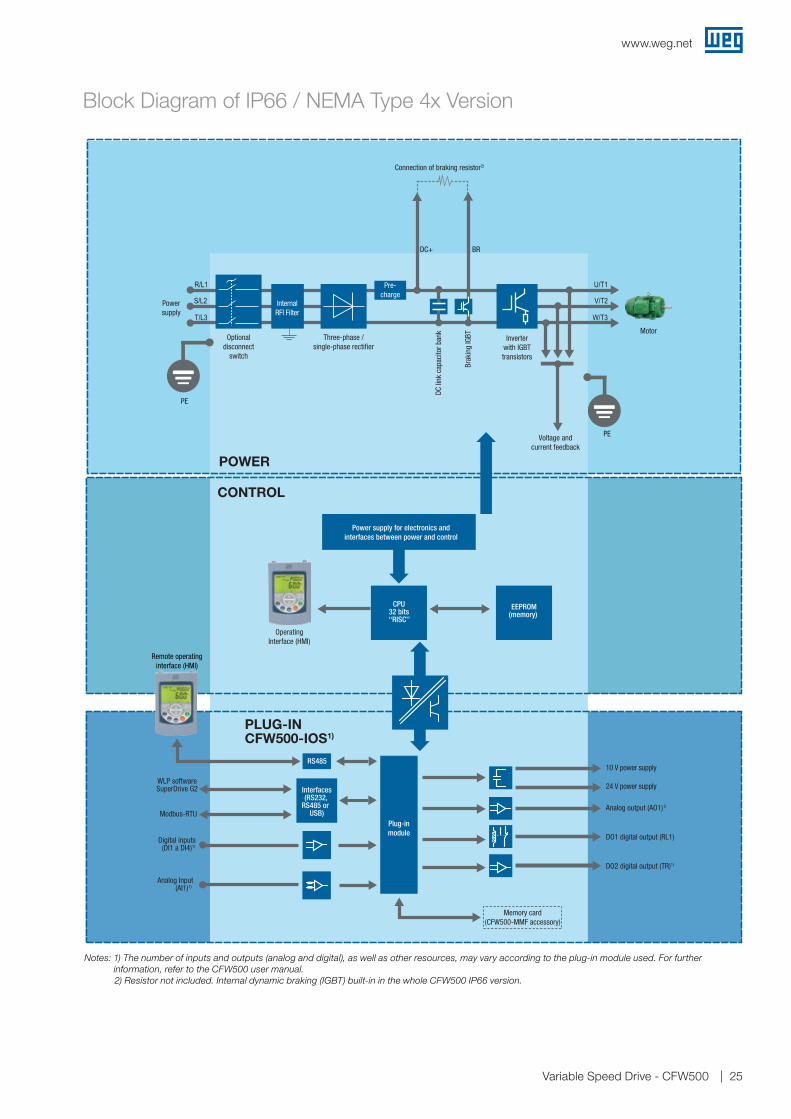
Block Diagram of IP66 / NEMA Type 4x Version
Notes: 1) The number of inputs and outputs (analog and digital), as well as other resources, may vary according to the plug-in module used. For further information, refer to the CFW500 user manual.
2) Resistor not included. Internal dynamic braking (IGBT) built-in in the whole CFW500 IP66 version.
PE
PE
DC+ BR
Power supply for electronics andinterfaces between power and control
CONTROL
Remote operatinginterface (HMI)
CPU32 bits‘‘RISC’’
EEPROM(memory)
Plug-inmodule
24 V power supply
Analog output (AO1)1)
DO2 digital output (TR)1)
DO1 digital output (RL1)
Memory card(CFW500-MMF accessory)
RS48510 V power supply
Interfaces(RS232,
RS485 or USB)
WLP softwareSuperDrive G2
Modbus-RTU
Digital inputs(DI1 a DI4)1)
Analog Input(AI1)1)
CFW500-IOS1)
POWER
Connection of braking resistor2)
Inverterwith IGBTtransistors
Powersupply
R/L1
S/L2
T/L3
U/T1
V/T2
W/T3Motor
Voltage andcurrent feedback
Three-phase /single-phase rectifier
Optionaldisconnect
switch
OperatingInterface (HMI)
DC li
nk c
apac
itor b
ank
Brak
ing
IGBT
InternalRFI Filter
Pre-charge
PLUG-IN

www.weg.net
Variable Speed Drive - CFW50026
Partnership is to create solutions that suit your needs
Competitive edge is to unite technology and innovation
Availability is to have a global support network
Global presence is essential, as much as understanding your needs.
Global PresenceWith more than 30.000 employees worldwide, WEG is one of the largest electric motors, electronic equipments and systems manufacturers. We are constantly expanding our portfolio of products and services with expertise and market knowledge. We create integrated and customized solutions ranging from innovative products to complete after-sales service.
WEG’s know-how guarantees our CFW500 are the right choice for your application and business, assuring safety, efficiency and reliability.

www.weg.net
Variable Speed Drive - CFW500 27
Visit: www.weg.net youtube.com/wegvideos
High performance and reliable products to improve your production process.
Know More
Excelence is to provide a whole solution in industrial automation that improves our customers productivity.

www.weg.net
The values shown are subject to change without prior notice. The information contained is reference values.
Cod: 50036259 | Rev: 13 | Date (m/a): 06/2020.
AUTOMATIONJaraguá do Sul - SC - Brazil
+55 47 3276.4000
For WEG’s worldwide operations visit our website