cfw701 programming
DESCRIPTION
CFW701 ProgrammingTRANSCRIPT
Motors | Automation | Energy | Transmission & Distribution | Coatings
Frequency Inverter
CFW701
Programming and Troubleshooting Manual


Programming and Troubleshooting Manual
Series: CFW701
Language: English
Document Number: 10001461481 / 00
Software Version: 1.2X
Publication Date: 04/2012


Summary
QUICK PARAMETER REFERENCE, FAULTS AND ALARMS ................. 0-1
1 SAFETY NOTICES ................................................................................. 1-11.1 SAFETY NOTICES IN THIS MANUAL ............................................................................................1-11.2 SAFETY NOTICES ON THE PRODUCT .........................................................................................1-11.3 PRELIMINARY RECOMMENDATIONS ..........................................................................................1-2
2 GENERAL INFORMATION ...................................................................... 2-12.1 ABOUT THIS MANUAL ...................................................................................................................2-12.2 TERMINOLOGY AND DEFINITIONS..............................................................................................2-1
2.2.1 Terms and Definitions Used in the Manual ........................................................................2-12.2.2 Numerical Representation ................................................................................................. 2-32.2.3 Symbols for the Parameter Properties Description ........................................................ 2-3
3 ABOUT THE CFW701 ............................................................................. 3-1
4 KEYPAD (HMI) ......................................................................................... 4-1
5 PROGRAMMING BASIC INSTRUCTIONS ............................................. 5-15.1 PARAMETERS STRUCTURE ......................................................................................................... 5-15.2 GROUPS ACCESSED IN THE OPTION MENU IN THE MONITORING MODE .......................... 5-15.3 PASSWORD SETTING IN P0000 ................................................................................................... 5-25.4 HMI .................................................................................................................................................. 5-35.5 INDIRECT ENGINEERING UNITS ................................................................................................. 5-65.6 DISPLAY INDICATIONS IN THE MONITORING MODE SETTINGS .........................................5-135.7 INCOMPATIBILITY BETWEEN PARAMETERS ..........................................................................5-14
6 INVERTER MODEL AND ACCESSORIES IDENTIFICATION ............... 6-16.1 INVERTER DATA ........................................................................................................................... 6-1
7 STARTING-UP AND SETTINGS ............................................................. 7-17.1 BACKUP PARAMETERS .................................................................................................................7-1
8 AVAILABLE CONTROL TYPES .............................................................. 8-1
9 SCALAR CONTROL (V/f) ........................................................................ 9-19.1 V/F CONTROL ................................................................................................................................. 9-29.2 ADJUSTABLE V/F CURVE ............................................................................................................. 9-59.3 V/F CURRENT LIMITATION .......................................................................................................... 9-79.4 V/F DC VOLTAGE LIMITATION ...................................................................................................... 9-99.5 START-UP IN THE V/F CONTROL MODE ...................................................................................9-12
10 VVW CONTROL .................................................................................. 10-110.1 VVW CONTROL ......................................................................................................................... 10-310.2 MOTOR DATA ............................................................................................................................ 10-310.3 VVW CONTROL MODE START-UP ......................................................................................... 10-5
Summary
11 VECTOR CONTROL .............................................................................11-111.1 SENSORLESS CONTROL ..........................................................................................................11-111.2 I/f MODE (SENSORLESS) ..........................................................................................................11-311.3 SELF-TUNING .............................................................................................................................11-311.4 OPTIMAL FLUX FOR SENSORLESS VECTOR CONTROL ....................................................11-411.5 TORQUE CONTROL ....................................................................................................................11-511.6 OPTIMAL BRAKING ...................................................................................................................11-611.7 MOTOR DATA ..............................................................................................................................11-8
11.7.1 Adjustment of the Parameters P0409 to P0412 Based on the Motor Data Sheet .... 11-1211.8 VECTOR CONTROL ................................................................................................................. 11-12
11.8.1 Speed Regulator ............................................................................................................. 11-1211.8.2 Current Regulator .......................................................................................................... 11-1511.8.3 Flux Regulator ................................................................................................................ 11-1511.8.4 I/f Control ....................................................................................................................... 11-1711.8.5 Self-Tuning ....................................................................................................................... 11-1811.8.6 Torque Current Limitation ..............................................................................................11-2211.8.7 DC Link Regulator ...........................................................................................................11-23
11.9 START-UP IN THE VECTOR MODES SENSORLESS .............................................................11-25
12 FUNCTIONS COMMON TO ALL THE CONTROL MODES ............... 12-112.1 RAMPS .........................................................................................................................................12-112.2 SPEED REFERENCES .............................................................................................................. 12-312.3 SPEED LIMITS ........................................................................................................................... 12-512.4 ZERO SPEED LOGIC ..................................................................................................................12-712.5 FLYING START / RIDE-THROUGH ............................................................................................ 12-8
12.5.1 V/f or VVW Flying Start ................................................................................................... 12-912.5.2 Vector Flying Start ........................................................................................................... 12-9
12.5.2.1 P0202=4 ................................................................................................................. 12-912.5.3 VVW or V/f Ride-Through ..............................................................................................12-1212.5.4 Vector Ride-Through ......................................................................................................12-13
12.6 DC BRAKING .............................................................................................................................12-1712.7 SKIP SPEED .............................................................................................................................12-21
13 DIGITAL AND ANALOG INPUTS AND OUTPUTS ............................. 13-113.1 I/O CONFIGURATION .................................................................................................................13-1
13.1.1 Analog Inputs ....................................................................................................................13-113.1.2 Analog Outputs ................................................................................................................. 13-613.1.3 Digital Inputs ..................................................................................................................... 13-913.1.4 Digital Outputs / Relays ..................................................................................................13-16
13.2 LOCAL AND REMOTE COMMAND ........................................................................................ 13-25
14 DYNAMIC BRAKING ........................................................................... 14-1
15 FAULTS AND ALARMS ....................................................................... 15-115.1 MOTOR OVERLOAD PROTECTION ...........................................................................................15-115.2 MOTOR OVERTEMPERATURE PROTECTION ........................................................................ 15-215.3 PROTECTIONS ........................................................................................................................... 15-4
Summary
16 READ ONLY PARAMETERS ............................................................... 16-116.1 FAULT HISTORY ..........................................................................................................................16-7
17 COMMUNICATION ..............................................................................17-117.1 RS-485 SERIAL INTERFACE ...................................................................................................... 17-117.2 COMMUNICATION BACNET ...................................................................................................... 17-117.3 COMMUNICATION METASYS N2 ..............................................................................................17-217.4 COMMUNICATION STATES AND COMMANDS .......................................................................17-2
18 SOFTPLC [50] ...................................................................................... 18-1
19 HVAC FUNCTIONS .............................................................................. 19-119.1 FIRE MODE ..................................................................................................................................19-119.2 BYPASS MODE .......................................................................................................................... 19-319.3 ENERGY SAVING MODE ........................................................................................................... 19-619.4 SHORT CYCLE PROTECTION ................................................................................................... 19-819.5 DRY PUMP .................................................................................................................................. 19-919.6 BROKEN BELT ..........................................................................................................................19-1119.7 FILTER MAINTENANCE ALARM ..............................................................................................19-1219.8 MAIN PID CONTROLLER .........................................................................................................19-13
19.8.1 Sleep Mode ..................................................................................................................... 19-2219.9 EXTERNAL PID CONTROLLER 1 ........................................................................................... 19-2519.10 EXTERNAL PID CONTROLLER 2 .......................................................................................... 19-3219.11 HVAC FUNCTIONS LOGICAL STATUS ................................................................................. 19-40
20 MAINTENANCE ...................................................................................20-120.1 PREVENTIVE MAINTENANCE .................................................................................................. 20-120.2 CLEANING INSTRUCTIONS ..................................................................................................... 20-2

Summary

0
Quick Parameter Reference, Faults and Alarms
CFW701 | 0-1
QUICK PARAMETER REFERENCE, FAULTS AND ALARMS
Param. Function Adjustable Range Factory SettingUser
SettingPropr. Groups Pág.
P0000 Access to Parameters 0 to 9999 0 5-2P0001 Speed Reference 0 to 18000 rpm ro 16-1P0002 Motor Speed 0 to 18000 rpm ro 16-1P0003 Motor Current 0.0 to 4500.0 A ro 16-1P0004 DC Link Voltage (Ud) 0 to 2000 V ro 16-2P0005 Motor Frequency 0.0 to 1020.0 Hz ro 16-2P0006 VFD Status 0 = Ready
1 = Run2 = Undervoltage3 = Fault4 = Self-Tuning5 = Configuration6 = DC-Braking7 = STO8 = Fire Mode9 = Bypass
ro 16-2
P0007 Motor Voltage 0 to 2000 V ro 16-3P0009 Motor Torque -1000.0 to 1000.0 % ro 16-3P0010 Output Power 0.0 to 6553.5 kW ro 16-4P0011 Output cos φ 0.00 to 1.00 ro I/O 16-4P0012 DI8 to DI1 Status Bit 0 = DI1
Bit 1 = DI2Bit 2 = DI3Bit 3 = DI4Bit 4 = DI5Bit 5 = DI6Bit 6 = DI7Bit 7 = DI8
ro I/O 13-10 16-4
P0013 DO5 to DO1 Status Bit 0 = DO1Bit 1 = DO2Bit 2 = DO3Bit 3 = DO4Bit 4 = DO5
ro I/O 13-16 16-5
P0014 AO1 Value 0.00 to 100.00 % ro I/O 13-6 16-5
P0015 AO2 Value 0.00 to 100.00 % ro I/O 13-6 16-5
P0018 AI1 Value -100.00 to 100.00 % ro I/O 13-1 16-5
P0019 AI2 Value -100.00 to 100.00 % ro I/O 13-1 16-5
P0020 AI3 Value -100.00 to 100.00 % ro I/O 13-1 16-5
P0023 Software Version 0.00 to 655.35 ro 6-1 16-5
P0028 Accessories Config. 0000h to FFFFh ro 6-2 16-5
P0029 Power Hardware Config Bit 0....5 = Rated CurrentBit 6 and 7 = Rated VoltageBit 8 = EMC FilterBit 9 = Safety RelayBit 10 = (0)24 V/(1)DC LinkBit 11 = Always 0Bit 12 = Dyn.Brak. IGBTBit 13 = SpecialBit 14 and 15 = Reserved
ro 6-2 16-5
P0030 IGBTs Temperature -20.0 to 150.0 °C ro 15-4 16-5
P0034 Internal Air Temp. -20.0 to 150.0 °C ro 15-4 16-5
P0036 Fan Heatsink Speed 0 to 15000 rpm ro 16-5P0037 Motor Overload Status 0 to 100 % ro 16-5P0042 Time Powered 0 to 65535 h ro 16-6P0043 Time Enabled 0.0 to 6553.5 h ro 16-6

0
Quick Parameter Reference, Faults and Alarms
0-2 | CFW701
Param. Function Adjustable Range Factory SettingUser
SettingPropr. Groups Pág.
P0044 kWh Output Energy 0 to 65535 kWh ro 16-6P0045 Fan Enabled Time 0 to 65535 h ro 16-7P0048 Present Alarm 0 to 999 ro 16-7P0049 Present Fault 0 to 999 ro 16-7P0050 Last Fault 0 to 999 ro 16-7P0054 Second Fault 0 to 999 ro 16-7P0058 Third Fault 0 to 999 ro 16-7P0062 Fourth Fault 0 to 999 ro 16-7P0066 Fifth Fault 0 to 999 ro 16-8P0090 Current At Last Fault 0.0 to 4500.0 A ro 16-8P0091 DC Link At Last Fault 0 to 2000 V ro 16-8P0092 Speed At Last Fault 0 to 18000 rpm ro 16-8P0093 Reference Last Fault 0 to 18000 rpm ro 16-9P0094 Frequency Last Fault 0.0 to 1020.0 Hz ro 16-9P0095 Motor Volt.Last Fault 0 to 2000 V ro 16-9P0096 DIx Status Last Fault Bit 0 = DI1
Bit 1 = DI2Bit 2 = DI3Bit 3 = DI4Bit 4 = DI5Bit 5 = DI6Bit 6 = DI7Bit 7 = DI8
ro 16-9
P0097 DOx Status Last Fault Bit 0 = DO1Bit 1 = DO2Bit 2 = DO3Bit 3 = DO4Bit 4 = DO5
ro 16-10
P0100 Acceleration Time 0.0 to 999.0 s 20.0 s BASIC 12-1P0101 Deceleration Time 0.0 to 999.0 s 20.0 s BASIC 12-1P0102 Acceleration Time 2 0.0 to 999.0 s 20.0 s 12-1P0103 Deceleration Time 2 0.0 to 999.0 s 20.0 s 12-1P0104 Ramp Type 0 = Linear
1 = S Ramp0 = Linear 12-2
P0105 1st/2nd Ramp Select. 0 = 1st Ramp1 = 2nd Ramp2 = DIx3 = Serial4 = SoftPLC
2 = DIx cfg 12-3
P0120 Speed Ref. Backup 0 = Off1 = On
1 = On 12-3
P0121 Keypad Reference 0 to 18000 rpm 90 rpm 12-4P0122 JOG/JOG + Reference 0 to 18000 rpm 150 (125) rpm 12-4
12-5P0123 JOG - Reference 0 to 18000 rpm 150 (125) rpm Vector 12-5P0132 Max. Overspeed Level 0 to 100 % 10 % cfg 12-5P0133 Minimum Speed 0 to 18000 rpm 90 (75) rpm BASIC 12-6P0134 Maximum Speed 0 to 18000 rpm 1800 (1500) rpm BASIC 12-6P0135 Max. Output Current 0.2 to 2xInom-HD 1.5xInom-HD V/F VVW BASIC 9-7P0136 Manual Torque Boost 0 to 9 1 V/F BASIC 9-2P0137 Autom. Torque Boost 0.00 to 1.00 0.00 V/F 9-2P0138 Slip Compensation -10.0 to 10.0 % 0.0 % V/F 9-3P0139 Output Current Filter 0.0 to 16.0 s 0.2 s V/F VVW 9-4P0142 Max. Output Voltage 0.0 to 100.0 % 100.0 % cfg Adj 9-5P0143 Interm.Output Voltage 0.0 to 100.0 % 50.0 % cfg Adj 9-5P0144 3Hz Output Voltage 0.0 to 100.0 % 8.0 % cfg Adj 9-5P0145 Field Weakening Speed 0 to 18000 rpm 1800 rpm cfg Adj 9-6P0146 Intermediate Speed 0 to 18000 rpm 900 rpm cfg Adj 9-6P0150 DC Regul. Type V/f 0 = Ramp Hold
1 = Ramp Accel.0 = Ramp Hold cfg V/F
VVW9-11
P0151 DC Regul. Level V/f 339 to 1000 V 800 V V/F VVW 9-11
0
Quick Parameter Reference, Faults and Alarms
CFW701 | 0-3
Param. Function Adjustable Range Factory SettingUser
SettingPropr. Groups Pág.
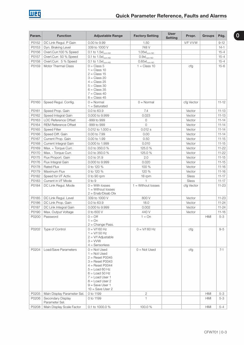
P0152 DC Link Regul. P Gain 0.00 to 9.99 1.50 V/F VVW 9-12P0153 Dyn. Braking Level 339 to 1000 V 748 V 14-1P0156 Overl.Curr.100 % Speed 0.1 to 1.5xInom-ND 1.05xInom-ND 15-4P0157 Overl.Curr. 50 % Speed 0.1 to 1.5xInom-ND 0.9xInom-ND 15-4P0158 Overl.Curr. 5 % Speed 0.1 to 1.5xInom-ND 0.65xInom-ND 15-4P0159 Motor Thermal Class 0 = Class 5
1 = Class 102 = Class 153 = Class 204 = Class 255 = Class 306 = Class 357 = Class 408 = Class 45
1 = Class 10 cfg 15-6
P0160 Speed Regul. Config. 0 = Normal1 = Saturated
0 = Normal cfg Vector 11-12
P0161 Speed Prop. Gain 0.0 to 63.9 7.4 Vector 11-13P0162 Speed Integral Gain 0.000 to 9.999 0.023 Vector 11-13P0163 LOC Reference Offset -999 to 999 0 Vector 11-14P0164 REM Reference Offset -999 to 999 0 Vector 11-14P0165 Speed Filter 0.012 to 1.000 s 0.012 s Vector 11-14P0166 Speed Diff. Gain 0.00 to 7.99 0.00 Vector 11-14P0167 Current Prop. Gain 0.00 to 1.99 0.50 Vector 11-15P0168 Current Integral Gain 0.000 to 1.999 0.010 Vector 11-15P0169 Max. + Torque Curr. 0.0 to 350.0 % 125.0 % Vector 11-22P0170 Max. - Torque Curr. 0.0 to 350.0 % 125.0 % Vector 11-22P0175 Flux Proport. Gain 0.0 to 31.9 2.0 Vector 11-15P0176 Flux Integral Gain 0.000 to 9.999 0.020 Vector 11-15P0178 Rated Flux 0 to 120 % 100 % Vector 11-16P0179 Maximum Flux 0 to 120 % 120 % Vector 11-16P0182 Speed for I/F Activ. 0 to 90 rpm 18 rpm Sless 11-17P0183 Current in I/F Mode 0 to 9 1 Sless 11-17P0184 DC Link Regul. Mode 0 = With losses
1 = Without losses2 = Enab/Disab DIx
1 = Without losses cfg Vector 11-23
P0185 DC Link Regul. Level 339 to 1000 V 800 V Vector 11-23P0186 DC Link Prop. Gain 0.0 to 63.9 18.0 Vector 11-24P0187 DC Link Integral Gain 0.000 to 9.999 0.002 Vector 11-24P0190 Max. Output Voltage 0 to 600 V 440 V Vector 11-16P0200 Password 0 = Off
1 = On2 = Change Pass.
1 = On HMI 5-3
P0202 Type of Control 0 = V/f 60 Hz1 = V/f 50 Hz2 = V/f Adjustable3 = VVW4 = Sensorless
0 = V/f 60 Hz cfg 9-5
P0204 Load/Save Parameters 0 = Not Used1 = Not Used2 = Reset P00453 = Reset P00434 = Reset P00445 = Load 60 Hz6 = Load 50 Hz7 = Load User 18 = Load User 29 = Save User 110 = Save User 2
0 = Not Used cfg 7-1
P0205 Main Display Parameter Sel. 0 to 1199 2 HMI 5-3P0206 Secondary Display
Parameter Sel.0 to 1199 1 HMI 5-3
P0208 Main Display Scale Factor 0.1 to 1000.0 % 100.0 % HMI 5-4
0
Quick Parameter Reference, Faults and Alarms
0-4 | CFW701
Param. Function Adjustable Range Factory SettingUser
SettingPropr. Groups Pág.
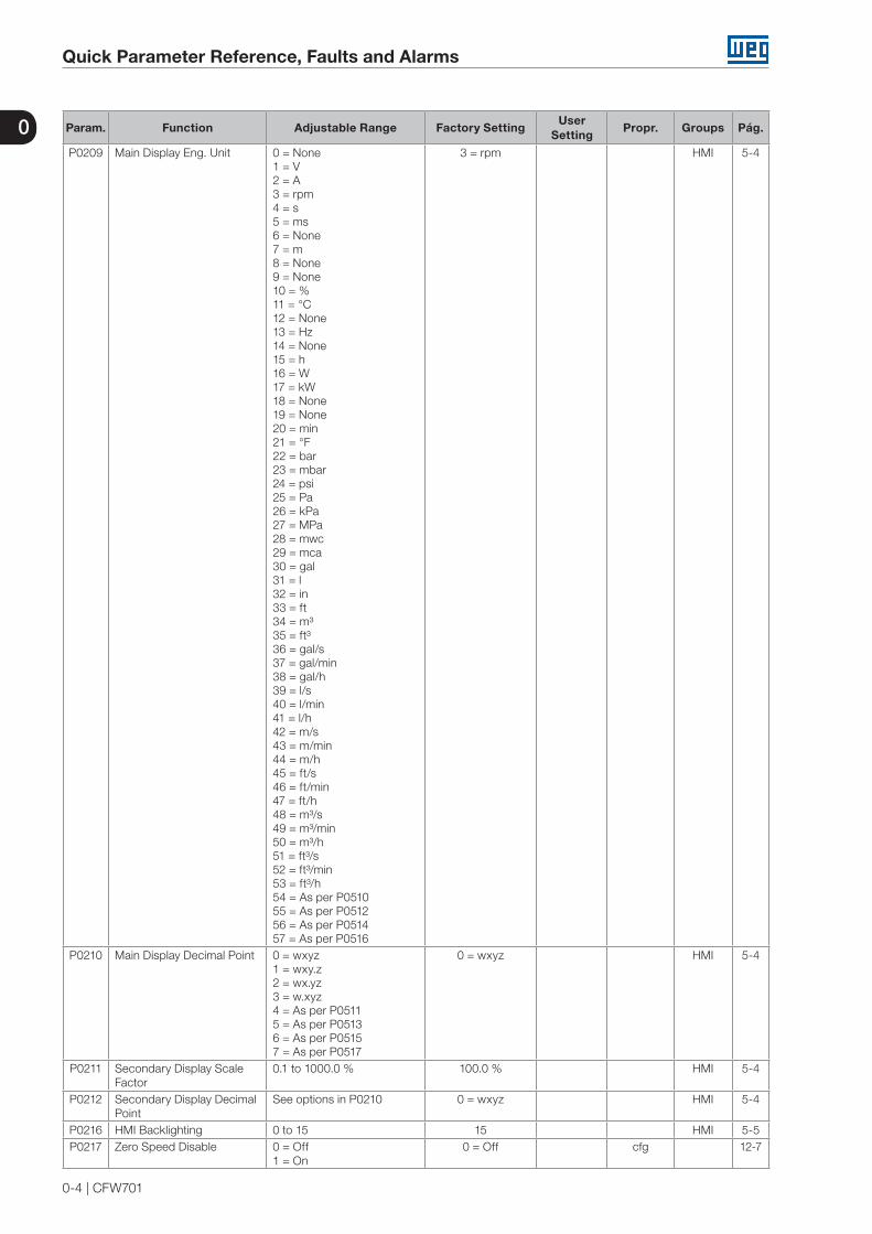
P0209 Main Display Eng. Unit 0 = None1 = V2 = A3 = rpm4 = s5 = ms6 = None7 = m8 = None9 = None10 = %11 = °C12 = None13 = Hz14 = None15 = h16 = W17 = kW18 = None19 = None20 = min21 = °F22 = bar23 = mbar24 = psi25 = Pa26 = kPa27 = MPa28 = mwc29 = mca30 = gal31 = l32 = in33 = ft34 = m³35 = ft³36 = gal/s37 = gal/min38 = gal/h39 = l/s40 = l/min41 = l/h42 = m/s43 = m/min44 = m/h45 = ft/s46 = ft/min47 = ft/h48 = m³/s49 = m³/min50 = m³/h51 = ft³/s52 = ft³/min53 = ft³/h54 = As per P051055 = As per P051256 = As per P051457 = As per P0516
3 = rpm HMI 5-4
P0210 Main Display Decimal Point 0 = wxyz1 = wxy.z2 = wx.yz3 = w.xyz4 = As per P05115 = As per P05136 = As per P05157 = As per P0517
0 = wxyz HMI 5-4
P0211 Secondary Display Scale Factor
0.1 to 1000.0 % 100.0 % HMI 5-4
P0212 Secondary Display Decimal Point
See options in P0210 0 = wxyz HMI 5-4
P0216 HMI Backlighting 0 to 15 15 HMI 5-5P0217 Zero Speed Disable 0 = Off
1 = On0 = Off cfg 12-7

0
Quick Parameter Reference, Faults and Alarms
CFW701 | 0-5
Param. Function Adjustable Range Factory SettingUser
SettingPropr. Groups Pág.
P0218 Zero Speed Dis. Out 0 = Ref. or Speed1 = Reference
0 = Ref. or Speed 12-7
P0219 Zero Speed Time 0 to 999 s 0 s 12-8P0220 LOC/REM Selection Src 0 = Always LOC
1 = Always REM2 = LR Key LOC3 = LR Key REM4 = DIx5 = Serial LOC6 = Serial REM7 = SoftPLC LOC8 = SoftPLC REM
2 = LR Key LOC cfg IO 13-25
P0221 LOC Reference Sel. 0 = Keypad1 = AI12 = AI23 = AI34 = Sum AIs > 05 = Sum AIs6 = Serial7 = SoftPLC
0 = Keypad cfg IO 13-25
P0222 REM Reference Sel. See options in P0221 1 = AI1 cfg IO 13-25P0223 LOC FWD/REV Selection 0 = Always FWD
1 = Always REV2 = FR Key FWD3 = FR Key REV4 = DIx5 = Serial FWD6 = Serial REV7 = SoftPLC FWD8 = SoftPLC REV9 = AI2 Polarity
2 = FR Key FWD cfg IO 13-26
P0224 LOC Run/Stop Sel. 0 = I,O Keys1 = DIx2 = Serial3 = SoftPLC
0 = I,O Keys cfg IO 13-26
P0225 LOC JOG Selection 0 = Disable1 = JOG Key2 = DIx3 = Serial4 = SoftPLC
1 = JOG Key cfg IO 13-27
P0226 REM FWD/REV Sel. See options in P0223 4 = DIx cfg IO 13-26P0227 REM Run/Stop Sel. See options in P0224 1 = DIx cfg IO 13-26P0228 REM JOG Selection See options in P0225 2 = DIx cfg IO 13-27P0229 Stop Mode Selection 0 = Ramp to Stop
1 = Coast to Stop2 = Fast Stop
0 = Ramp to Stop cfg 13-27
P0230 Dead Zone (AIs) 0 = Off1 = On
0 = Off IO 13-1
P0231 AI1 Signal Function 0 = Speed Ref.1 = No Ramp Ref.2 = Max.Torque Cur3 = SoftPLC4 = PTC5 = Main PID Feedback 16 = Main PID Feedback 27 = Main PID Feedback 38 = External PID 1 Feedback9 = External PID 2 Feedback
5 = Main PID Feedback 1
cfg IO 13-2
P0232 AI1 Gain 0.000 to 9.999 1.000 IO 13-4P0233 AI1 Signal Type 0 = 0 to 10 V/20 mA
1 = 4 to 20 mA2 = 10 V/20 mA to 03 = 20 to 4 mA4 = -10 to +10 V
0 = 0 to 10 V/20 mA cfg IO 13-5
P0234 AI1 Offset -100.00 to 100.00 % 0.00 % IO 13-4P0235 AI1 Filter 0.00 to 16.00 s 0.00 s IO 13-4P0236 AI2 Signal Function See options in P0231 8 = External PID 1
Feedbackcfg IO 13-2
P0237 AI2 Gain 0.000 to 9.999 1.000 IO 13-4

0
Quick Parameter Reference, Faults and Alarms
0-6 | CFW701
Param. Function Adjustable Range Factory SettingUser
SettingPropr. Groups Pág.
P0238 AI2 Signal Type See parameter in P0233 0 = 0 to 10 V/20 mA cfg IO 13-5P0239 AI2 Offset -100.00 to 100.00 % 0.00 % IO 13-4P0240 AI2 Filter 0.00 to 16.00 s 0.00 s IO 13-4P0241 AI3 Signal Function 0 = Speed Ref.
1 = No Ramp Ref.2 = Max.Torque Cur3 = SoftPLC4 = Reserved5 = Main PID Feedback 16 = Main PID Feedback 27 = Main PID Feedback 38 = External PID 1 Feedback9 = External PID 2 Feedback
9 = External PID 2 Feedback
cfg IO 13-2
P0242 AI3 Gain 0.000 to 9.999 1.000 IO 13-4P0243 AI3 Signal Type 0 = 0 to 20mA
1 = 4 to 20 mA2 = 20 to 0 mA3 = 20 to 4 mA
0 = 0 to 20mA cfg IO 13-6
P0244 AI3 Offset -100.00 to 100.00 % 0.00 % IO 13-4P0245 AI3 Filter 0.00 to 16.00 s 0.00 s IO 13-4P0251 AO1 Function 0 = Speed Ref.
1 = Total Ref.2 = Real Speed3 = Torque Cur.Ref4 = Torque Current5 = Output Current6 = Active Current7 = Output Power8 = Torque Cur.> 09 = Motor Torque10 = SoftPLC11 = PTC12 = Motor Ixt13 = P0696 Value14 = P0697 Value15 = Id* Current16 = External PID 1 Output17 = External PID 2 Output
16 = External PID 1 Output
IO 13-7
P0252 AO1 Gain 0.000 to 9.999 1.000 IO 13-7P0253 AO1 Signal Type 0 = 0 to 10 V/20 mA
1 = 4 to 20 mA2 = 10 V/20 mA to 03 = 20 to 4 mA
0 = 0 to 10 V/20 mA cfg IO 13-9
P0254 AO2 Function See options in P0251 17 = External PID 2 Output
IO 13-7
P0255 AO2 Gain 0.000 to 9.999 1.000 IO 13-7P0256 AO2 Signal Type See options in P0256 0 = 0 to 10 V/20 mA cfg IO 13-9P0263 DI1 Function 0 = Not Used
1 = Run/Stop2 = General Enable3 = Fast Stop4 = FWD/REV5 = LOC/REM6 = JOG7 = SoftPLC8 = Ramp 29 = Speed/Torque10 = JOG+11 = JOG-12 = No Ext. Alarm13 = No Ext. Fault14 = Reset15 = Disab.FlyStart16 = DC Link Regul.17 = Progr. Off18 = Load User 119 = Load User 220 = Main PID Aut/Man21 = External PID 1 Aut/Man22 = External PID 2 Aut/Man23 = Bypass Mode24 = Fire Mode
1 = Run/Stop cfg IO 13-10

0
Quick Parameter Reference, Faults and Alarms
CFW701 | 0-7
Param. Function Adjustable Range Factory SettingUser
SettingPropr. Groups Pág.
P0264 DI2 Function See options in P0263 4 = FWD/REV cfg IO 13-10P0265 DI3 Function See options in P0263 0 = Not Used cfg IO 13-10P0266 DI4 Function See options in P0263 20 = Main PID Aut/
Mancfg IO 13-10
P0267 DI5 Function See options in P0263 21 = External PID 1 Aut/Man
cfg IO 13-10
P0268 DI6 Function See options in P0263 22 = External PID 2 Aut/Man
cfg IO 13-10
P0269 DI7 Function See options in P0263 0 = Not Used cfg IO 13-10P0270 DI8 Function See options in P0263 0 = Not Used cfg IO 13-11P0275 DO1 Function (RL1) 0 = Not Used
1 = N* > Nx2 = N > Nx3 = N < Ny4 = N = N*5 = Zero Speed6 = Is > Ix7 = Is < Ix8 = Torque > Tx9 = Torque < Tx10 = Remote11 = Run12 = Ready13 = No Fault14 = No F07015 = No F07116 = No F006/21/2217 = No F05118 = No F07219 = 4-20 mA OK20 = P0695 Value21 = Forward22 = Ride-Through23 = Pre-Charge OK24 = Fault25 = Time Enab > Hx26 = SoftPLC27 = N>Nx/Nt>Nx28 = F > Fx (1)29 = F > Fx (2)30 = STO31 = No F16032 = No Alarm33 = No Fault/Alarm34 = Dry Pump Alarm/Fault35 = Broken Belt Alarm/Fault36 = Filter Mainten.Alarm/Fault37 = Sleep Mode38 = Not Used39 = Drive Bypass Contactor40 = Mains Bypass Contactor41 = Fire Mode42 = Self-Tuning
13 = No Fault cfg IO 13-16
P0276 DO2 Function (RL2) See options in P0275 2 = N > Nx cfg IO 13-16P0277 DO3 Function See options in P0275 1 = N* > Nx cfg IO 13-16P0278 DO4 Function See options in P0275 0 = Not Used cfg IO 13-16P0279 DO5 Function See options in P0275 0 = Not Used cfg IO 13-17P0281 Fx Frequency 0.0 to 300.0 Hz 4.0 Hz 13-22P0282 Fx Hysteresis 0.0 to 15.0 Hz 2.0 Hz 13-22P0287 Nx/Ny Hysteresis 0 to 900 rpm 18 (15) rpm 13-23P0288 Nx Speed 0 to 18000 rpm 120 (100) rpm 13-23P0289 Ny Speed 0 to 18000 rpm 1800 (1500) rpm 13-23P0290 Ix Current 0 to 2xInom-ND 1.0xInom-ND 13-23P0291 Zero Speed Zone 0 to 18000 rpm 18 (15) rpm 12-8
13-24P0292 N = N* Band 0 to 18000 rpm 18 (15) rpm 13-24P0293 Tx Torque 0 to 200 % 100 % 13-24

0
Quick Parameter Reference, Faults and Alarms
0-8 | CFW701
Param. Function Adjustable Range Factory SettingUser
SettingPropr. Groups Pág.
P0294 Hx Time 0 to 6553 h 4320 h 13-24P0295 ND/HD VFD Rated Curr. 0 = 2 A / 2 A
1 = 3.6 A / 3.6 A2 = 5 A / 5 A3 = 6 A / 5 A4 = 7 A / 5.5 A5 = 7 A / 7 A6 = 10 A / 8 A7 = 10 A / 10 A8 = 13 A / 11 A9 = 13.5 A / 11 A10 = 16 A / 13 A11 = 17 A / 13.5 A12 = 24 A / 19 A13 = 24 A / 20 A14 = 28 A / 24 A15 = 31 A / 25 A16 = 33.5 A / 28 A17 = 38 A / 33 A18 = 45 A / 36 A19 = 45 A / 38 A20 = 54 A / 45 A21 = 58.5 A / 47 A22 = 70 A / 56 A23 = 70.5 A / 61 A24 = 86 A / 70 A25 = 88 A / 73 A26 = 105 A / 86 A27 = 105 A / 88 A28 = 142 A / 115 A29 = 180 A / 142 A30 = 211 A / 180 A31 = 2.9 A / 2.7 A32 = 4.2 A / 3.8 A33 = 7 A / 6.5 A34 = 10 A / 9 A35 = 12 A / 10 A36 = 17 A / 17 A37 = 22 A / 19 A38 = 27 A / 22 A39 = 32 A / 27 A40 = 44 A / 36 A41 = 53 A / 44 A42 = 63 A / 53 A43 = 80 A / 66 A44 = 107 A / 90 A45 = 125 A / 107 A46 = 150 A / 122 A
ro 6-5
P0296 Line Rated Voltage 0 = 200 - 240 V1 = 380 V2 = 400 - 415 V3 = 440 - 460 V4 = 480 V5 = 500 - 525 V6 = 550 - 575 V7 = 600 V
According to inverter model
cfg 6-6
P0297 Switching Frequency 0 = 1.25 kHz1 = 2.5 kHz2 = 5.0 kHz3 = 10.0 kHz4 = 2.0 kHz
2 = 5.0 kHz cfg 6-7
P0298 Application 0 = Normal Duty1 = Heavy Duty
0 = Normal Duty cfg 6-7
P0299 DC-Braking Start Time 0.0 to 15.0 s 0.0 s V/F VVW Sless
12-17
P0300 DC-Braking Stop Time 0.0 to 15.0 s 0.0 s V/F VVW Sless
12-18
P0301 DC-Braking Speed 0 to 450 rpm 30 rpm V/F VVW Sless
12-19
P0302 DC-Braking Voltage 0.0 to 10.0 % 2.0 % V/F VVW 12-20

0
Quick Parameter Reference, Faults and Alarms
CFW701 | 0-9
Param. Function Adjustable Range Factory SettingUser
SettingPropr. Groups Pág.
P0303 Skip Speed 1 0 to 18000 rpm 600 rpm 12-21P0304 Skip Speed 2 0 to 18000 rpm 900 rpm 12-21P0305 Skip Speed 3 0 to 18000 rpm 1200 rpm 12-21P0306 Skip Band 0 to 750 rpm 0 rpm 12-21P0308 Serial Address 1 to 247 1 NET 17-1P0310 Serial Baud Rate 0 = 9600 bits/s
1 = 19200 bits/s2 = 38400 bits/s3 = 57600 bits/s
1 = 19200 bits/s NET 17-1
P0311 Serial Bytes Config. 0 = 8 bits, no, 11 = 8 bits, even,12 = 8 bits, odd, 13 = 8 bits, no, 24 = 8 bits, even,25 = 8 bits, odd, 2
1 = 8 bits, even,1 NET 17-1
P0312 Serial Protocol 2 = Modbus RTU3 = BACnet4 = N2
2 = Modbus RTU NET 17-1
P0313 Comm. Error Action 0 = Off1 = Ramp Stop2 = General Disab.3 = Go to LOC4 = LOC Keep Enab.5 = Cause Fault
0 = Off NET 17-2
P0314 Serial Watchdog 0.0 to 999.0 s 0.0 s NET 17-1P0316 Serial Interf. Status 0 = Off
1 = On2 = Watchdog Error
ro NET 17-1
P0317 Oriented Start-up 0 = No1 = Yes
0 = No cfg 7-2
P0318 Copy Function MMF 0 = Off1 = VFD -> MMF2 = MMF -> VFD3 = Sync VFD -> MMF4 = Format MMF5 = Copy SoftPLC Prog.
0 = Off cfg 7-3
P0320 FlyStart/Ride-Through 0 = Off1 = Flying Start2 = FS / RT3 = Ride-Through
0 = Off cfg 12-8
P0321 DC Link Power Loss 178 to 770 V 505 V Vector 12-15P0322 DC Link Ride-Through 178 to 770 V 490 V Vector 12-15P0323 DC Link Power Back 178 to 770 V 534 V Vector 12-15P0325 Ride-Through P Gain 0.0 to 63.9 22.8 Vector 12-16P0326 Ride-Through I Gain 0.000 to 9.999 0.128 Vector 12-16P0327 F.S. Current Ramp I/f 0.000 to 1.000 0.070 Sless 12-10P0328 Flying Start Filter 0.000 to 1.000 0.085 Sless 12-10P0329 Frequency Ramp F.S. 2.0 to 50.0 6.0 Sless 12-10P0331 Voltage Ramp 0.2 to 60.0 s 2.0 s V/F VVW 12-12P0332 Dead Time 0.1 to 10.0 s 1.0 s V/F VVW 12-13P0340 Auto-Reset Time 0 to 255 s 0 s 15-8P0341 AIPTC Configuration 0 = Off
1 = Fault/Alarm2 = Fault3 = Alarm
0 = Off cfg IO 15-9
P0343 Ground Fault Config. 0 = Off1 = On
1 = On cfg 15-10
P0344 Current Lim. Conf. 0 = Hold - FL ON1 = Decel. - FL ON2 = Hold - FL OFF3 = Decel.- FL OFF
1 = Decel. - FL ON cfg V/F VVW
9-7
P0348 Motor Overload Conf. 0 = Off1 = Fault/Alarm2 = Fault3 = Alarm
1 = Fault/Alarm cfg 15-10
P0349 Ixt Alarm Level 70 to 100 % 85 % cfg 15-11
0
Quick Parameter Reference, Faults and Alarms
0-10 | CFW701
Param. Function Adjustable Range Factory SettingUser
SettingPropr. Groups Pág.
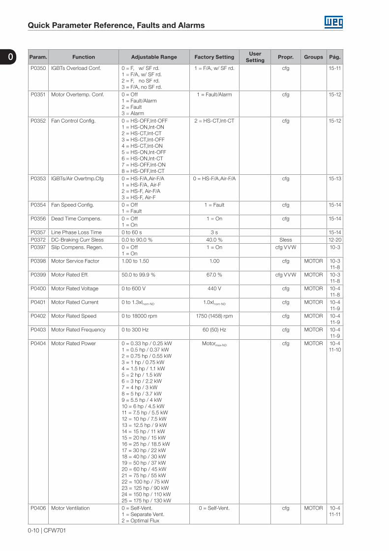
P0350 IGBTs Overload Conf. 0 = F, w/ SF rd.1 = F/A, w/ SF rd.2 = F, no SF rd.3 = F/A, no SF rd.
1 = F/A, w/ SF rd. cfg 15-11
P0351 Motor Overtemp. Conf. 0 = Off1 = Fault/Alarm2 = Fault3 = Alarm
1 = Fault/Alarm cfg 15-12
P0352 Fan Control Config. 0 = HS-OFF,Int-OFF1 = HS-ON,Int-ON2 = HS-CT,Int-CT3 = HS-CT,Int-OFF4 = HS-CT,Int-ON5 = HS-ON,Int-OFF6 = HS-ON,Int-CT7 = HS-OFF,Int-ON8 = HS-OFF,Int-CT
2 = HS-CT,Int-CT cfg 15-12
P0353 IGBTs/Air Overtmp.Cfg 0 = HS-F/A,Air-F/A1 = HS-F/A, Air-F2 = HS-F, Air-F/A3 = HS-F, Air-F
0 = HS-F/A,Air-F/A cfg 15-13
P0354 Fan Speed Config. 0 = Off1 = Fault
1 = Fault cfg 15-14
P0356 Dead Time Compens. 0 = Off1 = On
1 = On cfg 15-14
P0357 Line Phase Loss Time 0 to 60 s 3 s 15-14P0372 DC-Braking Curr Sless 0.0 to 90.0 % 40.0 % Sless 12-20P0397 Slip Compens. Regen. 0 = Off
1 = On1 = On cfg VVW 10-3
P0398 Motor Service Factor 1.00 to 1.50 1.00 cfg MOTOR 10-3 11-8
P0399 Motor Rated Eff. 50.0 to 99.9 % 67.0 % cfg VVW MOTOR 10-3 11-8
P0400 Motor Rated Voltage 0 to 600 V 440 V cfg MOTOR 10-4 11-8
P0401 Motor Rated Current 0 to 1.3xInom-ND 1.0xInom-ND cfg MOTOR 10-4 11-9
P0402 Motor Rated Speed 0 to 18000 rpm 1750 (1458) rpm cfg MOTOR 10-4 11-9
P0403 Motor Rated Frequency 0 to 300 Hz 60 (50) Hz cfg MOTOR 10-4 11-9
P0404 Motor Rated Power 0 = 0.33 hp / 0.25 kW1 = 0.5 hp / 0.37 kW2 = 0.75 hp / 0.55 kW3 = 1 hp / 0.75 kW4 = 1.5 hp / 1.1 kW5 = 2 hp / 1.5 kW6 = 3 hp / 2.2 kW7 = 4 hp / 3 kW8 = 5 hp / 3.7 kW9 = 5.5 hp / 4 kW10 = 6 hp / 4.5 kW11 = 7.5 hp / 5.5 kW12 = 10 hp / 7.5 kW13 = 12.5 hp / 9 kW14 = 15 hp / 11 kW15 = 20 hp / 15 kW16 = 25 hp / 18.5 kW17 = 30 hp / 22 kW18 = 40 hp / 30 kW19 = 50 hp / 37 kW20 = 60 hp / 45 kW21 = 75 hp / 55 kW22 = 100 hp / 75 kW23 = 125 hp / 90 kW24 = 150 hp / 110 kW25 = 175 hp / 130 kW
Motormax-ND cfg MOTOR 10-4 11-10
P0406 Motor Ventilation 0 = Self-Vent.1 = Separate Vent.2 = Optimal Flux
0 = Self-Vent. cfg MOTOR 10-4 11-11

0
Quick Parameter Reference, Faults and Alarms
CFW701 | 0-11
Param. Function Adjustable Range Factory SettingUser
SettingPropr. Groups Pág.
P0407 Motor Rated Power Fac 0.50 to 0.99 0.68 cfg V/F VVW
MOTOR 10-4 11-1119-7
P0408 Run Self-Tuning 0 = No1 = No Rotation2 = Run for Im
0 = No cfg VVW Vector
MOTOR 10-4 11-11 11-18
P0409 Stator Resistance 0.000 to 9.999 Ω 0.000 Ω cfg VVW Vector
MOTOR 10-4 11-11 11-19
P0410 Magnetization Current 0 to 1.25xInom-ND Imag-ND MOTOR 10-4 11-11 11-19
P0411 Leakage Inductance 0.00 to 99.99 0.00 cfg Vector MOTOR 11-11 11-20
P0412 Tr Time Constant 0.000 to 9.999 s 0.000 s Vector MOTOR 11-11 11-20
P0413 Tm Time Constant 0.00 to 99.99 s 0.00 s Vector MOTOR 11-11 11-21
P0510 Ind. Eng. Unit 1 0 = None1 = V2 = A3 = rpm4 = s5 = ms6 = None7 = m8 = None9 = None10 = %11 = °C12 = None13 = Hz14 = None15 = h16 = W17 = kW18 = None19 = None20 = min21 = °F22 = bar23 = mbar24 = psi25 = Pa26 = kPa27 = MPa28 = mwc29 = mca30 = gal31 = l32 = in33 = ft34 = m³35 = ft³36 = gal/s37 = gal/min38 = gal/h39 = l/s40 = l/min41 = l/h42 = m/s43 = m/min44 = m/h45 = ft/s46 = ft/min47 = ft/h48 = m³/s49 = m³/min50 = m³/h51 = ft³/s52 = ft³/min53 = ft³/h
22 = bar HMI 5-6

0
Quick Parameter Reference, Faults and Alarms
0-12 | CFW701
Param. Function Adjustable Range Factory SettingUser
SettingPropr. Groups Pág.
P0511 Ind. Decimal Point 1 0 = wxyz1 = wxy.z2 = wx.yz3 = w.xyz
1 = wxy.z HMI 5-7
P0512 Ind. Eng. Unit 2 See options in P0510 11 = °C HMI 5-8P0513 Ind. Decimal Point 2 0 = wxyz
1 = wxy.z2 = wx.yz3 = w.xyz
1 = wxy.z HMI 5-9
P0514 Ind. Eng. Unit 3 See options in P0510 10 = % HMI 5-10P0515 Ind. Decimal Point 3 0 = wxyz
1 = wxy.z2 = wx.yz3 = w.xyz
1 = wxy.z HMI 5-11
P0516 Ind. Eng. Unit 4 See options in P0510 13 = Hz HMI 5-12P0517 Ind. Decimal Point 4 0 = wxyz
1 = wxy.z2 = wx.yz3 = w.xyz
1 = wxy.z HMI 5-13
P0580 Fire Mode Configuration 0 = Off1 = On2 = On/P01343 = On/P05814 = On/Gen.Disable
0 = Off cfg 19-2
P0581 Fire Mode PID Setpoint -32768 to 32767 0 19-2P0582 Auto-Reset Configuration 0 = Limited
1 = Unlimited0 = Limited cfg 19-3
P0583 Bypass Mode Configuration 0 = Off1 = On/DIx2 = On/DIx+Fault
0 = Off cfg 19-6
P0584 Bypass Contactor Time 0.00 to 300.00 s 0.30 s 19-6P0585 Short Cycle Protection
Config.0 = Off1 = On
0 = Off cfg 19-8
P0586 Minimum RUN Time 0.00 to 650.00 s 5.00 s 19-9P0587 Minimum STOP Time 0.00 to 650.00 s 5.00 s 19-9P0588 Energy Saving Max.Torque 0 to 85 % 0 % cfg V/F 19-7P0589 Energy Saving Min. Mag. 40 to 80 % 40 % cfg V/F 19-7P0590 Energy Saving Min. Speed 360 to 18000 rpm 600 (525) rpm cfg V/F 19-8P0591 Energy Saving Histeresis 0 to 30 % 10 % cfg V/F 19-8P0680 Logical Status Bit 0...1 = Not Used
Bit 2 = Fire ModeBit 3 = BypassBit 4 = Quick Stop ONBit 5 = 2nd RampBit 6 = Config. ModeBit 7 = AlarmBit 8 = RunningBit 9 = EnabledBit 10 = ForwardBit 11 = JOGBit 12 = RemoteBit 13 = SubvoltageBit 14 = Not UsedBit 15 = Fault
ro NET 17-2
P0681 Speed in 13 bits -32768 to 32767 ro NET 17-2P0682 Serial Control Word Bit 0 = Ramp Enable
Bit 1 = General EnableBit 2 = Run ForwardBit 3 = JOG EnableBit 4 = RemoteBit 5 = 2nd RampBit 6 = Quick StopBit 7 = Fault ResetBit 8....12 = ReservedBit 13 = Internal PIDBit 14 = External PID 1Bit 15 = External PID 2
ro NET 17-2
0
Quick Parameter Reference, Faults and Alarms
CFW701 | 0-13
Param. Function Adjustable Range Factory SettingUser
SettingPropr. Groups Pág.
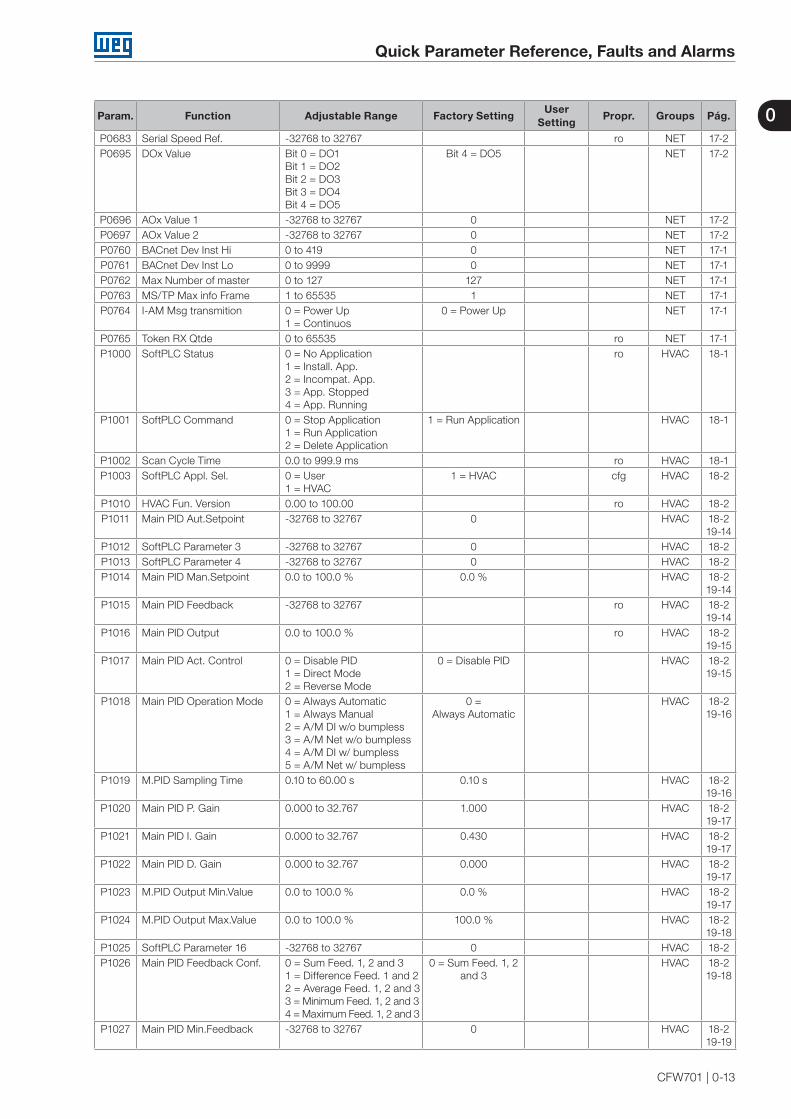
P0683 Serial Speed Ref. -32768 to 32767 ro NET 17-2P0695 DOx Value Bit 0 = DO1
Bit 1 = DO2Bit 2 = DO3Bit 3 = DO4Bit 4 = DO5
Bit 4 = DO5 NET 17-2
P0696 AOx Value 1 -32768 to 32767 0 NET 17-2P0697 AOx Value 2 -32768 to 32767 0 NET 17-2P0760 BACnet Dev Inst Hi 0 to 419 0 NET 17-1P0761 BACnet Dev Inst Lo 0 to 9999 0 NET 17-1P0762 Max Number of master 0 to 127 127 NET 17-1P0763 MS/TP Max info Frame 1 to 65535 1 NET 17-1P0764 I-AM Msg transmition 0 = Power Up
1 = Continuos0 = Power Up NET 17-1
P0765 Token RX Qtde 0 to 65535 ro NET 17-1P1000 SoftPLC Status 0 = No Application
1 = Install. App.2 = Incompat. App.3 = App. Stopped4 = App. Running
ro HVAC 18-1
P1001 SoftPLC Command 0 = Stop Application1 = Run Application2 = Delete Application
1 = Run Application HVAC 18-1
P1002 Scan Cycle Time 0.0 to 999.9 ms ro HVAC 18-1P1003 SoftPLC Appl. Sel. 0 = User
1 = HVAC1 = HVAC cfg HVAC 18-2
P1010 HVAC Fun. Version 0.00 to 100.00 ro HVAC 18-2P1011 Main PID Aut.Setpoint -32768 to 32767 0 HVAC 18-2
19-14P1012 SoftPLC Parameter 3 -32768 to 32767 0 HVAC 18-2P1013 SoftPLC Parameter 4 -32768 to 32767 0 HVAC 18-2P1014 Main PID Man.Setpoint 0.0 to 100.0 % 0.0 % HVAC 18-2
19-14P1015 Main PID Feedback -32768 to 32767 ro HVAC 18-2
19-14P1016 Main PID Output 0.0 to 100.0 % ro HVAC 18-2
19-15P1017 Main PID Act. Control 0 = Disable PID
1 = Direct Mode2 = Reverse Mode
0 = Disable PID HVAC 18-219-15
P1018 Main PID Operation Mode 0 = Always Automatic1 = Always Manual2 = A/M DI w/o bumpless3 = A/M Net w/o bumpless4 = A/M DI w/ bumpless5 = A/M Net w/ bumpless
0 = Always Automatic
HVAC 18-219-16
P1019 M.PID Sampling Time 0.10 to 60.00 s 0.10 s HVAC 18-219-16
P1020 Main PID P. Gain 0.000 to 32.767 1.000 HVAC 18-219-17
P1021 Main PID I. Gain 0.000 to 32.767 0.430 HVAC 18-219-17
P1022 Main PID D. Gain 0.000 to 32.767 0.000 HVAC 18-219-17
P1023 M.PID Output Min.Value 0.0 to 100.0 % 0.0 % HVAC 18-219-17
P1024 M.PID Output Max.Value 0.0 to 100.0 % 100.0 % HVAC 18-219-18
P1025 SoftPLC Parameter 16 -32768 to 32767 0 HVAC 18-2P1026 Main PID Feedback Conf. 0 = Sum Feed. 1, 2 and 3
1 = Difference Feed. 1 and 22 = Average Feed. 1, 2 and 33 = Minimum Feed. 1, 2 and 34 = Maximum Feed. 1, 2 and 3
0 = Sum Feed. 1, 2 and 3
HVAC 18-219-18
P1027 Main PID Min.Feedback -32768 to 32767 0 HVAC 18-219-19
0
Quick Parameter Reference, Faults and Alarms
0-14 | CFW701
Param. Function Adjustable Range Factory SettingUser
SettingPropr. Groups Pág.
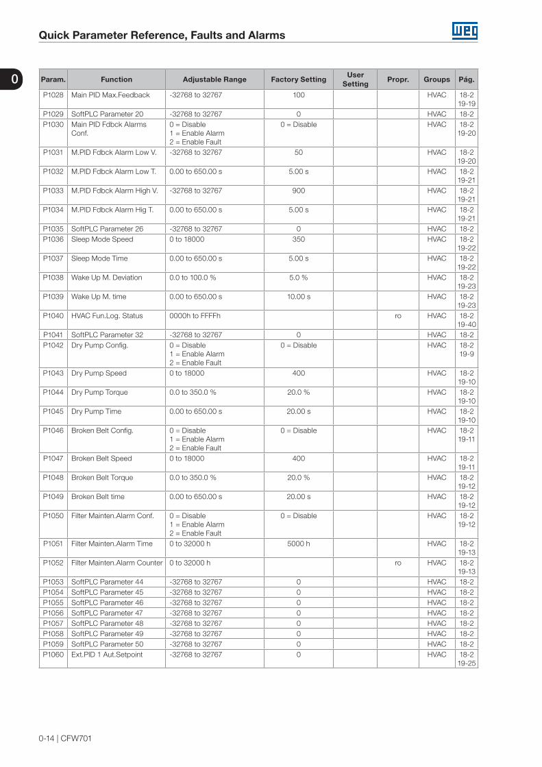
P1028 Main PID Max.Feedback -32768 to 32767 100 HVAC 18-219-19
P1029 SoftPLC Parameter 20 -32768 to 32767 0 HVAC 18-2P1030 Main PID Fdbck Alarms
Conf.0 = Disable1 = Enable Alarm2 = Enable Fault
0 = Disable HVAC 18-219-20
P1031 M.PID Fdbck Alarm Low V. -32768 to 32767 50 HVAC 18-219-20
P1032 M.PID Fdbck Alarm Low T. 0.00 to 650.00 s 5.00 s HVAC 18-219-21
P1033 M.PID Fdbck Alarm High V. -32768 to 32767 900 HVAC 18-219-21
P1034 M.PID Fdbck Alarm Hig T. 0.00 to 650.00 s 5.00 s HVAC 18-219-21
P1035 SoftPLC Parameter 26 -32768 to 32767 0 HVAC 18-2P1036 Sleep Mode Speed 0 to 18000 350 HVAC 18-2
19-22P1037 Sleep Mode Time 0.00 to 650.00 s 5.00 s HVAC 18-2
19-22P1038 Wake Up M. Deviation 0.0 to 100.0 % 5.0 % HVAC 18-2
19-23P1039 Wake Up M. time 0.00 to 650.00 s 10.00 s HVAC 18-2
19-23P1040 HVAC Fun.Log. Status 0000h to FFFFh ro HVAC 18-2
19-40P1041 SoftPLC Parameter 32 -32768 to 32767 0 HVAC 18-2P1042 Dry Pump Config. 0 = Disable
1 = Enable Alarm2 = Enable Fault
0 = Disable HVAC 18-2 19-9
P1043 Dry Pump Speed 0 to 18000 400 HVAC 18-219-10
P1044 Dry Pump Torque 0.0 to 350.0 % 20.0 % HVAC 18-219-10
P1045 Dry Pump Time 0.00 to 650.00 s 20.00 s HVAC 18-219-10
P1046 Broken Belt Config. 0 = Disable1 = Enable Alarm2 = Enable Fault
0 = Disable HVAC 18-219-11
P1047 Broken Belt Speed 0 to 18000 400 HVAC 18-219-11
P1048 Broken Belt Torque 0.0 to 350.0 % 20.0 % HVAC 18-219-12
P1049 Broken Belt time 0.00 to 650.00 s 20.00 s HVAC 18-219-12
P1050 Filter Mainten.Alarm Conf. 0 = Disable1 = Enable Alarm2 = Enable Fault
0 = Disable HVAC 18-219-12
P1051 Filter Mainten.Alarm Time 0 to 32000 h 5000 h HVAC 18-219-13
P1052 Filter Mainten.Alarm Counter 0 to 32000 h ro HVAC 18-219-13
P1053 SoftPLC Parameter 44 -32768 to 32767 0 HVAC 18-2P1054 SoftPLC Parameter 45 -32768 to 32767 0 HVAC 18-2P1055 SoftPLC Parameter 46 -32768 to 32767 0 HVAC 18-2P1056 SoftPLC Parameter 47 -32768 to 32767 0 HVAC 18-2P1057 SoftPLC Parameter 48 -32768 to 32767 0 HVAC 18-2P1058 SoftPLC Parameter 49 -32768 to 32767 0 HVAC 18-2P1059 SoftPLC Parameter 50 -32768 to 32767 0 HVAC 18-2P1060 Ext.PID 1 Aut.Setpoint -32768 to 32767 0 HVAC 18-2
19-25

0
Quick Parameter Reference, Faults and Alarms
CFW701 | 0-15
Param. Function Adjustable Range Factory SettingUser
SettingPropr. Groups Pág.
P1061 Ext.PID 1 Man.Setpoint 0.0 to 100.0 % 0.0 % HVAC 18-219-25
P1062 Ext.PID 1 Feedback -32768 to 32767 ro HVAC 18-219-26
P1063 Ext.PID 1 Output 0.0 to 100.0 % ro HVAC 18-219-26
P1064 Ext.PID 1 Act.Control 0 = Disable PID1 = Direct Mode2 = Reverse Mode
0 = Disable PID HVAC 18-219-26
P1065 Ext.PID1 Operation Mode 0 = Always Automatic1 = Always Manual2 = A/M DI w/o bumpless3 = A/M Net w/o bumpless4 = A/M DI w/ bumpless5 = A/M Net w/ bumpless
0 = Always Automatic
HVAC 18-219-27
P1066 Ext.PID1 Sampling Time 0.10 to 60.00 s 0.10 s HVAC 18-219-28
P1067 Ext.PID 1 P. Gain 0.000 to 32.767 1.000 HVAC 18-219-28
P1068 Ext.PID 1 I. Gain 0.000 to 32.767 0.430 HVAC 18-219-28
P1069 Ext.PID 1 D. Gain 0.000 to 32.767 0.000 HVAC 18-219-28
P1070 Ext.PID1 Output Min.Value 0.0 to 100.0 % 0.0 % HVAC 18-219-29
P1071 Ext.PID1 Output Max.Value 0.0 to 100.0 % 100.0 % HVAC 18-219-29
P1072 SoftPLC Parameter 63 -32768 to 32767 0 HVAC 18-2P1073 Ext.PID1 Min.Feedback -32768 to 32767 0 HVAC 18-2
19-29P1074 Ext.PID1 Max.Feedback -32768 to 32767 1000 HVAC 18-2
19-30P1075 Ext.PID1 Fdbck Alarms
Conf.0 = Disable1 = Enable Alarm2 = Enable Fault
0 = Disable HVAC 18-219-30
P1076 Ext.PID1 Fdbck Alarm Low V. -32768 to 32767 2 HVAC 18-219-31
P1077 Ext.PID1 Fdbck Alarm Low T. 0.00 to 650.00 s 5.00 s HVAC 18-219-31
P1078 Ext.PID1 Fdbck Alarm High V. -32768 to 32767 900 HVAC 18-219-31
P1079 Ext.PID1 Fdbck Alarm Hig T. 0.00 to 650.00 s 5.00 s HVAC 18-219-32
P1080 Ext.PID 2 Aut.Setpoint -32768 to 32767 0 HVAC 18-219-33
P1081 Ext.PID 2 Man.Setpoint 0.0 to 100.0 % 0.0 % HVAC 18-219-33
P1082 Ext.PID 2 Feedback -32768 to 32767 ro HVAC 18-219-33
P1083 Ext.PID 2 Output 0.0 to 100.0 % ro HVAC 18-219-34
P1084 Ext.PID 2 Act.Control 0 = Disable PID1 = Direct Mode2 = Reverse Mode
0 = Disable PID HVAC 18-219-34
P1085 Ext.PID2 Operation Mode 0 = Always Automatic1 = Always Manual2 = A/M DI w/o bumpless3 = A/M Net w/o bumpless4 = A/M DI w/ bumpless5 = A/M Net w/ bumpless
0 = Always Automatic
HVAC 18-219-35

0
Quick Parameter Reference, Faults and Alarms
0-16 | CFW701
Param. Function Adjustable Range Factory SettingUser
SettingPropr. Groups Pág.
P1086 Ext.PID2 Sampling Time 0.10 to 60.00 s 0.10 s HVAC 18-219-35
P1087 Ext.PID 2 P. Gain 0.000 to 32.767 1.000 HVAC 18-219-36
P1088 Ext.PID 2 I. Gain 0.000 to 32.767 0.430 HVAC 18-219-36
P1089 Ext.PID 2 D. Gain 0.000 to 32.767 0.000 HVAC 18-219-36
P1090 Ext.PID2 Output Min.Value 0.0 to 100.0 % 0.0 % HVAC 18-219-36
P1091 Ext.PID2 Output Max.Value 0.0 to 100.0 % 100.0 % HVAC 18-219-37
P1092 SoftPLC Parameter 83 -32768 to 32767 0 HVAC 18-2P1093 Ext.PID2 Min.Feedback -32768 to 32767 0 HVAC 18-2
19-37P1094 Ext.PID2 Max.Feedback -32768 to 32767 1000 HVAC 18-2
19-37P1095 Ext.PID2 Fdbck Alarms
Conf.0 = Disable1 = Enable Alarm2 = Enable Fault
0 = Disable HVAC 18-219-38
P1096 Ext.PID2 Fdbck Alarm Low V. -32768 to 32767 2 HVAC 18-219-38
P1097 Ext.PID2 Fdbck Alarm Low T. 0.00 to 650.00 s 5.00 s HVAC 18-219-39
P1098 Ext.PID2 Fdbck Alarm High V. -32768 to 32767 900 HVAC 18-219-39
P1099 Ext.PID2 Fdbck Alarm Hig T. 0.00 to 650.00 s 5.00 s HVAC 18-219-39
Notes:ro = Read-only parameter.rw = Reading/writing parameter.cfg = Configuration parameter, it can be changed only with stopped motor.V/f = Parameter available in V/f mode.Adj = Parameter available only in adjustable V/f mode.VVW = Parameter available in VVW mode.Vector = Parameter available in vector mode.Sless = Parameter available only in sensorless mode.

0
Quick Parameter Reference, Faults and Alarms
CFW701 | 0-17
Fault/Alarm Description Possible Causes
F006:Input Voltage Imbalance or Phase Loss
The mains voltage imbalance is too high or phase loss at the supply line has occurred.Note:- This fault may not occur if the load at the motor shaft is too low or nonexistent.P0357 sets the time for the trip, and P0357 = 0 disables this fault.
A Phase Loss at the inverter input. The input voltage imbalance is > 5 %.
F021:DC Link Undervoltage
A DC link undervoltage condition has occurred. The input voltage is too low and the DC link voltage dropped below the minimum permitted value (monitor the P0004 parameter value): Ud < 223 V - 200-240 V three-phase input voltage; Ud < 170 V - 200-240 V single-phase input voltage (CFW701XXXXS2 or CFW701XXXXB2 models) (P0296 = 0); Ud < 385 V - 380 V input voltage (P0296 = 1); Ud < 405 V - 400-415 V input voltage (P0296 = 2); Ud < 446 V - 440-460 V input voltage (P0296 = 3); Ud < 487 V - 480 V input voltage (P0296 = 4);Ud < 530 V - input voltage 500-525 V (P0296=5);Ud < 580 V - input voltage 500 - 575 V (P0296=6);Ud < 605 V - input voltage 600 V (P0296=7).
Phase loss at the inverter input. Pre-charge circuit failure. Parameter P0296 was set to a value higher than the
power supply rated voltage.
F022: DC Link Overvoltage
A DC link overvoltage condition has occurred. Too high input voltage, resulting in a DC link voltage higher than the maximum permitted value: Ud > 400 V - 220-230 V models (P0296 = 0); Ud > 800 V - 380-480 V models (P0296 = 1, 2, 3, or 4);Ud > 1000 V - 500-600 V models (P0296=5, 6 or 7).
The inertia of the driven-load is too high or the deceleration time is too short.
The parameter P0151, P0153 or P0185 setting is too high.
A046: High Load at the Motor
It is the motor overload alarm.Note:It can be disabled by setting P0348 = 0 or 2.
The settings of P0156, P0157 and P0158 are too low for the used motor.
There is excessive load at the motor shaft.
A047: IGBT Overload Alarm
It is the IGBT overload alarm.Note:It can be disabled by setting P0350 = 0 or 2.
The inverter output current is too high.
F048: IGBT Overload Fault
It is the IGBT overload fault. The inverter output current is too high.
A050: IGBT High Temperature
The NTC temperature sensors located in the IGBTs detected a high temperature alarm. Note: It can be disabled by setting P0353 = 2 or 3.
High surrounding air temperature (>50 °C (122 °F)) and high output current.
Blocked or defective fan. Very dirty heatsink.
F051: IGBT Overtemperature
The NTC temperature sensors located in the IGBTs detected a high temperature fault.
F070: Overcurrent/Short-circuit
An overcurrent or a short-circuit at the output, at the DC link or at the braking resistor, has occurred.
Short-circuit between two motor phases. Short-circuit between the dynamic braking resistor
connection cables. Shorted IGBT modules.
F071: Output Overcurrent
An output overcurrent has occurred. Excessive load inertia or too short acceleration ramp. P0135, or P0169 and P0170 settings are too high.
F072: Motor Overload
The motor overload protection has tripped.Note:It can be disabled by setting P0348 = 0 or 3.
The settings of P0156, P0157 and P0158 are too low for the used motor.
There is excessive load at the motor shaft.F074: Ground Fault
A ground fault occurred either in the cable between the inverter and the motor or in the motor itself. Note: It can be disabled by setting P0343 = 0.
Short-circuit to the ground in one or more output phases. Motor cable capacitance is too large, resulting in current
peaks at the output.

0
Quick Parameter Reference, Faults and Alarms
0-18 | CFW701
Fault/Alarm Description Possible Causes
F078: Motor Overtemperature
Fault related to the PTC temperature sensor installed in the motor. Note:- It can be disabled by setting P0351 = 0 or 3.- An analog input and an analog output must be set for the PTC function.
Excessive load at the motor shaft. Severe duty cycle (too many starts / stops per minute). Too high surrounding air temperature. Loose connection or short-circuit (resistance < 100 Ω) in
the wiring connected to the motor thermistors. Not installed motor thermistors. Blocked motor shaft.
F080: CPU Watchdog
Microcontroller watchdog fault. Electrical noise.
F084: Auto-Diagnosis Fault
Auto-Diagnosis Fault. Defect in the inverter internal circuitry. Firmware incompatible with an accessory.
A090: External Alarm
External alarm monitored through a digital input. Note: It is necessary to program a digital input for “No external alarm”.
A digital input (DI1 to DI8) programmed for “No external alarm” is open.
F091: External Fault
External fault monitored through a digital input. Note: It is necessary to program a digital input for “No external fault”.
A digital input (DI1 to DI8) programmed for “No external fault” is open.
A098: Activate General Enable
General enable signal is missing during the self-tuning.
The digital input programmed for “General Enable” is open.
F099: Invalid Current Offset
The current measurement circuit is presenting an abnormal value for null current.
Defect in the inverter internal circuitry.
A110: High Motor Temperature
Fault detected through PTC type temperature sensors installed in the motor.Note:- It can be disabled by setting P0351 = 0 or 2.- An analog input and an analog output must be set for the PTC function.
Excessive load at the motor shaft. Severe duty cycle (too many starts / stops per minute). Too high surrounding air temperature. Not installed motor thermistors. Blocked motor shaft.
A128: Serial Communication Timeout
It indicates that the inverter stopped receiving valid telegrams during a certain period.Note:It can be disabled by setting P0314 = 0.0 s
Check the wiring and the ground installation. Make sure that the inverter has sent a new message
within the time interval set at P0314.
F150: Motor Overspeed
Overspeed fault.It trips when the actual speed exceeds the value
of P0134 x (100 % + P0132) 100%
for more than 20 ms.
Wrong settings of P0161 and/or P0162. Problem with a hoist-type load.
F151: FLASH Memory Module Fault
FLASH Memory Module (MMF-01) fault. Defective FLASH memory module. Check the connection of the FLASH memory module.
A152: High Internal Air Temperature
This alarm indicates that the internal air temperature is too high.Note:It can be disabled by setting P0353 = 1 or 3.
High surrounding air temperature (>50 °C (122 °F)) and high output current.
Defective internal fan (if existent). High temperature (> 45 ºC) inside the cabinet.
F153: Internal Air Overtemperature
It indicates internal air overtemperature fault. High surrounding air temperature (>50 °C (122 °F)) and high output current.
Defective internal fan (if existent).
F156: Undertemperature
The temperature sensors located in the IGBTs or in the rectifier detected a low temperature, below -30 °C ( -22 °F), fault.
Surrounding air temperature ≤ -30 °C (-22 °F).
F157: Parameter Table Data Loss
There was a problem during the initialization, during the parameter table loading routine. Some recent parameter modifications may have been lost.
The control was switched off very fast while a parameter was being modified.
F158: Parameter Table Fault
There was a problem during the initialization, during the parameter table loading routine. All the parameters were lost and the factory settings were loaded.
Firmware updating fault. Defective control board.
F160:Safety Stop Relays
Safety stop relay fault. One of the relays is defective or it does not have +24 V applied to its coil.
A163:AI1 Broken Cable
It indicates that the AI1 current (4-20 mA or 20-4 mA) reference is out of the 4 to 20 mA range.
Broken AI1 cable. Bad contact at the connection of the signal to the
terminal strip.
A164:AI2 Broken Cable
It indicates that the AI2 current (4-20 mA or 20-4 mA) reference is out of the 4 to 20 mA range.
Broken AI2 cable. Bad contact at the connection of the signal to the
terminal strip.
0
Quick Parameter Reference, Faults and Alarms
CFW701 | 0-19
Fault/Alarm Description Possible Causes
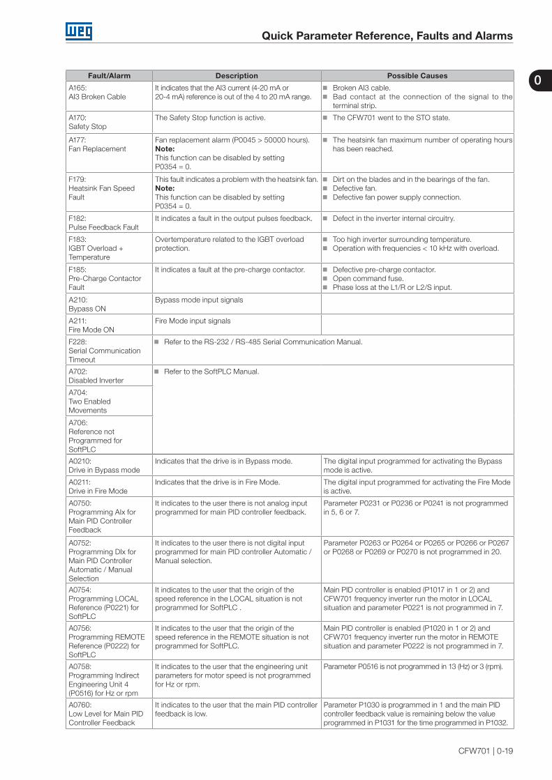
A165:AI3 Broken Cable
It indicates that the AI3 current (4-20 mA or20-4 mA) reference is out of the 4 to 20 mA range.
Broken AI3 cable. Bad contact at the connection of the signal to the
terminal strip.
A170:Safety Stop
The Safety Stop function is active. The CFW701 went to the STO state.
A177: Fan Replacement
Fan replacement alarm (P0045 > 50000 hours). Note: This function can be disabled by setting P0354 = 0.
The heatsink fan maximum number of operating hours has been reached.
F179: Heatsink Fan Speed Fault
This fault indicates a problem with the heatsink fan. Note: This function can be disabled by setting P0354 = 0.
Dirt on the blades and in the bearings of the fan. Defective fan. Defective fan power supply connection.
F182: Pulse Feedback Fault
It indicates a fault in the output pulses feedback. Defect in the inverter internal circuitry.
F183: IGBT Overload + Temperature
Overtemperature related to the IGBT overload protection.
Too high inverter surrounding temperature. Operation with frequencies < 10 kHz with overload.
F185:Pre-Charge Contactor Fault
It indicates a fault at the pre-charge contactor. Defective pre-charge contactor. Open command fuse. Phase loss at the L1/R or L2/S input.
A210:Bypass ON
Bypass mode input signals
A211:Fire Mode ON
Fire Mode input signals
F228:Serial Communication Timeout
Refer to the RS-232 / RS-485 Serial Communication Manual.
A702:Disabled Inverter
Refer to the SoftPLC Manual.
A704:Two Enabled Movements
A706:Reference not Programmed for SoftPLC
A0210:Drive in Bypass mode
Indicates that the drive is in Bypass mode. The digital input programmed for activating the Bypass mode is active.
A0211:Drive in Fire Mode
Indicates that the drive is in Fire Mode. The digital input programmed for activating the Fire Mode is active.
A0750:Programming AIx for Main PID Controller Feedback
It indicates to the user there is not analog input programmed for main PID controller feedback.
Parameter P0231 or P0236 or P0241 is not programmed in 5, 6 or 7.
A0752:Programming DIx for Main PID Controller Automatic / Manual Selection
It indicates to the user there is not digital input programmed for main PID controller Automatic / Manual selection.
Parameter P0263 or P0264 or P0265 or P0266 or P0267 or P0268 or P0269 or P0270 is not programmed in 20.
A0754:Programming LOCAL Reference (P0221) for SoftPLC
It indicates to the user that the origin of the speed reference in the LOCAL situation is not programmed for SoftPLC .
Main PID controller is enabled (P1017 in 1 or 2) and CFW701 frequency inverter run the motor in LOCAL situation and parameter P0221 is not programmed in 7.
A0756:Programming REMOTE Reference (P0222) for SoftPLC
It indicates to the user that the origin of the speed reference in the REMOTE situation is not programmed for SoftPLC.
Main PID controller is enabled (P1020 in 1 or 2) and CFW701 frequency inverter run the motor in REMOTE situation and parameter P0222 is not programmed in 7.
A0758:Programming Indirect Engineering Unit 4 (P0516) for Hz or rpm
It indicates to the user that the engineering unit parameters for motor speed is not programmed for Hz or rpm.
Parameter P0516 is not programmed in 13 (Hz) or 3 (rpm).
A0760:Low Level for Main PID Controller Feedback
It indicates to the user that the main PID controller feedback is low.
Parameter P1030 is programmed in 1 and the main PID controller feedback value is remaining below the value programmed in P1031 for the time programmed in P1032.

0
Quick Parameter Reference, Faults and Alarms
0-20 | CFW701
Fault/Alarm Description Possible Causes
F0761:Low Level for Main PID Controller Feedback
It indicates to the user that the main PID controller feedback is low.
Parameter P1030 is programmed in 2 and the main PID controller feedback value is remaining below the value programmed in P1031 for the time programmed in P1032.
A0762:High Level for Main PID Controller Feedback
It indicates to the user that the main PID controller feedback is high.
Parameter P1030 is programmed in 1 and the main PID controller feedback value is remaining above the value programmed in P1033 for the time programmed in P1034.
F0763:High Level for Main PID Controller Feedback
It indicates to the user that the main PID controller feedback is high.
Parameter P1030 is programmed in 2 and the main PID controller feedback value is remaining above the value programmed in P1033 for the time programmed in P1034.
A0764:CFW701 in Sleep Mode
It indicates to the user that the CFW701 frequency inverter is in sleep mode.
Main PID controller is enabled and in automatic mode and the motor speed is remaining below the speed value programmed in P1036 for the time programmed in P1037.
A0766:Dry Pump Detected
It indicates to the user that the dry pump condition was detected for the pump driven by CFW701 frequency inverter.
Parameter P1042 is programmed in 1 and the pump driven by CFW701 frequency inverter is running faster than speed programmed in P1043 and the motor torque is remaining below the torque value programmed in P1044 for the time programmed in P1045.
F0767:Dry Pump Detected
It indicates to the user that the dry pump condition was detected for the pump driven by CFW701 frequency inverter.
Parameter P1042 is programmed in 2 and the pump driven by CFW701 frequency inverter is running faster than speed programmed in P1043 and the motor torque is remaining below the torque value programmed in P1044 for the time programmed in P1045.
A0768:Broken Belt Detected
It indicates to the user that the broken belt condition was detected for the motor driven by CFW701 frequency inverter.
Parameter P1046 is programmed in 1 and the motor driven by CFW701 frequency inverter is running faster than speed programmed in P1047 and the motor torque is remaining below the torque value programmed in P1048 for the time programmed in P1049.
F0769:Broken Belt Detected
It indicates to the user that the broken belt condition was detected for the motor driven by CFW701 frequency inverter.
Parameter P1046 is programmed in 2 and the motor driven by CFW701 frequency inverter is running faster than speed programmed in P1047 and the motor torque is remaining below the torque value programmed in P1048 for the time programmed in P1049.
A0770:Filter Maintenance
It indicates to the user that the need to change the filter system.
Parameter P1050 is programmed in 1 and the operation time of motor driven by CFW701 frequency inverter displayed in P1052 is greater than the time programmed in P1051.
F0771:Filter Maintenance
It indicates to the user that the need to change the filter system.
Parameter P1050 is programmed in 2 and the operation time of motor driven by CFW701 frequency inverter displayed in P1052 is greater than the time programmed in P1051.
A0780:Programming AIx for External PID Controller 1 Feedback
It indicates to the user there is not analog input programmed for external PID controller 1 feedback.
Parameter P0231 or P0236 or P0241 is not programmed in 8.
A0782:Programming DIx for External PID Controller 1 Automatic / Manual Selection
It indicates to the user there is not digital input programmed for external PID controller 1 Automatic / Manual selection.
Parameter P0263 or P0264 or P0265 or P0266 or P0267 or P0268 or P0269 or P0270 is not programmed in 21.
A0784:Programming AOx for External PID Controller 1 Output
It indicates to the user there is not analog output programmed for external PID controller 1 output.
Parameter P0251 or P0254 is not programmed in 16.
A0786:Low Level for External PID Controller 1 Feedback
It indicates to the user that the external PID controller 1 feedback is low.
Parameter P1075 is programmed in 1 and the external PID controller 1 feedback value is remaining below the value programmed in P1076 for the time programmed in P1077.
F0787:Low Level for External PID Controller 1 Feedback
It indicates to the user that the external PID controller 1 feedback is low.
Parameter P1075 is programmed in 2 and the External PID Controller 1 Feedback value is remaining below the value programmed in P1076 for the time programmed in P1077.
A0788:High Level for External PID Controller 1 Feedback
It indicates to the user that the external PID controller 1 feedback is high.
Parameter P1075 is programmed in 1 and the external PID controller 1 feedback value is remaining above the value programmed in P1078 for the time programmed in P1079.
F0789:High Level for External PID Controller 1 Feedback
It indicates to the user that the external PID controller 1 feedback is high.
Parameter P1075 is programmed in 2 and the external PID controller 1 feedback value is remaining above the value programmed in P1078 for the time programmed in P1079.
0
Quick Parameter Reference, Faults and Alarms
CFW701 | 0-21
Fault/Alarm Description Possible Causes
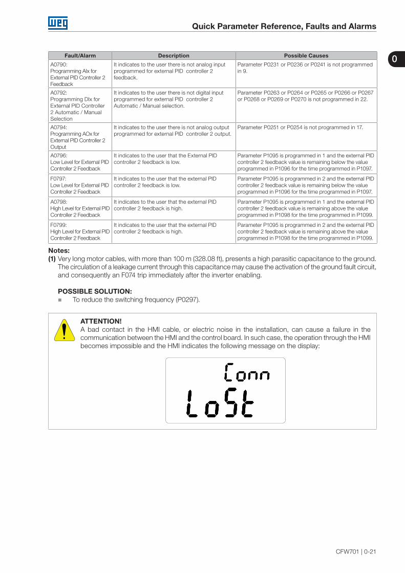
A0790:Programming AIx for External PID Controller 2 Feedback
It indicates to the user there is not analog input programmed for external PID controller 2 feedback.
Parameter P0231 or P0236 or P0241 is not programmed in 9.
A0792:Programming DIx for External PID Controller 2 Automatic / Manual Selection
It indicates to the user there is not digital input programmed for external PID controller 2 Automatic / Manual selection.
Parameter P0263 or P0264 or P0265 or P0266 or P0267 or P0268 or P0269 or P0270 is not programmed in 22.
A0794:Programming AOx for External PID Controller 2 Output
It indicates to the user there is not analog output programmed for external PID controller 2 output.
Parameter P0251 or P0254 is not programmed in 17.
A0796:Low Level for External PID Controller 2 Feedback
It indicates to the user that the External PID controller 2 feedback is low.
Parameter P1095 is programmed in 1 and the external PID controller 2 feedback value is remaining below the value programmed in P1096 for the time programmed in P1097.
F0797:Low Level for External PID Controller 2 Feedback
It indicates to the user that the external PID controller 2 feedback is low.
Parameter P1095 is programmed in 2 and the external PID controller 2 feedback value is remaining below the value programmed in P1096 for the time programmed in P1097.
A0798:High Level for External PID Controller 2 Feedback
It indicates to the user that the external PID controller 2 feedback is high.
Parameter P1095 is programmed in 1 and the external PID controller 2 feedback value is remaining above the value programmed in P1098 for the time programmed in P1099.
F0799:High Level for External PID Controller 2 Feedback
It indicates to the user that the external PID controller 2 feedback is high.
Parameter P1095 is programmed in 2 and the external PID controller 2 feedback value is remaining above the value programmed in P1098 for the time programmed in P1099.
Notes:(1) Very long motor cables, with more than 100 m (328.08 ft), presents a high parasitic capacitance to the ground.
The circulation of a leakage current through this capacitance may cause the activation of the ground fault circuit, and consequently an F074 trip immediately after the inverter enabling.
POSSIBLE SOLUTION: To reduce the switching frequency (P0297).
ATTENTION!A bad contact in the HMI cable, or electric noise in the installation, can cause a failure in the communication between the HMI and the control board. In such case, the operation through the HMI becomes impossible and the HMI indicates the following message on the display:

0
Quick Parameter Reference, Faults and Alarms
0-22 | CFW701

1
Safety Notices
CFW701 | 1-1
1 SAFETY NOTICES
This Manual contains the information necessary for the correct use of the CFW701 Frequency Inverter.
It has been developed to be used by qualified personnel with suitable training or technical qualification for operating this type of equipment.
1.1 SAFETY NOTICES IN THIS MANUAL
The following safety notices are used in this manual:
DANGER!The procedures recommended in this warning have the purpose of protecting the user against dead, serious injuries and considerable material damage.
ATTENTION!The procedures recommended in this warning have the purpose of avoiding material damage.
NOTE!The information mentioned in this warning is important for the proper understanding and good operation of the product.
1.2 SAFETY NOTICES ON THE PRODUCT
The following symbols are attached to the product, serving as safety notices:
High voltages are present.
Components sensitive to electrostatic discharge.Do not touch them.
Mandatory connection to the protective ground (PE).
Connection of the shield to the ground.
Hot surface.

1
Safety Notices
1-2 | CFW701
1.3 PRELIMINARY RECOMMENDATIONS
DANGER!Only qualified personnel familiar with the CFW701 Frequency Inverter and associated equipment should plan or implement the installation, start-up and subsequent maintenance of this equipment.
These personnel must follow all the safety instructions included in this manual and/or defined by local regulations.
Failure to comply with these instructions may result in life threatening and/or equipment damage.
NOTE!For the purposes of this manual, qualified personnel are those trained to be able to:
1. Install, ground, energize and operate the CFW701 according to this manual and the effective legal safety procedures.
2. Use protection equipment according to the established standards.
3. Give first aid services.
DANGER!Always disconnect the input power before touching any electrical component associated to the inverter.
Many components can remain charged with high voltages or remain in movement (fans) even after that AC power is disconnected or switched off.
Wait at least 10 minutes to assure a total discharge of the capacitors.
Always connect the equipment frame to the protection earth (PE) at the suitable connection point.
ATTENTION!Electronic boards have components sensitive to electrostatic discharges. Do not touch directly on components or connectors. If necessary, touch the grounded metallic frame before or use an adequate grounded wrist strap.
Do not perform any high pot tests with the inverter!If it is necessary consult WEG.
NOTE!Frequency inverter may interfere with other electronic equipment. In order to reduce these effects, take the precautions recommended in the chapter 3 - Installation and Connection, of the user's manual.
NOTE!Read the user's manual completely before installing or operating the inverter.
2
General Information
CFW701 | 2-1
2 GENERAL INFORMATION
2.1 ABOUT THIS MANUAL
This manual presents the necessary information for the configuration of all of the functions and parameters of the CFW701 Frequency Inverter. This manual must be used together with the CFW701 user's manual.
The text intents to supply additional information to facilitate the use and programming of the CFW701 in specific applications.
2.2 TERMINOLOGY AND DEFINITIONS
2.2.1 Terms and Definitions Used in the Manual
Normal Duty Cycle (ND): It is the inverter operation regimen that defines the maximum current value for continuous operation Inom-ND and overload of 110 % during 1 minute. It is selected by programming P0298 (Application)=0 (Normal Duty – ND). It must be used for driving motors that are not subject in that application to high torques in relation to their rated torque, when operating in permanent regimen, during start, acceleration or deceleration.
Inom-ND: Inverter rated current for use with normal overload regimen (ND=Normal Duty). Overload: 1.1 x Inom-ND / 1 minute.
Heavy Duty Cycle (HD): It is the inverter operation regimen that defines the maximum current value for continuous operation Inom-HD and overload of 150 % during 1 minute. It is selected by programming P0298 (Application)=1 (Heavy Duty (HD)). It must be used for driving motors that are subject in that application to high overload torques in relation to their rated torque, when operating in constant speed, during start, acceleration or deceleration.
Inom-HD: Inverter rated current for use with heavy overload regimen (HD=Heavy Duty).Overload: 1.5 x Inom-HD / 1 minute.
Rectifier: The input circuit of the inverters that converts the input AC voltage into DC. It is formed by power diodes.
Pre-charge Circuit: It charges the DC Link capacitors with a limited current, thus avoiding current peaks when powering the inverter.
DC Link: This is the inverter intermediate circuit, with DC voltage and current, obtained from the rectification of the AC supply voltage, or from an external source; it supplies the output IGBTs inverter bridge.
U, V and W Arm: It is a set of two IGBTs of the phases U, V and W at the inverter output.
IGBT: “Insulated Gate Bipolar Transistor”; It is the basic component of the output inverter bridge. It operates like an electronic switch in the saturated (closed switch) and cut (open switch) modes.
Braking IGBT: Operates as a switch for the activation of the braking resistor. It is commanded by the DC Link level.
PTC: It’s a resistor whose resistance value in ohms increases proportionally to the increase of the temperature; it is used as a temperature sensor in motors.
NTC: It’s a resistor whose resistance value in ohms decreases proportionally to the temperature increase; it is used as a temperature sensor in power modules.
Keypad (HMI): Human-Machine Interface; It is the device that allows the control of the motor, the visualization and the modification of the inverter parameters. It presents keys for commanding the motor, navigation keys and a graphic LCD display.
MMF (Flash Memory Module): It is the nonvolatile memory that can be electrically written and erased.
RAM Memory: Random Access Memory (volatile).

2
General Information
2-2 | CFW701
PE: “Protective Earth”.
RFI Filter: “Radio Frequency Interference Filter”. It is a filter that avoids interference in the radiofrequency range.
PWM: “Pulse Width Modulation”. It is a pulsing voltage that supplies the motor.
Switching Frequency: It is the inverter bridge IGBTs commutation frequency, specified normally in kHz.
General Enable: When activated, it accelerates the motor with the acceleration ramp provided Run/Stop=Run. When deactivated, the PWM pulses are immediately blocked. It can be commanded through digital input programmed for that function or via serial.
Run/Stop: Inverter function that when activated (Run) accelerates the motor with the acceleration ramp until reaching the speed reference, and when deactivated (Stop) decelerates the motor with the deceleration ramp down to stop. It can be commanded through digital input programmed for that function or via serial. The HMI keys and work in a similar manner:
=Run, =Stop.
Heatsink: It is a metal part designed for dissipating the heat generated by the power semiconductors.
Amp, A: Ampères.
°C: Degrees Celsius.
°F: Fahrenheit degree.
AC: Alternating Current.
DC: Direct Current.
CFM: “Cubic feet per minute”; it is a flow measurement unit.
hp: “Horse Power”=746 Watts (power measurement unit, normally used to indicate the mechanical power of electric motors).
Hz: Hertz.
l/s: liters per second.
kg: kilogram=1000 gram.
kHz: kilohertz=1000 Hz.
mA: milliamp=0.001 Amp.
min: minute.
ms: millisecond=0.001 second.
Nm: Newton meter; torque measurement unit.
rms: “Root mean square”; effective value.
rpm: revolutions per minute: speed measurement unit.
s: second.
V: Volts.
Ω: Ohms.

2
General Information
CFW701 | 2-3
2.2.2 Numerical Representation
The decimal numbers are represented by means of digits without suffix. Hexadecimal numbers are represented with the letter “h” after the number.
2.2.3 Symbols for the Parameter Properties Description
ro Reading only parameter.cfg Parameter that can be changed only with a stopped motor.V/f Parameter visible on the keypad (HMI) only in the V/f mode: P0202=0, 1 or 2.Adj Parameter visible on the keypad (HMI) only in the V/f adjustable mode: P0202=2.Vector Parameter visible on the keypad (HMI) only in the vector sensorless mode: P0202=4.VVW Parameter visible on the keypad (HMI) only in the VVW mode: P0202=3.Sless Parameter visible on the keypad (HMI) only in the vector sensorless mode: P0202=4.

2
General Information
2-4 | CFW701
3
About the CFW701
CFW701 | 3-1
3 ABOUT THE CFW701
The CFW701 is a high performance frequency inverter that makes it possible the control of speed and torque of three-phase AC induction motors. The principal characteristic of this product is the “Vectrue” technology, which presents the following advantages:
Scalar control (V/f), VVW or vector control programmable in the same product.
The “sensorless” vector control allows high torque and fast response, even at very slow speeds or during starting.
The “Optimal Braking” function for the vector control allows a controlled motor braking, eliminating in some applications the braking resistor.
The vector control “Self-Tuning” function allows the automatic setting of the regulators and control parameters, from the identification (also automatic) of the motor and load parameters.

3
About the CFW701
3-2 | CFW701
Analog inputs
AI1, AI2, AI3
PTC Protection
input
FLASH Memory Module (Slot 5)
Digital inputs DI1 to DI8
Control power supply and interfacesbetween power and controlRS-485
PC
POWER CONTROL
Three-phase rectifier
C3 RFI Filter (*)
Motor
U/T1V/T2W/T3
DC+ DC-BR
Inverter withIGBT
transistors
Mains Power Supply
R/L1/L
S/L2/N
T/L3
= DC bus connection
= Braking resistor connection
Pre-charge
WPS SoftwareWLP Software
DC
link
cho
kes
DC
link
cap
acito
r ba
nk
Bra
king
IGB
T (a
vaila
ble
in
CFW
701.
..DB
... in
vert
ers)
RFI filter
Keypad
CC701
Control Board with a 32 bits "RISC" CPU
Analog outputs AO1 and AO2
RelayDigital outputs DO1 (RL1) and
DO2 (RL2)
TransistorDigital outputsDO3 to DO5
Keypad (remote)
Feedback: - voltage- current
PEPE
COMM 1(Slot 3 - Green)
Accessories
= Keypad (HMI)
(*) The capacitor to the ground of the C3 RFI filter (it is possible to meet the requirements of category C2 with this filter on mechanics A models) must be disconnected for IT networks and grounded delta power supplies. Please refer to item 3.2.3.1 - Input Connections, of the CFW701 user's manual.
Figure 3.1: CFW701 block diagram

3
About the CFW701
CFW701 | 3-3
6
3
2
9
5
4
7
8
1
1 - Mounting supports (for surface mounting)2 - Back side of the inverter (outside for flange
mounting)3 - Fan with fixing support4 - Control accessory module (refer to section 7.2 -
Accessories, of the CFW701 user's manual)5 - FLASH memory module (not included)6 - Front cover (sizes A, B and C)7 - Keypad (HMI)8 - Status LED (STATUS)9 - CC700 control board
Figure 3.2: CFW701 main components
Status LEDGreen: Normal operation without fault or alarmYellow: In the alarm conditionBlinking red: In the fault condition
1
1
Figure 3.3: LEDs

3
About the CFW701
3-4 | CFW701

4
Keypad (HMI)
CFW701 | 4-1
4 KEYPAD (HMI)
The integral keypad can be used to operate and program (view / edit all parameters) of the CFW701 inverter. There are two operation modes in the keypad: monitoring and programming. The key functions and display indications of the keypad may change according to the operation mode. The programming mode consists of three levels.
- When in monitoring mode: press this key to increase the speed.- When in programming mode, level 1: press this key to go back to the previous group.- When in programming mode, level 2: press this key to go to the next parameter.- When in programming mode, level 3:press this key to increase the parameter value.
- Press this key to define the motor rotation.This option is active when:P0223 = 2 or 3 in LOC and/orP0226 = 2 or 3 in REM.
- Press this key to change between LOCAL and REMOTE mode.This option is active when:P0220 = 2 or 3.
BACKESC
MENUENTER
- Press this key to accelerate the motor up to the speed set in P0122. The motor speed is maintained while the key is pressed. When the key is released the motor decelerates up to its complete stop.This function is active when all the following conditions are met:1. Start/Stop = Stop;2. General Enable = Active;3. P0225 = 1 in LOC and/or P0228 = 1 in REM.
- Press this key to decelerate the motor according to the deceleration ramp time.This option is active when:P0224 = 0 in LOC and/orP0227 = 0 in REM.
- Press this key to accelerate the motor according to the acceleration ramp time.This option is active when:P0224 = 0 in LOC and/orP0227 = 0 in REM.
- When in monitoring mode: press this key to enter in the programming mode.- When in programming mode, level 1: press this key to select the desired parameter group – it shows the parameters of the selected group.- When in programming mode, level 2: press this key to show the parameter – it shows the parameter value for its modification.- When in programming mode, level 3: press this key to save the new parameter value – it returns to level 2 of the programming mode.
- When in monitoring mode: press this key to decrease the speed.- When in programming mode, level 1: press this key to go to the next group.- When in programming mode, level 2: press this key to go back to the previous parameter.- When in programming mode, level 3: press this key to decrease the parameter value.
- When in programming mode, level 1: press this key to go back to the monitoring mode.- When in programming mode, level 2: press this key to go back to the level 1.- When in programming mode, level 3: press this key to cancel the new value (the value will not be saved) and it will return to level 2 of the programming mode.
Figure 4.1: HMI keys

4
Keypad (HMI)
4-2 | CFW701
Figure 4.2: Back of the keypad (HMI)
Installation: The keypad (HMI) can be installed or removed with the inverter energized.

5
Programming Basic Instructions
CFW701 | 5-1
5 PROGRAMMING BASIC INSTRUCTIONS
5.1 PARAMETERS STRUCTURE
In order to make the programming of the inverter easier, the parameters of the CFW701 were divided into 10 groups that can be individually selected in the Menu area of the keypad. When the ENTER/MENU key is pressed on monitoring mode, the programming mode is set. In this mode, it is possible to select the desired group of parameters through the keys and . Refer to the CFW701 user's manual for more details on the keypad keys programming. The parameter group structure is presented in the next item.
NOTE!The inverter leaves the factory with frequency (V/f 50/60 Hz mode) and voltage adjusted according to the market.
The reset to the factory default may change the content of the parameters related to the frequency (50 Hz / 60 Hz). In the detailed description, some parameters present values in parentheses, which must be adjusted in the inverter for using the 50 Hz frequency.
5.2 GROUPS ACCESSED IN THE OPTION MENU IN THE MONITORING MODE
In the monitoring mode access the groups of the option “Menu” by pressing the ENTER/MENU “soft key”.
Table 5.1: Parameter groups accessed in the option menu of the monitoring mode
Group Contained Parameters or Groups
PARAM All the parameters.
READ Parameters used only for reading.
MODIF Only parameters whose contents are different from the factory settings.
BASICParameters for simple applications: ramps, minimum and maximum speed, maximum current and torque boost. Presented in details in the CFW701 user’s manual at item 5.2.2 - Basic Application Menu.
MOTOR Parameters related to the motor data control.
I/O Groups related to digital and analog, inputs and outputs.
NET Parameters related to the communication network.
HMI Parameters for the keypad (HMI) configuration.
HVAC Parameters related to the HVAC functions.
STARTUP Parameter for entering the “Oriented Start-up” mode.
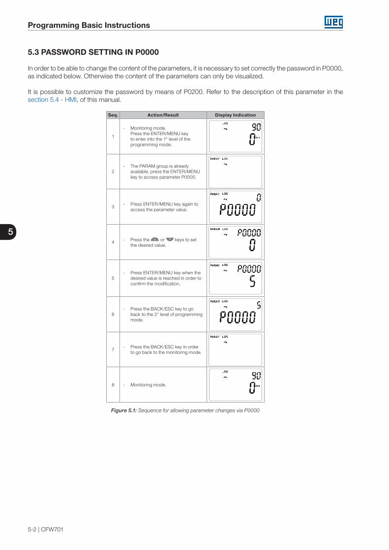
5
Programming Basic Instructions
5-2 | CFW701
5.3 PASSWORD SETTING IN P0000
In order to be able to change the content of the parameters, it is necessary to set correctly the password in P0000, as indicated below. Otherwise the content of the parameters can only be visualized.
It is possible to customize the password by means of P0200. Refer to the description of this parameter in the section 5.4 - HMI, of this manual.
Seq. Action/Result Display Indication
1
- Monitoring mode.Press the ENTER/MENU key to enter into the 1° level of the programming mode.
2 - The PARAM group is already
available, press the ENTER/MENU key to access parameter P0000.
3 - Press ENTER/MENU key again to
access the parameter value.
4 - Press the or keys to set the desired value.
5 - Press ENTER/MENU key when the
desired value is reached in order to confirm the modification.
6 - Press the BACK/ESC key to go
back to the 2° level of programming mode.
7 - Press the BACK/ESC key in order
to go back to the monitoring mode.
8 - Monitoring mode.
Figure 5.1: Sequence for allowing parameter changes via P0000

5
Programming Basic Instructions
CFW701 | 5-3
5.4 HMI
In the group “HMI” are the parameters related to the presentation of information on the keypad (HMI) display. See next the detailed description of the possible settings for those parameters.
P0200 – Password
Adjustable Range:
0 = Inactive1 = Active2 = Change Password
Factory Setting:
1
Properties:
Access groupsvia HMI:
HMI
Description:
It allows changing the password and/or setting its status, configuring it as active or inactive. For more details on each option, refer to the table 5.2 described next.
Table 5.2: Options for the parameter P0200
P0200 Kind of Action0 (Inactive) It allows parameter changes regardless of P0000.1 (Active) It does only allow parameter changes when the content of P0000 is equal to the password.
2 (Change Password) It makes the value presented in P0000 the current password.
Follow the procedure below to change your password:
1. Enter the current password value (factory settings, P0000 = 5).
2. Set the password parameter to inactive (P0200 = 0).
3. Enter the new desired password value in P0000.
4. Set the password parameter to change password (P0200 = 2).
5. The setting is completed, the new password is active and P0200 is automatically set to 1 (Enables password).
P0205 – Main Display Parameter Selection
P0206 – Secondary Display Parameter Selection
Adjustable Range:
0 to 1199 Factory Setting:
P0205=2P0206=1
Properties:
Access groupsvia HMI:
HMI
Description:
These parameters define which parameters are displayed on the keypad in the monitoring mode.
More details on the programming can be seen in section 5.6 - Display Indications in the Monitoring Mode Settings.
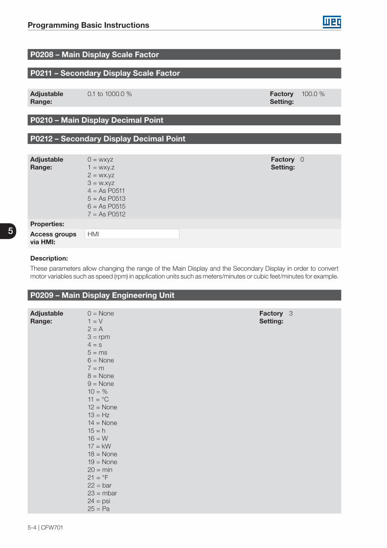
5
Programming Basic Instructions
5-4 | CFW701
P0208 – Main Display Scale Factor
P0211 – Secondary Display Scale Factor
Adjustable Range:
0.1 to 1000.0 % Factory Setting:
100.0 %
P0210 – Main Display Decimal Point
P0212 – Secondary Display Decimal Point
Adjustable Range:
0 = wxyz 1 = wxy.z2 = wx.yz3 = w.xyz4 = As P05115 = As P05136 = As P05157 = As P0512
Factory Setting:
0
Properties:
Access groupsvia HMI:
HMI
Description:
These parameters allow changing the range of the Main Display and the Secondary Display in order to convert motor variables such as speed (rpm) in application units such as meters/minutes or cubic feet/minutes for example.
P0209 – Main Display Engineering Unit
Adjustable Range:
0 = None 1 = V 2 = A 3 = rpm 4 = s 5 = ms 6 = None 7 = m 8 = None 9 = None 10 = % 11 = °C 12 = None 13 = Hz 14 = None 15 = h 16 = W 17 = kW 18 = None 19 = None 20 = min 21 = °F 22 = bar 23 = mbar 24 = psi 25 = Pa
Factory Setting:
3
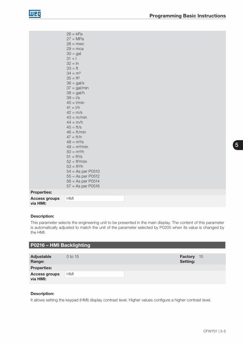
5
Programming Basic Instructions
CFW701 | 5-5
26 = kPa 27 = MPa 28 = mwc 29 = mca 30 = gal 31 = l 32 = in 33 = ft 34 = m³ 35 = ft³ 36 = gal/s 37 = gal/min 38 = gal/h 39 = l/s 40 = l/min 41 = l/h 42 = m/s 43 = m/min 44 = m/h 45 = ft/s 46 = ft/min 47 = ft/h 48 = m³/s 49 = m³/min 50 = m³/h 51 = ft³/s 52 = ft³/min 53 = ft³/h 54 = As per P0510 55 = As per P0512 56 = As per P0514 57 = As per P0516
Properties:
Access groupsvia HMI:
HMI
Description:
This parameter selects the engineering unit to be presented in the main display. The content of this parameter is automatically adjusted to match the unit of the parameter selected by P0205 when its value is changed by the HMI.
P0216 – HMI Backlighting
Adjustable Range:
0 to 15 Factory Setting:
15
Properties:
Access groupsvia HMI:
HMI
Description:
It allows setting the keypad (HMI) display contrast level. Higher values configure a higher contrast level.

5
Programming Basic Instructions
5-6 | CFW701
5.5 INDIRECT ENGINEERING UNITS
This parameter group allows the user to configure the indirect engineering units for SoftPLC user parameters.
P0510 – Indirect Engineering Unit 1
Adjustable Range:
0 = None1 = V2 = A3 = rpm4 = s5 = ms6 = None7 = m8 = None9 = None
10 = %11 = °C12 = None13 = Hz14 = None15 = h16 = W17 = kW18 = None19 = None20 = min21 = °F22 = bar23 = mbar24 = psi25 = Pa26 = kPa27 = MPa28 = mwc (meter of water column)29 = mca (metro de coluna d’agua)30 = gal31 = l (liter)32 = in33 = ft34 = m³35 = ft³36 = gal/s37 = gal/min (= GPM)38 = gal/h39 = l/s40 = l/min41 = l/h42 = m/s43 = m/min44 = m/h45 = ft/s46 = ft/min47 = ft/h48 = m³/s49 = m³/min50 = m³/h51 = ft³/s52 = ft³/min53 = ft³/h
Factory Setting:
22
Properties:
Access groupsvia HMI:
HMI

5
Programming Basic Instructions
CFW701 | 5-7
Description:
This parameter selects the engineering unit that will be displayed in SoftPLC user parameter that is associated whit it, i.e., any SoftPLC user parameter that has its engineering unit associated with an indirect engineering unit 1 will be displayed in this format in the CFW701 HMI.
NOTE!The parameters P1011, P1015, P1027, P1028, P1031 and P1033 of the main PID controller (HVAC functions) are associated with the indirect engineering unit 1.
P0511– Indirect Decimal Point 1
Adjustable Range:
0 = xywz 1 = xyw.z2 = xy.wz3 = x.ywz
Factory Setting:
1
Properties:
Access groupsvia HMI:
HMI
Description:
This parameter selects the decimal point that will be displayed in SoftPLC user parameter that is associated whit it, i.e., any SoftPLC user parameter that has its decimal point associated with an indirect decimal point 1 will be displayed in this format in the CFW701 HMI.
NOTE!The parameters P1011, P1015, P1027, P1028, P1031 and P1033 of the main PID controller (HVAC functions) are associated with the indirect decimal point 1.
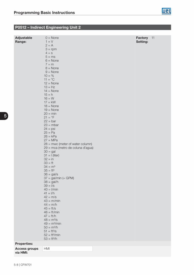
5
Programming Basic Instructions
5-8 | CFW701
P0512 – Indirect Engineering Unit 2
Adjustable Range:
0 = None 1 = V2 = A3 = rpm4 = s5 = ms6 = None7 = m8 = None9 = None
10 = %11 = °C12 = None13 = Hz14 = None15 = h16 = W17 = kW18 = None19 = None20 = min21 = °F22 = bar23 = mbar24 = psi25 = Pa26 = kPa27 = MPa28 = mwc (meter of water column)29 = mca (metro de coluna d’agua)30 = gal31 = l (liter)32 = in33 = ft34 = m³35 = ft³36 = gal/s37 = gal/min (= GPM)38 = gal/h39 = l/s40 = l/min41 = l/h42 = m/s43 = m/min44 = m/h45 = ft/s46 = ft/min47 = ft/h48 = m³/s49 = m³/min50 = m³/h51 = ft³/s52 = ft³/min53 = ft³/h
Factory Setting:
11
Properties:
Access groupsvia HMI:
HMI

5
Programming Basic Instructions
CFW701 | 5-9
Description:
This parameter selects the engineering unit that will be displayed in SoftPLC user parameter that is associated whit it, i.e., any SoftPLC user parameter that has its engineering unit associated with an indirect engineering unit 2 will be displayed in this format in the CFW701 HMI.
NOTE!The parameters P1060, P1062, P1073, P1074, P1076 and P1078 of the external PID controller 1 (HVAC functions) are associated with the indirect engineering unit 2.
P0513– Indirect Decimal Point 2
Adjustable Range:
0 = xywz 1 = xyw.z2 = xy.wz3 = x.ywz
Factory Setting:
1
Properties:
Access groupsvia HMI:
HMI
Description:
This parameter selects the decimal point that will be displayed in SoftPLC user parameter that is associated whit it, i.e., any SoftPLC user parameter that has its decimal point associated with an indirect decimal point 2 will be displayed in this format in the CFW701 HMI.
NOTE!The parameters P1060, P1062, P1073, P1074, P1076 and P1078 of the external PID controller 1 (HVAC functions) are associated with the indirect decimal point 2.
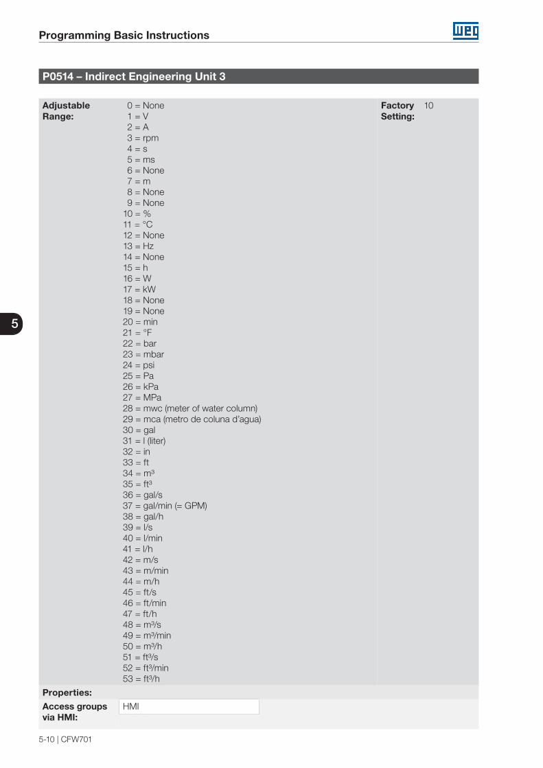
5
Programming Basic Instructions
5-10 | CFW701
P0514 – Indirect Engineering Unit 3
Adjustable Range:
0 = None 1 = V2 = A3 = rpm4 = s5 = ms6 = None7 = m8 = None9 = None
10 = %11 = °C12 = None13 = Hz14 = None15 = h16 = W17 = kW18 = None19 = None20 = min21 = °F22 = bar23 = mbar24 = psi25 = Pa26 = kPa27 = MPa28 = mwc (meter of water column)29 = mca (metro de coluna d’agua)30 = gal31 = l (liter)32 = in33 = ft34 = m³35 = ft³36 = gal/s37 = gal/min (= GPM)38 = gal/h39 = l/s40 = l/min41 = l/h42 = m/s43 = m/min44 = m/h45 = ft/s46 = ft/min47 = ft/h48 = m³/s49 = m³/min50 = m³/h51 = ft³/s52 = ft³/min53 = ft³/h
Factory Setting:
10
Properties:
Access groupsvia HMI:
HMI
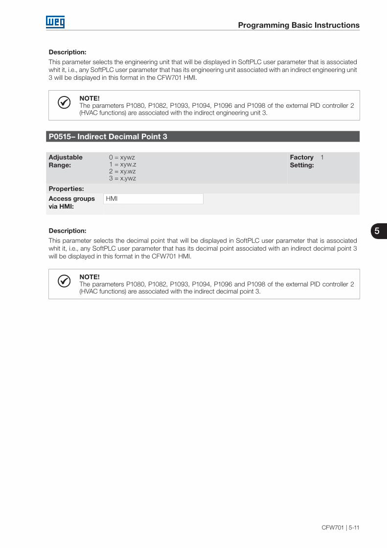
5
Programming Basic Instructions
CFW701 | 5-11
Description:
This parameter selects the engineering unit that will be displayed in SoftPLC user parameter that is associated whit it, i.e., any SoftPLC user parameter that has its engineering unit associated with an indirect engineering unit 3 will be displayed in this format in the CFW701 HMI.
NOTE!The parameters P1080, P1082, P1093, P1094, P1096 and P1098 of the external PID controller 2 (HVAC functions) are associated with the indirect engineering unit 3.
P0515– Indirect Decimal Point 3
Adjustable Range:
0 = xywz 1 = xyw.z2 = xy.wz3 = x.ywz
Factory Setting:
1
Properties:
Access groupsvia HMI:
HMI
Description:
This parameter selects the decimal point that will be displayed in SoftPLC user parameter that is associated whit it, i.e., any SoftPLC user parameter that has its decimal point associated with an indirect decimal point 3 will be displayed in this format in the CFW701 HMI.
NOTE!The parameters P1080, P1082, P1093, P1094, P1096 and P1098 of the external PID controller 2 (HVAC functions) are associated with the indirect decimal point 3.

5
Programming Basic Instructions
5-12 | CFW701
P0516 – Indirect Engineering Unit 4
Adjustable Range:
0 = None 1 = V2 = A3 = rpm4 = s5 = ms6 = None7 = m8 = None9 = None
10 = %11 = °C12 = None13 = Hz14 = None15 = h16 = W17 = kW18 = None19 = None20 = min21 = °F22 = bar23 = mbar24 = psi25 = Pa26 = kPa27 = MPa28 = mwc (meter of water column)29 = mca (metro de coluna d’agua)30 = gal31 = l (liter)32 = in33 = ft34 = m³35 = ft³36 = gal/s37 = gal/min (= GPM)38 = gal/h39 = l/s40 = l/min41 = l/h42 = m/s43 = m/min44 = m/h45 = ft/s46 = ft/min47 = ft/h48 = m³/s49 = m³/min50 = m³/h51 = ft³/s52 = ft³/min53 = ft³/h
Factory Setting:
13
Properties:
Access groupsvia HMI:
HMI

5
Programming Basic Instructions
CFW701 | 5-13
Description:
This parameter selects the engineering unit that will be displayed in SoftPLC user parameter that is associated whit it, i.e., any SoftPLC user parameter that has its engineering unit associated with an indirect engineering unit 4 will be displayed in this format in the CFW701 HMI.
NOTE!The parameters P1036, P1043 and P1047 are related to speed limits (Hz or rpm) on HVAC functions and are associated with the indirect engineering unit 4.
P0517– Indirect Decimal Point 4
Adjustable Range:
0 = xywz 1 = xyw.z2 = xy.wz3 = x.ywz
Factory Setting:
1
Properties:
Access groupsvia HMI:
HMI
Description:
This parameter selects the decimal point that will be displayed in SoftPLC user parameter that is associated whit it, i.e., any SoftPLC user parameter that has its decimal point associated with an indirect decimal point 4 will be displayed in this format in the CFW701 HMI.
NOTE!The parameters P1036, P1043 and P1047 are related to speed limits (Hz or rpm) on HVAC functions and are associated with the indirect decimal point 4.
5.6 DISPLAY INDICATIONS IN THE MONITORING MODE SETTINGS Every time the inverter is powered the display goes to the Monitoring Mode. To facilitate reading the parameters of the inverter, the display is designed to show two parameters at the same time according to the user's choice. These parameters (Main Display and Secondary Display) are shown in numerical form. The selection of these parameters is done via P0205 and P0206, as shown in figure 5.2.
Inverter status Secondary Display (selected by P0206).Displays the content of parameter (Pxxxx),Value of parameter (Pxxxx), Fault indication(Fxxx) or Alarm (Axxx)
Engineering Unit of the Main Display(selected by P0209)
Main Display (selected by P0205).Displays the content of parameter (Pxxxx),value of parameter (Pxxxx), Fault indication(Fxxx) or Alarm (Axxx)
MenuSelection of parameter groups
Figure 5.2: Screen at startup and display indication

5
Programming Basic Instructions
5-14 | CFW701
5.7 INCOMPATIBILITY BETWEEN PARAMETERS
If any of the combinations listed below occur, the CFW701 goes to the “Config” state.
1. Two or more DIx (P0263...P0270) programmed for (8 = FWD/REV).
2. Two or more DIx (P0263 .... P0270) programmed for (9 = LOC/REM).
3. Two or more DIx (P0263 .... P0270) programmed for (14 = Ramp 2).
4. Two or more DIx (P0263 .... P0270) programmed for (15 = Speed/Torque).
5. Two or more DIx (P0263 .... P0270) programmed for (24 = Disable Flying Start).
6. Two or more DIx (P0263 .... P0270) programmed for (25 = DC Link Regulator).
7. Two or more DIx (P0263 .... P0270) programmed for (26 = Programming Off).
8. Two or more DIx (P0263 .... P0270) programmed for (27 = Load User 1).
9. Two or more DIx (P0263 .... P0270) programmed for (28 = Load User 2).
10. Two or more DIx (P0263...P0270) programmed for (23 = Bypass mode)
11. Two or more DIx (P0263...P0270) programmed for (24 = Five mode)
12. Two or more DOx (P0275 ...P0279) programed for (39 = Drive Bypass Contactor)
13. Two or more DOx (P0275 ...P0279) programed for (40 = Mains Bypass Contactor)
14. [P0583≠0] and [P0029.bit9=1] (with Safety Stop) OR no DIx (P0263...P0270) programmed for (23 = Bypass mode) OR no DOx (P0275 ...P0279) programed for (39 = Drive Bypass Contactor) OR no DOx (P0275 ...P0279) programed for (40 = Mains Bypass Contactor)
15. [P0583=0] and OR any DIx (P0263...P0270) programmed for (23 = Bypass mode) OR any DOx (P0275 ...P0279) programed for (39 = Drive Bypass Contactor) OR any DOx (P0275 ...P0279) programed for (40 = Mains Bypass Contactor)
16. [P0580≠0] AND [P0029.bit9=1] (with Safety Stop)
17. [P0202 programmed for (0=V/f 60 Hz) OR (1=V/f 50 Hz) OR (2=Adjustable V/f) OR (3=VVW)] AND [P0231=1 (No Ramp Ref.) OR P0231=2 (Max.Torque Cur) OR P0236=1 (No Ramp Ref.) OR P0236=2 (Max.Torque Cur) OR P0241=1 (No Ramp Ref.) OR P0241=2 (Max.Torque Cur).
18. [P0202 programmed for (0=V/f 60 Hz) OR (1=V/f 50 Hz) OR (2=Adjustable V/f) OR (3=VVW)] AND [DIx (P0263...P0270) programmed for (10=JOG+) OR (11=JOG-).
19. [P0224 programmed for (1=DIx) OR P0227 programmed for (1=DIx)] AND [without DIx (P0263...P0270) programmed for (1=Run/Stop) AND without DIx (P0263...P0270) programmed for (2=General Enable) AND without DIx (P0263...P0270) programmed for (3=Fast Stop).
20. P0202 programed for 4 (Sensorless) and P0297 = 0 (1.25 kHz).
21. [31 ≤ P0295 ≤ 40] and [P0297 > 2].
22. [40 ≤ P0295 ≤ 46] and [P0297 ≠ 0 OR P0297 ≠ 4].
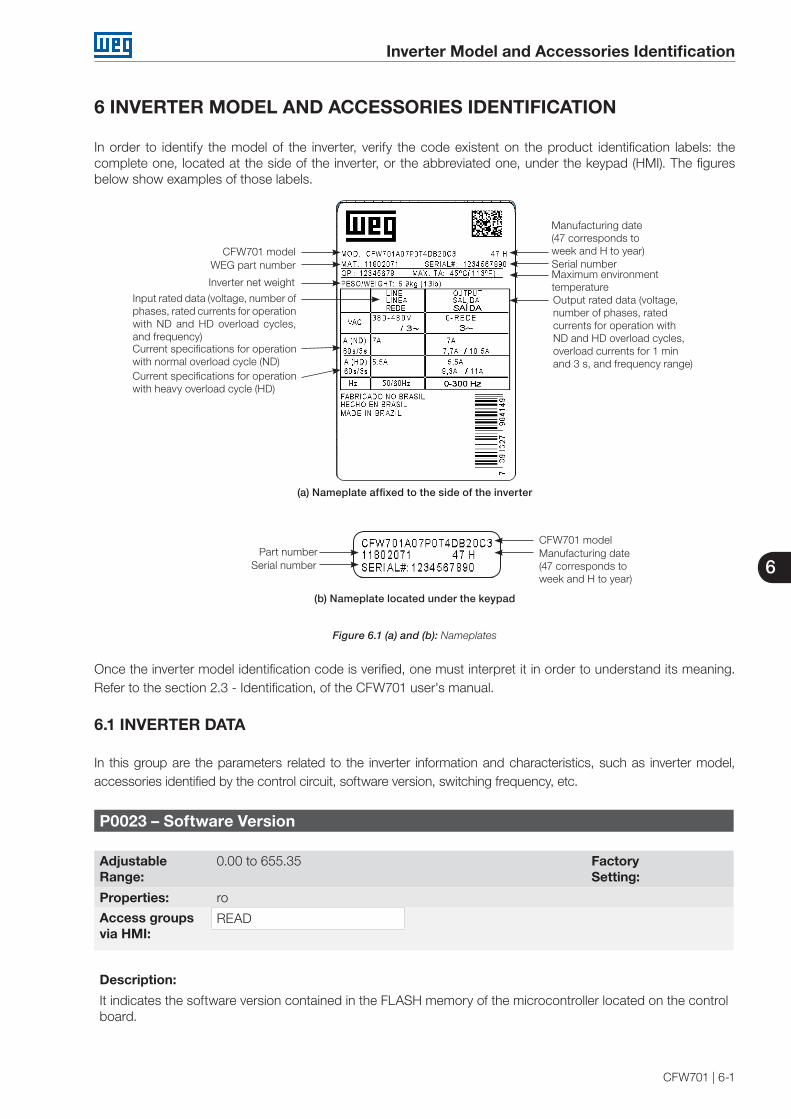
6
Inverter Model and Accessories Identification
CFW701 | 6-1
6 INVERTER MODEL AND ACCESSORIES IDENTIFICATION
In order to identify the model of the inverter, verify the code existent on the product identification labels: the complete one, located at the side of the inverter, or the abbreviated one, under the keypad (HMI). The figures below show examples of those labels.
CFW701 modelWEG part number
Manufacturing date (47 corresponds to week and H to year)
Inverter net weight
Input rated data (voltage, number of phases, rated currents for operation with ND and HD overload cycles, and frequency)
Output rated data (voltage, number of phases, rated currents for operation with ND and HD overload cycles, overload currents for 1 minand 3 s, and frequency range)
Maximum environment temperature
Serial number
Current specifications for operation with normal overload cycle (ND)Current specifications for operation with heavy overload cycle (HD)
(a) Nameplate affixed to the side of the inverter
CFW701 modelPart number Manufacturing date
(47 corresponds toweek and H to year)
Serial number
(b) Nameplate located under the keypad
Figure 6.1 (a) and (b): Nameplates
Once the inverter model identification code is verified, one must interpret it in order to understand its meaning. Refer to the section 2.3 - Identification, of the CFW701 user's manual.
6.1 INVERTER DATA
In this group are the parameters related to the inverter information and characteristics, such as inverter model, accessories identified by the control circuit, software version, switching frequency, etc.
P0023 – Software Version
Adjustable Range:
0.00 to 655.35 Factory Setting:
Properties: ro
Access groupsvia HMI:
READ
Description:
It indicates the software version contained in the FLASH memory of the microcontroller located on the control board.
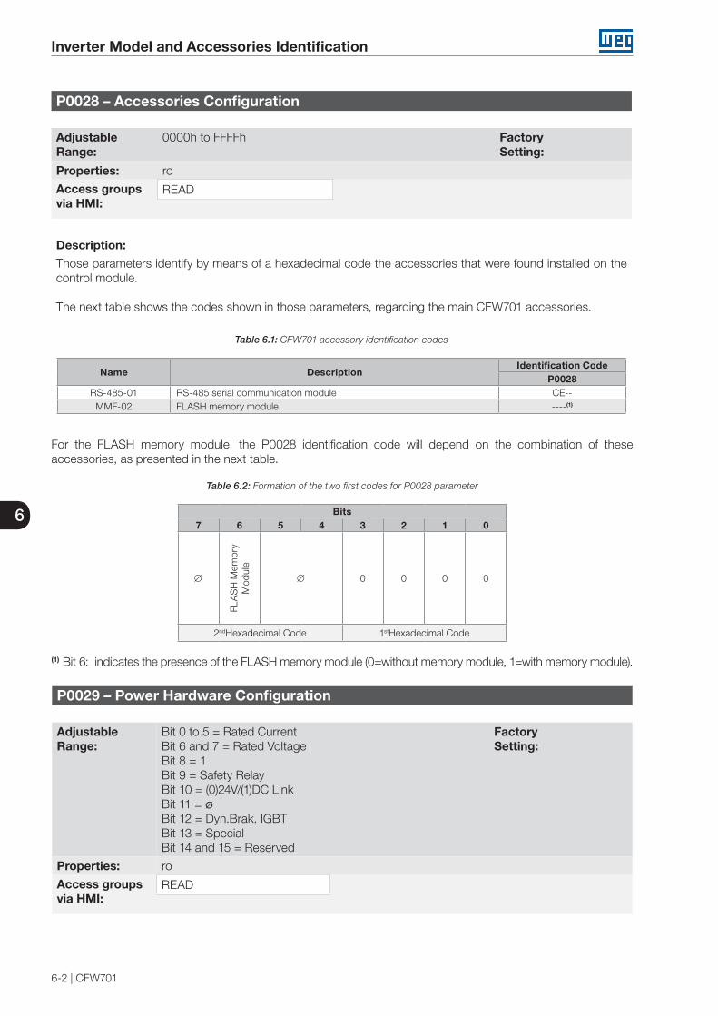
6
Inverter Model and Accessories Identification
6-2 | CFW701
P0028 – Accessories Configuration
Adjustable Range:
0000h to FFFFh Factory Setting:
Properties: ro
Access groupsvia HMI:
READ
Description:
Those parameters identify by means of a hexadecimal code the accessories that were found installed on the control module.
The next table shows the codes shown in those parameters, regarding the main CFW701 accessories.
Table 6.1: CFW701 accessory identification codes
Name DescriptionIdentification Code
P0028RS-485-01 RS-485 serial communication module CE--
MMF-02 FLASH memory module ----(1)
For the FLASH memory module, the P0028 identification code will depend on the combination of these accessories, as presented in the next table.
Table 6.2: Formation of the two first codes for P0028 parameter
Bits7 6 5 4 3 2 1 0
∅
FLA
SH
Mem
ory
Mod
ule
∅ 0 0 0 0
2ndHexadecimal Code 1stHexadecimal Code
(1) Bit 6: indicates the presence of the FLASH memory module (0=without memory module, 1=with memory module).
P0029 – Power Hardware Configuration
Adjustable Range:
Bit 0 to 5 = Rated Current Bit 6 and 7 = Rated Voltage Bit 8 = 1 Bit 9 = Safety Relay Bit 10 = (0)24V/(1)DC Link Bit 11 = ø Bit 12 = Dyn.Brak. IGBT Bit 13 = Special Bit 14 and 15 = Reserved
Factory Setting:
Properties: ro
Access groupsvia HMI:
READ

6
Inverter Model and Accessories Identification
CFW701 | 6-3
Description:
In a similar way than parameters P0028, the parameter P0029 identifies the inverter model and the present accessories.
The codification is formed by the combination of binary digits, and presented in the keypad (HMI) in hexadecimal format.
The bits that compose the code are explained in the next table.
Table 6.3: Parameter P0029 code constitution
Bits15 14 13 12 11 10 9 8 7 6 5 4 3 2 1 0
1 1 0
with
bra
king
IGB
T
0
with
24
V s
uppl
y
with
saf
ety
rela
y
1
Voltage00=200…240 V01=380…480 V10=500...600 V
Current
4th Hexadecimal Code 3rd Hexadecimal Code 2nd Hexadecimal Code 1st Hexadecimal Code
Bits 15, 14 and 13: are fixed in 110.
Bit 12: it indicates the presence of the dynamic braking IGBT (0 = with braking IGBT, 1 = without braking IGBT).
Bit 11: always 0.
Bit 10: indicates if the inverter has the DC/DC converter for receiving external 24 V electronics power supply (0=with DC/DC converter, 1=without DC/DC 24 V converter).
Bit 9: indicates the presence of the safety relay (0=without safety relay, 1=with safety relay).
Bit 8: indicates if the inverter is equipped with RFI suppressor filter (0=without RFI filter, 1=with RFI filter).
Bits 7 and 6: indicate the inverter power supply voltage (00=200...240 V, 01=380…480 V).
Bits 5, 4, 3, 2, 1 and 0: together with the voltage indication bits (7 and 6), they indicate the inverter rated current (ND). The next table presents the combinations available for those bits.
Table 6.4: Current codification for the parameter P0029
Size Voltage Current2nd
Hexadecimal Code
1st Hexadecimal
Code
A
200...240 V
2 A * 0 06 A * 0 17 A * 0 210 A * 0 3
7 A 0 410 A 0 513 A 0 616 A 0 7
B
24 A 0 828 A 0 9
33.5 A 0 A
C
45 A 0 C54 A 0 D70 A 0 E
D86 A 1 0105 A 1 1
E
180 A 1 2211 A 1 3142 A 1 4

6
Inverter Model and Accessories Identification
6-4 | CFW701
Size Voltage Current2nd
Hexadecimal Code
1st Hexadecimal
Code
A
380...480 V
3.6 A 4 05 A 4 17 A 4 210 A 4 4
13.5 A 4 5
B
17 A 4 824 A 4 631 A 4 7
C
38 A 4 345 A 4 A
58.5 A 4 B
D70.5 A 4 C88 A 4 D
E
105 A 5 0142 A 5 1180 A 5 2211 A 5 3
B
500...600 V
2.9 A 8 A4.2 A 8 B7 A 8 C10 A 8 D12 A 8 E17 A 8 F
D
22 A 8 627 A 8 732 A 8 844 A 8 9
E
53 A 9 063 A 9 180 A 9 2107 A 9 3125 A 9 4150 A 9 5
* Models with single-phase/three-phase power supply.
Example: For a 10 A, 380...480 V CFW701, with RFI suppressor filter, without safety relay and without external 24 V supply, the hexadecimal code presented in the keypad (HMI) for the parameter P0029 is C544 (refer to the table 6.5).
Table 6.5: Example of the code at P0029 for a specific inverter model
15 14 13 12 11 10 9 8 7 6 5 4 3 2 1 0
1 1 0 0 0 1 0 1 0 1 0 0 0 1 0 0
C 5 4 4
Table 6.4 (cont.): Current codification for the parameter P0029

6
Inverter Model and Accessories Identification
CFW701 | 6-5
P0295- ND/HD VFD Rated Current
Adjustable Range:
0 = 2 A / 2 A1 = 3.6 A /3.6 A2 = 5 A / 5 A3 = 6 A / 5 A4 = 7 A / 5.5 A5 = 7 A / 7 A6 = 10 A / 8 A7 = 10 A / 10 A8 = 13 A / 11 A9 = 13.5 A / 11 A
10 = 16 A / 13 A11 = 17 A / 13.5 A12 = 24 A / 19 A13 = 24 A / 20 A14 = 28 A / 24 A15 = 31 A / 25 A16 = 33.5 A / 28 A17 = 38 A / 33 A18 = 45 A / 36 A19 = 45 A / 38 A20 = 54 A / 45 A21 = 58.5 A / 47 A22 = 70 A / 56 A23 = 70.5 A / 61 A24 = 86 A / 70 A25 = 88 A / 73 A26 = 105 A / 86 A27 = 105 A / 88 A28 = 142 A / 115 A29 = 180 A / 142 A30 = 211 A / 180 A31 = 2.9 A / 2.7 A32 = 4.2 A / 3.8 A33 = 7 A / 6.5 A34 = 10 A / 9 A35 = 12 A / 10 A36 = 17 A / 17 A37 = 22 A / 19 A38 = 27 A / 22 A39 = 32 A / 27 A40 = 44 A / 36 A41 = 53 A / 44 A42 = 63 A / 53 A43 = 79 A / 66 A44 = 107 A / 90 A45 = 125 A / 107 A46 = 150 A / 122 A
Factory Setting:
Properties: ro
Access groupsvia HMI:
READ
Description:
This parameter presents the inverter rated current for the normal overload regimen (ND) and for the heavy overload regimen (HD). The inverter operation mode, if it is ND or HD, is defined by the content of P0298.

6
Inverter Model and Accessories Identification
6-6 | CFW701
P0296 – Line Rated Voltage
Adjustable Range:
0 = 200 - 240 V1 = 380 V2 = 400 - 415 V3 = 440 - 460 V4 = 480 V5 = 500 - 525 V6 = 550 - 575 V7 = 600 V
Factory Setting:
According to the inverter model
Properties: cfg
Access groupsvia HMI:
Description:
Setting according to the inverter power supply voltage.
The adjustable range depends on the inverter model, according to the table 6.6, which also presents the factory default value.
NOTE!When adjusted via the keypad (HMI), this parameter may change automatically the following parameters: P0151, P0153, P0185, P0321, P0322 and P0323.
Table 6.6: P0296 setting according to the CFW701 inverter model
Inverter Model Adjustable Range Factory Setting200-240 V 0 = 200 ... 240 V 0
380-480 V
1 = 380 V2 = 400 / 415 V3 = 440 / 460 V4 = 480 V
3
500-600V5 = 500-525 V6 = 550-575 V7 = 600 V
6

6
Inverter Model and Accessories Identification
CFW701 | 6-7
P0297 – Switching Frequency
Adjustable Range:
0 = 1.25 kHz 1 = 2.5 kHz2 = 5.0 kHz3 = 10.0 kHz4 = 2.0 kHz
Factory Setting:
2
Properties: cfg
Access groupsvia HMI:
Description:
Refer to the allowed current for switching frequencies different from the default, in the tables available in chapter 8 - Technical Specifications, of the CFW701 user's manual.
The inverter switching frequency can be adjusted according to the needs of the application. Higher switching frequencies imply in lower motor acoustic noise, however, the selection of the switching frequency results in a compromise between the motor acoustic noises, the losses in the inverter IGBTs and the maximum allowed currents.
The reduction of the switching frequency reduces effects related to motor instability, which occur in specific application conditions. It also reduces the earth leakage current, being able to avoid the actuation of the faults F074 (Ground Fault) or F070 (Output Overcurrent/Short-circuit).
Note: The option 0 (1.25 kHz) is only allowed for the V/f or VVW control (P0202=0, 1, 2 or 3).
P0298 - Application
Adjustable Range:
0 = Normal Duty (ND)1 = Heavy Duty (HD)
Factory Setting:
0
Properties: cfg
Access groupsvia HMI:
Description:
Set the content of this parameter according to the application.
The Normal Duty Regimen (ND) defines the maximum current for continuous operation (Inom-ND) and an overload of 110 % during 1 minute. It must be used for driving motors that are not subject in that application to high torques in relation to their rated torque, when operating in permanent regimen, during start, acceleration or deceleration.
The Heavy Duty Regimen (HD) defines the maximum current for continuous operation (Inom-HD) and an overload of 150 % during 1 minute. It must be used for driving motors that are subject in that application to high overload torques in relation to their rated torque, when operating in constant speed, during start, acceleration or deceleration.
The Inom-ND and Inom-HD are presented in P0295. Refer to the CFW701 user's manual chapter 8 - Technical Specifications, for more details regarding these operation regimens.

6
Inverter Model and Accessories Identification
6-8 | CFW701
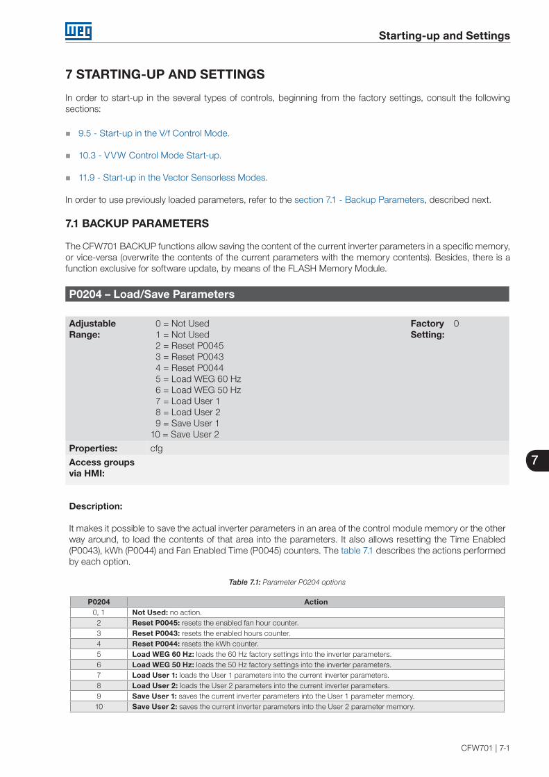
7
Starting-up and Settings
CFW701 | 7-1
7 STARTING-UP AND SETTINGS
In order to start-up in the several types of controls, beginning from the factory settings, consult the following sections:
9.5 - Start-up in the V/f Control Mode.
10.3 - VVW Control Mode Start-up.
11.9 - Start-up in the Vector Sensorless Modes.
In order to use previously loaded parameters, refer to the section 7.1 - Backup Parameters, described next.
7.1 BACKUP PARAMETERS
The CFW701 BACKUP functions allow saving the content of the current inverter parameters in a specific memory, or vice-versa (overwrite the contents of the current parameters with the memory contents). Besides, there is a function exclusive for software update, by means of the FLASH Memory Module.
P0204 – Load/Save Parameters
Adjustable Range:
0 = Not Used1 = Not Used2 = Reset P00453 = Reset P00434 = Reset P00445 = Load WEG 60 Hz6 = Load WEG 50 Hz7 = Load User 18 = Load User 29 = Save User 1
10 = Save User 2
Factory Setting:
0
Properties: cfg
Access groupsvia HMI:
Description:
It makes it possible to save the actual inverter parameters in an area of the control module memory or the other way around, to load the contents of that area into the parameters. It also allows resetting the Time Enabled (P0043), kWh (P0044) and Fan Enabled Time (P0045) counters. The table 7.1 describes the actions performed by each option.
Table 7.1: Parameter P0204 options
P0204 Action0, 1 Not Used: no action.2 Reset P0045: resets the enabled fan hour counter.3 Reset P0043: resets the enabled hours counter.4 Reset P0044: resets the kWh counter.5 Load WEG 60 Hz: loads the 60 Hz factory settings into the inverter parameters.6 Load WEG 50 Hz: loads the 50 Hz factory settings into the inverter parameters.7 Load User 1: loads the User 1 parameters into the current inverter parameters.8 Load User 2: loads the User 2 parameters into the current inverter parameters.9 Save User 1: saves the current inverter parameters into the User 1 parameter memory.10 Save User 2: saves the current inverter parameters into the User 2 parameter memory.

7
Starting-up and Settings
7-2 | CFW701
User Memory 1
User Memory 2
Factory Setting
Current inverter
parameters
P0204=09
P0204=7
P0204=10P0204=8
P0204=5 ou 6
Figure 7.1: Parameter transfer
In order to load parameters from user 1 and/or User 2 to the CFW701 operation area (P0204=7 or 8), it is necessary that these areas had been saved previously.
The operation of loading one of those memories can also be performed via digital inputs (DIx). Refer to item 13.1.3 - Digital Inputs, for more details regarding this programming (P0204=9 or 10).
NOTE!When P0204=5 or 6, the parameters P0296 (Rated voltage), P0297 (Switching frequency), P0308 (Serial address) are not changed by the factory settings.
P0317 – Oriented Start-up
Adjustable Range:
0 = No1 = Yes
Factory Setting:
0
Properties: cfg
Access groupsvia HMI:
STARTUP
Description:
When this parameter is changed to “1”, the Oriented Start-up routine starts. The CFW701 goes into the “CONF” state, which is indicated on the HMI. Within the Oriented Start-up, the user has access to the important configuration parameters of the CFW701 and of the motor for the control type to be used in the application. For further information on the use of this parameter, refer to the following sections:
10.3 - VVW Control Mode Start-up. 11.9 - Start-up in the Vector Modes Sensorless.

7
Starting-up and Settings
CFW701 | 7-3
P0318 – Copy Function MMF
Adjustable Range:
0 = Off1 = VFD → MMF2 = MMF → VFD3 = VFD Synchronization → MMF4 = MMF Format 5 = SoftPLC Program Copy
Factory Setting:
0
Properties: cfg
Access groupsvia HMI:
Description:
This function allows saving the contents of the inverter writing parameters in the FLASH Memory Module (MMF), or vice-versa, and can be used to transfer the contents of the parameters from one inverter to another.
Table 7.2: Parameter P0318 options
P0318 Action0 Inactive: no action.1 Inverter → MMF: transfers the inverter current parameters contents to the MMF.2 MMF → Inverter: transfers the contents of the parameters stored in the MMF to the inverter control board. 3 Updates the MMF automatically whenever any parameter of the CFW701 is changed.4 Format the MMF.5 Copy the SoftPLC program from the MMF to the CFW701.
After storing the parameters of one inverter in a FLASH memory module, it is possible to pass them to another inverter with this function.
NOTE!During the inverter operation, the modified parameters are saved in the FLASH memory module regardless of user's command, when P0318 = 3. This assures that the MMF will always have an updated copy of the inverter parameters.
NOTE!When the inverter is powered on and the memory module is present, the current values of its parameters is overridden if P0318 = 3. If you want to copy from another inverter, set P0318 to 0 before inserting the card.
NOTE!When the inverter is powered on and the memory module is not detected, P0318 is not visible or changeable by the user and it is automatically set to 0.

7
Starting-up and Settings
7-4 | CFW701

8
Available Control Types
CFW701| 8-1
8 AVAILABLE CONTROL TYPES
The inverter feeds the motor with variable voltage, current and frequency, by means of whose the control of the motor speed is obtained. The values applied to the motor follow a control strategy, which depends on the selected type of control and on the inverter parameter settings.
Choose the control type in function of the static and dynamic, torque and speed requirements of the driven load.
Control modes and their main characteristics:
V/f: scalar control; it is the simplest control mode, by imposed voltage/frequency; with an open loop speed regulation or with slip compensation (programmable); it allows multimotor operation.
VVW: Voltage Vector WEG; it allows a static speed control more accurate than the V/f mode; it adjusts itself automatically to the line variations, and also to the load variations, however it does not present fast dynamic response.
Sensorless Vector: it is a field oriented control; without motor speed sensor; able to drive any standard motor; speed control range of 1:100; speed control static precision of 0.5 % of the rated speed; high control dynamics.
All these control modes are described in details in the chapters 9 - Scalar Control (V/f), 10 - VVW Control and 11 - Vector Control, the related parameters and orientations regarding the use of each of these modes.

8
Available Control Types
8-2 | CFW701
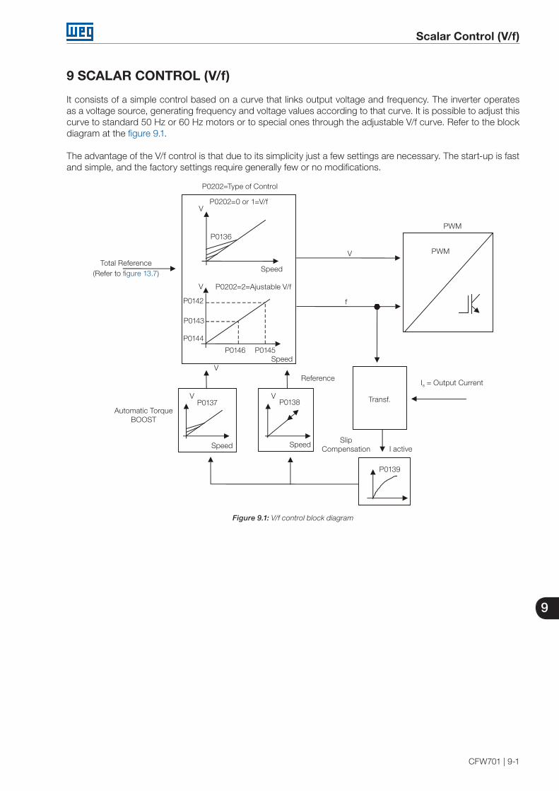
9
Scalar Control (V/f)
CFW701 | 9-1
9 SCALAR CONTROL (V/f)
It consists of a simple control based on a curve that links output voltage and frequency. The inverter operates as a voltage source, generating frequency and voltage values according to that curve. It is possible to adjust this curve to standard 50 Hz or 60 Hz motors or to special ones through the adjustable V/f curve. Refer to the block diagram at the figure 9.1.
The advantage of the V/f control is that due to its simplicity just a few settings are necessary. The start-up is fast and simple, and the factory settings require generally few or no modifications.
V
V
Reference
PWM
PWM
Speed
P0202=2=Ajustable V/f
P0202=Type of Control
Total Reference(Refer to figure 13.7)
Is = Output Current
Transf.
I active
P0139
V
f
P0202=0 or 1=V/f
P0142
P0143
P0144
P0138P0137
Speed Speed
SpeedP0146 P0145
Automatic Torque BOOST
Slip Compensation
VV
V
P0136
Figure 9.1: V/f control block diagram
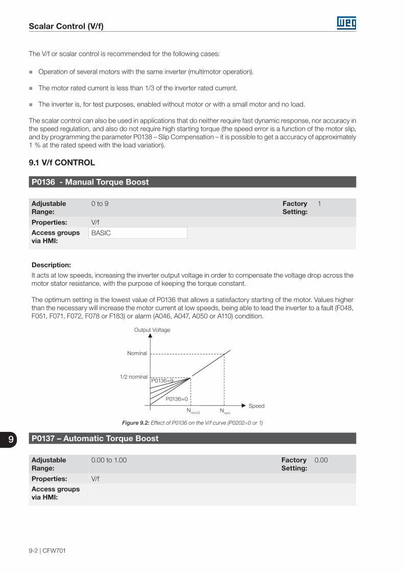
9
Scalar Control (V/f)
9-2 | CFW701
The V/f or scalar control is recommended for the following cases:
Operation of several motors with the same inverter (multimotor operation).
The motor rated current is less than 1/3 of the inverter rated current.
The inverter is, for test purposes, enabled without motor or with a small motor and no load.
The scalar control can also be used in applications that do neither require fast dynamic response, nor accuracy in the speed regulation, and also do not require high starting torque (the speed error is a function of the motor slip, and by programming the parameter P0138 – Slip Compensation – it is possible to get a accuracy of approximately 1 % at the rated speed with the load variation).
9.1 V/f CONTROL
P0136 - Manual Torque Boost
Adjustable Range:
0 to 9 Factory Setting:
1
Properties: V/f
Access groups via HMI:
BASIC
Description:
It acts at low speeds, increasing the inverter output voltage in order to compensate the voltage drop across the motor stator resistance, with the purpose of keeping the torque constant.
The optimum setting is the lowest value of P0136 that allows a satisfactory starting of the motor. Values higher than the necessary will increase the motor current at low speeds, being able to lead the inverter to a fault (F048, F051, F071, F072, F078 or F183) or alarm (A046, A047, A050 or A110) condition.
Output Voltage
Nominal
1/2 nominal
SpeedNnom/2 Nnom
P0136=9
P0136=0
Figure 9.2: Effect of P0136 on the V/f curve (P0202=0 or 1)
P0137 – Automatic Torque Boost
Adjustable Range:
0.00 to 1.00 Factory Setting:
0.00
Properties: V/f
Access groupsvia HMI:

9
Scalar Control (V/f)
CFW701 | 9-3
Description:The Automatic Torque Boost compensates the voltage drop on the stator resistance in function of the motor active current.
The criteria for adjusting P0137 are the same as for the parameter P0136.
P0136 I x R
P0137Automatic
I x R
Voltage Applied tothe Motor
P0007
P0139
Active Output Current
Speed Reference
Figure 9.3: Torque Boost block diagram
Output Voltage
Nominal
1/2 Nominal
Compensation Zone
Nnom/2 Nnom
Speed
Figure 9.4: Effect of P0137 on the V/f curve (P0202=0…2)
P0138 – Slip Compensation
Adjustable Range:
-10.0 to +10.0 % Factory Setting:
0.0 %
Properties: V/f
Access groupsvia HMI:
Description:
The parameter P0138 is used in the motor slip compensation function, when adjusted to positive values. In this case it compensates the drop in the speed due to the application of load to the motor shaft. It increases the output frequency in function of the increase in the motor active current.
The setting of P0138 allows regulating the slip compensation precisely. Once P0138 is adjusted the inverter will keep the speed constant even with load variations by adjusting the voltage and frequency automatically.
Negative values are used in special applications where one wants to reduce the output speed in function of the increase in the motor current.
E.g.: Load distribution in motors operated in parallel.
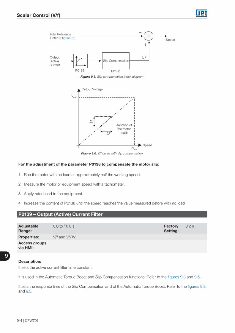
9
Scalar Control (V/f)
9-4 | CFW701
Speed
Total Reference (Refer to figure 9.1)
Slip Compensation ∆ FOutput
Active Current
P0139 P0138
Figure 9.5: Slip compensation block diagram
Output Voltage
(function of the motor
load)
SpeedNnom
Vnom
∆V
∆F
Figure 9.6: V/f curve with slip compensation
For the adjustment of the parameter P0138 to compensate the motor slip:
1. Run the motor with no load at approximately half the working speed.
2. Measure the motor or equipment speed with a tachometer.
3. Apply rated load to the equipment.
4. Increase the content of P0138 until the speed reaches the value measured before with no load.
P0139 – Output (Active) Current Filter
Adjustable Range:
0.0 to 16.0 s Factory Setting:
0.2 s
Properties: V/f and VVW
Access groupsvia HMI:
Description:
It sets the active current filter time constant.
It is used in the Automatic Torque Boost and Slip Compensation functions. Refer to the figures 9.3 and 9.5.
It sets the response time of the Slip Compensation and of the Automatic Torque Boost. Refer to the figures 9.3 and 9.5.

9
Scalar Control (V/f)
CFW701 | 9-5
P0202 – Control Type
Adjustable Range:
0=V/f 60 Hz1=V/f 50 Hz2=V/f Adjustable3=VVW (Voltage Vector WEG)4=Sensorless
Factory Setting:
0
Properties: cfg
Access groupsvia HMI:
Description:
In order to get an overview of the control types, as well as orientation to choose the most suitable type for the application, refer to the chapter 8 - Available Control Types.
For the V/f mode, select P0202=0, 1 or 2:
Parameter P0202 setting for the V/f mode:
P0202=0 for motors with rated frequency=60 Hz. P0202=1 for motors with rated frequency=50 Hz.
Notes:
The correct setting of P0400 assures the application of the correct V/f ratio at the output, in case of 50 Hz or 60 Hz motors with voltage different from the inverter input voltage.
P0202=2: for special motors with rated frequency different from 50 Hz or 60 Hz, or for the adjustment of special V/f curve profiles. Example: the approximation of a quadratic V/f curve for energy saving in variable torque loads like centrifuge pumps and fans.
9.2 ADJUSTABLE V/f CURVE
P0142 – Maximum Output Voltage
P0143 – Intermediate Output Voltage
P0144 – 3 Hz Output Voltage
Adjustable Range:
0.0 to 100.0 % Factory Setting:
P0142 = 100.0 %P0143 = 50.0 %P0144 = 8.0 %

9
Scalar Control (V/f)
9-6 | CFW701
P0145 – Field Weakening Speed
P0146 – Intermediate Speed
Adjustable Range:
0 to 18000 rpm Factory Setting:
P0145 = 1800 rpmP0146 = 900 rpm
Properties: Adj and cfg
Access groupsvia HMI:
Description:
This function allows the adjustment of the curve that links output voltage and frequency by means of parameters, as presented by the figure 9.7, in V/f mode.
It is necessary when the used motor has a rated frequency different from 50 Hz or 60 Hz, or when a quadratic V/f curve, for energy saving in the operation of centrifuge pumps and fans, is desired, or even in special applications, such as, for instance, when a transformer is used at the inverter output, between it and the motor.
The function is activated with P0202=2 (Adjustable V/f).
The factory setting of P0144 (8.0 %) is adequate for standard motors with rated frequency of 60 Hz. When using a motor with rated frequency (adjusted in P0403) different from 60 Hz, the default value for P0144 may become inadequate, being able to cause difficulties in the motor starting. A good approximation for the setting of P0144 is given by the formula:
P0144 = 3 x P0142
P0403
If it is necessary to increase the starting torque, increase gradually the value of P0144.
Output Voltage
Line rated voltage100 %
P0142
P0143
P0144
0.1Hz 3Hz P0146 P0145 P0134
P0202=2
Speed/Frequency
Figure 9.7: V/f curve in function of P0142 to P0146

9
Scalar Control (V/f)
CFW701 | 9-7
9.3 V/f CURRENT LIMITATION
P0135 – Maximum Output Current
Adjustable Range:
0.2 to 2xInom-HD Factory Setting:
1.5xInom-HD
Properties: V/f and VVW
Access groupsvia HMI:
BASIC
P0344 – Current Limitation Configuration
Adjustable Range:
0=Hold - FL ON1=Decel. - FL ON2=Hold - FL OFF3=Decel. - FL OFF
Factory Setting:
1
Properties: V/f, cfg and VVW
Access groupsvia HMI:
Description:
It is the current limitation for the V/f control with actuation mode defined by P0344 (refer to the table 9.1) and the current limit defined by P0135.
Table 9.1: Current limitation configuration
P0344 Function Description
0 = Hold - FL ONCurrent limitation of the “Ramp Hold” type.Active fast current limitation.
Current limitation according to the figure 9.8 (a).Fast current limitation at the value 1.9xInom-HD active.
1 = Decel. - FL ONCurrent limitation of the “Ramp Deceleration” type.Active fast current limitation.
Current limitation according to the figure 9.8 (b).Fast current limitation at the value 1.9 xInom-HD active.
2 = Hold - FL OFFCurrent limitation of the “Ramp Hold” type.Inactive fast current limitation.
Current limitation according to the figure 9.8 (a).
3 = Decel. - FL OFFCurrent limitation of the “Ramp Deceleration” type.Inactive fast current limitation.
Current limitation according to the figure 9.8 (b).
Current limitation of the “Ramp Hold” type:
It avoids the stalling of the motor during a torque overload at the acceleration or at the deceleration.
Working: if the motor current exceeds the value adjusted in P0135 during the acceleration or the deceleration, the speed will no longer be increased (acceleration) or decreased (deceleration). When the motor current reaches a value below P0135 the motor will again accelerate or decelerate. Refer to the figure 9.8 (a).
It acts faster than the “Ramp Deceleration” mode.
It acts in the motorization and braking modes.
Current limitation of the “Ramp Deceleration” type:
It avoids the stalling of the motor during a torque overload at the acceleration or at constant speed.
Working: if the motor current exceeds the value adjusted in P0135, the input of the speed ramp is set to zero forcing a deceleration. When the motor current reaches a value below P0135 the motor will accelerate again. Refer to the figure 9.8 (b).
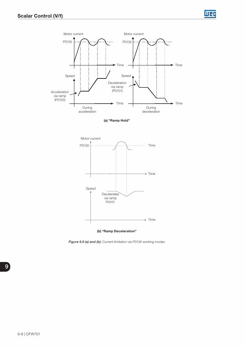
9
Scalar Control (V/f)
9-8 | CFW701
Motor current
P0135P0135
SpeedSpeed
Accelerationvia ramp(P0100)
Decelerationvia ramp(P0101)
Duringacceleration
Duringdeceleration
Time
Time
Time
Time
Motor current
(a) “Ramp Hold”
Motor current
P0135 Time
Time
Time
Deceleratesvia rampP0101
Speed
(b) “Ramp Deceleration”
Figure 9.8 (a) and (b): Current limitation via P0135 working modes

9
Scalar Control (V/f)
CFW701 | 9-9
9.4 V/f DC VOLTAGE LIMITATION
There are two functions in the inverter for limiting the DC link voltage during the motor braking. They act limiting the braking torque and power, avoiding therefore the tripping of the inverter by overvoltage (F022).
The overvoltage on the DC link is more common when a load with high inertia is driven or when a short deceleration time is programmed.
NOTE!When using the dynamic braking the function “Ramp Hold” or “Ramp Acceleration” must be disabled. Refer to the P0151 description.
In the V/f mode, there are two types of function to limit the DC link voltage:
1 - “Ramp Hold”:
It is effective only during the deceleration.
Working: When the DC link voltage reaches the level adjusted in P0151, a command is sent to the “ramp” block, which inhibits the motor speed variation (“ramp hold”). Refer to the figures 9.9 and 9.10.
With this function an optimized deceleration time (minimum possible) for the driven load is obtained.
The use is recommended for loads running with high inertia moment referenced to the motor shaft, or loads with medium inertia, which require short deceleration ramps.
Error < 0: Ramp Hold = inactive
Error ≥ 0: Ramp Hold = active
Ramp Hold
Output
Acceleration/Deceleration Ramp
Dc linkVoltage (Ud)
Error
Input
P0151
Figure 9.9: Limitation of the DC link voltage using Ramp Acceleration function block diagram
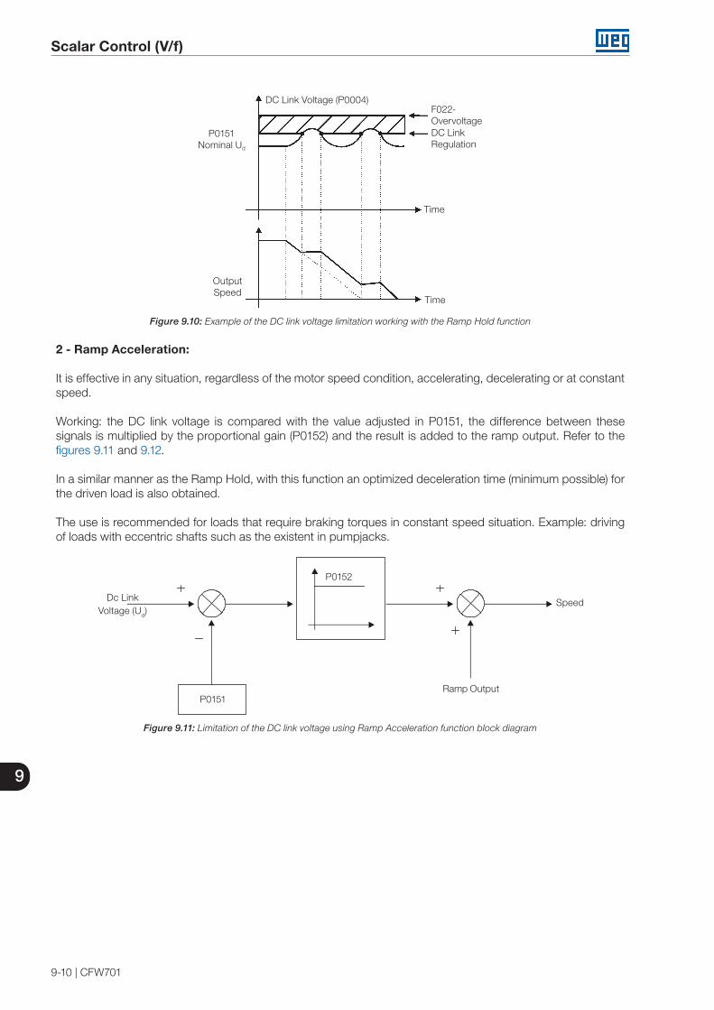
9
Scalar Control (V/f)
9-10 | CFW701
DC Link Voltage (P0004)F022-Overvoltage
Time
DC Link Regulation
Output Speed
Time
P0151Nominal Ud
Figure 9.10: Example of the DC link voltage limitation working with the Ramp Hold function
2 - Ramp Acceleration:
It is effective in any situation, regardless of the motor speed condition, accelerating, decelerating or at constant speed.
Working: the DC link voltage is compared with the value adjusted in P0151, the difference between these signals is multiplied by the proportional gain (P0152) and the result is added to the ramp output. Refer to the figures 9.11 and 9.12.
In a similar manner as the Ramp Hold, with this function an optimized deceleration time (minimum possible) for the driven load is also obtained.
The use is recommended for loads that require braking torques in constant speed situation. Example: driving of loads with eccentric shafts such as the existent in pumpjacks.
Dc LinkVoltage (Ud)
P0152
P0151
Speed
Ramp Output
Figure 9.11: Limitation of the DC link voltage using Ramp Acceleration function block diagram
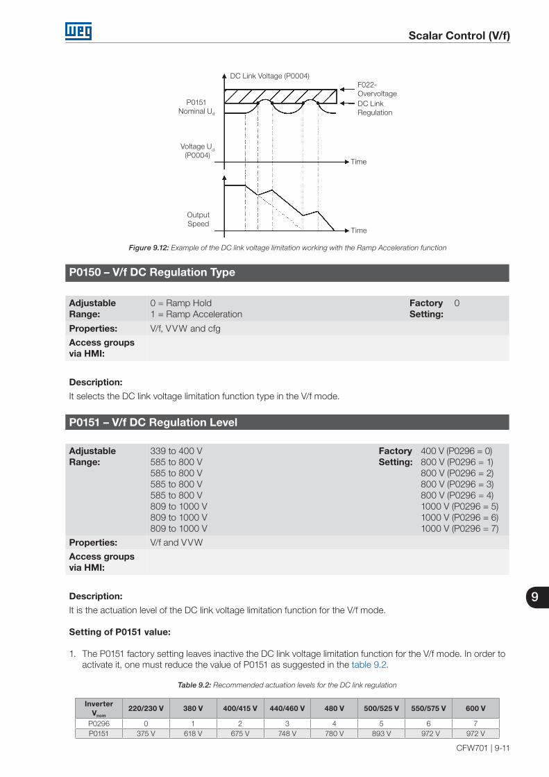
9
Scalar Control (V/f)
CFW701 | 9-11
DC Link Voltage (P0004)F022-Overvoltage
Time
DC Link Regulation
Output Speed
Time
P0151Nominal Ud
Voltage Ud
(P0004)
Figure 9.12: Example of the DC link voltage limitation working with the Ramp Acceleration function
P0150 – V/f DC Regulation Type
Adjustable Range:
0 = Ramp Hold1 = Ramp Acceleration
Factory Setting:
0
Properties: V/f, VVW and cfg
Access groupsvia HMI:
Description:
It selects the DC link voltage limitation function type in the V/f mode.
P0151 – V/f DC Regulation Level
Adjustable Range:
339 to 400 V 585 to 800 V 585 to 800 V585 to 800 V585 to 800 V809 to 1000 V809 to 1000 V809 to 1000 V
Factory Setting:
400 V (P0296 = 0)800 V (P0296 = 1)800 V (P0296 = 2)800 V (P0296 = 3)800 V (P0296 = 4)1000 V (P0296 = 5)1000 V (P0296 = 6)1000 V (P0296 = 7)
Properties: V/f and VVW
Access groupsvia HMI:
Description:
It is the actuation level of the DC link voltage limitation function for the V/f mode.
Setting of P0151 value:
1. The P0151 factory setting leaves inactive the DC link voltage limitation function for the V/f mode. In order to activate it, one must reduce the value of P0151 as suggested in the table 9.2.
Table 9.2: Recommended actuation levels for the DC link regulation
InverterVnom
220/230 V 380 V 400/415 V 440/460 V 480 V 500/525 V 550/575 V 600 V
P0296 0 1 2 3 4 5 6 7P0151 375 V 618 V 675 V 748 V 780 V 893 V 972 V 972 V
9
Scalar Control (V/f)
9-12 | CFW701
2. In case DC link overvoltage (F022) keeps happening during the deceleration, reduce the value of P0151 gradually or increase the deceleration ramp time (P0101 and/or P0103).
3. If the supply line is permanently at a voltage level that results in a DC link voltage higher than the P0151 setting, it will not be possible to decelerate the motor. In this case, reduce the line voltage or increase the value of the P0151 setting.
4. If, even with the procedures above, it is not possible to decelerate the motor in the necessary time, use the dynamic braking (Refer to the chapter 14 - Dynamic Braking).
P0152 – V/f DC Regulation Proportional Gain
Adjustable Range:
0.00 to 9.99 Factory Setting:
1.50
Properties: V/f and VVW
Access groupsvia HMI:
Description:
It defines the DC Link Voltage Regulator proportional gain (refer to the figure 9.11).
P0152 multiplies the DC link voltage error, i.e., Error = actual DC link voltage – (P0151), and it is normally used to prevent overvoltage in applications with eccentric loads.
9.5 START-UP IN THE V/f CONTROL MODE
NOTE!Read the whole CFW701 user's manual before installing, powering or operating the inverter.
Sequence for installation, verification, powering and start-up:
1. Install the inverter: according to the chapter 3 - Installation and Connection, of the CFW700 user's manual, wiring all the power and control connections.
2. Prepare the inverter and apply power: according to the section 5.1 - Prepare for Start-Up, of the CFW701 user's manual.
3. Adjust the password P0000=5: according to the section 5.3 - Password Setting in P0000, of this manual.
4. Adjust the inverter to operate with the application line and motor: execute the Oriented Start-up routine according to item 5.2.1 - Oriented Start-up Menu, of the CFW701 user's manual. Refer to the section 11.7 - Motor Data, of this manual.
5. Setting of specific parameters and functions for the application: program the digital and analog inputs and outputs, HMI keys, etc., according to the application needs.
For applications:
That are simple, which can use the factory settings programming for the digital and analog inputs and outputs, use the Menu “BASIC”. Refer to item 5.2.2 - Basic Application Menu, of the CFW701 user's manual.
That require only the digital and analog inputs and outputs with programming different from the factory settings, use the Menu “I/O”.
That need functions as Flying Start, Ride-Through, DC Braking, Dynamic Braking, etc., access and modify those functions parameters by means of the Menu “PARAM”.
10
VVW Control
CFW701 | 10-1
10 VVW CONTROL
The VVW (Voltage Vector WEG) control mode uses a control method with intermediate performance between V/f and Sensorless Vector. Refer to the figure 10.1 block diagram.
The main advantage compared to the V/f control is the better speed regulation with higher torque capability at low speeds (frequencies below 5 Hz), allowing a sensible improvement of the inverter performance in permanent regimen. Comparing to the Sensorless Vector, the settings are simpler and easier.
The VVW control uses the stator current measurement, the stator resistance value (that can be obtained with the self-tuning routine) and the induction motor nameplate data to perform automatically the torque estimation, the output voltage compensation and consequently the slip compensation, replacing the function of the parameters P0137 and P0138.
In order to obtain a good speed regulation in permanent regimen, the slip frequency is calculated based on the load estimated torque, which considers the existent motor data.
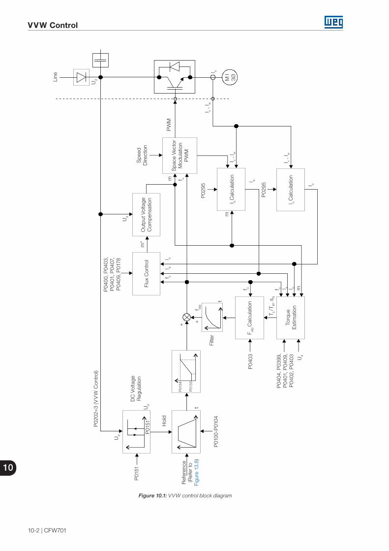
10
VVW Control
10-2 | CFW701
P02
02=
3 (V
VW
Con
trol
)
Ud
P01
51U
d
DC
Vol
tage
R
egul
atio
n
Hol
d
P01
00-P
0104
t
Filte
r
+ +
Ref
eren
ce(R
efer
to
Figu
re 1
3.8)
P01
34
P01
33
P04
03
f slip
F slip
Cal
cula
tion
f o
T L/T
R, s
Rf o l a l o m
Torq
ue
Est
imat
ion
P04
04, P
0399
,P
0401
, P04
09,
P04
02, P
0403 U
d
l o
l o C
alcu
latio
n I v ,
I w
P02
95
l a
I v , I w
l a C
alcu
latio
nm
P02
95
f omP
WM
I v , I w
Spa
ce V
ecto
r M
odul
atio
n
PW
M
Spe
ed
Dire
ctio
n
f ol a
l o
Flux
Con
trol
m*
Ud
Line
Out
put V
olta
ge
Com
pens
atio
n
Ud
P04
00, P
0403
, P
0401
, P04
07,
P04
09, P
0178
l o
M I
3Ø
P01
51
t
Figure 10.1: VVW control block diagram
10
VVW Control
CFW701 | 10-3
10.1 VVW CONTROL
Only three parameters are related to this function: P0139, P0202 and P0397.
However, since the parameters P0139 and P0202 were already presented in the section 9.1 - V/f Control, only the parameter P0397 will be described next.
P0397 – Slip Compensation During Regeneration
Adjustable Range:
0 = Off1 = On
Factory Setting:
1
Properties: cfg and VVW
Access groupsvia HMI:
Description:
It enables or disables the slip compensation during the regeneration in the VVW control mode. Refer to the parameter P0138 in the section 9.1 - V/f Control, for more details on the slip compensation.
10.2 MOTOR DATA
The parameters for the used motor data setting are listed in this group. They must be adjusted according to the motor nameplate data (P0398 to P0407) and by means of the Self-Tuning or from data of the motor data sheet (other parameters).
In this section only the parameters P0399 and P0407 will be presented, the others are presented in the section 11.7 - Motor Data.
P0398 – Motor Service Factor
Refer to the section 11.7 - Motor Data, for more information.
P0399 – Motor Rated Efficiency
Adjustable Range:
50.0 to 99.9 % Factory Setting:
67.0 %
Properties: cfg and VVW
Access groupsvia HMI:
MOTOR
Description:
It sets the motor rated efficiency.
This parameter is important for the VVW control precise operation. The inaccurate setting implies in incorrect calculation of the slip compensation and consequently an imprecise speed control.

10
VVW Control
10-4 | CFW701
P0400 – Motor Rated Voltage
P0401 – Motor Rated Current
P0402 – Motor Rated Speed
P0403 – Motor Rated Frequency
P0404 – Motor Rated Power
P0406 – Motor Ventilation
Refer to the section 11.7 - Motor Data, for more information.
P0407 – Motor Rated Power Factor
Adjustable Range:
0.50 to 0.99 Factory Setting:
0.68
Properties: cfg and VVW
Access groupsvia HMI:
MOTOR
Description:
It is the motor power factor setting, according to the motor nameplate data (cos Ø).
This parameter is important for the VVW control operation. The inaccurate setting will imply in incorrect calculation of the slip compensation.
The default value of this parameter is adjusted automatically when the parameter P0404 is changed. The suggested value is valid for three-phase, IV pole WEG motors. For other motor types the setting must be done manually.
P0408– Run Self-Tuning
P0409 – Motor Stator Resistance (Rs)
P0410 – Motor Magnetizing Current (Im)
Refer to item 11.8.5 - Self-Tuning, for more information.
10
VVW Control
CFW701 | 10-5
10.3 VVW CONTROL MODE START-UP
NOTE!Read the whole CFW701 user's manual before installing, powering or operating the inverter.
Sequence for installation, verification, powering and start-up:
1. Install the inverter: according to the chapter 3 - Installation and Connection, of the CFW701 user's manual, wiring all the power and control connections.
2. Prepare the inverter and apply power: according to the section 5.1 - Prepare for Start-up, of the CFW701 user's manual.
3. Adjust the password P0000=5: according to the section 5.3 - Password Setting in P0000, of this manual.
4. Adjust the inverter to operate with the application line and motor: by means of the “STARTUP” Menu access P0317 and change its content to 1, which makes the inverter initiate the “Oriented Start-up” routine.
The “Oriented Start-up” routine presents on the keypad (HMI) the main parameters in a logical sequence. The setting of these parameters prepares the inverter for operation with the application line and motor. Verify the step by step sequence in the figure 10.2.
The setting of the parameters presented in this operation mode results in the automatic modification of the content of other inverter parameters and/or internal variables, as indicated in the figure 10.2. In this way one gets a stable operation of the control circuit with adequate values to obtain the best motor performance.
During the “Oriented Start-up” routine the “Config” (Configuration) status will be indicated on the keypad (HMI).
Parameters related to the motor:
Program the contents of parameters from P0398 to P0407 directly with the motor nameplate data. Refer to the section 11.7 - Motor Data.
Options for the setting of parameter P0409:
I – Automatic by the inverter, performing the self-tuning routine selected in P0408.II – From the motor test data sheet, supplied by the manufacturer. Refer to item 11.7.1 - Adjustment of the
Parameters P0409 to P0412 Based on the Motor Data Sheet, in this manual.II – Manually, copying the parameters content of another CFW701 that runs an identical motor.
5. Setting of specific parameters and functions for the application: program the digital and analog inputs and outputs, HMI keys, etc., according to the application needs.
For applications:
That are simple, which can use the factory settings programming for the digital and analog inputs and outputs, use the Menu “BASIC”. Refer to item 5.2.2 - Basic Application Menu, of the CFW701 user's manual.
That require only the digital and analog inputs and outputs with programming different from the factory settings, use the Menu “I/O”.
That need functions as Flying Start, Ride-Through, DC Braking, Dynamic Braking, etc., access and modify those function parameters by means of the Menu “PARAM”.

10
VVW Control
10-6 | CFW701
Step Action/Result Indicação no Display
1
- Monitoring Mode. - Press the ENTER/MENU key to get
into the first level of the programming mode.
2 - The PARAM group is selected, press
the or keys to select the STARTUP group.
3 - Press ENTER/MENU when the
group is selected.
4
- The parameter “P0317 – Oriented Start-up” is then selected, press the ENTER/MENU to get into the parameter content.
5 - Change the parameter P0317 to “1 -
Yes”, by using the key.
6 - Press ENTER/MENU to save.
7
- In this moment the Oriented Start-up routine is initiated and the “CONF” status is indicated at the keypad (HMI).
- The parameter “P0000 - Access to Parameters” is selected. Change the password to set the remaining parameters if necessary.
- Press the key to the next parameter.
8
- If necessary, change “P0296 - Line Rated Voltage”. This change will affect P0151, P0153, P0185, P0321, P0322, P0323 and P0400.
- Press the key to the next parameter.
9
- If necessary, change “P0298 - Appl icat ion” parameter. Th is change will affect P0156, P0157, P0158, P0401, P0404 and P0410 (this last one only if P0202 = 0, 1 or 2 - V/f modes). The time and level of the IGBT overload protection will also be affected.
- Press the key to the next parameter.
Step Action/Result Indicação no Display
10
- Set parameter “P0202 - Type of Control” pressing “ENTER/MENU”. Press the key to select the desired option: “[3]=VVW”. Then, press “ENTER/MENU”. There are three options to exit the oriented start-up:1 - Running the Self-tunning;2 - Manual settings of parameters
from P0409 to P0413;3 - Changing P0202 from vector to
V/Hz control. - Press the key to the next
parameter.
11
- If necessary, change “P0398 - Motor Service Factor” parameter. This change will affect the current and the time of the motor overload protection operation.
- Press the key to the next parameter.
12
- If necessary, change “P0399 - Motor Rated Efficiency” parameter.
- Press the key to the nex t parameter.
13
- If necessary, change “P0400 - Motor Rated Voltage” parameter.
- This change corrects the output voltage by the factor “x = P0400/P0296”.
- Press the key to the next parameter.
14
- If necessary, change “P0401 - Motor Rated Current” parameter. This change will affect P0156, P0157, P0158 and P0410.
- Press the key to the next parameter.
15
- If necessary, change “P0404 - Motor Rated Power” parameter. This change will affect P0410.
- Press the key to the next parameter.
16
- If necessary, change “P0403 - Motor Rated Frequency” parameter. This change will affect P0402.
- Press the key to the next parameter.
17
- If necessary, change “P0402 - Motor Rated Speed”. This change will affect P0122 to P0131, P0133, P0134, P0135, P0182, P0208, P0288 and P0289.
- Press the key to the next parameter.
Figure 10.2: VVW mode Oriented Start-up

10
VVW Control
CFW701 | 10-7
Step Action/Result Display indication
18
- If necessary, change “P0406 - Motor Ventilation” parameter.
- Press the key to the next parameter.
19
- If necessary, change “P0407 - Motor Rated Power Factor”.
- Press the key to the next parameter.
20
- In this moment the keypad presents the option to perform “Self-tunning”. The Self-tunning should be performed whenever it is possible. Press “ENTER/MENU” key to access parameter P0408 and press to select the option “1=No rotation”. Refer to item 11.8.5 - Self-Tuning, for more details. Then, press “ENTER/MENU” to start the Self-tunning.
- The keypad will show “CONF” and “RUN” status simultaneously during the self-tunning. The “RUN” status is automatically off and parameter P0408 is automatically set back to zero.
21
- Press BACK/ESC key to finish the start-up routine.
- Press BACK/ESC key again to get back to the monitoring mode.
Figure 10.2 (cont.): VVW mode Oriented Start-up

10
VVW Control
10-8 | CFW701

Vector Control
11
CFW701 | 11-1
11 VECTOR CONTROL
It consists in the control type based on the separation of the motor current into two components:
Flux producing current Id (oriented with the motor electromagnetic flux).
Torque producing current Iq (perpendicular to the motor flux vector).
The Id current is related to the motor electromagnetic flux, while the Iq current is directly related to the torque produced at the motor shaft. With this strategy one gets the so called decoupling, i.e., one can control the motor flux and torque independently by controlling the Id and Iq currents respectively.
Since these currents are represented by vectors that rotate at the synchronous speed, when observed from a stationary referential, a referential transformation is done so that they are changed to the synchronous referential. In the synchronous referential these values become DC values proportional the respective vector amplitudes. This simplifies considerably the control circuit.
When the Id vector is aligned with the motor flux, it can be said that the vector control is orientated. Therefore it is necessary that the motor parameters be correctly adjusted. Some of those parameters must be programmed with the motor nameplate data and others obtained automatically through self-tuning or from the motor data sheet supplied by the manufacturer.
The figure 11.1 presents the block diagram for the sensorless vector control. The information of the speed, as well as of the currents measured by the inverter, will be used to obtain the correct vector orientation. In the vector with encoder control case, the speed is obtained directly from the encoder signal, while in the sensorless vector control there is an algorithm which estimates the speed, based in the output currents and voltages.
The vector control measures the current, separates the flux and torque portions and transforms these variables to the synchronous referential. The motor control is accomplished by imposing the desired currents and comparing them with the actual values.
11.1 SENSORLESS CONTROL
The Sensorless Vector Control is recommended for the majority of the applications, because it allows the operation in a speed variation range of 1:100, speed control with 0.5 % accuracy of rated speed, high starting torque and fast dynamic response.
Another advantage of this control type is the greater robustness against sudden line voltage and load changes, avoiding unnecessary overcurrent trips.
The necessary settings for the good operation of the sensorless vector control are done automatically. Therefore the used motor must be connected to the CFW701 inverter.
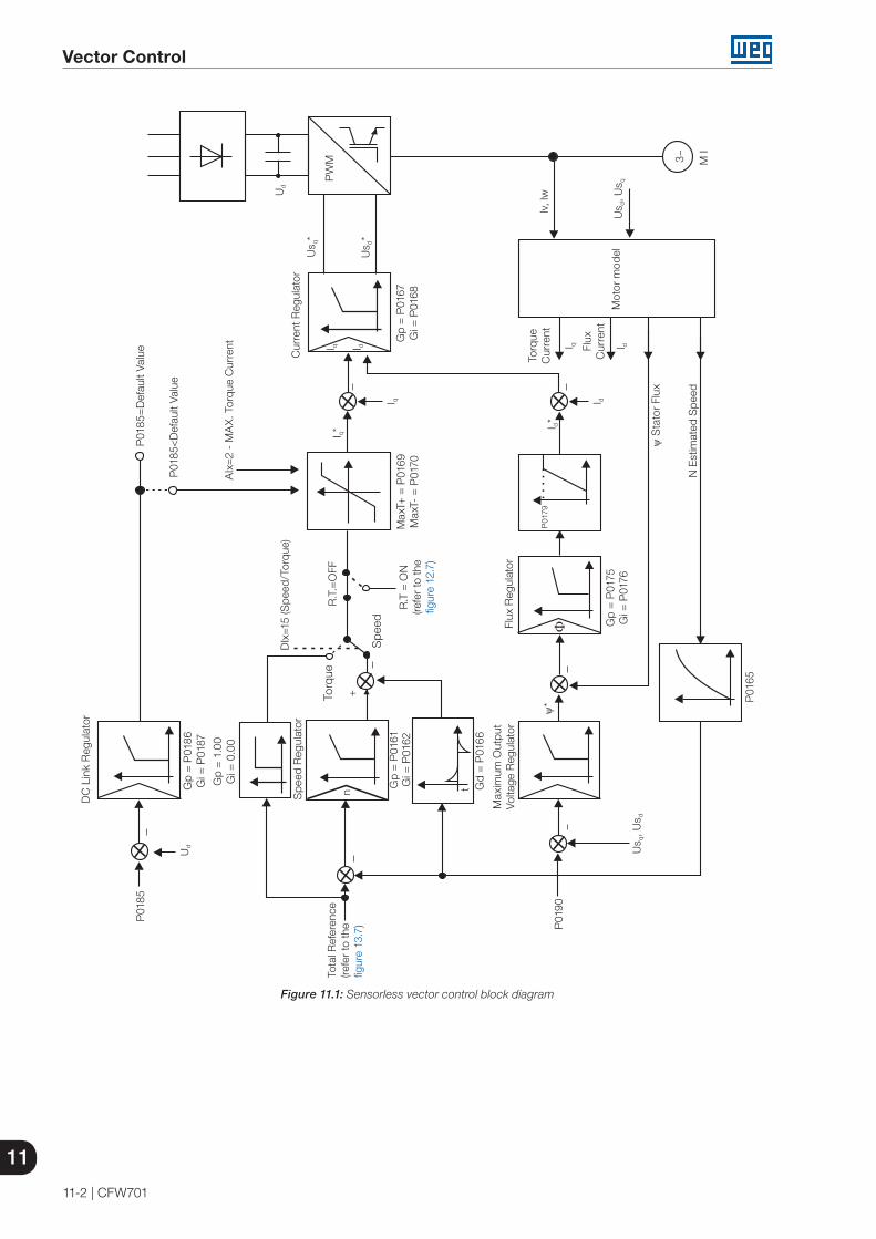
11
Vector Control
11-2 | CFW701
Spe
ed R
egul
ator
DC
Lin
k R
egul
ator
t
Flux
Reg
ulat
or
Max
imum
Out
put
Volta
ge R
egul
ator
Tota
l Ref
eren
ce(re
fer
to th
e fig
ure
13.7
)
Gp
= P
0161
Gi =
P01
62G
p =
P01
67G
i = P
0168
Us d
*
Flux
C
urre
nt
AIx
=2
- M
AX
. Tor
que
Cur
rent
P01
85<
Def
ault
Valu
e
P01
85=
Def
ault
Valu
e
M I
Torq
ue
Cur
rent
PW
M
Us q
*
I dI q
Cur
rent
Reg
ulat
or
I q I d
I q
I q*
I d*
I d
P01
79
Gp
= P
0175
Gi =
P01
76
Gp
= P
0186
Gi =
P01
87
Us q
, Us d
Ud
P01
90
P01
65
P01
85
Gd
= P
0166
Gp
= 1
.00
Gi =
0.0
0
DIx
=15
(Spe
ed/T
orqu
e)
R.T
.=O
FF
R.T
= O
N(re
fer
to th
e fig
ure
12.7
)
Max
T+ =
P01
69M
axT-
= P
0170
n+
N E
stim
ated
Spe
ed
Us d
, Us q
Ud
lv, l
w
Mot
or m
odel
Spe
ed
Torq
ue
ψ S
tato
r Fl
ux
ψ*
3~
Figure 11.1: Sensorless vector control block diagram
Vector Control
11
CFW701 | 11-3
11.2 I/f MODE (SENSORLESS)
NOTE!It is activated automatically at low speeds if P0182>3 and when the Control Mode is Sensorless Vector (P0202=4).
The operation at the low speed region may present instability. In this region the motor operation voltage is also very low, being difficult to be measured accurately.
In order to keep a stable operation of the inverter in that region, the automatic commutation occurs, from sensorless mode to the so called I/f mode, which is a scalar control with imposed current. Scalar control with imposed current means a current control with a constant reference value, adjusted in a parameter and controlling only the frequency in an open loop.
The parameter P0182 defines the speed below which the transition to I/f mode occurs and the parameter P0183 defines the value of the current to be applied to the motor.
The minimum speed recommended for the operation of the Sensorless Vector Mode is 18 rpm for 60 Hz IV pole motors, and 15 rpm for 50 Hz IV pole motors. If P0182 ≤ 3 rpm the inverter will always operate in Sensorless Vector mode, i.e., the I/f function will be disabled. 11.3 SELF-TUNING
Some motor parameters that are not available on the motor nameplate, necessary for the operation of the sensorless vector control, are estimated:
Stator resistance.
Motor flux leakage inductance.
Rotor time constant Tr.
Rated magnetizing current of the motor.
Mechanic time constant of the motor and the driven load.
These parameters are estimated with the application of voltages and currents to the motor.
The parameters related to the regulators used by the vector control, as well as other control parameters, are adjusted automatically in function of the motor parameters estimated through the self-tuning routine. The best self-tuning results are obtained with a preheated motor.
The parameter P0408 controls the self-tuning routine. Depending on the chosen option some parameters can be obtained from tables that are valid for WEG motors.
In the option P0408=1 (No Rotation) the motor remains stopped throughout the self-tuning. The magnetizing current value (P0410) is obtained from a table, valid for WEG motors up to 12 poles.
In the option P0408=2 (Run for Im) the value of P0410 is estimated with the motor rotating and the load decoupled from the motor shaft.

11
Vector Control
11-4 | CFW701
NOTE!Every time that P0408=1 or 2 the parameter P0413 (Mechanic time constant – Tm) will be adjusted for a value close to the motor rotor mechanic time constant. Therefore, the motor rotor inertia (table data valid for WEG motors), the inverter rated voltage and current, are taken into consideration.
If the option P0408=2 (Run for Im) is executed with the load coupled to the motor, an incorrect value of P0410 (Im) may be estimated. This will implicate in estimation error for P0412 (rotor time constant - Tr) and for P0413 (mechanic time constant – Tm). Overcurrent fault (F071) may also occur during the inverter operation.Note: The term “load” includes everything that might be coupled to the motor shaft, for instance, gearbox, inertia disk, etc.
During its execution, the self-tuning routine can be canceled by pressing the key, provided that the values of P0409 through P0413 be all different from zero.
For more details on the self-tuning parameters, refer to item 11.8.5 - Self-Tuning, in this manual.
Alternatives for the acquisition of the motor parameters:
Instead of running the self-tuning, it is possible to obtain the values for P0409 to P0412 in the following manner:
From the motor test data sheet that can be supplied by its manufacturer. Refer to item 11.7.1 - Adjustment of the Parameters P0409 to P0412 Based on the Motor Data Sheet, of this manual.
Manually, by copying the contents of the parameters from another CFW701 inverter that uses an identical motor.
11.4 OPTIMAL FLUX FOR SENSORLESS VECTOR CONTROL
NOTE!Active function only on the Sensorless Vector mode (P0202=4), if P0406=2.
The Optimal Flux function can be used for driving some types of WEG motors (*) making it possible the operation at low speed with rated torque without the need of forced ventilation on the motor. The frequency range for operation is 12:1, i.e., from 5 Hz to 60 Hz for 60 Hz rated frequency motors and from 4.2 Hz to 50 Hz for 50 Hz rated frequency motors.
NOTE!(*) WEG motors that can be used with the Optimal Flux function:
Nema Premium Efficiency. Nema High Efficiency. IEC Premium Efficiency. IEC Top Premium Efficiency. Alto Rendimento Plus.
When this function is activating, the motor flux is controlled in a way to reduce their electric losses on slow speeds. That flux is dependent of the torque current filtered (P0009). The Optimal Flux function is unnecessary in motors with independent ventilation.

Vector Control
11
CFW701 | 11-5
11.5 TORQUE CONTROL
In sensorless vector control mode it is possible to use the inverter in torque control mode instead of using it in speed control mode. In this case the speed regulator must be kept saturated and the imposed torque value is defined by the torque limits in P0169/P0170.
Performance of the torque control: Vector control with encoder:Torque control range: 10 % to 180 %. Accuracy: ± 5 % of the rated torque.
Sensorless vector control:Torque control range: 20 % to 180 %.Accuracy: ± 10 % of the rated torque.Minimum operating frequency: 3 Hz.
When the speed regulator is positively saturated, i.e., forward speed direction defined in P0223/P0226, the value for the torque current limitation is adjusted in P0169. When the speed regulator is negatively saturated, i.e., reverse speed direction, the value for the torque current limitation is adjusted in P0170.
The torque at the motor shaft (Tmotor) in % is given by the formula:(*) The equation below must be used for “+” torque. Replace P0169 by P0170 for “-“ torque.
P0401 x P0169(*) x K 100
(P0401) 2 - P0410 x P0178 2 100
x 100Tmotor =
Where:Nnom = motor synchronous speed,N = motor current speed
K =
1 for N ≤ P0190 x Nnom P0400
Nnom x P0190 for N > P0190 x Nnom
N P0400 P0400
NOTE!For torque control in the sensorless vector mode (P0202=4), observe:
The torque limits (P0169/P0170) must be higher than 30 % to assure the motor starting. After the start and with the motor rotating above 3 Hz, they can be reduced, if necessary, to values below 30 %.
NOTE!The motor rated current must be equivalent to the CFW701 rated current, in order that the torque control has the best possible accuracy.
11
Vector Control
11-6 | CFW701
Settings for the torque control:
Torque limitation:
1. Via parameters P0169, P0170 (through the keypad (HMI or Serial). Refer to item 11.8.6 - Torque Current Limitation.
2. Through the analog inputs AI1, AI2 or AI3. Refer to item 13.1.1 - Analog Inputs, option 2 (maximum torque current).
Speed reference:
3. Set the speed reference 10 %, or more, higher than the working speed. This assures that the speed regulator output remains saturated at the maximum value allowed by the torque limit adjustment.
NOTE!The torque limitation with the saturated speed regulator has also a protection (limitation) function. E.g.: for a winder, when the material being wound brakes, the regulator leaves the saturated condition and starts controlling the motor speed, which will be kept at the speed reference value.
11.6 OPTIMAL BRAKING
NOTE!Only activated on the Vector control mode (P0202=4), when P0184=0, P0185 is smaller than the standard value and P0404 < 21 (75 CV).
NOTE!The occurrence of optimal braking may cause at the motor:
Increase of the vibration level. Increase of the acoustic noise. Increase of the temperature.
Verify the impact of those effects in the application before using the optimal braking.
It is a function that helps the motor controlled braking, eliminating in many cases the need of additional braking IGBT and braking resistor.
The Optimal Braking makes it possible braking the motor with a higher torque than the one obtained with traditional methods, as for instance, the braking by the injection of direct current (DC braking). In the DC braking case, only the losses in the motor rotor are used to dissipate the energy stored as the mechanic load inertia, rejecting the total friction losses. With the Optimal Braking, in the other hand, the total losses in the motor, as well as the total inverter losses, are used. It is possible to get a braking torque roughly 5 times greater than with DC braking.
In the figure 11.2 the Torque x Speed curve of a typical 10 hp/7.5 kW IV pole motor is presented. The braking torque obtained at the rated speed, for an inverter with a torque limit (P0169 and P0170) adjusted in a value equal to the motor rated torque, is supplied by the TB1 point on the figure 11.2. The value of TB1 is on the function of the motor efficiency, and it is defined by the following expression, being despised the attrition losses:
TB1 = 1-η η
Where:η = motor efficiency.
In the figure 11.2 case, the efficiency of the motor for the rated load is η=0.84 (or 84 %), which results in TB1=0.19 or 19 % of the motor rated torque.
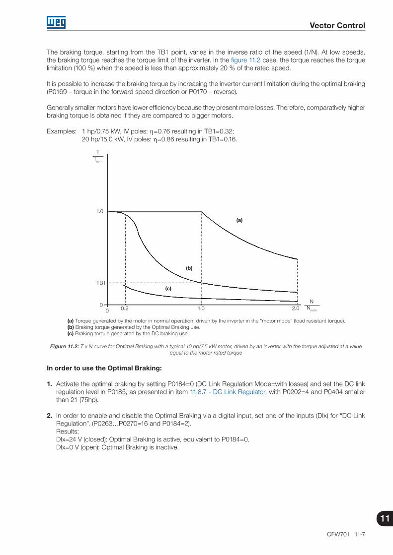
Vector Control
11
CFW701 | 11-7
The braking torque, starting from the TB1 point, varies in the inverse ratio of the speed (1/N). At low speeds, the braking torque reaches the torque limit of the inverter. In the figure 11.2 case, the torque reaches the torque limitation (100 %) when the speed is less than approximately 20 % of the rated speed.
It is possible to increase the braking torque by increasing the inverter current limitation during the optimal braking (P0169 – torque in the forward speed direction or P0170 – reverse).
Generally smaller motors have lower efficiency because they present more losses. Therefore, comparatively higher braking torque is obtained if they are compared to bigger motors.
Examples: 1 hp/0.75 kW, IV poles: η=0.76 resulting in TB1=0.32; 20 hp/15.0 kW, IV poles: η=0.86 resulting in TB1=0.16.
TTnom
NNnom
TB1
1.0
00 0.2 1.0 2.0
(c)
(b)
(a)
(a) Torque generated by the motor in normal operation, driven by the inverter in the “motor mode” (load resistant torque). (b) Braking torque generated by the Optimal Braking use.(c) Braking torque generated by the DC braking use.
Figure 11.2: T x N curve for Optimal Braking with a typical 10 hp/7.5 kW motor, driven by an inverter with the torque adjusted at a value equal to the motor rated torque
In order to use the Optimal Braking:
1. Activate the optimal braking by setting P0184=0 (DC Link Regulation Mode=with losses) and set the DC link regulation level in P0185, as presented in item 11.8.7 - DC Link Regulator, with P0202=4 and P0404 smaller than 21 (75hp).
2. In order to enable and disable the Optimal Braking via a digital input, set one of the inputs (DIx) for “DC Link Regulation”. (P0263…P0270=16 and P0184=2).Results:DIx=24 V (closed): Optimal Braking is active, equivalent to P0184=0.DIx=0 V (open): Optimal Braking is inactive.

11
Vector Control
11-8 | CFW701
11.7 MOTOR DATA
In this group are listed the parameters for the setting of the used motor data. Adjust them according to the motor nameplate data (P0398 to P0407), and by means of the self-tuning routine or with the data existent in the motor data sheet (the other parameters). In the Vector Control mode the parameters P0399 and P0407 are not used.
P0398 – Motor Service Factor
Adjustable Range:
1.00 to 1.50 Factory Setting:
1.00
Properties: cfg
Access groupsvia HMI:
MOTOR
Description:
It is the continuous overload capability, i.e., a reserve of power that gives the motor the capability to withstand working in adverse conditions.
Set it according to the value informed on the motor nameplate.
It affects the motor overload protection.
P0399 – Motor Rated Efficiency
Refer to the section 10.2 - Motor Data, for more details.
P0400 – Motor Rated Voltage
Adjustable Range:
0 to 600 V Factory Setting:
220 V (P0296=0)440 V (P0296=1, 2, 3 or 4)575 V (P0296=5, 6 or 7)
Properties: cfg
Access groupsvia HMI:
MOTOR
Description:
Set it according to the motor nameplate data and to the motor cable wiring in the connection box.
This value cannot be higher than the rated voltage adjusted in P0296 (Line Rated Voltage).
NOTE!In order to validate a new P0400 setting out of the Oriented Start-up Routine it is necessary to cycle the power of the inverter.
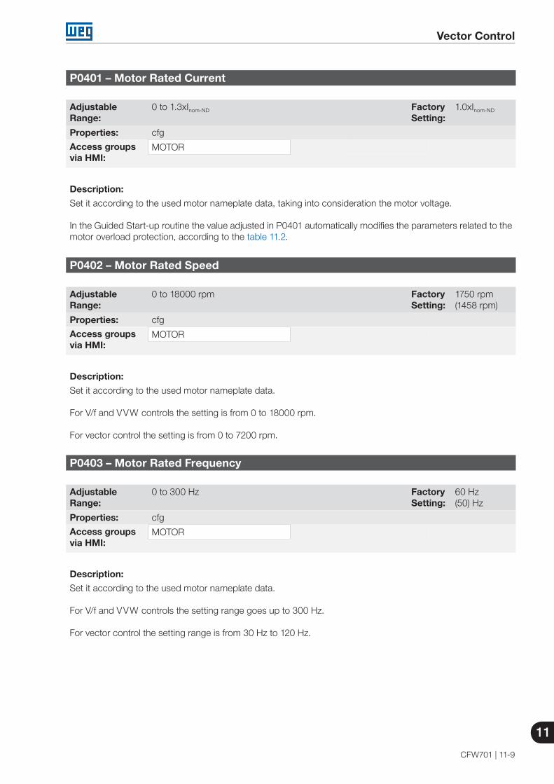
Vector Control
11
CFW701 | 11-9
P0401 – Motor Rated Current
Adjustable Range:
0 to 1.3xInom-ND Factory Setting:
1.0xInom-ND
Properties: cfg
Access groupsvia HMI:
MOTOR
Description:
Set it according to the used motor nameplate data, taking into consideration the motor voltage.
In the Guided Start-up routine the value adjusted in P0401 automatically modifies the parameters related to themotor overload protection, according to the table 11.2.
P0402 – Motor Rated Speed
Adjustable Range:
0 to 18000 rpm Factory Setting:
1750 rpm(1458 rpm)
Properties: cfg
Access groupsvia HMI:
MOTOR
Description:
Set it according to the used motor nameplate data.
For V/f and VVW controls the setting is from 0 to 18000 rpm.
For vector control the setting is from 0 to 7200 rpm.
P0403 – Motor Rated Frequency
Adjustable Range:
0 to 300 Hz Factory Setting:
60 Hz(50) Hz
Properties: cfg
Access groupsvia HMI:
MOTOR
Description:
Set it according to the used motor nameplate data.
For V/f and VVW controls the setting range goes up to 300 Hz.
For vector control the setting range is from 30 Hz to 120 Hz.

11
Vector Control
11-10 | CFW701
P0404 – Motor Rated Power
Adjustable Range:
0 to 25 (refer to the next table) Factory Setting:
Motormax-ND
Properties: cfg
Access groupsvia HMI:
MOTOR
Description:
Set it according to the used motor nameplate data.
Table 11.1: P0404 (Motor Rated Power) setting
P0404 Motor Rated Power (hp)0 0.331 0.502 0.753 1.04 1.55 2.06 3.07 4.08 5.09 5.510 6.011 7.512 10.013 12.514 15.015 20.016 25.017 30.018 40.019 50.020 60.021 75.022 100.023 125.024 150.025 175.0
NOTE!When adjusted via keypad (HMI), this parameter may change the parameter P0329 automatically. Refer to item 12.5.2 - Vector Flying Start.

Vector Control
11
CFW701 | 11-11
P0406 – Motor Ventilation
Adjustable Range:
0 = Self-Ventilated1 = Separated Ventilation2 = Optimal Flux
Factory Setting:
0
Properties: cfg
Access groupsvia HMI:
MOTOR
Description:
During the Oriented Start-up Routine, the value adjusted in P0406 changes the parameters related to the motoroverload automatically, in the following manner:
Table 11.2: Motor overload protection modification in function of P0406
P0406 P0156 (Overl.Curr.100 %) P0157 (Overl.Curr.50 %) P0158 (Overl.Curr.5 %)0 1.05xP0401 0.9xP0401 0.65xP04011 1.05xP0401 1.05xP0401 1.05xP04012 1.05xP0401 1.0xP0401 1.0xP0401
ATTENTION!Refer to the section 11.4 - Optimal Flux for Sensorless Vector Control, for more details on the use of option P0406=2 (Optimal Flux).
P0407 – Motor Rated Power Factor
Refer to the section 10.2 - Motor Data, for more details.
P0408 – Run Self-Tuning
P0409 – Motor Stator Resistance (Rs)
P0410 – Motor Magnetization Current (Im)
P0411 – Motor Flux Leakage Inductance (σls)
P0412 – Lr/Rr Constant (Rotor Time Constant – Tr)
P0413 – Tm Constant (Mechanical Time Constant)
Self-Tuning function parameters. Refer to item 11.8.5 - Self-Tuning.
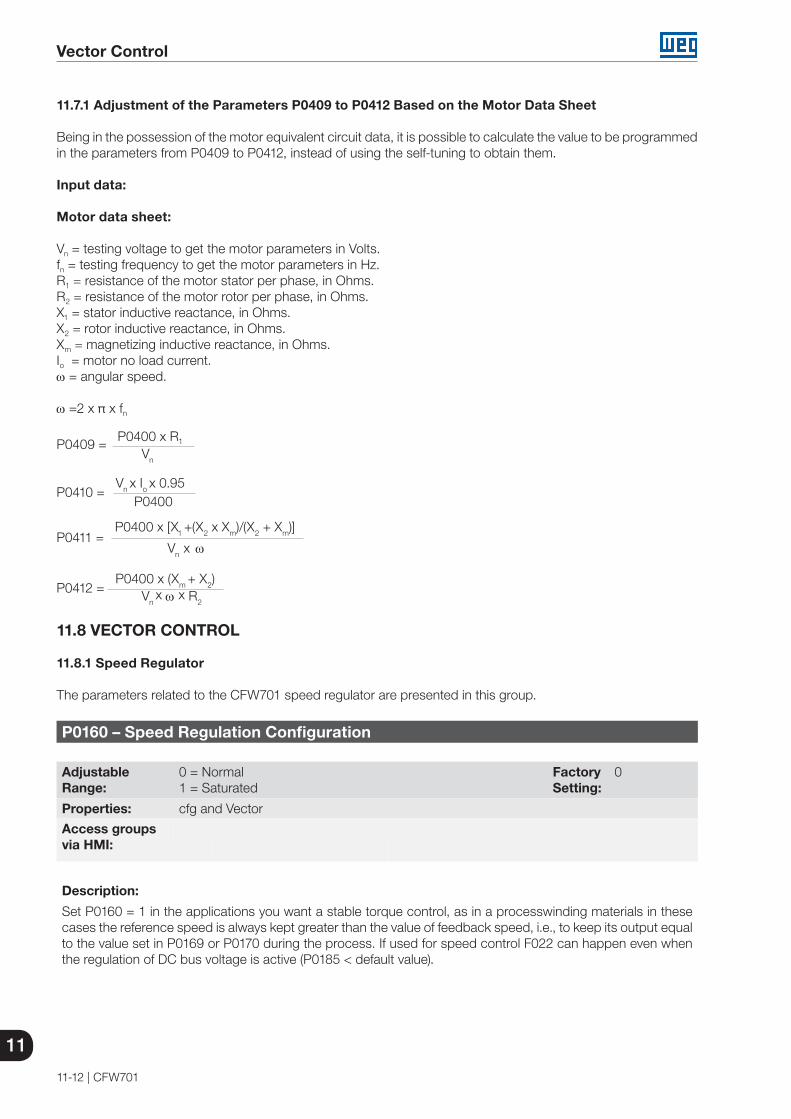
11
Vector Control
11-12 | CFW701
11.7.1 Adjustment of the Parameters P0409 to P0412 Based on the Motor Data Sheet
Being in the possession of the motor equivalent circuit data, it is possible to calculate the value to be programmed in the parameters from P0409 to P0412, instead of using the self-tuning to obtain them.
Input data:
Motor data sheet:
Vn = testing voltage to get the motor parameters in Volts.fn = testing frequency to get the motor parameters in Hz.R1 = resistance of the motor stator per phase, in Ohms.R2 = resistance of the motor rotor per phase, in Ohms.X1 = stator inductive reactance, in Ohms.X2 = rotor inductive reactance, in Ohms.Xm = magnetizing inductive reactance, in Ohms.Io = motor no load current.ω = angular speed.
ω =2 x π x fn
P0409 = P0400 x R1
Vn
P0410 = Vn x Io x 0.95
P0400
P0411 = P0400 x [X1 +(X2 x Xm)/(X2 + Xm)]
Vn x ω
P0412 = P0400 x (Xm + X2)
Vn x ω x R2
11.8 VECTOR CONTROL
11.8.1 Speed Regulator The parameters related to the CFW701 speed regulator are presented in this group.
P0160 – Speed Regulation Configuration
Adjustable Range:
0 = Normal 1 = Saturated
Factory Setting:
0
Properties: cfg and Vector
Access groupsvia HMI:
Description:
Set P0160 = 1 in the applications you want a stable torque control, as in a processwinding materials in these cases the reference speed is always kept greater than the value of feedback speed, i.e., to keep its output equal to the value set in P0169 or P0170 during the process. If used for speed control F022 can happen even when the regulation of DC bus voltage is active (P0185 < default value).

Vector Control
11
CFW701 | 11-13
P0161 – Speed Regulator Proportional Gain
Adjustable Range:
0.0 to 63.9 Factory Setting:
7.4
P0162 – Speed Regulator Integral Gain
Adjustable Range:
0.000 to 9.999 Factory Setting:
0.023
Properties: Vector
Access groupsvia HMI:
Description:
The speed regulator gains are calculated automatically in function of the parameter P0413 (Tm constant).
However, these gains can be adjusted manually in order to optimize the speed dynamic response, which becomes faster with their increase. Yet, if the speed begins to oscillate, they must be reduced.
In a general manner, one can say that the Proportional gain (P0161) stabilizes abrupt speed or reference changes, while the Integral gain (P0162) corrects the error between the reference and the speed, and improves the torque response at low speeds as well.
Procedure for Manual Optimization of the Speed Regulator:
1. Select the acceleration (P0100) and/or deceleration (P0101) time according to the application.
2. Adjust the speed reference for 75 % of the maximum value.
3. Configure an analog output (AOx) for Real Speed, by programming P0251 or P0254 in 2.
4. Disable the speed ramp (Run/Stop=Stop) and wait until the motor stops.
5. Enable the speed ramp (Run/Stop=Run). Observe with an oscilloscope the motor speed signal at the chosen analog output.
6. Verify among the options of the figure 11.3, which waveform best represents the observed signal.
t (s)
(b) Optimized speed regulator
N(V) N(V) N(V)
t (s) t (s)
(a) Low integral gain (P0162) and/or High proportional gain (P0161)
(c) High integral gain (P0162) and/or low proportional gain (P0161)
Figure 11.3 (a) to (c): Speed regulators response types
7. Adjust P0161 and P0162 according to the response type presented in the figure 11.3.
(a) Reduce the proportional gain (P0161) and/or increase the integral gain (P0162).(b) Speed regulator is optimized.(c) Increase the proportional gain and/or reduce the integral gain.

11
Vector Control
11-14 | CFW701
P0163 – Local Reference Offset
P0164 – Remote Reference Offset
Adjustable Range:
-999 to 999 Factory Setting:
0
Properties: Vector
Access groupsvia HMI:
Description:
It adjusts the analog inputs (AIx) speed reference offset. Refer to the figure 13.2.
P0165 – Speed Filter
Adjustable Range:
0.012 to 1.000 s Factory Setting:
0.012 s
Properties: Vector
Access groupsvia HMI:
Description:
It adjusts the speed filter time constant. Refer to the figure 13.2.
NOTE!Generally, this parameter must not be changed. The increment in its value turns the system response slower.
P0166 – Speed Regulator Differential Gain
Adjustable Range:
0.00 to 7.99 Factory Setting:
0.00
Properties: Vector
Access groupsvia HMI:
Description:
The differential action may minimize the effects of the application or removal of load, in the motor speed. Refer to the figure 11.1.
Table 11.3: Differential gain action in the speed regulator
P0166 Diferential Gain Actuation0.00 Inactive
0.01 to 7.99 Active

Vector Control
11
CFW701 | 11-15
11.8.2 Current Regulator
The parameters related to the CFW701 current regulator are presented in this group.
P0167 – Current Regulator Proportional Gain
Adjustable Range:
0.00 to 1.99 Factory Setting:
0.50
P0168 – Current Regulator Integral Gain
Adjustable Range:
0.000 to 1.999 Factory Setting:
0.010
Properties: Vector
Access groupsvia HMI:
Description:
Parameters P0167 and P0168 are adjusted automatically as a function of the parameters P0411 and P0409.
NOTE!Do not change these parameters values.
11.8.3 Flux Regulator
The parameters related to the CFW701 flux regulator are presented next.
P0175 – Flux Regulator Proportional Gain
Adjustable Range:
0.0 to 31.9 Factory Setting:
2.0
P0176 – Flux Regulator Integral Gain
Adjustable Range:
0.000 to 9.999 Factory Setting:
0.020
Properties: Vector
Access groupsvia HMI:
Description:
These parameters are adjusted automatically in function of the parameter P0412. In general, the automatic setting is sufficient and the readjustment is not necessary.
These gains must only be readjusted manually when the flux current signal (Id*) is unstable (oscillating) and compromising the system operation.
NOTE!For gains in P0175 > 12.0 the flux current (Id*) may become unstable.
Note: (Id*) is observed at the analog outputs AO1 and/or AO2, by setting P0251=15 and/or P0254=15.

11
Vector Control
11-16 | CFW701
P0178 – Rated Flux
Adjustable Range:
0 to 120 % Factory Setting:
100 %
P0179 – Maximum Flux
Adjustable Range:
0 to 120 % Factory Setting:
120 %
Properties: Vector
Access groupsvia HMI:
Description:
The parameter P0178 is the flux reference, while the parameter P0179 defines the maximum value for the flux (magnetization) current.
NOTE!These parameters must not be modified.
P0190 – Maximum Output Voltage
Adjustable Range:
0 to 600 V Factory Setting:
0.95 x P0296. Automatic setting during the Oriented Start-up Routine: 0.95xP0400.
Properties: Vector
Access groupsvia HMI:
Description:
This parameter defines the value of the maximum output voltage. Its standard value is defined in the condition of the nominal supply voltage.
The voltage reference used in the regulator “Maximum output voltage” (see the figure 11.1) is directly proportional to the voltage supply.
If this voltage increases, the output voltage will then be able to increase to the adjusted value in the parameter P0400 - Motor Rated Voltage.
If the voltage supply decreases, the maximum output voltage will decrease in the same proportion.

Vector Control
11
CFW701 | 11-17
11.8.4 I/f Control
P0182 – Speed for I/f Control Activation
Adjustable Range:
0 to 90 rpm Factory Setting:
18 rpm
Properties: Sless
Access groupsvia HMI:
Description:
It defines the speed below witch the transition form the sensorless to the control I/f occurs.
The minimum recommended speed for the sensorless vector control operation is 18 rpm for 60 Hz rated frequency IV pole motors and 15 rpm for 50 Hz rated frequency IV pole motors.
NOTE!For P0182 ≤ 3 rpm the I/f function will be disabled and the inverter will remain always in the sensorless vector mode.
P0183 – Current in the I/f Mode
Adjustable Range:
0 to 9 Factory Setting:
1
Properties: Sless
Access groupsvia HMI:
Description:
It defines the current to be applied to the motor when the inverter is operating in the I/f mode, i.e., with the motor speed below the value defined by P0182.
Table 11.4: Current applied in the I/f mode
P0183 Current in the I/f Mode as a Percentage of P0410 (Im)0 100 %1 111 %2 122 %3 133 %4 144 %5 155 %6 166 %7 177 %8 188 %9 200 %

11
Vector Control
11-18 | CFW701
11.8.5 Self-Tuning
In that group are the parameters that are related to the motor and can be estimated by the inverter during the self-tuning routine.
P0408 – Run Self-Tuning
Adjustable Range:
0 = No1 = No Rotation2 = Run for Im
Factory Setting:
0
Properties: cfg, Vector and VVW
Access groupsvia HMI:
MOTOR
Description:By changing from the factory setting to one of the 4 available options, it is possible to estimate the value of the parameters related to the motor being used. Refer to the next description for more details on each option.
Table 11.5: Self-tuning options
P0408 Self-tuning Control Type Estimate Parameter0 No – –1 No Rotation Sensorless vector, VVW P0409, P0410, P0411,
P0412 and P04132 Run for Im Sensorless vector
P0408=1 – No rotation: The motor stands still during the self-tuning. The P0410 value is obtained from a table, valid for WEG motors up to 12 poles.
NOTE!Therefore P0410 must be equal to zero before initiating the self-tuning. If P0410≠0, the self-tuning routine will keep the existent value.
Note: When using another brand of motor P0410 must be adjusted with the adequate value (no load motor current) before initiating the self-tuning.
P0408=2 – Run for Im: The P0410 value is estimated with the motor rotating. It must be executed without load coupled to the motor. P0409, P0411 to P0413 are estimated with the motor standing still.
ATTENTION!If the option P0408=2 (Run for Im) is performed with the load coupled to the motor, an incorrect value of P0410 (Im) may be estimated. This will implicate in estimation error for P0412 (Rotor time constant - Tr) and for P0413 (Mechanic time constant – Tm). Overcurrent fault (F071) may also occur during the inverter operation.
Note: The term “load” includes everything that might be coupled to the motor shaft, for instance, gearbox, inertia disk, etc.

Vector Control
11
CFW701 | 11-19
NOTES! Every time that P0408=1 or 2:
The parameter P0413 (Mechanic time constant – Tm) will be adjusted to a value close to the motor mechanic time constant. Therefore, the motor rotor inertia (table data valid for WEG motors), the inverter rated voltage and current are taken into consideration.
VVW mode – Voltage Vector WEG (P0202=3):In the VVW control self-tuning routine only the value of the stator resistance (P0409) will be obtained. Therefore, the self-tuning will always be performed without rotating the motor.
Better self-tuning results are obtained with the motor warm.
P0409 – Motor Stator Resistance (Rs)
Adjustable Range:
0.000 to 9.999 ohm Factory Setting:
0.000 ohm
Properties: cfg, Vector and VVW
Access groupsvia HMI:
MOTOR
Description:
It is the value estimated by the self-tuning.
NOTE!The P0409 setting determines the value of the current regulator integral gain P0168. The parameter P0168 is recalculated every time the content of P0409 is modified via keypad (HMI).
P0410 – Motor Magnetization Current (Im)
Adjustable Range:
0 to 1.25 x Inom-ND Factory Setting:
Inom-ND
Properties:
Access groupsvia HMI:
MOTOR
Description:
It is the motor magnetization current value.
It can be estimated by the self-tuning routine when P0408=2 (Run for Im) or obtained from an internal table based in standard WEG motors, when P0408=1 (No rotation).
When a standard WEG motor is not used and it is not possible to run the self-tuning with P0408=2 (Run for Im), then adjust P0410 with a value equal to the motor no load current, before initiating the self-tuning.

11
Vector Control
11-20 | CFW701
P0411 – Motor Flux Leakage Inductance (σls)
Adjustable Range:
0.00 to 99.99 mH Factory Setting:
0.00 mH
Properties: cfg and Vector
Access groupsvia HMI:
MOTOR
Description:
It is the value estimated by the self-tuning.
The P0411 setting determines the current regulator proportional gain.
NOTE!When adjusted via the keypad (HMI), this parameter may change the parameter P0167 automatically.
P0412 – Lr/Rr Constant (Rotor Time Constant – Tr)
Adjustable Range:
0.000 to 9.999 s Factory Setting:
0.000 s
Properties: Vector
Access groupsvia HMI:
MOTOR
Description:
The P0412 setting determines the flux regulator gains (P0175 and P0176).
The value of this parameter interferes in the speed accuracy in the sensorless vector control.
Normally the self-tuning is performed with the motor cold. Depending on the motor, the P0412 value may vary with the temperature. Thus, for the sensorless vector control and normal operation with the motor warm, P0412 must be adjusted until the speed of the motor with load (measured at the motor shaft with a tachometer) stays equal to that one indicated on the keypad (HMI) (P0001).
This adjustment must be performed with half the rated speed.
In the sensorless vector control mode the P0175 gain, provided by the self-tuning, will be limited in the range: 3.0 ≤ P0175 ≤ 8.0.

Vector Control
11
CFW701 | 11-21
Table 11.6: Typical rotor constant (Tr ) values for WEG motors
Motor Power(hp) / (kW)
Tr (s)Number of Poles
2 (50 Hz/60 Hz) 4 (50 Hz/60 Hz) 6 (50 Hz/60 Hz) 8 (50 Hz/60 Hz)2 / 1.5 0.19 / 0.14 0.13 / 0.14 0.1 / 0.1 0.07 / 0.075 / 3.7 0.29 / 0.29 0.18 / 0.12 - / 0.14 0.14 / 0.1110 / 7.5 - / 0.38 0.32 / 0.25 0.21 / 0.15 0.13 / 0.1415 / 11 0.52 / 0.36 0.30 / 0.25 0.20 / 0.22 0.28 / 0.2220 / 15 0.49 / 0.51 0.27 / 0.29 0.38 / 0.2 0.21 / 0.2430 / 22 0.70 / 0.55 0.37 / 0.34 0.35 / 0.37 - / 0.3850 / 37 - / 0.84 0.55 / 0.54 0.62 / 0.57 0.31 / 0.32100 / 75 1.64 / 1.08 1.32 / 0.69 0.84 / 0.64 0.70 / 0.56150 / 110 1.33 / 1.74 1.05 / 1.01 0.71 / 0.67 - / 0.67200 / 150 - / 1.92 - / 0.95 - / 0.65 - / 1.03300 / 220 - / 2.97 1.96 / 2.97 1.33 / 1.30 - / -350 / 250 - / - 1.86 / 1.85 - / 1.53 - / -
500 / 375 - / - - / 1.87 - / - - / -
NOTE!When adjusted via the keypad (HMI), this parameter may change automatically the following parameters: P0175, P0176, P0327 and P0328.
P0413 – Tm Constant (Mechanical Time Constant)
Adjustable Range:
0.00 to 99.99 s Factory Setting:
0.00 s
Properties: Vector
Access groupsvia HMI:
MOTOR
Description:
The P0413 setting determines the speed regulator gains (P0161 and P0162).
When P0408=1 or 2, it must be observed:
If P0413=0, the time constant Tm will be obtained in function of the inertia of the programmed motor (table value).
If P0413>0, the value of P0413 will not be changed by the self-tuning.
Sensorless vector control (P0202=4):
When the P0413 value obtained through the self-tuning provides inadequate speed regulator gains (P0161 and P0162), it is possible to change them by setting P0413 via keypad (HMI).
The P0161 gain provided by the self-tuning or through P0413 change, will be limited to the range: 6.0 ≤ P0161 ≤ 9.0.
The P0162 value varies in function of the P0161 value.
In case it be necessary to increase even more these gains, they must be adjusted directly at P0161 and P0162.
Note: Values of P0161>12.0 may turn the torque current (Iq) and the motor speed unstable (oscillating).

11
Vector Control
11-22 | CFW701
11.8.6 Torque Current Limitation
The parameters placed in this group define the torque limitation values.
P0169 – Maximum “+” Torque Current
P0170 – Maximum “-” Torque Current
Adjustable Range:
0.0 to 350.0 % Factory Setting:
125.0 %
Properties: Vector
Access groupsvia HMI:
Description:
These parameters limit the value of the motor current component that produces “+” torque (P0169) or “-” torque (P0170). The setting is expressed as a percentage of rated motor current (P0401).
In case that any Analog Input (AIx) be programmed for the option 2 (Maximum Torque Current), P0169 and P0170 become inactive and the current limitation will be specified by the AIx. In this case the limitation value can be monitored at the parameter correspondent to the programmed AIx (P0018, P0019 or P0020).
In the torque limitation condition the motor current can be calculated by:
+ (P0410)2P0169 or P0170(*) x P0401
100
2
Imotor=
The maximum torque developed by the motor is given by:
2Tmotor(%)=
P0401 x P0169(*) or P0170 x K 100
x100 (P0401)2 - P0410 x P0178
100
Where:Nnom = motor synchronous speed,N = motor current speed
K =
1 for N ≤ P0190 x Nnom P0400
Nnom x P0190 for N > P0190 x Nnom
N P0400 P0400
(*) In case that the torque current limitation be provided by an analog input, replace P0169 or P0170 by P0018, P0019 or P0020 according to the programmed AIx. For more details refer to item 13.1.1 - Analog Inputs.

Vector Control
11
CFW701 | 11-23
11.8.7 DC Link Regulator
For the deceleration of high inertia loads or with short deceleration times, the CFW701 has available the DC Link Regulation function, which avoids the tripping of the inverter by overvoltage in the DC link (F022).
P0184 – DC Link Regulation Mode
Adjustable Range:
0 = With losses1 = Without losses2 = Enable/Disable DIx
Factory Setting:
1
Properties: cfg and Vector
Access groupsvia HMI:
Description:
It enables or disables the Optimal Braking function (section 11.6 - Optimal Braking) in the DC voltage regulation, according to the next table.
Table 11.7: DC link regulation modes
P0184 Action
0 = With losses(Optimal Braking)
The Optimal Braking is active as described at P0185. This assures the minimum possible deceleration time without using dynamic or regenerative braking.
1 = Without losses
Automatic control of the deceleration ramp. The Optimal Braking is inactive. The deceleration ramp is automatically adjusted in order to keep the DC link below the level adjusted in P0185. This procedure avoids the overvoltage fault at the DC link (F022). It can also be used with eccentric loads.
2 = Enable/Disable via DIx DIx = 24 V: Braking actuates as described for P0184=1. DIx = 0 V: The Without Losses Braking stays inactive. The DC link voltage will be controlled
by the parameter P0153 (Dynamic Braking).
P0185 – DC Link Voltage Regulation Level
Adjustable Range:
339 to 400 V585 to 800 V585 to 800 V585 to 800 V585 to 800 V809 to 1000 V809 to 1000 V809 to 1000 V
Factory Setting:
P0296=0: 400 VP0296=1: 800 VP0296=2: 800 VP0296=3: 800 VP0296=4: 800 VP0296=5: 1000 VP0296=6: 1000 VP0296=7: 1000 V
Properties: Vector
Access groupsvia HMI:
Description:
This parameter defines the DC link voltage regulation level during the braking. During the braking, the time of the deceleration ramp is automatically extended, thus avoiding an overvoltage fault (F022). The setting of the DC link regulation can be done in two manners:
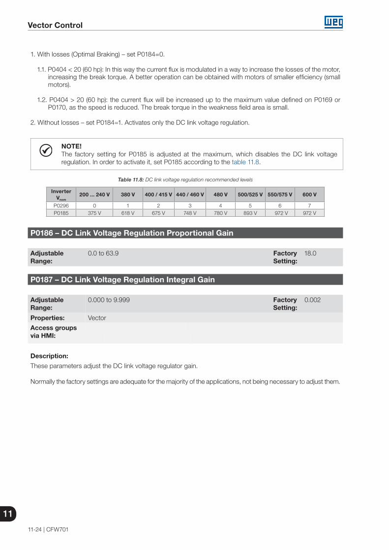
11
Vector Control
11-24 | CFW701
1. With losses (Optimal Braking) – set P0184=0.
1.1. P0404 < 20 (60 hp): In this way the current flux is modulated in a way to increase the losses of the motor, increasing the break torque. A better operation can be obtained with motors of smaller efficiency (small motors).
1.2. P0404 > 20 (60 hp): the current flux will be increased up to the maximum value defined on P0169 or P0170, as the speed is reduced. The break torque in the weakness field area is small.
2. Without losses – set P0184=1. Activates only the DC link voltage regulation.
NOTE!The factory setting for P0185 is adjusted at the maximum, which disables the DC link voltage regulation. In order to activate it, set P0185 according to the table 11.8.
Table 11.8: DC link voltage regulation recommended levels
InverterVnom
200 ... 240 V 380 V 400 / 415 V 440 / 460 V 480 V 500/525 V 550/575 V 600 V
P0296 0 1 2 3 4 5 6 7P0185 375 V 618 V 675 V 748 V 780 V 893 V 972 V 972 V
P0186 – DC Link Voltage Regulation Proportional Gain
Adjustable Range:
0.0 to 63.9 Factory Setting:
18.0
P0187 – DC Link Voltage Regulation Integral Gain
Adjustable Range:
0.000 to 9.999 Factory Setting:
0.002
Properties: Vector
Access groupsvia HMI:
Description:
These parameters adjust the DC link voltage regulator gain.
Normally the factory settings are adequate for the majority of the applications, not being necessary to adjust them.

Vector Control
11
CFW701 | 11-25
11.9 START-UP IN THE VECTOR MODES SENSORLESS
NOTE!Read the whole CFW701 user's manual before installing, powering or operating the inverter.
Sequence for installation, verification, powering and start-up:
1. Install the inverter: according to the chapter 3 - Installation and Connection, of the CFW701 user's manual, wiring all the power and control connections.
2. Prepare the inverter and apply power: according to the section 5.1 - Prepare for Start-up, of the CFW701 user's manual.
3. Adjust the password P0000=5: according to the section 5.3 - Password Setting in P0000, of this manual.
4. Adjust the inverter to operate with the application line and motor: by means of the “STARTUP” Menu access P0317 and change its content to 1, which makes the inverter initiate the “Oriented Start-up” routine.
The “Oriented Start-up” routine presents on the keypad (HMI) the main parameters in a logical sequence. The setting of these parameters prepares the inverter for operation with the application line and motor. Verify the step by step sequence in the figure 11.4.
The setting of the parameters presented in this operation mode results in the automatic modification of the content of other inverter parameters and/or internal variables, as indicated in the figure 11.4. In this way one gets a stable operation of the control circuit with adequate values to obtain the best motor performance.
During the “Oriented Start-up” routine the “Config” (Configuration) status will be indicated on the keypad (HMI).
Parameters related to the motor:
Program the contents of parameters from P0398, P0400 to P0406 directly with the motor nameplate data.
Options for the setting of parameters P0409 to P0412:- Automatic, with the inverter executing the self-tuning routine as selected in one of the P0408 options.- From the motor data sheet supplied by its manufacturer. Refer to the procedure in item 11.7.1 - Adjustment
of the Parameters P0409 to P0412 Based on the Motor Data Sheet, of this manual.- Manually, copying the contents of the parameters from another CFW701 inverter, which uses an identical motor.
5. Setting of specific parameters and functions for the application: set the digital and analog inputs and outputs, HMI keys, etc., according to the application needs.
For applications:
That are simple, which can use the factory settings programming for the digital and analog inputs and outputs, use the Menu “BASIC”. Refer to item 5.2.2 - Basic Application Menu, of the CFW701 user's manual.
That require only the digital and analog inputs and outputs with programming different from the factory settings, use the Menu “I/O”.
That need functions as Flying Start, Ride-Through, DC Braking, Dynamic Braking, etc., access and modify those function parameters by means of the Menu “PARAM”.

11
Vector Control
11-26 | CFW701
Seq. Action/Result Display Indication
1
- Monitoring Mode. - Press ENTER/MENU key to go to
the 1st level of the programming mode.
2 - The PARAM group is selected,
press the or keys to select the STARTUP group.
3 - Press ENTER/MENU when the
group is selected.
4
- The parameter “P0317 - Oriented Start-up” is then selected, press the ENTER/MENU to get into the parameter content.
5 - Change the parameter P0317 to
“1 - Yes”, by using the key.
6 - Press ENTER/MENU to save.
7
- In this moment the Oriented Start-up routine is initiated and the “CONF” status is indicated at the keypad (HMI).
- The parameter “P0000 - Access to Parameters” is selected. Change the password to set the remaining parameters if necessary.
- Press the key to the next parameter.
8
- - If necessary, change “P0296 - Line Rated Voltage”. This change will affect P0151, P0153, P0185, P0321, P0322, P0323 and P0400.
- Press the key to the next parameter.
9
- If necessary, change “P0298 - Application” parameter. This change will affect P0156, P0157, P0158, P0401, P0404 and P0410 (P0410 only will affect if P0202 = 0, 1, 2 or 3). The time and level of the IGBT overload protection will also be affected.
- Press the key to the next parameter.
10
- Set parameter “P0202 - Type of Control” pressing “ENTER/MENU”. Press the
key to select the desired option: “[4]=Sensorless” or “[5]=Encoder”. This change resets P0410. Then, press “ENTER/MENU”.
- There are three options to exit the oriented start-up:1 - Running the Self-tunning;2 - Manual settings of parameters
from P0409 to P0413;3 - Changing P0202 from vector to
scalar control. - Press the key to the next
parameter.
Seq. Action/Result Display Indication
11
- If necessary, change “P0398 - Motor Service Factor” parameter. This change will affect the current and the time of the motor overload protection operation.
- Press the key to the next parameter.
12
- If necessary, change “P0400 - Motor Rated Voltage” parameter.
- This change corrects the output voltage by the factor “x = P0400/P0296”.
- Press the key to the next parameter.
13
- If necessary, change “P0401 - Motor Rated Current” parameter. This change will affect P0156, P0157, P0158 and P0410.
- Press the key to the next parameter.
14
- If necessary, change “P0404 - Motor Rated Power” parameter. This change will affect P0410.
- Press the key to the next parameter.
15
- If necessary, change “P0403 - Motor Rated Frequency” parameter. This change will affect P0402.
- Press the key to the next parameter.
16
- If necessary, change “P0402 - Motor Rated Speed”. This change will affect P0122 to P0131, P0133, P0134, P0135, P0182, P0208, P0288 and P0289.
- Press the key to the next parameter.
17
- If necessary, change “P0406 - Motor Ventilation” parameter.
- Press the key to the next parameter.
18
- In this moment the keypad presents the option to perform “Self-tuning”. The Self-tuning should be performed whenever it is possible. Press “ENTER/MENU” key to access parameter P0408 and press to select the desired option. Refer to item 11.8.5 - Self-Tuning, for more details. Then, press “ENTER/MENU” to start the Self-tuning.The keypad will show “CONF” and “RUN” status simultaneously during the self-tuning. At the end of the Self-Tuning the “RUN” status is automatically set to off and the parameter P0408 is automatically reset.
19
- Press BACK/ESC key to finish the start-up routine.
- Press BACK/ESC key again to get back to the monitoring mode.
Figure 11.4: Vector mode Oriented Start-up

Functions Common to all the Control Modes
12
CFW701 | 12-1
12 FUNCTIONS COMMON TO ALL THE CONTROL MODES
This section describes the functions that are common to all the CFW701 inverter control modes (V/f, VVW and Sensorless).
12.1 RAMPS
The inverter RAMPS functions allow the motor to accelerate and decelerate in a faster or a slower manner.
P0100 – Acceleration Time
P0101 – Deceleration Time
Adjustable Range:
0.0 to 999.0 s Factory Setting:
20.0 s
Properties:
Access groupsvia HMI:
BASIC
Description:
These parameters define the time to accelerate (P0100) lineally from 0 to the maximum speed (defined in P0134) and decelerate (P0101) lineally from the maximum speed down to 0.
Note: The setting 0.0 s means that the ramp is disabled.
P0102 – Acceleration Time 2
P0103 – Deceleration Time 2
Adjustable Range:
0.0 to 999.0 s Factory Setting:
20.0 s
Properties:
Access groupsvia HMI:
Description:
Those parameters allow a second ramp to be configured for the motor acceleration (P0102) or deceleration (P0103), which is activated via an external digital command (defined by P0105). Once this command is activated, the inverter ignores the times of the first ramp (P0100 or P0101) and starts obeying the value adjusted at the second ramp. Refer the example for external command via DIx showed next in the figure 12.1.
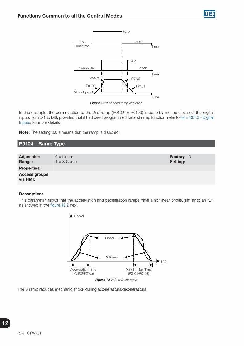
12
Functions Common to all the Control Modes
12-2 | CFW701
open
open
24 V
Time
24 V
Time
P0102
P0100
DIx - Run/Stop
2nd ramp DIx
Motor Speed
P0103
P0101
Time
Figure 12.1: Second ramp actuation
In this example, the commutation to the 2nd ramp (P0102 or P0103) is done by means of one of the digital inputs from DI1 to DI8, provided that it had been programmed for 2nd ramp function (refer to item 13.1.3 - Digital Inputs, for more details).
Note: The setting 0.0 s means that the ramp is disabled.
P0104 – Ramp Type
Adjustable Range:
0 = Linear1 = S Curve
Factory Setting:
0
Properties:
Access groupsvia HMI:
Description:
This parameter allows that the acceleration and deceleration ramps have a nonlinear profile, similar to an “S”, as showed in the figure 12.2 next.
Deceleration Time(P0101/P0103)
Acceleration Time (P0100/P0102)
t (s)S Ramp
Linear
Speed
Figure 12.2: S or linear ramp
The S ramp reduces mechanic shock during accelerations/decelerations.
Functions Common to all the Control Modes
12
CFW701 | 12-3
P0105 – 1st/2nd Ramp Selection
Adjustable Range:
0 = 1st Ramp1 = 2nd Ramp2 = DIx3 = Serial4 = SoftPLC
Factory Setting:
2
Properties: cfg
Access groupsvia HMI:
Description:
It defines the source of the command that will select between the Ramp 1 and the Ramp 2.
Notes:
“Ramp 1” means that the acceleration and deceleration ramps are following the values programmed in P0100 and P0101.
“Ramp 2” means that the acceleration and deceleration ramps are following the values programmed in P0102 and P0103.
It is possible to monitor the set of ramps being used in a defined moment at the parameter P0680 (Logical status).
12.2 SPEED REFERENCES
This parameter group makes it possible that the reference values for the motor speed and for the functions JOG, JOG+ and JOG- be established. It is also possible to define if the reference value will be kept when the inverter is switched off or disabled. For more details refer to the figures 13.7 and 13.8.
P0120 – Speed Reference Backup
Adjustable Range:
0 = Inactive1 = Active
Factory Setting:
1
Properties:
Access groupsvia HMI:
Description:
This parameter defines if the speed reference backup function is active or inactive.
If P0120=Inactive, then the inverter will not save the speed reference when it is disabled. Thus, when the inverter is enabled again the speed reference will assume the value of the minimum speed limit (P0133).
This backup function applies to the references via keypad (HMI), Serial, SoftPLC.

12
Functions Common to all the Control Modes
12-4 | CFW701
P0121 – Keypad Reference
Adjustable Range:
0 to 18000 rpm Factory Setting:
90 rpm
Properties:
Access groupsvia HMI:
Description:
When the and HMI keys are active (P0221 or P0222=0), this parameter sets the value of the motor speed reference.
The value of P0121 will be kept with the last adjusted value when the inverter is disabled or powered off, provided that the parameter P0120 is configured as Active (1).
P0122 – JOG Speed Reference
Adjustable Range:
0 to 18000 rpm Factory Setting:
150 rpm(125 rpm)
Properties:
Access groupsvia HMI:
Description:
During the JOG command the motor accelerates up to the value defined in P0122 following the adjusted acceleration ramp.
The source of the JOG command is defined in the parameters P0225 (Local Situation) or P0228 (Remote Situation).
If the JOG command source has been defined for the digital inputs (DI1 to DI8), one of these inputs must be programmed as presented in the table 12.1.
Table 12.1: JOG command via digital input selection
Digital Input ParametersDI1 P0263 = 6 (JOG)DI2 P0264 = 6 (JOG)DI3 P0265 = 6 (JOG)DI4 P0266 = 6 (JOG)DI5 P0267 = 6 (JOG)DI6 P0268 = 6 (JOG)DI7 P0269 = 6 (JOG)DI8 P0270 = 6 (JOG)
For more details refer to the figure 13.5 (h).
The speed direction is defined by the parameters P0223 or P0226.
The JOG command is effective only with the motor stopped.
For the JOG+ refer to the description below.

Functions Common to all the Control Modes
12
CFW701 | 12-5
P0122 – JOG+ Speed Reference
P0123 – JOG- Speed Reference
Adjustable Range:
0 to 18000 rpm Factory Setting:
150 rpm(125 rpm)
Properties: Vector
Access groupsvia HMI:
Description:
The JOG+ or JOG- commands are always carried out via digital inputs.
One DIx input must be programmed for JOG+ and another for JOG- as presented in the table 12.2 next:
Table 12.2: Selection of the JOG+ and JOG- commands via digital inputs
Digital InputFuntion
JOG+ JOG -DI1 P0263=10 P0263=11DI2 P0264=10 P0264=11DI3 P0265=10 P0265=11DI4 P0266=10 P0266=11DI5 P0267=10 P0267=11DI6 P0268=10 P0268=11DI7 P0269=10 P0269=11DI8 P0270=10 P0270=11
During the JOG+ or JOG- commands the values of P0122 and P0123 are, respectively, added or subtracted from the speed reference to generate the total reference (refer to the figure 13.7).
For the JOG option refer to the previous parameter description.
12.3 SPEED LIMITS
The parameters of this group have the purpose of acting as motor speed limits.
P0132 – Maximum Overspeed Level
Adjustable Range:
0 to 100 % Factory Setting:
10 %
Properties: cfg
Access groupsvia HMI:
Description:
This parameter sets the highest speed allowed for the motor to operate, and must be adjusted as a percentage of the maximum speed limit (P0134).
When the actual speed exceeds the value of P0134 + P0132 longer than 20 ms, the CFW701 will disable the PWM pulses and indicate the fault (F150).
In order to disable this function, set P0132=100 %.
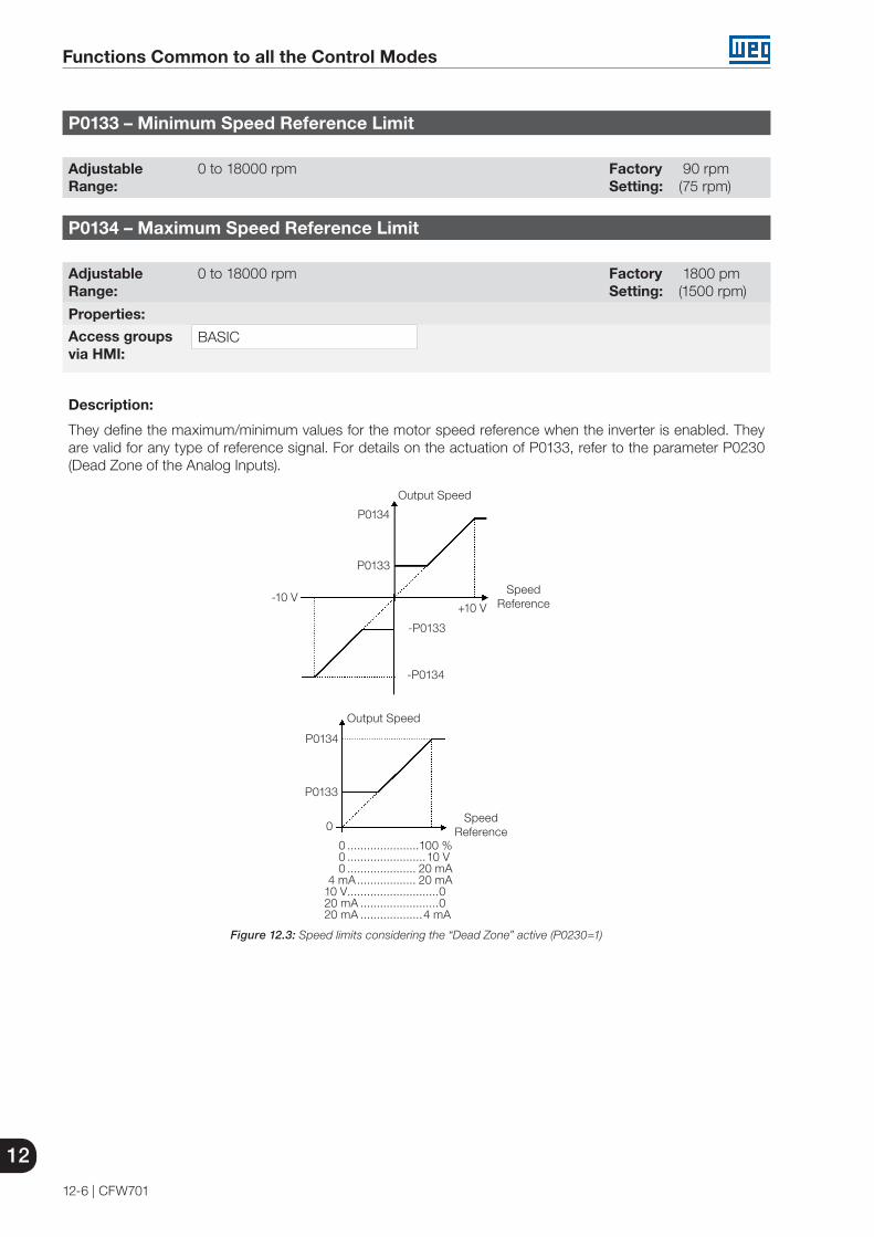
12
Functions Common to all the Control Modes
12-6 | CFW701
P0133 – Minimum Speed Reference Limit
Adjustable Range:
0 to 18000 rpm Factory Setting:
90 rpm(75 rpm)
P0134 – Maximum Speed Reference Limit
Adjustable Range:
0 to 18000 rpm Factory Setting:
1800 pm(1500 rpm)
Properties:
Access groupsvia HMI:
BASIC
Description:
They define the maximum/minimum values for the motor speed reference when the inverter is enabled. They are valid for any type of reference signal. For details on the actuation of P0133, refer to the parameter P0230 (Dead Zone of the Analog Inputs).
-10 VSpeed
Reference
Output Speed
Speed Reference
P0134
P0133
-P0133
-P0134
+10 V
P0134
P0133
0
0 ......................100 % 0 ........................10 V 0 ..................... 20 mA 4 mA .................. 20 mA10 V ............................020 mA ........................020 mA ...................4 mA
Output Speed
Figure 12.3: Speed limits considering the “Dead Zone” active (P0230=1)
Functions Common to all the Control Modes
12
CFW701 | 12-7
12.4 ZERO SPEED LOGIC
This function allows the configuration of a speed in which the inverter will enter a stop condition (general disable).
P0217 – Zero Speed Disable
Adjustable Range:
0 = Inactive1 = Active
Factory Setting:
0
Properties: cfg
Access groupsvia HMI:
Description:
When active, it disables the inverter after the speed reference (N*) and the actual speed (N) become lower than the value adjusted in the parameter P0291.
The inverter is enabled again when one of the conditions defined by the parameter P0218 is satisfied.
DANGER!Be careful when approaching the motor while it is in the disable condition. It may get back to operation at any moment because of the process conditions. In case you want to handle or perform any type of maintenance, remove power from the inverter.
P0218 – Condition to Leave the Zero Speed Disable
Adjustable Range:
0 = Reference or Speed1 = Reference
Factory Setting:
0
Properties:
Access groupsvia HMI:
Description:
It specifies if the condition to leave the zero speed disable will be only the speed reference or also the actual speed.
Table 12.3: Condition to leave the N=0 disable
P0218(P0217 = 1)
Inverter Leaves the Condition of Disable by N=0
0 P0001 (N*) > P0291 or
P0002 (N) > P0291
1 P0001 (N*) > P0291
12
Functions Common to all the Control Modes
12-8 | CFW701
P0219 – Delay for Zero Speed Disable
Adjustable Range:
0 to 999 s Factory Setting:
0 s
Properties:
Access groupsvia HMI:
Description:
It defines whether or not the Zero Speed Disable function will be timed.
If P0219=0, the function works without timing.
If P0219>0, the function will be configured with timing, and the counting of the time adjusted in this parameter will be initiated after the Speed Reference and the Actual Motor Speed become lower than the value adjusted in P0291. When the counting reaches the time defined in P0219, the inverter will be disabled. If during the time counting any of the conditions that cause the zero speed disable ceases being fulfilled, then the time counting will be reset and the inverter continues enabled.
P0291 – Zero Speed Zone
Refer to item 13.1.4 - Digital Outputs / Relays, for more details.
12.5 FLYING START / RIDE-THROUGH
The FLYING START function allows starting a motor that is spinning freely, accelerating it from the speed it is found.
The other function, RIDE-THROUGH, allows the recovery of the inverter, without being disabled by undervoltage, when a failure in the voltage supply occurs.
Since these functions work in different manners depending on the used control mode (V/f, VVW or Vector), they will be described in full detail next, for each one of the modes.
P0320 – Flying Start/Ride-Through
Adjustable Range:
0 = Off1 = Flying Start2 = Flying Start / Ride-Through3 = Ride-Through
Factory Setting:
0
Properties: cfg
Access groupsvia HMI:
Description:
The parameter P0320 selects the functions Flying Start and Ride-Through use. More details in the subsequent sections.
Functions Common to all the Control Modes
12
CFW701 | 12-9
12.5.1 V/f or VVW Flying Start
In the V/f or VVW modes, the inverter imposes a fixed frequency at the start, defined by the speed reference, and applies a voltage ramp defined at the parameter P0331. The Flying Start function will be activated after the time adjusted in P0332 elapses (to allow the motor demagnetization), every time a “Run” command is driven.
12.5.2 Vector Flying Start
12.5.2.1 P0202=4
The behavior of the Flying Start function (FS) in the sensorless mode during acceleration and reacceleration can be understood from the figure 12.4.
The figure 12.4 (b) shows the behavior of the speed reference when the FS function is started with stopped motor shaft and small P0329 value (not optimized).
Operation analysis:
1. The frequency correspondent to the P0134 adjustment is applied, with approximately the motor nominal current (I/f control).
2. The frequency is reduced down to zero using the ramp given by: P0329 x P0412.
3. If the speed is not found during this frequency scan, a new scan in the opposite speed direction is initiated, in which the frequency goes from -P0134 to zero. After this second scan the FS is finished and the control mode changes to vector sensorless.
The figure 12.4 (c) shows the speed reference when the FS function is initiated with the motor shaft already running in the desired direction, or with stopped shaft and an already optimized P0329.
Operation analysis:
1. The frequency correspondent to the P0134 adjustment is applied, with approximately the motor nominal current.
2. The frequency is reduced using the ramp given by: P0329 x P0412 until reaching the motor speed.
3. In this moment the control mode changes to vector sensorless.
NOTE!In order that the motor speed is found in the first scan, proceed with the P0329 setting in the following manner:
1. Increase P0329 using 1.0 steps.
2. Enable the inverter and observe the motor shaft movement during the FS process.
3. If the shaft rotates in both directions, stop the motor and repeat the steps 1 and 2.
NOTE!The used parameters are P0327 to P0329 and the not used ones are P0182, P0331 and P0332.
NOTE!When the general enable command is activated, the motor magnetization will not occur.
NOTE!For a better performance of the function, the activation of the braking without losses is recommended by setting the parameter P0185 according to the table 11.8.

12
Functions Common to all the Control Modes
12-10 | CFW701
P0327 – FS I/f Current Ramp
Adjustable Range:
0.000 to 1.000 s Factory Setting:
0.070 s
Description:
It defines the time for the I/f current to change from 0 to the level used in the frequency sweep (f). It is determined by: P0327=P0412/8.
P0328 – Flying Start Filter
Adjustable Range:
0.000 to 1.000 s Factory Setting:
0.085 s
Description:
It establishes the time of permanence in the condition that indicates that the speed of the motor was found. It is defined by: P0328=(P0412/8 + 0.015 s).
P0329 – FS I/f Frequency Ramp
Adjustable Range:
2.0 to 50.0 Factory Setting:
6.0
Properties: Sless
Access groupsvia HMI:
Description:
It defines the rate of frequency variation used in the motor speed search.
P0329 is determined in function of P0404, as showed in the next table:
Table 12.4: P0329 value in function of P0404
P0404 0...20 21...23 24...25P0329 6.0 7.0 8.0
The frequency variation rate is determined by: (P0329 x P0412).

Functions Common to all the Control Modes
12
CFW701 | 12-11
H. Geral (c/ G/P=ON) ou G/P( c/ HG=ON)
+24 v
tempo
(c)
(a)
(d)
4xP412 1s
P134
n*
N P0329xP0412
tempo
-P134
(b)
4xP412 1s 2xP412
P329xP412
n*
N P001
tempo
P003 P327
tempo
P134
I/f Vetorial
I/f
I = 0.9 x P0401
Vetorial
N
N
P0001P0134
P0134
n*
n*N
N
P0327
-P0134
Vector
Vector
time
+24 V
P0329xP0412
General Enable (witn Run/Stop = ON) or Run/Stop (with General Enable = ON)
P0329xP0412
4xP0412
4xP04122xP0412
P0003
1s
N
N
1s
I/f
I/f
time
time
time
I = 0.9 x P0401
(a)
(b)
(c)
(d)
Figure 12.4 (a) to (d): Influence of P0327 and P0329 during Flying Start (P0202 = 4)
If it is wished to deactivate momentarily the Flying Start function, one can program one of the digital inputs P0263 to P0270 as 15 (Disab.FlyStart). Refer to item 13.1.3 - Digital Inputs.

12
Functions Common to all the Control Modes
12-12 | CFW701
12.5.3 VVW or V/f Ride-Through
The Ride-Through function in the V/f mode will disable the output pulses (IGBT) of the inverter as soon as the input voltage reaches a value below the undervoltage level. The undervoltage fault (F021) does not occur and the DC link voltage will decrease slowly until the line voltage returns.
If the line takes too long to return (more than 2 seconds), the inverter may indicate F021 (DC link undervoltage). If the line voltage returns before a fault, the inverter will enable the pulses again, imposing the speed reference instantaneously (as in the Flying Start function) and applying a voltage ramp with the time defined by P0331. Refer to the figures 12.5 (a) and (b).
DC Link Voltage
F021 Level
Output Pulses
Output Voltage
0 V
Output Speed (P0002)
0 rpm
Line Returns
P0332Enabled
Disabled
P0331
Disabled
Output Pulses
Time adjusted in P0332
Output Voltage
0 V
Output Speed (P0002)
0 rpm
Line Returns
Enabled
P0332
P0331
F021 Level
DC Link Voltage
(a) with the line returning before the time adjusted in P0332 (b) with the line returning after the time adjusted in P0332, but before 2 s (for P0332 ≤ 1 s), or before 2 x P0332
(for P0332 > 1 s)
Figure 12.5 (a) and (b): Ride-Through actuation in V/f or VVW modes
The actuation of the Ride-Through function can be visualized at the outputs DO1/RL1, DO2, DO3, DO4 and/or DO5 (P0275 to P0279), provided that they have been programmed in “22=Ride-Through”.
P0331 – Voltage Ramp
Adjustable Range:
0.2 to 60.0 s Factory Setting:
2.0 s
Properties: V/f and VVW
Access groupsvia HMI:
Description:
This parameter sets the necessary time for the output voltage to reach the rated voltage value.
It is used by the Flying Start function as well as by the Ride-Through function (both in V/f or VVW modes), together with the parameter P0332.

Functions Common to all the Control Modes
12
CFW701 | 12-13
P0332 – Dead Time
Adjustable Range:
0.1 to 10.0 s Factory Setting:
1.0 s
Properties: V/f and VVW
Access groupsvia HMI:
Description:
The parameter P0332 sets the minimum time that the inverter will wait to activate the motor again, which is necessary for the motor demagnetization.
In the Ride-Through function case, the time is counted starting from the line drop. However in the Flying Start function actuation, the counting begins after the “Run/Stop=Run” command is given.
For the correct operation, this time must be adjusted to twice the motor rotor constant (see table available at P0412 in item 11.8.5 - Self-Tuning).
12.5.4 Vector Ride-Through
Different from the V/f and VVW modes, in the vector mode the Ride-Through function tries to regulate the DC link voltage during the line failure. The energy necessary to keep the aggregate working is obtained from the motor kinetic energy (inertia) by means of its deceleration. Thus, at the line return the motor is reaccelerated to the speed defined by the reference.
After the line failure (t0), the DC link voltage (Ud) starts diminishing according to a rate depending on the motor load condition, being able to reach the undervoltage level (t2) if the Ride-Through function is not working. The typical necessary time for this to occur, with rated load, is from a magnitude of 5 to 15 ms.
With the Ride-Through function active, the line loss is detected when the Ud voltage reaches a value below the “DC Link Power Loss” value (t1), defined at the parameter P0321. The inverter initiates a controlled deceleration of the motor immediately, regenerating energy to the DC link in order to keep the motor operating with the Ud voltage regulated at the value “DC Link Ride-Through” (P0322).
In case that the line does not return, the aggregate remains in this condition the longest possible time (depends on the energetic balance) until undervoltage (F021 in t5) occurs. If the line returns before the undervoltage occurrence (t3), the inverter will detect its return when the Ud voltage reaches the “DC Link Power Back” (t4) level, defined at the parameter P0323. The motor is then reaccelerated, following the adjusted ramp, from the actual speed value to the value defined by the speed reference (P0001) (refer to the figure 12.6).

12
Functions Common to all the Control Modes
12-14 | CFW701
F021
t0 t1 t2 t3 t4 t5 t
Ud
Nominal
Return (P0323)Loss (P0321)
Ride-Through (P0322)
Undervoltage (75 %)
Figure 12.6: Ride-Through function actuation in vector mode
t0 – Line loss. t1 – Line loss detection. t2 – Undervoltage actuation (F021 without Ride-Through). t3 – Line return. t4 – Line return detection. t5 – Undervoltage actuation (F021 with Ride-Through).
If the line voltage produces an Ud voltage between the values adjusted in P0322 and P0323, the fault F150 may occur, the values of P0321, P0322 and P0323 must be readjusted.
NOTE!When one of the functions, Ride-Through or Flying Start, is activated, the parameter P0357 (Line Phase Loss Time) is ignored, regardless of the adjusted time.
NOTE!Cautions with the application:
Use oversized high-speed fuses or regular fuses to limit the inrush current when the line returns.
NOTE!The Ride-Through function activation occurs when the power supply voltage is lower than the value (P0321/1.35). Ud=Vac x 1.35

Functions Common to all the Control Modes
12
CFW701 | 12-15
P0321 – DC Link Power Loss
Adjustable Range:
178 to 282 V308 to 616 V308 to 616 V308 to 616 V308 to 616 V425 to 737 V425 to 737 V425 to 737 V
Factory Setting:
P0296 = 0: 252 VP0296 = 1: 436 VP0296 = 2: 459 VP0296 = 3: 505 VP0296 = 4: 551 VP0296 = 5: 602 VP0296 = 6: 660 VP0296 = 7: 689 V
P0322 – DC Link Ride-Through
Adjustable Range:
178 to 282 V308 to 616 V308 to 616 V308 to 616 V308 to 616 V425 to 737 V425 to 737 V425 to 737 V
Factory Setting:
P0296 = 0: 245 VP0296 = 1: 423 VP0296 = 2: 446 VP0296 = 3: 490 VP0296 = 4: 535 VP0296 = 5: 585 VP0296 = 6: 640 VP0296 = 7: 668 V
P0323 – DC Link Power Back
Adjustable Range:
178 to 282 V308 to 616 V308 to 616 V308 to 616 V308 to 616 V425 to 737 V425 to 737 V425 to 737 V
Factory Setting:
P0296 = 0: 267 VP0296 = 1: 462 VP0296 = 2: 486 VP0296 = 3: 535 VP0296 = 4: 583 VP0296 = 5: 638 VP0296 = 6: 699 VP0296 = 7: 729 V
Properties: Vector
Access groupsvia HMI:
Description:
P0321 - defines the Ud voltage level under which the line loss will be detected.
P0322 - defines the Ud voltage level that the inverter will try to keep regulated, so that the motor keeps operating.
P0323 - defines the Ud voltage level at which the inverter will identify the return of the line, and from where the motor must be reaccelerated.
NOTE!These parameters work together with the parameters P0325 and P0326 for the Ride-Through in vector control.

12
Functions Common to all the Control Modes
12-16 | CFW701
P0325 – Ride-Through Proportional Gain
Adjustable Range:
0.0 to 63.9 Factory Setting:
22.8
P0326 – Ride-Through Integral Gain
Adjustable Range:
0.000 to 9.999 Factory Setting:
0.128
Properties: Vector
Access groupsvia HMI:
Description:
These parameters configure the vector mode Ride-Through PI controller, which is responsible for keeping the DC link voltage at the level set in P0322.
Ud
P0325, P0326
R.T. Regulator
Ud Ride-Through(P0322)
Block diagram input Figure 11.1
-
Figure 12.7: Ride-Through PI controller
Normally the factory settings for P0325 and P0326 are adequate for the majority of the applications. Do not change these parameters.

Functions Common to all the Control Modes
12
CFW701 | 12-17
12.6 DC BRAKING
NOTE!The DC Braking at start does not act when the Flying Start function is active (P0320=1 or 2).
The DC Braking consists in the application of direct current to the motor, allowing its fast stopping.
Table 12.5: Parameters related to the DC braking
Control Mode DC Braking at Starting DC Braking at StoppingV/f scalar P0299 and P0302 P0300, P0301 and P0302
VVW P0302 and P0299 P0300, P0301 and P0302Sensorless Vector P0299 and P0372 P0300, P0301 and P0372
P0299 - Starting DC-Braking Time
Adjustable Range:
0.0 to 15.0 s Factory Setting:
0.0 s
Properties: V/f, VVW and Sless
Access groupsvia HMI:
Description:
This parameter sets the DC braking time at starting.
INJECTION OF DIRECT CURRENT AT STARTING
Motor Speed
Time
DC Braking
Run
Stop
P0299 P0302/P0372
(V/f, VVW)/(Sensorless)
Time
Figure 12.8: DC braking operation at starting

12
Functions Common to all the Control Modes
12-18 | CFW701
P0300 – Stopping DC-Braking Time
Adjustable Range:
0.0 to 15.0 s Factory Setting:
0.0 s
Properties: V/f, VVW and Sless
Access groupsvia HMI:
Description:
This parameter sets the DC braking time at stopping.
The figure 12.9 presents the DC braking operation via ramp disabling (refer to P0301).
(a) V/f scalar
P0300Motor Speed
P0301
DEAD TIME
Open
Time
DIx - Run/Stop
+24 V
(b) VVW and Sensorless Vector
P0300
Open
DIx - Run/Stop
DC Current Injection
Time
+24 V
P0301
Motor Speed
Figure 12.9 (a) and (b): DC braking operation at the ramp disabling (via ramp disable)

Functions Common to all the Control Modes
12
CFW701 | 12-19
The figure 12.10 presents the DC braking operation via general disabling. This condition does only work in the V/f scalar mode.
P0300
Time
+24 V
Motor Speed
Dead Time
Open
DIx - General Enable
Figure 12.10: DC braking operation via general disabling – V/f mode
For the V/f scalar control mode there is a “dead time” (motor rotates free), before starting the DC braking. This time is necessary to the demagnetization of the motor and it is proportional to its speed.
During the DC braking the inverter indicates the “RUN” status at the keypad (HMI).
During the braking process, if the inverter is enabled, the braking is interrupted and the inverter will operate normally again.
ATTENTION!The DC braking may continue active after the motor has already stopped. Be careful with the motor thermal sizing for short period cyclic braking.
P0301 – DC-Braking Speed
Adjustable Range:
0 to 450 rpm Factory Setting:
30 rpm
Properties: V/f, VVW and Sless
Access groupsvia HMI:
Description:
This parameter establishes the beginning point for the DC braking application at stopping. Refer to the figures 12.9 (a) and (b).

12
Functions Common to all the Control Modes
12-20 | CFW701
P0302 – DC-Braking Voltage
Adjustable Range:
0.0 to 10.0 % Factory Setting:
2.0 %
Properties: V/f and VVW
Access groupsvia HMI:
Description:
This parameter adjusts the DC voltage (braking torque) applied to the motor during the braking.
The adjustment must be done by increasing gradually the P0302 value, which varies from 0 to 10 % of the rated voltage, until getting the desired braking.
This parameter works only for the V/f scalar and VVW control modes.
P0372 – DC-Braking Current for Sensorless
Adjustable Range:
0.0 to 90.0 % Factory Setting:
40.0 %
Properties: Sless
Access groupsvia HMI:
Description:
This parameter adjusts the current level (DC braking torque) applied to the motor during the braking.
The programmed current level is a percentage of the inverter rated current.
This parameter works only in the Sensorless Vector control mode.

Functions Common to all the Control Modes
12
CFW701 | 12-21
12.7 SKIP SPEED
The parameters of this group prevent the motor from operating permanently at speed values where, for instance, the mechanic system enters in resonance (causing exaggerated vibration or noise).
P0303 – Skip Speed 1
Adjustable Range:
0 to 18000 rpm Factory Setting:
600 rpm
P0304 – Skip Speed 2
Adjustable Range:
0 to 18000 rpm Factory Setting:
900 rpm
P0305 – Skip Speed 3
Adjustable Range:
0 to 18000 rpm Factory Setting:
1200 rpm
P0306 – Skip Band
Adjustable Range:
0 to 750 rpm Factory Setting:
0 rpm
Properties:
Access groupsvia HMI:
Description:
This actuation of these parameters occurs as presented in the figure 12.11 next.
The passage through the avoided speed range (2 x P0306) takes place by means of the acceleration/deceleration ramps.
The function does not operate properly if two bands of “Skip Speed” overlap.
2 x P0306
P03
03
P03
04
P03
05
P0303
P0304
P0305
2 x P0306
Speed Reference
Motor speed
Figure 12.11: “Skip Speed” actuation curve

12
Functions Common to all the Control Modes
12-22 | CFW701

Digital and Analog Inputs and Outputs
13
CFW701 | 13-1
13 DIGITAL AND ANALOG INPUTS AND OUTPUTS
This section presents the parameters for the configuration of the CFW701 inputs and outputs, as well as the parameters for the command of the inverter in the Local or Remote Situations.
13.1 I/O CONFIGURATION
13.1.1 Analog Inputs
Four analog inputs (AI1, AI2, AI3 and AIPTC) are available in the CFW701 standard configuration.
The AI3 input allows only current signals and the input AIPTC allows only PTC connections.
With those inputs it is possible, for instance, the use of an external speed reference or the connection of a sensor for the temperature measurement (PTC). The details for those configurations are described in the following parameters.
P0018 – AI1 Value
P0019 – AI2 Value
P0020 - AI3 Value
Adjustable Range:
-100.00 to 100.00 % Factory Setting:
Properties: ro
Access groupsvia HMI:
READ or I/O
Description:
These read only parameters indicate the value of the analog inputs AI1, AI2 and AI3, as a percentage of the full scale. The indicated values are the ones obtained after the offset action and the multiplication by the gain. Refer to the description of the parameters P0230 to P0245.
P0230 – Analog Input Dead Zone
Adjustable Range:
0 = Inactive1 = Active
Factory Setting:
0
Properties:
Access groupsvia HMI:
I/O
Description:
This parameter acts only for the analog inputs (AIx) programmed as speed reference, and it defines if the Dead Zone at those inputs is Active (1) or Inactive (0).
If the parameter is configured as Inactive (P0230=0), the signal at the analog input will work on the Speed Reference starting from the minimum value (0 V / 0 mA / 4 mA or 10 V / 20 mA), and will be directly related to the minimum speed programmed at P0133. Refer to the figure 13.1 (a).

13
Digital and Analog Inputs and Outputs
13-2 | CFW701
If the parameter is configured as Active (P0230=1), the signal at the analog inputs will have a Dead Zone, where the Speed Reference remains in the minimum value (P0133), even with the variation of the input signal. Refer to the figure 13.1 (b).
P0134
Reference
0 Alx Signal
P0133
0 .....................................10 V 0 ...................................20 mA 4 mA ..............................20 mA10 V .................................... 020 mA ................................ 020 mA .............................4 mA
Alx Signal 0
Reference
P0134
P0133
0 .....................................10 V 0 ...................................20 mA 4 mA ..............................20 mA10 V .................................... 020 mA ................................ 020 mA .............................4 mA
Figure 13.1 (a): Analog input actuation with Dead Zone Inactive
Figure 13.1 (b): Analog input actuation with Dead Zone Active
In case that the analog inputs AI1 and AI2 are programmed for -10 V to +10 V (P0233 and P0238 configured in 4), there will be curves identical to those of the figure 13.1 above; only when AI1 or AI2 is negative the speed direction will be inverted.
P0231 – AI1 Signal Function
P0236 – AI2 Signal Function
P0241 - AI3 Signal Function
Adjustable Range:
0 = Speed Reference1 = N* without Ramp2 = Maximum Torque Current3 = SoftPLC4 = PTC (AI1 and AI2 only)5 = Main PID 1 feedback6 = Main PID 2 feedback7 =Main PID 3 feedback8 = External PID 1 feedback9 = External PID 2 feedback
Factory Setting:
P0231 = 5P0236 = 8P0241 = 9
Properties: cfg
Access groupsvia HMI:
I/O

Digital and Analog Inputs and Outputs
13
CFW701 | 13-3
Description:
The functions of the analog inputs are defined in those parameters.
When the option 0 (Speed Reference) is selected, the analog inputs are able to supply the reference for the motor, subject to the specified limits (P0133 and P0134) and to the ramp action (P0100 to P0103). Therefore, it is also necessary to configure the parameters P0221 and/or P0222, selecting the use of the desired analog input. For more details refer to the description of those parameters in the section 13.2 - Local and Remote Command, and to the figure 13.7 in this manual.
The option 1 (No Ramp Reference – valid only for the vector mode) is used generally as an additional reference signal, for instance in applications using a dancer. Refer to the figure 13.7, option without acceleration and deceleration ramp.
The option 2 (Maximum Torque Current) makes it possible that the forward and reverse torque current limit control be done by means of the selected analog input. In this case P0169 and P0170 are not used.
The adjustment done at the analog input AI1 or AI2 can be monitored via parameters P0018 or P0019 respectively. The value presented at this parameter will be the maximum torque current expressed as a percentage of the motor rated current (P0401). The indication range will be from 0...200 %. When the analog input is equal to 10 V (maximum), the corresponding monitoring parameter will show 200 %, and the value of the maximum forward and reverse torque current will be 200 %. In order that the expressions which determine the total current and the maximum torque developed by the motor (section 11.5 - Torque Control, and item 11.8.6 - Torque Current Limitation) remain valid, replace P0169, P0170 by P0018 or P0019.
The option 3 (SoftPLC) sets the input to be used by the programming done in the SoftPLC reserved memory area. Refer to the SoftPLC manual for more details.
The option 4 (PTC) configures the input for motor temperature monitoring by means of a PTC type sensor, when it is present in the motor. Therefore it is also necessary to configure one analog output (AO) as a current source for feeding the PTC. More details of this function are described in the section 15.2 - Motor Overtemperature Protection.
Option 5 (Feedback 1 of Main PID) configures the input to be used as the feedback 1 of the Main PID Controller. The parameter P1026 defines its function in the feedback of the Main PID Controller.
Option 6 (Feedback 2 of Main PID) configures the input to be used as the feedback 2 of the Main PID Controller. The parameter P1026 defines its function in the feedback of the Main PID Controller.
Option 7 (Feedback 3 of Main PID) configures the input to be used as the feedback 3 of the Main PID Controller. The parameter P1026 defines its function in the feedback of the Main PID Controller.
Option 8 (Feedback of External PID 1) configures the input to be used as the feedback of the External PID 1.
Option 9 (Feedback of External PID 2) configures the input to be used as the feedback of the External PID 2.
NOTE!In options 5 to 9, in case two or more analog inputs are selected for the same function, for instance, P0231=5 and P0236=5, only the analog input with higher priority will be valid, being AI1>AI2>AI3, that is, in this case the analog input AI1 will be the input used as feedback 1 of the Main PID Controller. Refer to chapter 19 – HVAC Functions, for further information.

13
Digital and Analog Inputs and Outputs
13-4 | CFW701
P0232 – AI1 Gain
P0237 – AI2 Gain
P0242 – AI3 Gain
Adjustable Range:
0.000 to 9.999 Factory Setting:
1.000
P0234 – AI1 Offset
P0239 – AI2 Offset
P0244 – AI3 Offset
Adjustable Range:
-100.00 to 100.00 % Factory Setting:
0.00 %
P0235 – AI1 Filter
P0240 – AI2 Filter
P0245 – AI3 Filter
Adjustable Range:
0.00 to 16.00 s Factory Setting:
0.00 s
Properties:
Access groupsvia HMI:
I/O
Description:
OFFSET
GAIN
FILTER
AI2’ - P0019AI3’ - P0020
AI1 - P0231AI2 - P0236AI3 - P0241
AI1 - P0232AI2 - P0237AI3 - P0242
AI1 - P0234AI2 - P0239AI3 - P0244
AI1 - P0235AI2 - P0240AI3 - P0245
AI1’ - P0018
AIx'
Figure 13.2: Analog input block diagram

Digital and Analog Inputs and Outputs
13
CFW701 | 13-5
The AIx’ internal value is the result of the following equation:
Alx' = Alx + OFFSET x 10 V x Gain100
For instance: AIx = 5 V, OFFSET = -70 % and Gain = 1.000:
Alx' = 5 + (-70)x 10 V x 1 = -2 V
100
AIx’ = -2 V means that the motor will rotate in the reverse direction with a reference in module equal to 2 V, provided that the AIx function is “Speed Reference”. For the AIx function “Maximum Torque Current”, negative values are clipped at 0.0 %.
For the filter parameters (P0235, P0240 and P0245), the adjusted value corresponds to the RC constant used for filtering the signal read at the input.
P0233 – AI1 Signal Type
P0238 – AI2 Signal Type
Adjustable Range:
0 = 0 to 10 V / 20 mA1 = 4 to 20 mA2 = 10 V / 20 mA to 03 = 20 to 4 mA4 = -10 V to +10 V (AI1 and AI2 only)
Factory Setting:
0
Properties: cfg
Access groupsvia HMI:
I/O
Description:
These parameters configure the signal type (if it is current or voltage) that will be read at each analog input, as well as its range. Refer to the tables 13.1 and 13.2 for more details on this configuration. For AI3 only current settings are valid.
Table 13.1: DIP Switches related to the analog inputs
Parameter Input Switch LocationP0233 AI1 S1.2
Control BoardP0238 AI2 S1.1
Table 13.2: Configuration of the analog input signals
P0238, P0233 Input Signal Switch Position0 (0 to 10) V / (0 to 20) mA Off/On1 (4 to 20) mA On2 (10 to 0) V / (20 to 0) mA Off/On3 (20 to 4) mA On4 (-10 to +10) V Off
When current signals are used at the input, the switch corresponding to the desired input must be set in the “ON” position.
Inverse reference is obtained with the options 2 and 3, i.e., maximum speed is obtained with minimum reference.

13
Digital and Analog Inputs and Outputs
13-6 | CFW701
P0243 - AI3 Signal Type
Adjustable Range:
0 = 0 to 20 mA1 = 4 to 20 mA2 = 20 to 0 mA3 = 20 to 4 mA
Factory Setting:
0
Properties: cfg
Access groupsvia HMI:
I/O
Description:
These parameters configure the signal type (only in current) that will be read at each analog input, as well as its range.
Inverse reference is obtained with the options 2 and 3, i.e., maximum speed is obtained with minimum reference.
13.1.2 Analog Outputs
In the CFW701 standard configuration are available 2 analog outputs (AO1 and AO2). The parameters related to those outputs are described next.
P0014 – AO1 Value
P0015 – AO2 Value
Adjustable Range:
0.00 to 100.00 % Factory Setting:
Properties: ro
Access groupsvia HMI:
I/O or READ
Description:
Those read only parameters indicate the value of the analog outputs AO1 and AO2, as a percentage of the full scale. The indicated values are those obtained after the multiplication by the gain. Refer to the description of the parameters P0251 to P0256.

Digital and Analog Inputs and Outputs
13
CFW701 | 13-7
P0251 – AO1 Function
P0254 – AO2 Function
Adjustable Range:
0 = Speed Reference1 = Total Reference2 = Real Speed3 = Torque Current Reference4 = Torque Current5 = Output Current6 = Active Current7 = Output Power8 = Torque Current > 09 = Motor Torque
10 = SoftPLC11 = PTC12 = Motor Ixt13 = P0696 Value14 = P0697 Value15 = Id* Current16 = External PID 1 output17 = External PID 2 output
Factory Setting:
P0251=16P0254=17
Properties:
Access groupsvia HMI:
I/O
Description:
These parameters set the functions of the analog outputs.
P0252 – AO1 Gain
P0255 – AO2 Gain
Adjustable Range:
0.000 to 9.999 Factory Setting:
1.000
Properties:
Access groupsvia HMI:
I/O
Description:
They adjust the analog output gains. Refer to the figure 13.3.

13
Digital and Analog Inputs and Outputs
13-8 | CFW701
FunctionAO1 – P0251AO2 – P0254
AOxOutput Power
Active Current
Output Current
Torque Current
Torque Current Reference
Real Speed
Total Reference
Speed Reference
Torque Current > 0
Motor Torque
PTC
SoftPLC
GainAO1 – P0252AO2 – P0255
SignalAO1 – P0253AO2 – P0256
ValueAO1 – P0014AO2 – P0015
External PID 1 output
External PID 2 output
P0697 Value
P0696 Value
Motor Ixt
Id* Current
Figure 13.3: Analog output block diagram
Table 13.3: Full scale
Scale of the Analog Output IndicationsVariable Full Scale (*)
Speed ReferenceP0134Total Reference
Real SpeedTorque Current Reference
2.0 x InomHDTorque CurrentTorque Current > 0Motor Torque 2.0 x Inom
Output Current1.5 x InomHDActive Current
Output Power 1.5 x √3 x P0295 x P0296Motor Ixt 100 %SoftPLC
32767P0696 ValueP0697 ValueExternal PID 1 output (P1063)
0 – 100 %External PID 2 output (P1083)
(*) When the signal is inverse (10 to 0 V, 20 to 0 mA or 20 to 4 mA) the values in the table become the beginning of the scale.

Digital and Analog Inputs and Outputs
13
CFW701 | 13-9
P0253 – AO1 Signal Type
P0256 – AO2 Signal Type
Adjustable Range:
0 = 0 to 10 V / 20 mA1 = 4 to 20 mA2 = 10 V / 20 mA to 03 = 20 to 4 mA
Factory Setting:
0
Properties: cfg
Access groupsvia HMI:
I/O
Description:
These parameters configure if the analog output signal will be in current or voltage, with direct or inverse reference.
In order to adjust these parameters, it is also necessary to set the “DIP switches” of the control board according to the tables 13.4 and 13.5.
Table 13.4: DIP switches related to the analog outputs
Parameter Output Switch LocationP0253 AO1 S1.3
Control BoardP0256 AO2 S1.4
Table 13.5: Configuration of the analog outputs AO1 and AO2 signals
P0253, P0256 Output Signal Switch Position0 (0 to 10) V / (0 to 20) mA On / Off1 (4 to 20) mA Off2 (10 to 0) V / (20 to 0) mA On / Off3 (20 to 4) mA Off
For AO1 and AO2, when current signals are used, the switch corresponding to the desired output must be set in the “OFF” position.
13.1.3 Digital Inputs
The CFW701 has 8 digital inputs in the standard version. The parameters that configure those inputs are presented next.
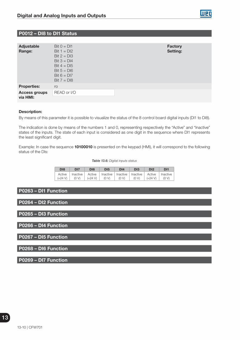
13
Digital and Analog Inputs and Outputs
13-10 | CFW701
P0012 – DI8 to DI1 Status
Adjustable Range:
Bit 0 = DI1Bit 1 = DI2Bit 2 = DI3Bit 3 = DI4Bit 4 = DI5Bit 5 = DI6Bit 6 = DI7Bit 7 = DI8
Factory Setting:
Properties: ro
Access groupsvia HMI:
READ or I/O
Description:
By means of this parameter it is possible to visualize the status of the 8 control board digital inputs (DI1 to DI8).
The indication is done by means of the numbers 1 and 0, representing respectively the “Active” and “Inactive” states of the inputs. The state of each input is considered as one digit in the sequence where DI1 represents the least significant digit.
Example: In case the sequence 10100010 is presented on the keypad (HMI), it will correspond to the following status of the DIs:
Table 13.6: Digital inputs status
DI8 DI7 DI6 DI5 DI4 DI3 DI2 DI1
Active(+24 V)
Inactive(0 V)
Active(+24 V)
Inactive(0 V)
Inactive(0 V)
Inactive(0 V)
Active(+24 V)
Inactive(0 V)
P0263 – DI1 Function
P0264 – DI2 Function
P0265 – DI3 Function
P0266 – DI4 Function
P0267 – DI5 Function
P0268 – DI6 Function
P0269 – DI7 Function
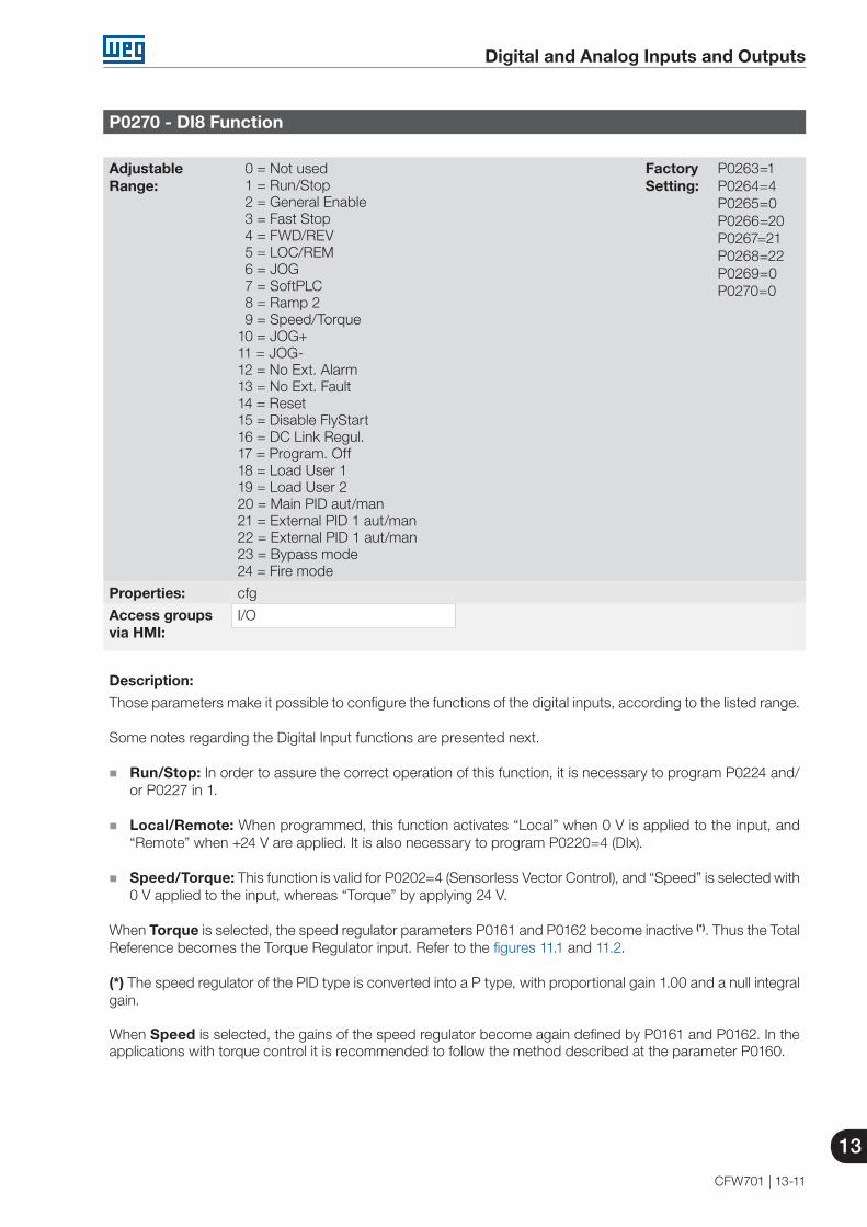
Digital and Analog Inputs and Outputs
13
CFW701 | 13-11
P0270 - DI8 Function
Adjustable Range:
0 = Not used1 = Run/Stop2 = General Enable3 = Fast Stop4 = FWD/REV5 = LOC/REM6 = JOG7 = SoftPLC8 = Ramp 29 = Speed/Torque
10 = JOG+11 = JOG-12 = No Ext. Alarm13 = No Ext. Fault14 = Reset15 = Disable FlyStart16 = DC Link Regul.17 = Program. Off18 = Load User 119 = Load User 220 = Main PID aut/man21 = External PID 1 aut/man22 = External PID 1 aut/man23 = Bypass mode24 = Fire mode
Factory Setting:
P0263=1P0264=4P0265=0P0266=20P0267=21P0268=22P0269=0P0270=0
Properties: cfg
Access groupsvia HMI:
I/O
Description:
Those parameters make it possible to configure the functions of the digital inputs, according to the listed range.
Some notes regarding the Digital Input functions are presented next.
Run/Stop: In order to assure the correct operation of this function, it is necessary to program P0224 and/or P0227 in 1.
Local/Remote: When programmed, this function activates “Local” when 0 V is applied to the input, and
“Remote” when +24 V are applied. It is also necessary to program P0220=4 (DIx).
Speed/Torque: This function is valid for P0202=4 (Sensorless Vector Control), and “Speed” is selected with 0 V applied to the input, whereas “Torque” by applying 24 V.
When Torque is selected, the speed regulator parameters P0161 and P0162 become inactive (*). Thus the Total Reference becomes the Torque Regulator input. Refer to the figures 11.1 and 11.2.
(*) The speed regulator of the PID type is converted into a P type, with proportional gain 1.00 and a null integral gain.
When Speed is selected, the gains of the speed regulator become again defined by P0161 and P0162. In the applications with torque control it is recommended to follow the method described at the parameter P0160.

13
Digital and Analog Inputs and Outputs
13-12 | CFW701
DC Link Regulation: It must be used when P0184=2. For more details, refer to this parameter description in item 11.8.7 - DC Link Regulator, of this manual.
JOG+ and JOG-: Those are functions valid only for P0202=5 or 4.
Disables Flying-Start: It is valid for P0202≠5. By applying +24 V to the digital input programmed for this purpose, the Flying-Start function is disabled. By applying 0 V, the Flying-Start function is enabled again, provided that P0320 be equal to 1 or 2. Refer to the section 12.5 - Flying Start/Ride-Through.
Load User 1: This function allows the selection of the user memory 1, in a similar process than P0204=7,
with the difference that the user memory is loaded from a transition of the DIx programmed for this function.
When the state of the DIx changes from low level to high level (transition from 0 V to 24 V), the user memory 1 is loaded, provided that the contents of the inverter actual parameters had been previously transferred to the parameter memory 1 (P0204=9).
Inverter Parameters
User 1
User 2P0204=10
P0204=9
P0263 to P0270 (DIx)=18
DIx=0 V
P0263 to P0270 (DIx)=19
DIx=24 V DIx=0 V
DIx=24 V
Figure 13.4: Details on the working of the Load User 1 or 2 function
Load User 2: This function allows the selection of the user memory 2, in a similar process than P0204=8, with the difference that the user memory is loaded from a transition of the DIx programmed for this function.
When the state of the DIx changes from low level to high level (transition from 0 V to 24 V), the user memory 2 is loaded, provided that the contents of the inverter actual parameters had been previously transferred to the parameter memory 2 (P0204=10).
NOTES!Make sure that when using those functions the parameter sets (user memory 1, 2) be totally compatible with the application (motors, Run/Stop commands, etc.).
It will not be possible to load the user memory with the inverter enabled.
If two parameter sets from different motors were saved in the user memories 1 and 2, the correct current values must be adjusted at the parameters P0156, P0157 and P0158 for each user memory.
Parametrization Blocking: When this function is programmed and the digital input is with +24 V, parameter changes will not be allowed, regardless of the values set at P0000 and P0200. When the DIx input is with 0 V, the parameter changes will be conditioned to the P0000 and P0200 settings.
No External Alarm: This function will indicate “External Alarm” (A090) on the keypad (HMI) display when
the programmed digital input is open (0 V). If +24 V is applied to the input, the alarm message will disappear automatically from the keypad (HMI) display. The motor keeps working normally, regardless of the state of that input.
Bypass mode: Signals the switch to bypass mode
Fire mode: Signals the switch to fire mode

Digital and Analog Inputs and Outputs
13
CFW701 | 13-13
Automatic / Manual for Main PID configures the input to select the operating mode of the Main PID Controller, being automatic with the application of 0 V, or manual with the application of 24 V. The parameter P1018 defines its functionality in the operation of the Main PID Controller.
Automatic / Manual for External PID 1 configures the input to select the operating mode of the External PID Controller 1, being automatic with the application of 0 V, or manual with the application of 24 V. The parameter P1065 defines its functionality in the operation of the External PID Controller 1.
Automatic / Manual for External PID 2 configures the input to select the operating mode of the External PID Controller 2, being automatic with the application of 0 V, or manual with the application of 24 V. The parameter P1085 defines its functionality in the operation of the External PID Controller 2.
NOTE!In options 20, 21 and 22, in case two or more digital inputs are selected for the same function, for instance, P0266=20 and P0267=20, only the digital input with higher priority will be valid, being DI1>DI2>DI3>DI4>DI5>DI6>DI7>DI8, that is, in this case the digital input DI4 will be the input used as automatic/manual of the Main PID Controller. Refer to chapter 19 – HVAC Functions, for further information.

13
Digital and Analog Inputs and Outputs
13-14 | CFW701
Figure 13.5 (a) to (g): Details on the operation of the digital input functions
Time
DIx
24 V
Motor speed Motor speed
Deceleration ramp
DIx Open
Time
Motor runs free (coasts)
Time
TimeTime 24 V
Open
24 V
Time
Time
Motor speed
DIx
Open
Open
24 V
Time
Time
24 V
Time
P0102
P0100
DIx -
Run/Stop
DIx - ramp 2
(e) RAMP 2
Open
Time
Time
Motor speed
24 V
DIx - Fast Stop
Motor decelerateswith ramp zero
Acceleration ramp Acceleration ramp
Motor speed
Open
Open
24 V
Time
Time
Motor speed
DIx
Forward
Reverse
(f) FAST STOP
(d) FWD/REV(c) NO EXTERNAL FAULT
(a) RUN/STOP (b) GENERAL ENABLE
Motor runs free (coasts)
P0103
P0101
Note: All the digital inputs programmed for General Enable, Fast Stop, Forward Run or Reverse Run must be in the ON state, so that the CFW701 operates as described above.
(g) LOAD USER VIA DIx
Time
Load user 1DIx Open
24 V
Note: All the digital inputs programmed for Run/Stop, Fast Stop, Forward Run or Reverse Run must be in the ON state, so that the CFW701 operates as described above.
24 V
Open
Load user 2

Digital and Analog Inputs and Outputs
13
CFW701 | 13-15
Figure 13.5 (h) to (j) (cont.): Details on the operation of the digital input functions
Time
Motor speed
24 V
24 V
Run/Stop
JOG Speed (P0122)
Deceleration ramp
24 V
DIx - JOG
General enable
Open
Open
Aceleration ramp
(h) JOG
With Fault
24 V
General enableRun/Stop
Time24 V
Time
Time
24 V
Without fault
Reset
DIx - Reset Open
Motor speed
Inverter status (*)
JOG+ (P0122), JOG- (P0123) Speed
Time
Time
Time
Time
Time
Time
(*) The condition that caused the error persists.
24 V
Open
DIx - JOG ±
(j) RESET
Run/Stop
General enable
(i) JOG + and JOG -
Open
Open Open

13
Digital and Analog Inputs and Outputs
13-16 | CFW701
13.1.4 Digital Outputs / Relays
The CFW701 has two digital output relays and 3 open collector outputs available in the control board as standard. The next parameters configure the functions related to those outputs.
P0013 – DO5 to DO1 Status
Adjustable Range:
Bit 0 = DO1Bit 1 = DO2Bit 2 = DO3Bit 3 = DO4Bit 4 = DO5
Factory Setting:
Properties: ro
Access groupsvia HMI:
READ or I/O
Description:
By means of this parameter it is possible to visualize the status of the control board 5 digital outputs (DO1 to DO5).
The indication is done by means of the numbers “1” and “0”, representing respectively the “Active” and “Inactive” states of the outputs. The state of each output is considered as one digit in the sequence where DO1 represents the least significant digit.
Example: In case the sequence 00010010 is presented on the keypad (HMI), it will correspond to the following status of the DOs:
Table 13.7: Digital outputs status
DO5 DO4 DO3 DO2 DO1
Active(+24 V)
Inactive(0 V)
Inactive(0 V)
Active(+24 V)
Inactive(0 V)
P0275 – DO1 Function (RL1)
P0276 – DO2 Function (RL2)
P0277 – DO3 Function
P0278 – DO4 Function
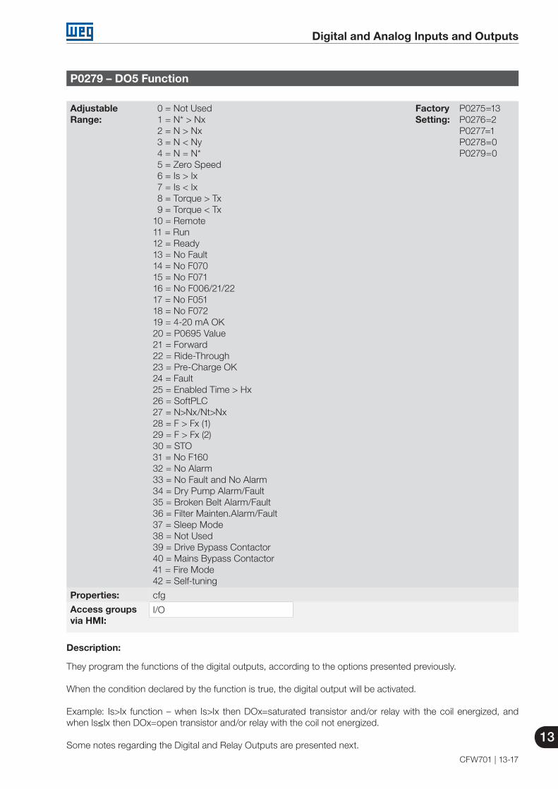
Digital and Analog Inputs and Outputs
13
CFW701 | 13-17
P0279 – DO5 Function
Adjustable Range:
0 = Not Used1 = N* > Nx2 = N > Nx3 = N < Ny4 = N = N*5 = Zero Speed6 = Is > Ix7 = Is < Ix8 = Torque > Tx9 = Torque < Tx
10 = Remote11 = Run12 = Ready13 = No Fault14 = No F07015 = No F07116 = No F006/21/2217 = No F05118 = No F07219 = 4-20 mA OK20 = P0695 Value21 = Forward22 = Ride-Through23 = Pre-Charge OK24 = Fault25 = Enabled Time > Hx26 = SoftPLC27 = N>Nx/Nt>Nx28 = F > Fx (1)29 = F > Fx (2)30 = STO31 = No F16032 = No Alarm33 = No Fault and No Alarm 34 = Dry Pump Alarm/Fault35 = Broken Belt Alarm/Fault36 = Filter Mainten.Alarm/Fault37 = Sleep Mode38 = Not Used39 = Drive Bypass Contactor 40 = Mains Bypass Contactor 41 = Fire Mode 42 = Self-tuning
Factory Setting:
P0275=13P0276=2P0277=1P0278=0P0279=0
Properties: cfg
Access groupsvia HMI:
I/O
Description:
They program the functions of the digital outputs, according to the options presented previously.
When the condition declared by the function is true, the digital output will be activated.
Example: Is>Ix function – when Is>Ix then DOx=saturated transistor and/or relay with the coil energized, and when Is≤Ix then DOx=open transistor and/or relay with the coil not energized.
Some notes regarding the Digital and Relay Outputs are presented next.

13
Digital and Analog Inputs and Outputs
13-18 | CFW701
Not Used: it means that the digital outputs will remain always in a resting state, i.e., DOx=open transistor and/or relay with the coil not energized.
Zero Speed: it means that the motor speed is below the value adjusted in P0291 (Zero Speed).
Torque > Tx and Torque < Tx: they are valid only for P0202=5 or 4 (Vector Control). In those functions “Torque” corresponds to the motor torque as indicated at parameter P0009.
Remote: it means that the inverter is operating in Remote situation.
Run: it corresponds to enabled inverter. In this moment the IGBTs are commutating, and the motor may be at any speed, including zero.
Ready: it corresponds to the inverter without fault and without undervoltage.
No Fault: it means that the inverter is not disabled by any type of fault.
No F070: it means that the inverter is not disabled by the F070 fault (Overcurrent or Short-circuit).
No F071: it means that the inverter is not disabled by the F071 fault (Output Overcurrent).
No F006+F021+F022: it means that the inverter is not disabled by the F006 fault (Input Voltage Imbalance or Phase Loss), neither by F021 (DC Link Undervoltage), nor by F022 (DC Link Overvoltage).
No F051: it means that the inverter is not disabled by the F051 fault (IGBT Overtemperature).
No F072: it means that the inverter is not disabled by the F072 fault (Motor Overload).
4 - 20 mA OK: it means that the current reference (4 to 20 mA) at the analog inputs AIx is inside the 4 to 20 mA range.
P0695 Value: it means that the state of the digital output will be controlled by P0695, which is written via the network. Refer to the CFW701 Serial communication manual for more details on this parameter.
Forward: it means that when the motor is rotating in the forward direction the DOx=saturated transistor and/or relay with the coil energized, and when the motor is rotating in the reverse direction, the DOx=open transistor and/or relay with the coil not energized.
Ride-Through: it means that the inverter is executing the Ride-Through function.
Pre-charge OK: it means that the DC Link voltage is above the pre-charge voltage level.
Fault: it means that the inverter is disabled by any type of fault.
N > Nx and Nt > Nx: (valid only for P0202=5 – Vector with Encoder) it means that both the conditions must be satisfied so that DOx=saturated transistor and/or relay with the coil energized. In other words, it is enough that the condition N>Nx be not satisfied (regardless of the Nt>Nx condition) so that DOx=open transistor and/or relay with the coil not energized.
SoftPLC: it means that the digital output state will be controlled by the programming done in the memory area reserved to the SoftPLC function. Refer to the SoftPLC manual for more details.
STO: it signalizes the STO state (Safety Stop active).
No F160: it signalizes that the inverter is not disabled by F160 fault (Safety Stop Relay).
No Alarm: it means that the inverter is not in the alarm condition.
No Fault and No Alarm: it means that the inverter is not disabled by any type of fault and it is not in alarm condition.

Digital and Analog Inputs and Outputs
13
CFW701 | 13-19
Dry Pump: it means that the dry pump condition was detected (A0766 / F0767).
Broken Belt: it means the condition that the broken belt condition was detected (A0768 / F0769).
Filter Change: it means that the condition to change the filter was detected (A0770 / F0771).
Sleep Mode: it means that the motor driven by the frequency inverter CFW701 is with the sleep mode active (A0764).
Drive Bypass Contactor: it means that the output is activating the drive bypass contactor, that is, the motor is being powered by the drive.
Mains Bypass Contactor: it means that the output is activating the mains bypass contactor, that is, the motor is being powered directly by the mains.
Fire Mode: it means that the CFW701 is operating in Fire Mode.
NOTE!Refer to chapter 19 - HVAC Functions, for further information on the options 34 to 41.
Definitions of the symbols used in the function:
N = P0002 (Motor Speed). N* = P0001 (Speed Reference).Nx = P0288 (Nx Speed) – It is a reference point of the speed selected by the user.Ny = P0289 (Ny Speed) – It is a reference point of the speed selected by the user.Ix = P0290 (Ix Current) – It is a reference point of the current selected by the user.Is = P0003 (Motor Current).Torque = P0009 (Motor Torque).Tx = P0293 (Tx Torque) – It is a reference point of the torque selected by the user.Nt = Total Reference (refer to the figure 13.7).Hx = P0294 (Hx Time).F = P0005 (Motor Frequency).Fx = P0281 (Fx Frequency) – It is a reference point of the motor frequency selected by the user.

13
Digital and Analog Inputs and Outputs
13-20 | CFW701
NN*
ON
OFF OFFRelay/Transistor
Time
(d) N = N*
N
Relay/Transistor OFF
ON
(b) N > Nx
OFF
Time
Nx (P0288)
P0287
P0287
(c) N < Ny
N
Time
ON
OFF
Ny (P0289)
Relay/Transistor ON
P0287
P0287
(a) N* > Nx
N*
Relay/Transistor OFF
ON
OFF
Nx (P0288)
Time
(g) Is < Ix
Is
Relay/ Transistor
ON
OFF
ON
Ix (P0290)
Time
ON
OFFOFFRelay/ Transistor
Motor Torque (P0009)
Tx (P0293)
Time
(h) Torque > Tx
(f) Is > Ix
ON
Relay/Transistor OFF
Is
OFF
Time
Ix (P0290)P0291
Relay/ Transistor
OFF OFFON
Speed
(e) N = 0 (Zero) Speed
Figure 13.6 (a) to (h): Details on the operation of the digital and relay output functions

Digital and Analog Inputs and Outputs
13
CFW701 | 13-21
Relay / TransistorON
No fault
OFF
Time
Fault
(j) No fault
Motor Torque (P0009)
Relay/Transistor
ONON
OFF
Tx (P0293)
Time
(i) Torque <Tx
Relay / TransistorOFF
ON
Fault
Time
Time
No fault
(k) Fault (l) 4-20 mA Reference OK
Relay / Transistor
ON ONOFF
Time
2 mAReference
(o) N > Nx and Nt > Nx
Nt N
Relay/Transistor OFF
ON
OFF
Time
Nx (P0288)
OFFOFF
Enable Hours.(P0043)
6553 h
0
N
Relay/Transistor
ON
Hx (P0294)
Time
(n) Enabled Time > Hx
Relay / Transistor
ON ONOFF
Time
Pre-charge Level
DC Link
(m) Pre-Charge Ok
(p) F > Fx (1)
P0281 + P0282
P0281 - P0282Fx (P0281)
N
OFF
ON
Relay
Figure 13.6 (i) to (p) (cont.): Details on the operation of the digital and relay output functions

13
Digital and Analog Inputs and Outputs
13-22 | CFW701
(q) F > Fx (2)
P0281 - P0282Fx (P0281)
N
OFF
ON
Relay /Transistor OFF
(r) No Alarm
Relay / TransistorON
No Alarm
OFF
Time
Alarm
Figure 13.6 (q) and (r) (cont.): Details on the operation of the digital and relay output functions
P0281 – Fx Frequency
Adjustable Range:
0.0 to 300.0 Hz Factory Setting:
4.0 Hz
Properties:
Access groupsvia HMI:
Description:
It is used in the digital output and relay functions:
F > Fx(1) and F > Fx (2)
P0282 – Fx Hysteresis
Adjustable Range:
0.0 to 15.0 Hz Factory Setting:
2.0 Hz
Properties:
Access groupsvia HMI:
Description:
It is used in the digital output and relay functions:
F > Fx(1) and F > Fx (2)

Digital and Analog Inputs and Outputs
13
CFW701 | 13-23
P0287 – Nx/Ny Hysteresis
Adjustable Range:
0 to 900 rpm Factory Setting:
18 rpm(15 rpm)
Properties:
Access groupsvia HMI:
Description:
It is used in the N > Nx and N < Ny functions of the digital and relay outputs.
P0288 – Nx Speed
Adjustable Range:
0 to 18000 rpm Factory Setting:
120 rpm (100 rpm)
P0289 – Ny Speed
Adjustable Range:
0 to 18000 rpm Factory Setting:
1800 rpm(1500 rpm)
Properties:
Access groupsvia HMI:
Description:
They are used in the N* > Nx, N > Nx, and N < Ny functions of the digital and relay outputs.
P0290 – Ix Current
Adjustable Range:
0 to 2 x Inom-ND Factory Setting:
1.0 x Inom-ND
Properties:
Access groupsvia HMI:
Description:
It is used in the Is > Ix and Is < Ix functions of the digital and relay outputs.

13
Digital and Analog Inputs and Outputs
13-24 | CFW701
P0291 – Zero Speed
Adjustable Range:
0 to 18000 rpm Factory Setting:
18 rpm(15 rpm)
Properties:
Access groupsvia HMI:
Description:
It specifies the value in rpm below which the actual speed will be considered null for the Zero Speed Disable function.
This parameter is also used by the functions of the digital and relay outputs.
P0292 – N = N* Band
Adjustable Range:
0 to 18000 rpm Factory Setting:
18 rpm(15 rpm)
Properties:
Access groupsvia HMI:
Description:
It is used in the N = N* function of the digital and relay outputs.
P0293 – Tx Torque
Adjustable Range:
0 to 200 % Factory Setting:
100 %
Properties:
Access groupsvia HMI:
Description:
It is used in the Torque > Tx and Torque < Tx functions of the digital and relay outputs.
In those functions the motor torque indicated in P0009 is compared with the value adjusted in P0293.
The setting of this parameter is expressed as a percentage of the motor rated current (P0401=100 %).
P0294 – Hx Time
Adjustable Range:
0 to 6553 h Factory Setting:
4320 h
Properties:
Access groupsvia HMI:
Description:
It is used in the Enabled Hours > Hx function of the digital and relay outputs.

Digital and Analog Inputs and Outputs
13
CFW701 | 13-25
13.2 LOCAL AND REMOTE COMMAND
In those parameter groups one can configure the origin of the main inverter commands when in the LOCAL or in the REMOTE situation, as the Speed Reference, Speed Direction, Run/Stop and JOG.
P0220 – LOCAL/REMOTE Selection Source
Adjustable Range:
0 = Always Local1 = Always Remote2 = Local/Remote Key Local3 = Local/Remote Key Remote4 = DIx5 = Serial Local6 = Serial Remote7 = SoftPLC Local8 = SoftPLC Remote
Factory Setting:
2
Properties: cfg
Access groupsvia HMI:
I/O
Description:
It defines the origin of the command that will select between the LOCAL situation and the REMOTE situation, where:
LOCAL: Means Local Default situation. REMOTE: Means Remote Default situation. DIx: Refer to item 13.1.3 - Digital Inputs.
P0221 – Speed Reference Selection – LOCAL Situation
P0222 – Speed Reference Selection – REMOTE Situation
Adjustable Range:
0 = HMI1 = AI12 = AI23 = AI34 = AI1+AI2 > 0 (Sum AIs>0)5 = AI1+AI2 (Sum AIs)6 = Serial7 = SoftPLC
Factory Setting:
P0221=0P0222=1
Properties: cfg
Access groupsvia HMI:
I/O
Description:
They define the origin of the Speed Reference in the LOCAL situation and in the REMOTE situation.
Some notes about the options for those parameters:
The AIx’ designation refers to the analog signal obtained after the addition of the AIx input to the offset and its multiplication by the applied gain (refer to item 13.1.1 - Analog Inputs).
The value of the reference adjusted with the and is contained in the parameter P0121.
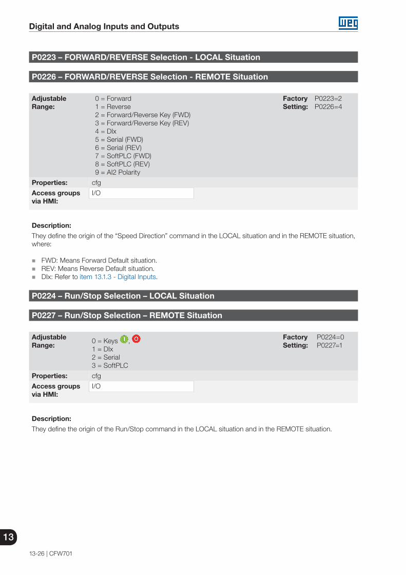
13
Digital and Analog Inputs and Outputs
13-26 | CFW701
P0223 – FORWARD/REVERSE Selection - LOCAL Situation
P0226 – FORWARD/REVERSE Selection - REMOTE Situation
Adjustable Range:
0 = Forward 1 = Reverse 2 = Forward/Reverse Key (FWD)3 = Forward/Reverse Key (REV)4 = DIx5 = Serial (FWD)6 = Serial (REV)7 = SoftPLC (FWD)8 = SoftPLC (REV)9 = AI2 Polarity
Factory Setting:
P0223=2P0226=4
Properties: cfg
Access groupsvia HMI:
I/O
Description:
They define the origin of the “Speed Direction” command in the LOCAL situation and in the REMOTE situation, where:
FWD: Means Forward Default situation. REV: Means Reverse Default situation. DIx: Refer to item 13.1.3 - Digital Inputs.
P0224 – Run/Stop Selection – LOCAL Situation
P0227 – Run/Stop Selection – REMOTE Situation
Adjustable Range:
0 = Keys , 1 = DIx2 = Serial3 = SoftPLC
Factory Setting:
P0224=0P0227=1
Properties: cfg
Access groupsvia HMI:
I/O
Description:
They define the origin of the Run/Stop command in the LOCAL situation and in the REMOTE situation.

Digital and Analog Inputs and Outputs
13
CFW701 | 13-27
P0225 – JOG Selection – LOCAL Situation
P0228 – JOG Selection – REMOTE Situation
Adjustable Range:
0 = Inactive1 = JOG Key 2 = DIx3 = Serial4 = SoftPLC
Factory Setting:
P0225=1P0228=2
Properties: cfg
Access groupsvia HMI:
I/O
Description:
They define the origin of the JOG command in the LOCAL situation and in the REMOTE situation.
P0229 – Stop Mode Selection
Adjustable Range:
0 = Ramp to Stop1 = Coast to Stop2 = Fast Stop
Factory Setting:
0
Properties: cfg
Access groupsvia HMI:
Description:
It defines the motor stop mode when the inverter receives the “Stop” command. The table 13.8 describes the options of this parameter.
Table 13.8: Stop mode selection
P0229 Description0 = Ramp to Stop The inverter will apply the ramp programmed P0101 and/or P0103.1 = Coast to Stop The motor will run free until stopping.
2 = Fast StopThe inverter will apply a null ramp (time = 0.0 second), in order to stop the motor in the shortest possible time.
NOTE!When the control modes V/f or VVW are selected, the use of the option 2 (Fast Stop) is not recommended.
NOTE!When the Coast to Stop mode, is programmed and the Flying-Start function is not enabled, then start the motor again only if it is standing still.

13
Digital and Analog Inputs and Outputs
13-28 | CFW701
AI2
AI1
AI3
P02
39
P02
34P
0237
P02
32
P02
42P
0244
P00
19
P00
18
P00
20
P02
36 =
1 -
Ref
. aft
er R
amp
(P02
36 =
No
Ram
p R
efer
ence
) (*)
P02
31 =
1 -
Ref
. aft
er R
amp
(P02
31 =
No
Ram
p R
efer
ence
) (*)
P02
44 =
1 -
Ref
. aft
er R
amp
(P02
41 =
No
Ram
p R
efer
ence
) (*)
JOG
+ (*
)
Com
man
d vi
a di
gita
l inp
uts
(DIx
)
JOG
- (*
)
2a
JOG
-1
FWD
/RE
V
(Spe
ed d
irect
ion)
Run
/Sto
p
JOGR
efer
ence
Lim
its
P01
34
P01
33
P01
33
P01
34
Tota
l R
efer
ence
++
+-
Com
man
ds
and
Ref
eren
ce.
Ref
er to
the
figur
e 13
.8.
P01
22
OFF
SE
T:P
0163
- L
OC
P01
64 -
RE
M
P00
01
P01
34 =
Max
imum
R
efer
ence
P01
33 =
Min
imum
R
efer
ence
P01
23
P01
22
P01
02-A
ccel
erat
ion
P01
03-D
ecel
erat
ion
Acc
eler
atio
n/D
ecel
erat
ion
Tim
e 2
P01
00-A
ccel
erat
ion
P01
01-D
ecel
erat
ion
Fast
Sto
p
Acc
eler
atio
n/D
ecel
erat
ion
Tim
e
(*) Valid only for P0202=4.
Ref
eren
ce
Figure 13.7: Speed Reference block diagram

Digital and Analog Inputs and Outputs
13
CFW701 | 13-29
Local
Reference (P0221)
Local
Reference
Remote
Reference
Local
Commands
Remote
Commands
(P0220)Local/remote Selection
Reference
CommandsCommands
Reference
Forward/reverse(P0223)
Jog (P0225)
Run/stop (P0224)
Remote
Reference (P0222)
Forward/reverse(P0226)
Jog (P0228)
Run/stop (P0227)
Figure 13.8: Local/Remote situation block diagram

13
Digital and Analog Inputs and Outputs
13-30 | CFW701

Dynamic Braking
14
CFW701 | 14-1
14 DYNAMIC BRAKING
The braking torque that can be obtained through the application of frequency inverters without dynamic braking resistors varies from 10 % to 35 % of the motor rated torque.
In order to obtain higher braking torques, resistors for dynamic braking are used. In this case the regenerated energy is dissipated on the resistor mounted externally to the inverter.
This type of braking is used in the cases when short deceleration times are wished or when high inertia loads are driven.
For the vector control mode there is the possibility of the use of the “Optimal Braking”, eliminating in many cases the need of the dynamic braking.
The Dynamic Braking function can only be used if a braking resistor has been connected to the CFW701, and if the parameters related to it have been adjusted properly.
See next the description of the parameters in order to know how to program each one.
P0153 – Dynamic Braking Level
Adjustable Range:
339 to 400 V585 to 800 V585 to 800 V585 to 800 V585 to 800 V809 to 1000 V809 to 1000 V809 to 1000 V
Factory Setting:
P0296=0: 375 VP0296=1: 618 VP0296=2: 675 VP0296=3: 748 VP0296=4: 780 VP0296=5: 893 VP0296=6: 972 VP0296=7: 972 V
Properties:
Access groupsvia HMI:
Description:
The parameter P0153 defines the voltage level for the braking IGBT actuation, and it must be compatible with the power supply voltage.
If P0153 is adjusted at a level very close to the overvoltage (F022) actuation level, the fault may occur before the braking resistor is able to dissipate the regenerated energy.
The next table presents the overvoltage trip level.
Table 14.1: Overvoltage (F022) trip levels
Inverter Vnom P0296 F022
220/230 V 0 > 400 V380 V 1
> 800 V400/415 V 2440/460 V 3
480 V 4500/525 V 5
> 1000 V 550/575 V 6 600 V 7

14
Dynamic Braking
14-2 | CFW701
F022 - Overvoltage
Dynamic braking actuation
Time
TimeBraking Resistor Voltage (DB)
UdUd
P0153Rated Ud
DC Link Voltage (Ud) (P0004)
Figure 14.1: Dynamic Braking actuation curve
Steps to enable the dynamic braking:
Connect the braking resistor. Refer to item 3.2.3.2 - Dynamic Braking (standard built-in for sizes A, B, C and D and optional built-in for size E - CFW701...DB...), of the user's manual.
Set P0151 at the maximum value: 400 V (P0296=0), 800 V (P0296=1, 2, 3 or 4) or 1000 V (P0296=5, 6 or 7),
according to the case, in order to prevent the activation of the DC voltage regulation before the dynamic braking.

Faults and Alarms
15
CFW701 | 15-1
15 FAULTS AND ALARMS
The troubleshooting structure of the inverter is based on the indication of faults and alarms.
In a fault event the IGBTs firing pulses are disabled and the motor coasts to stop.
ATTENTION!If the Fire Mode function is active, most failures will be detected, but ignored by CFW701, i.e., will not block the IGBTs. If the motor was spinning, will continue spinning. Some faults as DC Voltage (F022), over current / short circuit (F070), Safety Stop(F160) will not be ignored, but may be self-reset infinitely (select this option in parameter P0582). For more information see Chapter 19 - HVAC Functions, on the section Fire Mode.
The alarm works as a warning to the user that critical operation conditions are occurring and a fault may occur if the situation does not change.
Refer to the CFW701 user's manual chapter 6 - Troubleshooting and Maintenance, and the section Quick Parameter Reference, Faults and Alarms of this manual to obtain more information regarding the Faults and Alarms.
15.1 MOTOR OVERLOAD PROTECTION
The Motor Overload protection is based on the use of curves that simulate the heating and cooling of the motor in overload events, according to IEC 60947-4-2 and UL 508C standards. The fault and alarm codes for the motor overload protection are F072 and A046, respectively.
The motor overload is given in function of the reference value In x SF (motor rated current multiplied by the service factor), which is the maximum value at which the protection must not actuate because the motor is able to operate indefinitely with this current value without suffering damages.
However, for that protection to act in an appropriate manner, the thermal image of the motor, which corresponds to the heating up and cooling down times of the motor, is estimated.
The thermal image, in its turn, depends on the motor thermal constant, which is estimated based on the motor power and number of poles.
The thermal image is important to allow that a derating in the fault actuation time be given, so that shorter actuation times be obtained when the motor is hot.
This function applies a derating in the fault actuation time depending on the output frequency supplied to the motor, because for the self-ventilated ones there will be less ventilation on the frame at lower speeds, and the motor will be subject to more heating. Thus, it becomes necessary to reduce the fault actuation time in order to prevent the motor from burning.
In order to assure more protection in case of restart, this function keeps the information regarding the motor thermal image in the CFW701 nonvolatile memory. Therefore, after the inverter restart, the function will use the value saved in the thermal memory to perform a new overload evaluation.
The parameter P0348 configures the desired protection level for the motor overload function. The possible options are: Fault and Alarm, only Fault, only Alarm, and disabled motor overload protection. The actuation level for the motor overload alarm (A046) is adjusted via P0349.
In order to get more information, refer to parameters P0156, P0159, P0348 and P0349 in the section 15.3 - Protections.
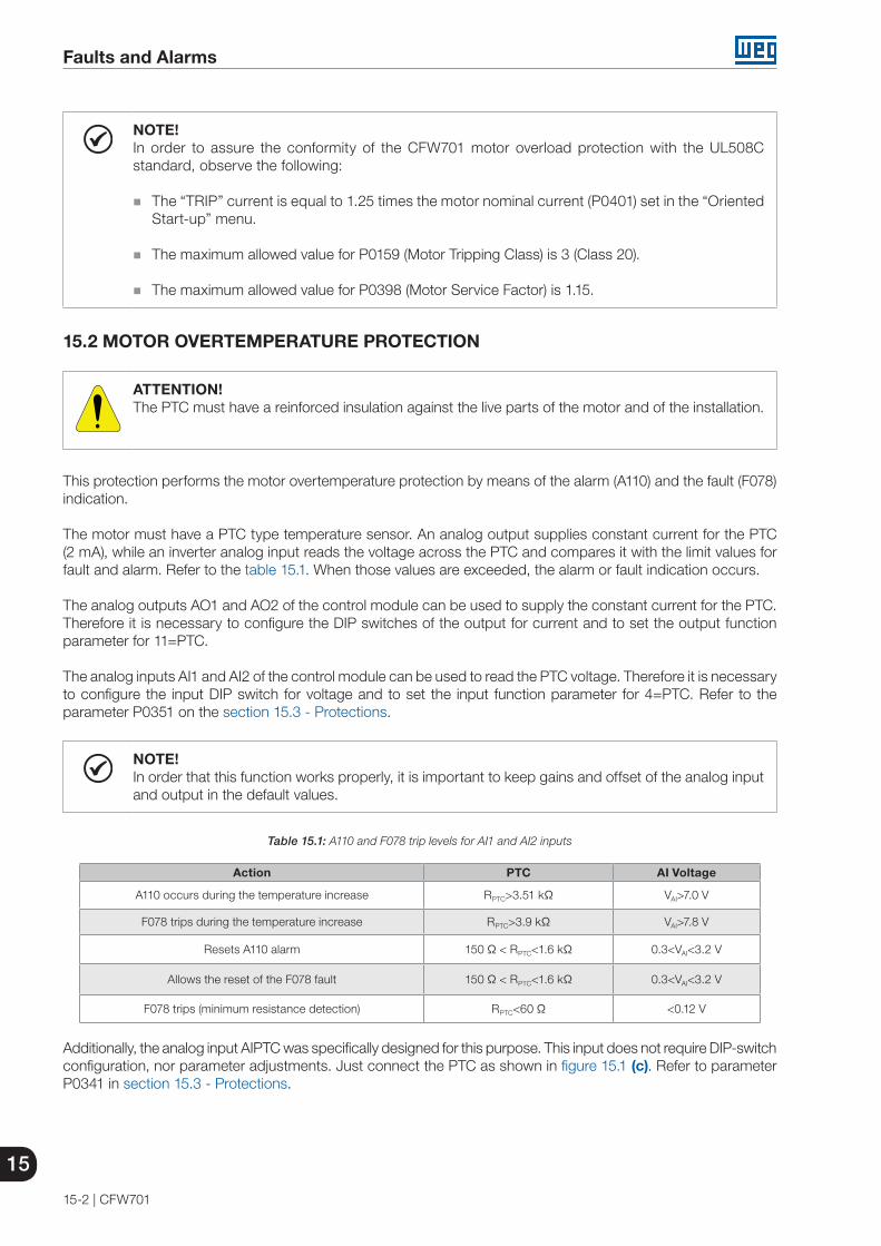
15
Faults and Alarms
15-2 | CFW701
NOTE!In order to assure the conformity of the CFW701 motor overload protection with the UL508C standard, observe the following:
The “TRIP” current is equal to 1.25 times the motor nominal current (P0401) set in the “Oriented Start-up” menu.
The maximum allowed value for P0159 (Motor Tripping Class) is 3 (Class 20).
The maximum allowed value for P0398 (Motor Service Factor) is 1.15.
15.2 MOTOR OVERTEMPERATURE PROTECTION
ATTENTION!The PTC must have a reinforced insulation against the live parts of the motor and of the installation.
This protection performs the motor overtemperature protection by means of the alarm (A110) and the fault (F078) indication.
The motor must have a PTC type temperature sensor. An analog output supplies constant current for the PTC (2 mA), while an inverter analog input reads the voltage across the PTC and compares it with the limit values for fault and alarm. Refer to the table 15.1. When those values are exceeded, the alarm or fault indication occurs.
The analog outputs AO1 and AO2 of the control module can be used to supply the constant current for the PTC. Therefore it is necessary to configure the DIP switches of the output for current and to set the output function parameter for 11=PTC.
The analog inputs AI1 and AI2 of the control module can be used to read the PTC voltage. Therefore it is necessary to configure the input DIP switch for voltage and to set the input function parameter for 4=PTC. Refer to the parameter P0351 on the section 15.3 - Protections.
NOTE!In order that this function works properly, it is important to keep gains and offset of the analog input and output in the default values.
Table 15.1: A110 and F078 trip levels for AI1 and AI2 inputs
Action PTC AI Voltage
A110 occurs during the temperature increase RPTC>3.51 kΩ VAI>7.0 V
F078 trips during the temperature increase RPTC>3.9 kΩ VAI>7.8 V
Resets A110 alarm 150 Ω < RPTC<1.6 kΩ 0.3<VAI<3.2 V
Allows the reset of the F078 fault 150 Ω < RPTC<1.6 kΩ 0.3<VAI<3.2 V
F078 trips (minimum resistance detection) RPTC<60 Ω <0.12 V
Additionally, the analog input AIPTC was specifically designed for this purpose. This input does not require DIP-switch configuration, nor parameter adjustments. Just connect the PTC as shown in figure 15.1 (c). Refer to parameter P0341 in section 15.3 - Protections.

Faults and Alarms
15
CFW701 | 15-3
Table 15.2: A110 and F078 trip levels for AIPTC input
Action PTC AI Voltage
A110 occurs during the temperature increase RPTC > 3,51 kΩ VAI > 2,3 V
F078 trips during the temperature increase RPTC > 3,9 kΩ VAI > 2,5 V
Resets A110 alarm 150 Ω < RPTC < 1,6 kΩ 0,18 < VAI < 1,4 V
Allows reset of the F078 fault 150 Ω < RPTC < 1,6 kΩ 0,18 < VAI < 1,4 V
F078 trips (minimum resistance detection) RPTC < 60 Ω < 0,07 V
PTC
XC1:22
23
28
27
AI1
AO1
CC701
Program P0231 = 4;Set S1.4 = OFF (0 to 10 V).
Program P0251 = 11;Set S1.1 = OFF (4 to 20 mA, 0 to 20 mA).
(a) AO1, AI1
Program P0236 = 4;Set S1.3 = OFF (0 to 10 V).
Program P0254 = 11;Set S1.2 = OFF (4 to 20 mA, 0 to 20 mA).
PTC
25
26
30
29
AI2
AO2
(b) AO2, AI2
PTC
XC1:2
3
AIPTC
CC701
(c) AIPTC
Figure 15.1 (a) to (c): PTC connection examples
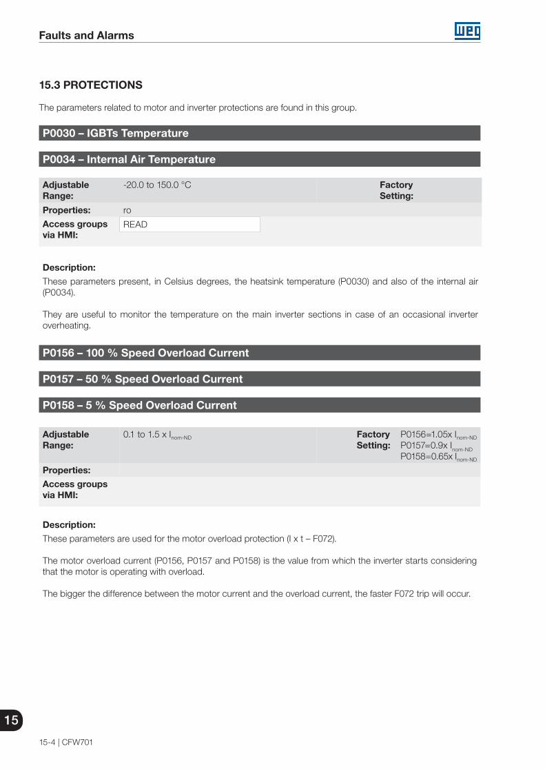
15
Faults and Alarms
15-4 | CFW701
15.3 PROTECTIONS
The parameters related to motor and inverter protections are found in this group.
P0030 – IGBTs Temperature
P0034 – Internal Air Temperature
Adjustable Range:
-20.0 to 150.0 °C Factory Setting:
Properties: ro
Access groupsvia HMI:
READ
Description:
These parameters present, in Celsius degrees, the heatsink temperature (P0030) and also of the internal air (P0034).
They are useful to monitor the temperature on the main inverter sections in case of an occasional inverter overheating.
P0156 – 100 % Speed Overload Current
P0157 – 50 % Speed Overload Current
P0158 – 5 % Speed Overload Current
Adjustable Range:
0.1 to 1.5 x Inom-ND Factory Setting:
P0156=1.05x Inom-ND
P0157=0.9x Inom-ND
P0158=0.65x Inom-ND
Properties:
Access groupsvia HMI:
Description:
These parameters are used for the motor overload protection (I x t – F072).
The motor overload current (P0156, P0157 and P0158) is the value from which the inverter starts considering that the motor is operating with overload.
The bigger the difference between the motor current and the overload current, the faster F072 trip will occur.
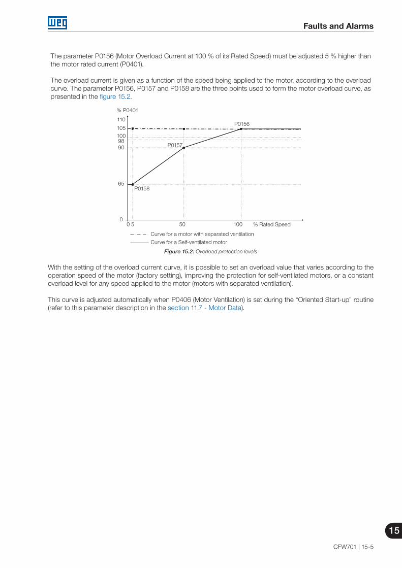
Faults and Alarms
15
CFW701 | 15-5
The parameter P0156 (Motor Overload Current at 100 % of its Rated Speed) must be adjusted 5 % higher than the motor rated current (P0401).
The overload current is given as a function of the speed being applied to the motor, according to the overload curve. The parameter P0156, P0157 and P0158 are the three points used to form the motor overload curve, as presented in the figure 15.2.
% Rated Speed
% P0401
P0156
0 5 50 100
110
1051009890
65
0
P0157
Curve for a motor with separated ventilation
Curve for a Self-ventilated motor
P0158
Figure 15.2: Overload protection levels
With the setting of the overload current curve, it is possible to set an overload value that varies according to the operation speed of the motor (factory setting), improving the protection for self-ventilated motors, or a constant overload level for any speed applied to the motor (motors with separated ventilation).
This curve is adjusted automatically when P0406 (Motor Ventilation) is set during the “Oriented Start-up” routine (refer to this parameter description in the section 11.7 - Motor Data).

15
Faults and Alarms
15-6 | CFW701
P0159 – Motor Tripping Class
Adjustable Range:
0 = Class 51 = Class 102 = Class 153 = Class 204 = Class 255 = Class 306 = Class 357 = Class 408 = Class 45
Factory Setting:
1
Properties: cfg
Access groupsvia HMI:
Description:
This parameter sets the motor thermal class, and the time for the correct actuation of the F072 fault depends on it. The higher the thermal class, the longer the fault actuation time will be.
ATTENTION!The incorrect selection of the thermal class may cause the burning of the motor.
ATTENTION!In order the CFW701 motor overload protection is in accordance with UL508C, the thermal class should be ≤20 (P0159 ≤ 3).
The necessary data for choosing the thermal class are the following:
Motor rated current (In). Blocked rotor current (Ip). Blocked rotor time (TRB)(*). Service factor (SF).
(*) It must be verified if the given blocked rotor time is for hot or cold motor, so that the correspondent thermal class curves be used.
With those values, the overload current and the overload time must be calculated using the following equations:
Overload Current = Ip x 100 (%)
In x FS
Overload Time = TBR (s)
These equations provide the limit conditions for the error actuation, i.e., the motor cannot work with a longer fault actuation time than this one, because of burning risk. Thus, a thermal class immediately inferior must be chosen so that the motor protection is assured.

Faults and Alarms
15
CFW701 | 15-7
Example: For a motor with the following characteristics,
In = 10,8 ATRB = 4 s (hot motor blocked rotor time)Ip / In = 7,8 ⇒ Ip = 7,8 x 10,8 A = 84,2 AFS = 1,15
One gets,
Overload Current = Ip =
84,2 x 100 = 678 % In x FS 10,8 x 1,15
Overload Time = TRB = 4 s
After this, it is only necessary to plot the calculated values on the motor overload graph (figures 15.3 (a) or 15.3 (b)), and to select the thermal class curve immediately below the calculated point.
Class 45Class 40Class 35Class 30Class 25Class 20Class 15
Class 10
Class 5
Current x In for F.S = 1.00
0 1
1x
1
10
100
1000
10000
100000
2x 3x 4x 5x 6x 7x 8x 9x 10x
2 3 4 5 6 7 9 108Current x In for F.S. = 1.15
Figure 15.3 (a): Cold motor overload curves for loads of the HD and ND types
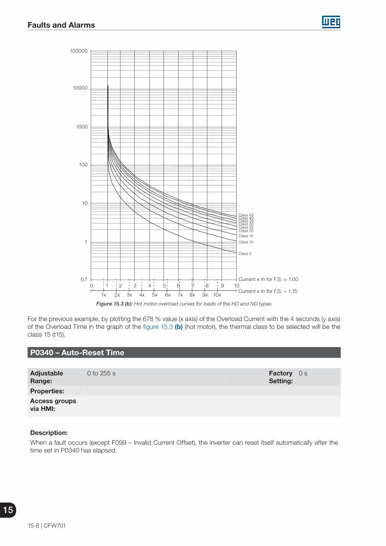
15
Faults and Alarms
15-8 | CFW701
Class 45Class 40Class 35Class 30Class 25Class 20Class 15
Class 10
Class 5
0 1
1x
0,1
1
100
10
1000
10000
100000
2x 3x 4x 5x 6x 7x 8x 9x 10x
2 3 4 5 6 7 9 108Current x In for F.S. = 1.15
Current x In for F.S. = 1.00
Figure 15.3 (b): Hot motor overload curves for loads of the HD and ND types
For the previous example, by plotting the 678 % value (x axis) of the Overload Current with the 4 seconds (y axis) of the Overload Time in the graph of the figure 15.3 (b) (hot motor), the thermal class to be selected will be the class 15 (t15).
P0340 – Auto-Reset Time
Adjustable Range:
0 to 255 s Factory Setting:
0 s
Properties:
Access groupsvia HMI:
Description:
When a fault occurs (except F099 – Invalid Current Offset), the inverter can reset itself automatically after the time set in P0340 has elapsed.
Faults and Alarms
15
CFW701 | 15-9
ATTENTION!In case the Fire Mode function is active and the DC Overvoltage (F022), Overcurrent/Short Circuit (F070) or Safety Stop (F160) faults are detected, the value set in P0340 may be ignored and those faults may be self-reset infinitely (select this option in parameter P0582). For further information, refer to “operation in Fire Mode” in Chapter 19 - HVAC Functions.
NOTE!The faults F051, F078 and F156 allow a conditional Reset, i.e., the Reset will only occur if the temperature gets back to the normal operation range.
If after Auto-Reset, the same fault is repeated three times consecutively, the Auto-Reset function will be disabled. A fault is considered consecutive if it happens again within 30 seconds after the Auto-Reset.
Therefore, if a fault occurs four consecutive times, the inverter will remain disabled (general disable) and the fault will remain being indicated.
If P0340 ≤ 2, auto-reset will not occur.
P0341 – AIPTC Configuration
Adjustable Range:
0 = Off1 = Fault/Alarm 2 = Fault3 = Alarm
Factory Setting:
0
Properties: cfg
Access groupsvia HMI:
Description:
This parameter is useful when the motor is equipped with PTC type temperature sensors, allowing the configuration of the protection level for the motor over temperature function. The details on the actuation of the available options are in the table 15.3. Refer also to the section 15.2 - Motor Overtemperature Protection.
Table 15.3: Actions for the parameters P0341 options
P0341 Action
0 = Off The over temperature protection is disabled. Faults or alarms for the motor operation in the over temperature condition will not be generated.
1 = Fault / Alarm The inverter will show an alarm (A110) and will generate a fault (F078) when the motor reaches the over temperature actuation values. Once a fault is generated, the inverter will be disabled.
2 = Fault Only the fault (F078) will be generated when the motor reaches the over temperature protection trip level, and the inverter will be disabled.
3 = Alarm Only the alarm (A110) will be generated when the motor reaches the protection actuation level, and the inverter remains operating.

15
Faults and Alarms
15-10 | CFW701
P0343 – Ground Fault Configuration
Adjustable Range:
0 = Off1 = On
Factory Setting:
1
Properties: cfg
Access groupsvia HMI:
Description:
This parameter enables the Ground Fault Detection, which will be responsible for the F074 (Ground Fault) actuation.
Thus if wished, it is possible to inhibit the Ground Fault (F074) occurrence by setting P0343=Off.
P0348 – Motor Overload Configuration
Adjustable Range:
0 = Off1 = Fault/Alarm2 = Fault3 = Alarm
Factory Setting:
1
Properties: cfg
Access groupsvia HMI:
Description:
This parameter allows the desired protection level for the motor overload function to be configured. Refer to the table below for details on the actuation of each one of the available options.
Table 15.4: Actions for the parameter P0348 options
P0348 Action
0 = OffThe overload protection is disabled. Faults or alarms will not be generated for the motor operation in overload conditions.
1 = Fault/AlarmThe inverter will display an alarm (A046) when the motor overload reaches the level programmed in P0349, and will generate a fault (F072) when the motor overload reaches the overload protection tripping level.
2 = FaultOnly the fault (F072) will be generated when the motor overload reaches the overload protection trip level, and the inverter will be disabled.
3 = AlarmOnly the alarm (A046) is generated when the motor overload reaches the value programmed in P0349 and the inverter continues operating.
The trip level of the overload protection is calculated internally by the CFW701, taking into account the motor current, its thermal class and its service factor. Refer to the parameter P0159 in this section.
Faults and Alarms
15
CFW701 | 15-11
P0349 – I x t Alarm Level
Adjustable Range:
70 to 100 % Factory Setting:
85 %
Properties: cfg
Access groupsvia HMI:
Description:
This parameter defines the level for the motor overload protection alarm actuation (A046), it is expressed as a percentage of the trip level of the overload integrator.
It will only be effective if P0348 is programmed in 1 (Fault/Alarm) or 3 (Alarm).
P0350 – IGBT Overload Configuration
Adjustable Range:
0 = Fault is active, with switching frequency reduction1 = Fault and alarm are active, with switching frequency
reduction2 = Fault is active, without switching frequency reduction3 = Fault and alarm are active, without switching frequency
reduction
Factory Setting:
1
Properties: cfg
Access groupsvia HMI:
Description:
The inverter overload function operates separately from the motor overload protection, and it has the purpose of protecting the IGBTs and rectifiers in case of overload, avoiding that damage due to overtemperature at their junctions occurs.
Thus, the parameter P0350 allows configuring the desired protection level for this function, even with the automatic reduction of the switching frequency, in order to avoid the fault occurrence. The next table describes each of the available options.
Table 15.5: Actions for the parameter P0350 options
P0350 Action
0It enables F048 – IGBT Overload Fault. In order to avoid the occurrence of the fault, the switching frequency is reduced automatically to 2.5 kHz. (*)
1It enables the fault F048 and the alarm A047 – IGBT Overload Alarm. In order to avoid the occurrence of the fault, the switching frequency is reduced automatically to 2.5 kHz. (*)
2 It enables F048. Without the reduction of the switching frequency.
3 It enables the alarm A047 and the fault F048. Without the reduction of the switching frequency.
(*) It reduces the switching frequency when: The output current exceeds 1.5 x Inom-HD (1.1 x Inom-ND ); or The temperature at the IGBT case is less than 10 °C from the maximum temperature; and P0297=2 (5 kHz).

15
Faults and Alarms
15-12 | CFW701
P0351 – Motor Overtemperature Configuration
Adjustable Range:
0 = Off1 = Fault/Alarm2 = Fault3 = Alarm
Factory Setting:
1
Properties: cfg
Access groupsvia HMI:
Description:
This parameter is useful when the motor is equipped with PTC type temperature sensors, allowing the configuration of the protection level for the motor overtemperature function. The details on the actuation of the available options are in the table 15.6. Refer also to the section 15.2 - Motor Overtemperature Protection.
Table 15.6: Actions for the parameter P0351 options
P0351 Action
0 = OffThe overtemperature protection is disabled. Faults or alarms for the motor operation in the overtemperature condition will not be generated.
1 = Fault / AlarmThe inverter will show an alarm (A110) and will generate a fault (F078) when the motor reaches the overtemperature actuation values. Once a fault is generated, the inverter will be disabled.
2 = FaultOnly the fault (F078) will be generated when the motor reaches the overtemperature protection trip level, and the inverter will be disabled.
3 = AlarmOnly the alarm (A110) will be generated when the motor reaches the protection actuation level, and the inverter remains operating.
P0352 – Fan Control Configuration
Adjustable Range:
0 = Heatsink fan and internal fan are OFF1 = Heatsink fan and internal fan are ON2 = Heatsink fan and internal fan are controlled via software3 = Heatsink fan is controlled via software and internal fan is OFF4 = Heatsink fan is controlled via software and internal fan is ON5 = Heatsink fan is ON and internal fan is OFF6 = Heatsink fan is ON and internal fan is controlled via software7 = Heatsink fan is OFF and internal fan is ON8 = Heatsink fan is OFF and internal fan is controlled via software
Factory Setting:
2
Properties: cfg
Access groupsvia HMI:
Description:
The CFW701 is equipped with two fans: an internal fan and a heatsink fan, and the activation of both will be controlled via software by means of the inverter programming.

Faults and Alarms
15
CFW701 | 15-13
The options available for the setting of this parameter are the following:
Table 15.7: Options of the parameter P0352
P0352 Action
0 = HS-OFF, Int-OFFHeatsink fan is always OFF.Internal fan is always OFF.
1 = HS-ON, Int-ONHeatsink fan is always ON.Internal fan is always ON.
2 = HS-CT, Int-CTHeatsink fan is controlled via software.Internal fan is controlled via software.
3 = HS-CT, Int-OFFHeatsink fan is controlled via software.Internal fan is always OFF.
4 = HS-CT, Int-ONHeatsink fan is controlled via software.Internal fan is always ON.
5 = HS-ON, Int-OFFHeatsink fan is always ON.Internal fan is always OFF.
6 = HS-ON, Int-CTHeatsink fan is always ON.Internal fan is controlled via software.
7 = HS-OFF, Int-ONHeatsink fan is always OFF.Internal fan is always ON.
8 = HS-OFF, Int-CTHeatsink fan is always OFF.Internal fan is controlled via software.
P0353 – IGBTs/Air Overtemperature Configuration
Adjustable Range:
0 = IGBTs: fault and alarm, Internal air: fault and alarm1 = IGBTs: fault and alarm, Internal air: fault2 = IGBTs: fault, Internal air: fault and alarm3 = IGBTs: fault, Internal air: fault
Factory Setting:
0
Properties: cfg
Access groupsvia HMI:
Description:
The overtemperature protection is carried out by means of the measurement of the temperature with the IGBTs and power board internal air NTCs, being able to generate alarms and faults.
In order to configure the desired protection, set P0353 according to the table below.
Table 15.8: Options of the parameter P0353
P0353 Action
0 = HS-F/A, Air-F/AEnables fault (F051) – IGBT Overtemperature and alarm (A050) – IGBT High Temperature.Enables fault (F153) – Internal Air Overtemperature and alarm (A152) – High Internal Air Temperature.
1 = HS-F/A, Air-FEnables fault (F051) and alarm (A050) for IGBTs overtemperature.Enables only fault (F153) for internal air overtemperature.
2 = HS-F, Air-F/AEnables only fault (F051) for IGBT overtemperature.Enables fault (F153) and alarm (A152) for internal air overtemperature.
3 = HS-F, Air-FEnables only fault (F051) for IGBT overtemperature.Enables only fault (F153) for internal air overtemperature.
15
Faults and Alarms
15-14 | CFW701
P0354 – Fan Speed Configuration
Adjustable Range:
0 = Inactive1 = Fault
Factory Setting:
1
Properties: cfg
Access groupsvia HMI:
Description:
When the heatsink fan speed reaches a value below ¼ of the rated speed the fault F179 (Heatsink Fan Speed Fault) will be generated. This parameter makes it possible that the generation of this fault be disabled, as presented in the next table.
Table 15.9: Actions for the parameter P0354 options
P0354 Action0 = Inactive The heatsink fan speed fault protection is disabled.
1 = Fault It enables the fault (F179). The inverter will be disabled if the fault occurs.
P0356 – Dead Time Compensation
Adjustable Range:
0 = Off1 = On
Factory Setting:
1
Properties: cfg
Access groupsvia HMI:
Description:
This parameter must be kept always in 1 (On). Only in special maintenance cases the value 0 (Off) can be used.
P0357 – Line Phase Loss Time
Adjustable Range:
0 to 60 s Factory Setting:
3 s
Properties:
Access groupsvia HMI:
Description:
It configures the time for the line phase loss indication (F006).
If P0357=0, the function remains disabled.

Read only Parameters
16
CFW701 | 16-1
16 READ ONLY PARAMETERS
In order to facilitate the visualization of the main reading variables of the inverter, the group “READ” can be accessed directly.
It is important to point out that all the parameters of that group can only be visualized on the keypad (HMI) display, and that they do not allow changes by the user.
P0001 – Speed Reference
Adjustable Range:
0 to 18000 rpm Factory Setting:
Properties: ro
Access groupsvia HMI:
READ
Description:
This parameter presents, regardless of the origin source, the value of the speed reference in rpm (factory setting).
It is also possible to change the speed reference (P0121) through this parameter, when P0221 or P0222=0.
P0002 – Motor Speed
Adjustable Range:
0 to 18000 rpm Factory Setting:
Properties: ro
Access groupsvia HMI:
READ
Description:
This parameter indicates the motor actual speed value in rpm (factory setting), with a 0.5 second filter.
It is also possible to change the speed reference (P0121) through this parameter, when P0221 or P0222=0.
P0003 – Motor Current
Adjustable Range:
0.0 to 4500.0 A Factory Setting:
Properties: ro
Access groupsvia HMI:
READ
Description:
It indicates the inverter output current in Amps (A).

16
Read only Parameters
16-2 | CFW701
P0004 – DC Link Voltage (Ud)
Adjustable Range:
0 to 2000 V Factory Setting:
Properties: ro
Access groupsvia HMI:
READ
Description:
It indicates the DC Link actual dc voltage in volts (V).
P0005 – Motor Frequency
Adjustable Range:
0.0 to 1020.0 Hz Factory Setting:
Properties: ro
Access groupsvia HMI:
READ
Description:
It indicates the inverter output frequency in Hertz (Hz).
P0006 – VFD Status
Adjustable Range:
0 = Ready1 = Run2 = Undervoltage3 = Fault4 = Self-Tuning5 = Configuration6 = DC Braking7 = STO8 = Fire mode9 = Bypass
Factory Setting:
Properties: ro
Access groupsvia HMI:
READ
Description:
It indicates one of the 10 possible inverter states. The description of each state is presented in the next table.
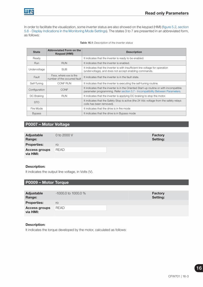
Read only Parameters
16
CFW701 | 16-3
In order to facilitate the visualization, some inverter status are also showed on the keypad (HMI) (figure 5.2, section 5.6 - Display Indications in the Monitoring Mode Settings). The states 3 to 7 are presented in an abbreviated form, as follows:
Table 16.1: Description of the inverter status
StateAbbreviated Form on the
Keypad (HMI)Description
Ready It indicates that the inverter is ready to be enabled.
Run RUN It indicates that the inverter is enabled.
Undervoltage SUBIt indicates that the inverter is with insufficient line voltage for operation (undervoltage), and does not accept enabling commands.
FaultFxxx, where xxx is the
number of the occurred faultIt indicates that the inverter is in the fault state.
Self-Tuning CONF RUN It indicates that the inverter is executing the self-tuning routine.
Configuration CONFIt indicates that the inverter is in the Oriented Start-up routine or with incompatible parameter programming. Refer section 5.7 - Incompatibility Between Parameters.
DC Braking RUN It indicates that the inverter is applying DC braking to stop the motor.
STOIt indicates that the Safety Stop is active (the 24 Vdc voltage from the safety relays coils has been removed).
Fire Mode It indicates that the drive is in fire mode
Bypass It indicates that the drive is in Bypass mode
P0007 – Motor Voltage
Adjustable Range:
0 to 2000 V Factory Setting:
Properties: ro
Access groupsvia HMI:
READ
Description:
It indicates the output line voltage, in Volts (V).
P0009 – Motor Torque
Adjustable Range:
-1000.0 to 1000.0 % Factory Setting:
Properties: ro
Access groupsvia HMI:
READ
Description:
It indicates the torque developed by the motor, calculated as follows:
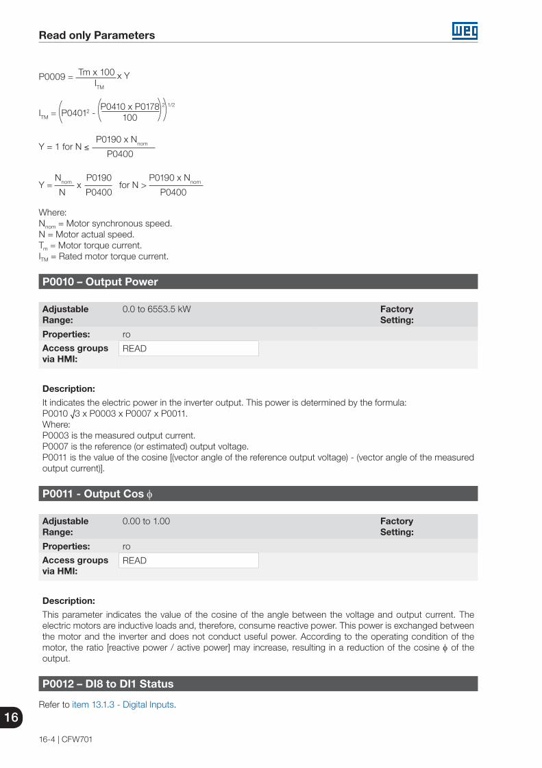
16
Read only Parameters
16-4 | CFW701
P0009 = Tm x 100 x Y ITM
ITM = P04012 - P0410 x P0178 2 1/2
100
Y = 1 for N ≤ P0190 x Nnom
P0400
Y = Nnom
x P0190
for N > P0190 x Nnom
N P0400 P0400
Where:Nnom = Motor synchronous speed.N = Motor actual speed.Tm = Motor torque current.ITM = Rated motor torque current.
P0010 – Output Power
Adjustable Range:
0.0 to 6553.5 kW Factory Setting:
Properties: ro
Access groupsvia HMI:
READ
Description:
It indicates the electric power in the inverter output. This power is determined by the formula:P0010 √3 x P0003 x P0007 x P0011.Where:P0003 is the measured output current.P0007 is the reference (or estimated) output voltage.P0011 is the value of the cosine [(vector angle of the reference output voltage) - (vector angle of the measured output current)].
P0011 - Output Cos φ
Adjustable Range:
0.00 to 1.00 Factory Setting:
Properties: ro
Access groupsvia HMI:
READ
Description:
This parameter indicates the value of the cosine of the angle between the voltage and output current. The electric motors are inductive loads and, therefore, consume reactive power. This power is exchanged between the motor and the inverter and does not conduct useful power. According to the operating condition of the motor, the ratio [reactive power / active power] may increase, resulting in a reduction of the cosine φ of the output.
P0012 – DI8 to DI1 Status
Refer to item 13.1.3 - Digital Inputs.

Read only Parameters
16
CFW701 | 16-5
P0013 – DO5 to DO1 Status
Refer to item 13.1.4 - Digital Outputs / Relays.
P0014 – AO1 Value
P0015 – AO2 Value
P0018 – AI1 Value
P0019 – AI2 Value
P0020 - AI3 Value
P0023 – Software Version
Refer to the section 6.1 - Inverter Data, for more details.
P0028 – Accessories Configuration
P0029 – Power Hardware Configuration
Refer to the section 6.1 - Inverter Data.
P0030 – IGBTs Temperature
P0034 – Internal Air Temperature
Refer to the section 15.3 - Protections.
P0036 – Heatsink Fan Speed
Adjustable Range:
0 to 15000 rpm Factory Setting:
Properties: ro
Access groupsvia HMI:
READ
Description:
It indicates the fan actual speed, in revolutions per minute (rpm).
P0037 – Motor Overload Status
Adjustable Range:
0 to 100 % Factory Setting:
Properties: ro
Access groupsvia HMI:
READ
Description:
It indicates the actual overload percentage of the motor. When this parameter reaches 100 % the fault “Motor Overload” (F072) will occur.

16
Read only Parameters
16-6 | CFW701
P0042 – Powered Time
Adjustable Range:
0 to 65535 h Factory Setting:
Properties: ro
Access groupsvia HMI:
READ
Description:
It indicates the total number of hours that the inverter remained powered.
This value is kept even when power is removed from the inverter.
P0043 – Enabled Time
Adjustable Range:
0.0 to 6553.5 h Factory Setting:
Properties: ro
Access groupsvia HMI:
READ
Description:
It indicates the total number of hours that the inverter remained enabled.
It indicates up to 6553.5 hours, and then it gets back to zero.
By setting P0204=3, the value of the parameter P0043 is reset to zero.
This value is kept even when power is removed from the inverter.
P0044 – kWh Output Energy
Adjustable Range:
0 to 65535 kWh Factory Setting:
Properties: ro
Access groupsvia HMI:
READ
Description:
It indicates the energy consumed by the motor.
It indicates up to 65535 kWh, and then it gets back to zero.
By setting P0204=4, the value of the parameter P0044 is reset to zero.
This value is kept even when power is removed from the inverter.
NOTE!The value indicated in this parameter is calculated indirectly, and must not be used to measure the energy consumption.

Read only Parameters
16
CFW701 | 16-7
P0045 – Enabled Fan Time
Adjustable Range:
0 to 65535 h Factory Setting:
Properties: ro
Access groupsvia HMI:
READ
Description:
It indicates the total number of hours that the heatsink fan remained enabled.
It indicates up to 65535 hours, and then it gets back to zero.
By setting P0204=2, the value of the parameter P0045 is reset to zero.
This value is kept even when power is removed from the inverter.
P0048 – Present Alarm
P0049 – Present Fault
Adjustable Range:
0 to 999 Factory Setting:
Properties: ro
Access groupsvia HMI:
READ
Description:
They indicate the alarm (P0048) or fault (P0049) number that occasionally is present at the inverter.
In order to understand the meaning of the codes used for faults and alarms, refer to the chapter 15 - Faults and Alarms, in this manual and the chapter 6 - Troubleshooting and Maintenance, of the user's manual.
16.1 FAULT HISTORY
In this group are described the parameters that record the last faults occurred in the inverter, together with other relevant information for the fault interpretation, as current, motor speed, etc.
NOTE!If the fault occurs simultaneously with the CFW701 power up or reset, the parameters regarding this fault, as current, motor speed, etc., may contain invalid information.
P0050 – Last Fault
P0054 – Second Fault
P0058 – Third Fault
P0062 – Fourth Fault

16
Read only Parameters
16-8 | CFW701
P0066 – Fifth Fault
Adjustable Range:
0 to 999 Factory Setting:
Properties: ro
Access groupsvia HMI:
READ
Description:
They indicate the codes from the last to the fifth fault that have occurred.
The recording system is the following:
Fxxx → P0050 → P0054 → P0058 → P0062 → P0066
P0090 – Last Fault Current
Adjustable Range:
0.0 to 4500.0 A Factory Setting:
Properties: ro
Access groupsvia HMI:
READ
Description:
It is the record of the current supplied by the inverter at the moment of the last fault occurrence.
P0091 – Last Fault DC Link Voltage
Adjustable Range:
0 to 2000 V Factory Setting:
Properties: ro
Access groupsvia HMI:
READ
Description:
It is the record of the inverter DC link voltage at the moment of the last fault occurrence.
P0092 – Last Fault Speed
Adjustable Range:
0 to 18000 rpm Factory Setting:
Properties: ro
Access groupsvia HMI:
READ
Description:
It is the record of the motor speed at the moment of the last fault occurrence.

Read only Parameters
16
CFW701 | 16-9
P0093 – Last Fault Reference
Adjustable Range:
0 to 18000 rpm Factory Setting:
Properties: ro
Access groupsvia HMI:
READ
Description:
It is the record of the speed reference at the moment of the last fault occurrence.
P0094 – Last Fault Frequency
Adjustable Range:
0.0 to 1020.0 Hz Factory Setting:
Properties: ro
Access groupsvia HMI:
READ
Description:
It is the record of the inverter output frequency at the moment of the last fault occurrence.
P0095 – Last Fault Motor Voltage
Adjustable Range:
0 to 2000 V Factory Setting:
Properties: ro
Access groupsvia HMI:
READ
Description:
It is the record of the motor voltage at the moment of the last fault occurrence.
P0096 – Last Fault DIx Status
Adjustable Range:
Bit 0 = DI1Bit 1 = DI2Bit 2 = DI3Bit 3 = DI4Bit 4 = DI5Bit 5 = DI6Bit 6 = DI7Bit 7 = DI8
Factory Setting:
Properties: ro
Access groupsvia HMI:
READ

16
Read only Parameters
16-10 | CFW701
Description:
It indicates the state of the digital inputs at the moment of the last fault occurrence.
The indication is done by means of an hexadecimal code, which when converted to binary will indicate the states “active” and “inactive” of the inputs through numbers 1 and 0.
Example: If the code presented for the parameter P0096 on the keypad (HMI) is 00A5, it will correspond to the sequence 10100101, indicating that the inputs 8, 6, 3 and 1 were active at the moment of the last fault occurrence.
Table 16.2: Example of correspondence between the P0096 hexadecimal code and the DIx states
0 0 A 50 0 0 0 0 0 0 0 1 0 1 0 0 1 0 1
No relation with the DIx(always zero)
DI8Active(+24 V)
DI7Inactive
(0 V)
DI6Active(+24 V)
DI5Inactive
(0 V)
DI4Inactive
(0 V)
DI3Active(+24 V)
DI2Inactive
(0 V)
DI1Active(+24 V)
P0097 – Last Fault DOx Status
Adjustable Range:
Bit 0 = DO1 Bit 1 = DO2 Bit 2 = DO3 Bit 3 = DO4 Bit 4 = DO5
Factory Setting:
Properties: ro
Access groupsvia HMI:
READ
Description:
It indicates the state of the digital outputs at the moment of the last fault occurrence.
The indication is done by means of an hexadecimal code, which when converted to binary will indicate the states “active” and “inactive” of the outputs through numbers 1 and 0.
Example: If the code presented for the parameter P0097 on the keypad (HMI) is 001C, it will correspond to the sequence 00011100, indicating that the outputs 5, 4, and 3 were active at the moment of the last fault occurrence.
Table 16.3: Example of correspondence between the P0097 hexadecimal code and the DOx states
0 0 1 C0 0 0 0 0 0 0 0 0 0 0 1 1 1 0 0
No relation with the DOx(always zero)
No relation with the DOx(always zero)
DO5Active(+24 V)
DO4Active(+24 V)
DO3Active(+24 V)
DO2Inactive
(0 V)
DO1Inactive
(0 V)

Communication
17
CFW701 | 17-1
17 COMMUNICATION
For the exchange of information through communication networks, the CFW701 has several standardized communication protocols, like MODBUS, BACnet and Metasys N2.
For more details regarding the inverter configuration for operating with those protocols, refer to the CFW701 communication manual. The parameters related to the communication are explained next.
17.1 RS-485 SERIAL INTERFACE
P0308 – Serial Address
P0310 – Serial Baud Rate
P0311 – Serial Interface Byte Configuration
P0312 - Serial Protocol
P0314 – Serial Watchdog
P0316 – Serial Interface Status
Those are parameters for the configuration and operation of the RS-485 serial interfaces. For a detailed description, refer to the Modbus RTU, BACnet and N2 user’s manual, supplied in electronic format on the CD-ROM that comes with the product.
17.2 COMMUNICATION BACNET
P0760 – BACnet Equipment Instance – High Part
P0761 – BACnet Equipment Instance – Low Part
P0762 – Maximum Master Number
P0763 – Maximum Number of MS/TP Frames
P0764 – I-AM Transmission
P0765 – Number of Received Tokens
Those are parameters for the configuration and operation of the communication BACnet. For a detailed description, refer to the BACnet user’s manual, supplied in electronic format on the CD-ROM that comes with the product.

17
Communication
17-2 | CFW701
17.3 COMMUNICATION METASYS N2
For a detailed description, refer to the N2 user’s manual, supplied in electronic format on the CD-ROM that comes with the product.
17.4 COMMUNICATION STATES AND COMMANDS
P0313 – Communication Error Action
P0680 – Logical Status
P0681 – Motor Speed in 13 Bits
P0695 – Settings for the Digital Outputs
P0696 – Value 1 for Analog Outputs
P0697 – Value 2 for Analog Outputs
P0682 – Serial Control Word
P0683 – Serial Speed Reference
Those parameters are used for monitoring and controlling the CFW701 inverter by means of communication interfaces. For a detailed description, refer to the communication manual of the user interface. These manuals are supplied in electronic format on the CD-ROM that comes with the product.

SoftPLC
18
CFW701 | 18-1
18 SOFTPLC [50]
The SoftPLC function allows the frequency inverter to assume PLC (Programmable Logical Controller) functions. For more details regarding the programming of those functions in the CFW701, refer to the CFW701 SoftPLC manual. The parameters related to the SoftPLC are described next.
P1000 – SoftPLC Status
Adjustable Range:
0 = No Application1 = Installing App.2 = Incompatible App.3 = App. Stopped 4 = App. Running
Factory Setting:
Properties: ro
Access groupsvia HMI:
HVAC or READ
Description:
It allows the user to visualize the current SoftPLC status. If there is no installed application, the parameters from P1010 to P1099 will not be showed on the keypad.
If this parameter presents the option 2 (“Incompat. App.”), it indicates that the version that has been loaded in the flash memory board is not compatible with the current CFW701 firmware.
In this case it is necessary to recompile the project in the WLP software with the new CFW701 version and download it again. If this is not possible, the upload of this application with the WLP can be done since the password of the application software is known or it is not enabled.
P1001 – SoftPLC Command
Adjustable Range:
0 = Stop Application1 = Run Application2 = Delete Application
Factory Setting:
0
Properties:
Access groupsvia HMI:
HVAC
Description:
It allows stopping, running or excluding the installed application, however, the motor must be disabled.
P1002 – Scan Cycle Time
Adjustable Range:
0.0 to 999.9 ms Factory Setting:
Properties: ro
Access groupsvia HMI:
HVAC or READ
Description:
It consists in the application scanning time. The bigger the application, the longer the scanning time will be.

18
SoftPLC
18-2 | CFW701
P1003 – SoftPLC Application Selection
Adjustable Range:
0 = User1 = HVAC
Factory Setting:
1
Properties: cfg
Access groupsvia HMI:
HVAC
Description:
It allows the user to select the CFW701 built in applications.
Table 18.1: Parameter P1003 option description
P1003 Description 0 The application that will run in the SoftPLC is that loaded by the user via ladder programming.1 HVAC. Further detail on chapter 19 - HVAC Functions.
NOTE!Refer to SoftPLC manual for more information about the CFW701 user applications.
From P1010 to P1099 – SoftPLC Parameters
Adjustable Range:
-32768 to 32767 Factory Setting:
0
Properties: cfg
Access groupsvia HMI:
HVAC
Description:
They consist of parameters defined by the selected application in parameter P1003.

HVAC Functions
19
CFW701 | 19-1
19 HVAC FUNCTIONS
The CFW701 frequency inverter is an equipment optimized for applications in heating, ventilation, air conditioning and refrigeration, i.e., HVAC market. It was implemented some functionalities / protections commons for this market, how:
Fire Mode Bypass mode Automatic energy saving Short cycle protection Dry pump Broken belt Filter maintenance alarm Main PID controller for motor control Sleep mode for Main PID controller External PID controller 1 External PID controller 2
19.1 FIRE MODE
DANGER! Notice that the CFW701 is just one of the components of the HVAC system, and it is configurable
for different functions, including the “Fire Mode” function. Thus, the full operation of the “Fire Mode” function depends on the accuracy of the project and
on the joint performance of the components of the system. Ventilation systems that work on life safety applications must be approved by the Fire Department
and/or another competent public authority. The non-interruption of the operation of the CFW701, when configured for operation in the “Fire
Mode” function, is critical and must be taken into account in the preparation of safety plans in the environments in which they are installed, since damages may occur to the CFW701 itself and to other components of the HVAC system, to the environment in which it is installed and to people with risk of death.
The operation in the “Fire Mode” function may, under certain circumstances, result in fire, since the protection devices will be disabled.
Only personnel from engineering and safety must consider the configuration of the equipment for the “Fire Mode” function.
WEG strongly recommends to follow the cares and procedures above before using the CFW701 in the “Fire Mode” function, and it will not be liable to the final user or third parties for any losses or damages direct or indirectly incurred due to the programming and operation of the CFW701 in “Fire Mode” regime, considering the critical and special use of this function.
NOTE!When the user activates the "Fire Mode" function, he/she acknowledges that the protection functions of the CFW701 are disabled, which may result in damages to the CFW701 itself, to the components connected to it, to the environment in which it is installed and to people present in such environment; therefore, the user takes full responsibility for the risks arising from such operating condition. Operation with the “Fire Mode” function programmed voids the warranty of the product. The operation in this condition is internally registered by the CFW701 and must be validated by a duly qualified professional of engineering and occupational safety, since such procedure significantly increases the operating risk.
The “Fire Mode” function is intended to make the frequency inverter continue to drive the motor even under adverse conditions, inhibiting most faults generated by the frequency inverter in order to protect itself or protect the motor. The “Fire Mode” is selected by driving a digital input previously set to “Fire Mode" with logic level "0" (0 V) at the input terminals. When the drive enters the “Fire Mode”, the alarm "A211" will be generated on the HMI (keypad) and the status of the operation mode will be updated in parameter P0006.
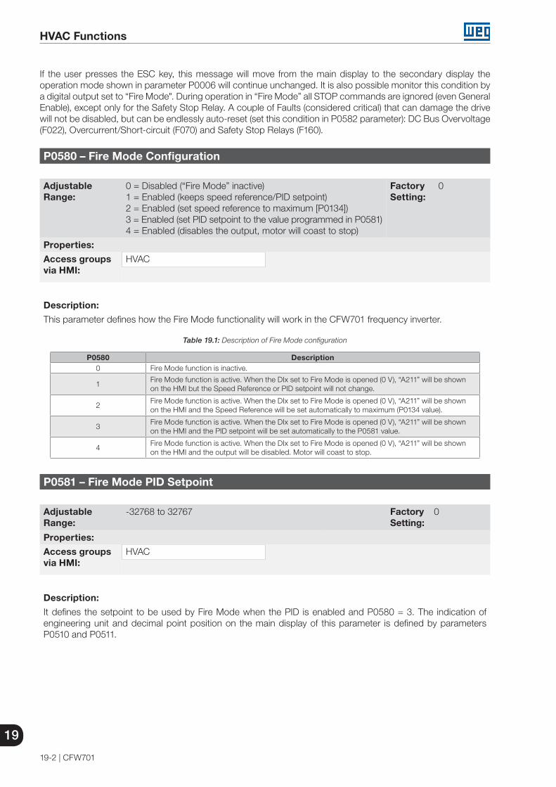
19
HVAC Functions
19-2 | CFW701
If the user presses the ESC key, this message will move from the main display to the secondary display the operation mode shown in parameter P0006 will continue unchanged. It is also possible monitor this condition by a digital output set to “Fire Mode". During operation in “Fire Mode” all STOP commands are ignored (even General Enable), except only for the Safety Stop Relay. A couple of Faults (considered critical) that can damage the drive will not be disabled, but can be endlessly auto-reset (set this condition in P0582 parameter): DC Bus Overvoltage (F022), Overcurrent/Short-circuit (F070) and Safety Stop Relays (F160).
P0580 – Fire Mode Configuration
Adjustable Range:
0 = Disabled (“Fire Mode” inactive)1 = Enabled (keeps speed reference/PID setpoint)2 = Enabled (set speed reference to maximum [P0134])3 = Enabled (set PID setpoint to the value programmed in P0581)4 = Enabled (disables the output, motor will coast to stop)
Factory Setting:
0
Properties:
Access groupsvia HMI:
HVAC
Description:
This parameter defines how the Fire Mode functionality will work in the CFW701 frequency inverter.
Table 19.1: Description of Fire Mode configuration
P0580 Description0 Fire Mode function is inactive.
1Fire Mode function is active. When the DIx set to Fire Mode is opened (0 V), “A211” will be shown on the HMI but the Speed Reference or PID setpoint will not change.
2Fire Mode function is active. When the DIx set to Fire Mode is opened (0 V), “A211” will be shown on the HMI and the Speed Reference will be set automatically to maximum (P0134 value).
3Fire Mode function is active. When the DIx set to Fire Mode is opened (0 V), “A211” will be shown on the HMI and the PID setpoint will be set automatically to the P0581 value.
4Fire Mode function is active. When the DIx set to Fire Mode is opened (0 V), “A211” will be shown on the HMI and the output will be disabled. Motor will coast to stop.
P0581 – Fire Mode PID Setpoint
Adjustable Range:
-32768 to 32767 Factory Setting:
0
Properties:
Access groupsvia HMI:
HVAC
Description:
It defines the setpoint to be used by Fire Mode when the PID is enabled and P0580 = 3. The indication of engineering unit and decimal point position on the main display of this parameter is defined by parameters P0510 and P0511.

HVAC Functions
19
CFW701 | 19-3
P0582 – Fire Mode Auto-reset Configuration
Adjustable Range:
0 = Limited1 = Unlimited
Factory Setting:
0
Properties:
Access groupsvia HMI:
HVAC
Description:
This parameter defines how the auto-reset functionality will work in Fire Mode when a critical fault occur (DC Bus Overvoltage [F022], Overcurrent/Short-circuit [F070] and Safety Stop Relays [F160]).
Table 19.2: Description of Auto-reset configuration in Fire Mode
P0582 Description0 Limited. Auto-reset works as defined in P0340 parameter.
1Unlimited. The auto-reset happens after 1 s of a critical failure detection regardless of the value set in P0340.
19.2 BYPASS MODE
The Bypass Mode allows switching the motor controlled by the CFW701 inverter to be fed directly by the mains using an external contactor the will make the connection. In order to achieve that, two contactors will be necessary, one for connecting the motor to the drive and another for connecting the motor to the mains.
The contactors will be driven by two digital outputs (DOx) previously programmed for “Drive Bypass Contactor” and “Mains Bypass Contactor”. The drive will ensure the correct interlocking.
When entering Bypass Mode, the Alarm “A210” will be generated and shown at the HMI. This state can also be verified in the Parameter P0006 and P0680.
The drive will enter in the Bypass Mode when the digital input (DIx) previously programmed for “Bypass” is set to logic level high (24 V). At this moment the drive will perform a “General Disable” command (the motor will coast to stop) and will signal that the Bypass Mode is active in both P0006 and P0680. Following that, the digital output DOx set to “Drive Bypass Contactor” is reset after a delay for demagnetizing the motor. This delay is fixed in 3 s if the motor speed is greater or equal to the motor rated speed or set to 3s*(Speed/Rated Speed) otherwise. The next step is to set the output configured as “Mains Bypass Contactor” to connect the motor to the mains, action taken after a delay set in P0584 to ensure that the drive output contactor is effectively open. The drive is then bypassed and will stay so as long as the digital input set as “Bypass” is set (24 V).
As soon as the digital input set to “Bypass” is reset (0 V), the output programmed for “Mains Bypass Contactor” is also reset, disconnecting the motor from the mains. The drive is kept in Bypass Mode until a “run” command is received by the drive, when the “Bypass” digital input is checked whether it’s still deactivated and, if so, the state of P0006 and P0680 is updated to reflect the exit from the Bypass Mode. No longer in Bypass Mode, the drive waits for the demagnetization of the motor and sets the “Drive Bypass Contactor” output, connecting the motor back to the drive output. After another delay (set by P0584) for ensuring that the contactor is effectively closed, the inverter output is enabled again to drive the motor.
This activation logic is shown in figure 19.1.

19
HVAC Functions
19-4 | CFW701
DIx/Fault
N
DOxLine
DOxdrive
RUN
P0584
P0006
P0680
P0584tdesmtdesm
Bypass
CFW701 M~
Figure 19.1: Bypass mode activation logic
An example of connecting the bypass can be seen in figure 19.2. Setting used in this example:
P0268 = 23 (DI6 = Bypass Mode)P0275 = 39 (RL1 = Drive Bypass Contactor)P0276 = 40 (RL2 = Mains Bypass Contactor)P0583 = 1 (Bypass enabled by DIx)P0584 = 0.30 s

HVAC Functions
19
CFW701 | 19-5
Bypass command
MDW16 Circuitbreaker
MDW40 Circuitbreaker
PDWXC1
CFW701 220 V - 64 / 5 A
RL2
-C
RL2
-NA
RL1
-NA
RL1
-C
24 V
DC
DI6
CO
M
DG
ND
220 V
R S T U V W
2 4 6 A2- 2 4 6 A2-
1 3 5 A1+ 1 3 5 A1+
CWC07 - 10E Mains contactor
CWC07 - 10E Drive contactor
220 V - 3 A 4 poles - 1 HP 60 Hz
W V U
11 15 18 35 36 31 32 33
Figure 19.2: Bypass mode example
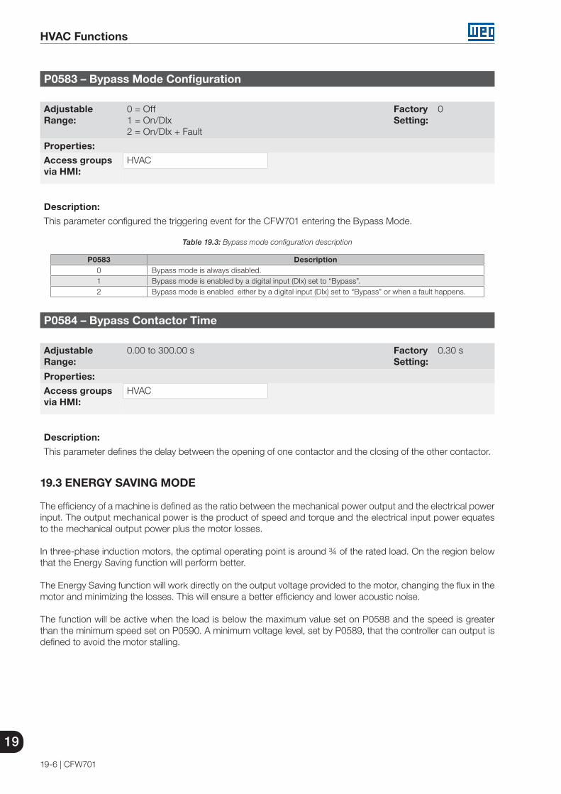
19
HVAC Functions
19-6 | CFW701
P0583 – Bypass Mode Configuration
Adjustable Range:
0 = Off 1 = On/DIx2 = On/DIx + Fault
Factory Setting:
0
Properties:
Access groupsvia HMI:
HVAC
Description:
This parameter configured the triggering event for the CFW701 entering the Bypass Mode.
Table 19.3: Bypass mode configuration description
P0583 Description0 Bypass mode is always disabled.1 Bypass mode is enabled by a digital input (DIx) set to “Bypass”.2 Bypass mode is enabled either by a digital input (DIx) set to “Bypass” or when a fault happens.
P0584 – Bypass Contactor Time
Adjustable Range:
0.00 to 300.00 s Factory Setting:
0.30 s
Properties:
Access groupsvia HMI:
HVAC
Description:
This parameter defines the delay between the opening of one contactor and the closing of the other contactor.
19.3 ENERGY SAVING MODE
The efficiency of a machine is defined as the ratio between the mechanical power output and the electrical power input. The output mechanical power is the product of speed and torque and the electrical input power equates to the mechanical output power plus the motor losses.
In three-phase induction motors, the optimal operating point is around ¾ of the rated load. On the region below that the Energy Saving function will perform better.
The Energy Saving function will work directly on the output voltage provided to the motor, changing the flux in the motor and minimizing the losses. This will ensure a better efficiency and lower acoustic noise. The function will be active when the load is below the maximum value set on P0588 and the speed is greater than the minimum speed set on P0590. A minimum voltage level, set by P0589, that the controller can output is defined to avoid the motor stalling.

HVAC Functions
19
CFW701 | 19-7
P0407 – Motor Rated Power Factor
Adjustable Range:
0.50 to 0.99 Factory Setting:
0.68
Properties: cfg, V/f and VVW
Access groupsvia HMI:
Description:
It sets the Motor Rated Power Factor.
Note: On some applications this value should be set slightly lower than the value on the motor plate. These can be identified by an increase on the motor current when enabling the energy saving function. In these cases, reduce this value slowly until the minimum output current is found.
For information on the use of P0407 in the VVW motor control mode, please check the chapter 10 - VVW Control, of this manual.
P0588 – Energy Saving Max. Torque
Adjustable Range:
0 to 85 % Factory Setting:
0 %
Properties: V/f
Access groupsvia HMI:
HVAC
Description:
This parameter define the torque value on which the energy saving function is activated. Setting this value to 0 % effectively disables the function.
The recommended value for this parameter with the function active is 60 %, but other values can be used depending on the application and the motor.
P0589 – Energy Saving Min. Mag.
Adjustable Range:
40 to 80 % Factory Setting:
40 %
Properties: V/f
Access groupsvia HMI:
HVAC
Description:
This parameter defines the minimum voltage level that will be output to the motor with the energy saving function active. The setting is a proportion to the voltage imposed by the V/f curve.

19
HVAC Functions
19-8 | CFW701
P0590 – Energy Saving Min. Speed
Adjustable Range:
360 to 18000 rpm Factory Setting:
600 rpm
Properties: V/f
Access groupsvia HMI:
HVAC
Description:
This parameter defines the minimum speed on which the energy saving function will be active. Speeds lower that this will disable the function.
The histeresis for the minimum speed level is 2 Hz.
P0591 – Energy Saving Histeresis
Adjustable Range:
0 to 30 % Factory Setting:
10 %
Properties: V/f
Access groupsvia HMI:
HVAC
Description:
This is the torque histeresis used to turning the energy saving function on and off.
Too low values will cause the output current to oscilate. Simply increasing the value should solve this.
NOTE!These parameters can’t be set while the motor is running.
19.4 SHORT CYCLE PROTECTION
The short cycles protection has the objective of avoiding turning on and off a compressor with too short time periods. A minimum on and a minimum off time are set so that during these periods stop and run commands are ignored, with the exception of “general disable” and faults.
P0585 – Short Cycle Protection Config
Adjustable Range:
0 = Off 1 = On
Factory Setting:
0
Properties:
Access groupsvia HMI:
HVAC
Description:
This parameter define whether the short cycles protection is active or not.

HVAC Functions
19
CFW701 | 19-9
P0586 – Minimum RUN Time
Adjustable Range:
0 to 650.00 s Factory Setting:
5.00 s
Properties:
Access groupsvia HMI:
HVAC
Description:
Defines the minimum time that compressor will be kept on, ignoring stop commands.
P0587 – Minimum STOP Time
Adjustable Range:
0 to 650.00 s Factory Setting:
5.00 s
Properties:
Access groupsvia HMI:
HVAC
Description:
Defines the minimum time that the compressor will be kept off, ignoring run commands.
19.5 DRY PUMP
This parameter group allows the user to configure the dry pump operation detection.
The dry pump detection is intended to avoid the pump driven by frequency inverter to operate at vacuum, i.e., without the liquid being pumped. This is done by detecting the operation speed in conjunction with the motor torque.
P1042 – Dry Pump Detection Configuration
Adjustable Range:
0 = Disable 1 = Enable and only alarm2 = Enable and generate fault
Factory Setting:
0
Properties:
Access groupsvia HMI:
HVAC
Description:
This parameter defines how the dry pump detection functionality will go act in the CFW701 frequency inverter.
Table 19.4: Description of dry pump detection configuration
P1042 Description0 It defines will not be done the dry pump detection.
1It defines the dry pump detection will be enabled and only will generate the alarm message “A0766: Dry pump detected”, i.e., the CFW701 frequency inverter will continue control the motor.
2It defines the dry pump detection will be enabled and will generate the alarm message “A0766: Dry pump detected” during motor deceleration and the fault “F0767: Dry pump detected” in the CFW701 frequency inverter after stopping the motor.
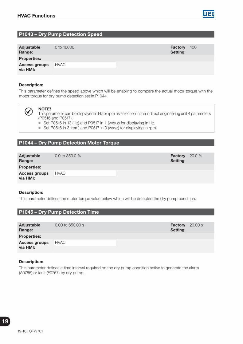
19
HVAC Functions
19-10 | CFW701
P1043 – Dry Pump Detection Speed
Adjustable Range:
0 to 18000 Factory Setting:
400
Properties:
Access groupsvia HMI:
HVAC
Description:
This parameter defines the speed above which will be enabling to compare the actual motor torque with the motor torque for dry pump detection set in P1044.
NOTE!This parameter can be displayed in Hz or rpm as selection in the indirect engineering unit 4 parameters (P0516 and P0517):
Set P0516 in 13 (Hz) and P0517 in 1 (wxy.z) for displaying in Hz. Set P0516 in 3 (rpm) and P0517 in 0 (wxyz) for displaying in rpm.
P1044 – Dry Pump Detection Motor Torque
Adjustable Range:
0.0 to 350.0 % Factory Setting:
20.0 %
Properties:
Access groupsvia HMI:
HVAC
Description:
This parameter defines the motor torque value below which will be detected the dry pump condition.
P1045 – Dry Pump Detection Time
Adjustable Range:
0.00 to 650.00 s Factory Setting:
20.00 s
Properties:
Access groupsvia HMI:
HVAC
Description:
This parameter defines a time interval required on the dry pump condition active to generate the alarm (A0766) or fault (F0767) by dry pump.

HVAC Functions
19
CFW701 | 19-11
19.6 BROKEN BELT
This parameter group allows the user to configure the broken belt operation detection.
The broken belt detection is intended to avoid the motor driven by frequency inverter to operate empty, i.e., to a mechanical problem between the motor and load, it continues to operate. This is done by detecting the operation speed in conjunction with the motor torque.
P1046 – Broken Belt Detection Configuration
Adjustable Range:
0 = Disable 1 = Enable and only alarm2 = Enable and generate fault
Factory Setting:
0
Properties:
Access groupsvia HMI:
HVAC
Description:
This parameter defines how the broken belt detection functionality will go act in the CFW701 frequency inverter.
Table 19.5: Description of broken belt detection configuration
P1046 Description0 It defines will not be done the broken belt detection.
1It defines the broken belt detection will be enabled and only will generate the alarm message “A0768: Broken belt detected”, i.e., the CFW701 frequency inverter will continue control the motor.
2It defines the broken belt detection will be enabled and will generate the alarm message “A0768: Broken belt detected” during motor deceleration and the fault “F0769: Broken belt detected” in the CFW701 frequency inverter after stopping the motor.
P1047 – Broken Belt Detection Speed
Adjustable Range:
0 to 18000 Factory Setting:
400
Properties:
Access groupsvia HMI:
HVAC
Description:
This parameter defines the speed above which will be enabling to compare the actual motor torque with the motor torque for broken belt detection set in P1048.
NOTE!This parameter can be displayed in Hz or rpm as selection in the indirect engineering unit 4 parameters (P0516 and P0517):
Set P0516 in 13 (Hz) and P0517 in 1 (wxy.z) for displaying in Hz. Set P0516 in 3 (rpm) and P0517 in 0 (wxyz) for displaying in rpm.

19
HVAC Functions
19-12 | CFW701
P1048 – Broken Belt Detection Motor Torque
Adjustable Range:
0.0 to 350.0 % Factory Setting:
20.0 %
Properties:
Access groupsvia HMI:
HVAC
Description:
This parameter defines the motor torque value below which will be detected the broken belt condition.
P1049 – Broken Belt Detection Time
Adjustable Range:
0.00 to 650.00 s Factory Setting:
20.00 s
Properties:
Access groupsvia HMI:
HVAC
Description:
This parameter defines a time interval required on the broken belt condition active to generate the alarm (A0768) or fault (F0769) by broken belt.
19.7 FILTER MAINTENANCE ALARM
This parameter group allows the user to configure the filter maintenance alarm operation.
The filter maintenance alarm is intended to alert the user of the need to change the filter system. It has the preventive maintenance function in the filtration system.
P1050 – Filter Maintenance Alarm Configuration
Adjustable Range:
0 = Disable 1 = Enable and only alarm2 = Enable and generate fault
Factory Setting:
0
Properties:
Access groupsvia HMI:
HVAC
Description:
This parameter defines how the filter maintenance alarm functionality will go act in the CFW701 frequency inverter.
Table 19.6: Description of filter maintenance alarm configuration
P1050 Description
0 It defines will not be done the counting of operation time for change the filter system. Also resets the operation time for filter maintenance alarm in P1056 parameter.
1It defines the counting of operation time for filter maintenance alarm will be enabled and only will generate the alarm message “A0770: Filter maintenance”, i.e., the CFW701 frequency inverter will continue control the motor.
2It defines the counting of operation time for filter maintenance alarm will be enabled and will generate the alarm message “A0770: Filter maintenance” during the motor deceleration and the fault “F0771: Filter maintenance” in the CFW701 frequency inverter after stopping the motor.
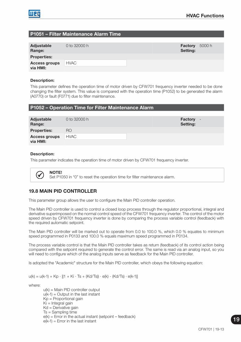
HVAC Functions
19
CFW701 | 19-13
P1051 – Filter Maintenance Alarm Time
Adjustable Range:
0 to 32000 h Factory Setting:
5000 h
Properties:
Access groupsvia HMI:
HVAC
Description:
This parameter defines the operation time of motor driven by CFW701 frequency inverter needed to be done changing the filter system. This value is compared with the operation time (P1052) to be generated the alarm (A0770) or fault (F0771) due to filter maintenance.
P1052 – Operation Time for Filter Maintenance Alarm
Adjustable Range:
0 to 32000 h Factory Setting:
-
Properties: RO
Access groupsvia HMI:
HVAC
Description:
This parameter indicates the operation time of motor driven by CFW701 frequency inverter.
NOTE!Set P1050 in “0” to reset the operation time for filter maintenance alarm.
19.8 MAIN PID CONTROLLER
This parameter group allows the user to configure the Main PID controller operation.
The Main PID controller is used to control a closed loop process through the regulator proportional, integral and derivative superimposed on the normal control speed of the CFW701 frequency inverter. The control of the motor speed driven by CFW701 frequency inverter is done by comparing the process variable control (feedback) with the required automatic setpoint.
The Main PID controller will be marked out to operate from 0.0 to 100.0 %, which 0.0 % equates to minimum speed programmed in P0133 and 100.0 % equals maximum speed programmed in P0134.
The process variable control is that the Main PID controller takes as return (feedback) of its control action being compared with the setpoint required to generate the control error. The same is read via an analog input, so you will need to configure which of the analog inputs serve as feedback for the Main PID controller.
Is adopted the "Academic" structure for the Main PID controller, which obeys the following equation:
u(k) = u(k-1) + Kp ∙ [(1 + Ki ∙ Ts + (Kd/Ts)) ∙ e(k) - (Kd/Ts) ∙ e(k-1)]
where: u(k) = Main PID controller output u(k-1) = Output in the last instant Kp = Proportional gain Ki = Integral gain Kd = Derivative gain Ts = Sampling time e(k) = Error in the actual instant (setpoint – feedback) e(k-1) = Error in the last instant

19
HVAC Functions
19-14 | CFW701
P1011 – Main PID Controller Automatic Setpoint
Adjustable Range:
-32768 to 32767 Factory Setting:
0
Properties:
Access groupsvia HMI:
HVAC
Description:
This parameter defines the value of Main PID controller setpoint in engineering unit when it is in automatic mode.
NOTE!This parameter is displayed as the selection in the indirect engineering unit 1 parameters (P0510 and P0511).
P1014 – Main PID Controller Manual Setpoint
Adjustable Range:
0.0 to 100.0 % Factory Setting:
0.0 %
Properties:
Access groupsvia HMI:
HVAC
Description:
This parameter defines the value of Main PID controller setpoint when it is in manual mode.
P1015 – Main PID Controller Feedback
Adjustable Range:
-32768 to 32767 Factory Setting:
-
Properties: RO
Access groupsvia HMI:
HVAC
Description:
This parameter indicates the actual value of Main PID controller feedback (process variable) in engineering unit.
NOTE!This parameter is displayed as the selection in the indirect engineering unit 1 parameters (P0510 and P0511).
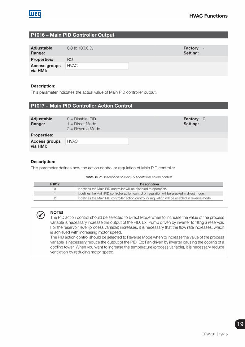
HVAC Functions
19
CFW701 | 19-15
P1016 – Main PID Controller Output
Adjustable Range:
0.0 to 100.0 % Factory Setting:
-
Properties: RO
Access groupsvia HMI:
HVAC
Description:
This parameter indicates the actual value of Main PID controller output.
P1017 – Main PID Controller Action Control
Adjustable Range:
0 = Disable PID 1 = Direct Mode2 = Reverse Mode
Factory Setting:
0
Properties:
Access groupsvia HMI:
HVAC
Description:
This parameter defines how the action control or regulation of Main PID controller.
Table 19.7: Description of Main PID controller action control
P1017 Description0 It defines the Main PID controller will be disabled to operation.1 It defines the Main PID controller action control or regulation will be enabled in direct mode.2 It defines the Main PID controller action control or regulation will be enabled in reverse mode.
NOTE!The PID action control should be selected to Direct Mode when to increase the value of the process variable is necessary increase the output of the PID. Ex: Pump driven by inverter to filling a reservoir. For the reservoir level (process variable) increases, it is necessary that the flow rate increases, which is achieved with increasing motor speed. The PID action control should be selected to Reverse Mode when to increase the value of the process variable is necessary reduce the output of the PID. Ex: Fan driven by inverter causing the cooling of a cooling tower. When you want to increase the temperature (process variable), it is necessary reduce ventilation by reducing motor speed.
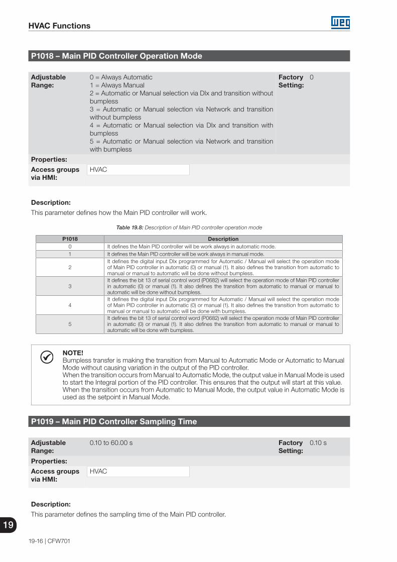
19
HVAC Functions
19-16 | CFW701
P1018 – Main PID Controller Operation Mode
Adjustable Range:
0 = Always Automatic 1 = Always Manual2 = Automatic or Manual selection via DIx and transition without bumpless3 = Automatic or Manual selection via Network and transition without bumpless4 = Automatic or Manual selection via DIx and transition with bumpless5 = Automatic or Manual selection via Network and transition with bumpless
Factory Setting:
0
Properties:
Access groupsvia HMI:
HVAC
Description:
This parameter defines how the Main PID controller will work.
Table 19.8: Description of Main PID controller operation mode
P1018 Description0 It defines the Main PID controller will be work always in automatic mode.1 It defines the Main PID controller will be work always in manual mode.
2It defines the digital input DIx programmed for Automatic / Manual will select the operation mode of Main PID controller in automatic (0) or manual (1). It also defines the transition from automatic to manual or manual to automatic will be done without bumpless.
3It defines the bit 13 of serial control word (P0682) will select the operation mode of Main PID controller in automatic (0) or manual (1). It also defines the transition from automatic to manual or manual to automatic will be done without bumpless.
4It defines the digital input DIx programmed for Automatic / Manual will select the operation mode of Main PID controller in automatic (0) or manual (1). It also defines the transition from automatic to manual or manual to automatic will be done with bumpless.
5It defines the bit 13 of serial control word (P0682) will select the operation mode of Main PID controller in automatic (0) or manual (1). It also defines the transition from automatic to manual or manual to automatic will be done with bumpless.
NOTE!Bumpless transfer is making the transition from Manual to Automatic Mode or Automatic to Manual Mode without causing variation in the output of the PID controller.When the transition occurs from Manual to Automatic Mode, the output value in Manual Mode is used to start the Integral portion of the PID controller. This ensures that the output will start at this value.When the transition occurs from Automatic to Manual Mode, the output value in Automatic Mode is used as the setpoint in Manual Mode.
P1019 – Main PID Controller Sampling Time
Adjustable Range:
0.10 to 60.00 s Factory Setting:
0.10 s
Properties:
Access groupsvia HMI:
HVAC
Description:
This parameter defines the sampling time of the Main PID controller.
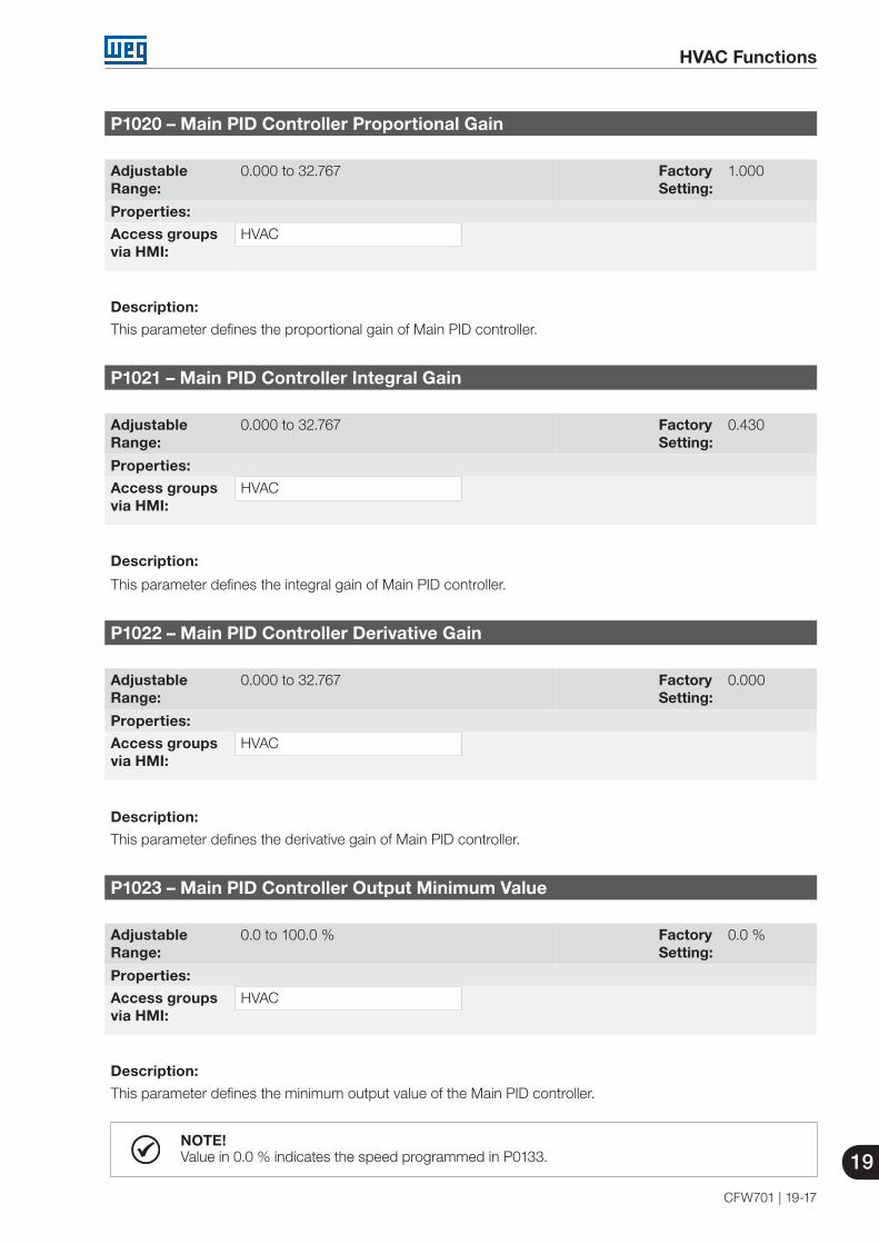
HVAC Functions
19
CFW701 | 19-17
P1020 – Main PID Controller Proportional Gain
Adjustable Range:
0.000 to 32.767 Factory Setting:
1.000
Properties:
Access groupsvia HMI:
HVAC
Description:
This parameter defines the proportional gain of Main PID controller.
P1021 – Main PID Controller Integral Gain
Adjustable Range:
0.000 to 32.767 Factory Setting:
0.430
Properties:
Access groupsvia HMI:
HVAC
Description:
This parameter defines the integral gain of Main PID controller.
P1022 – Main PID Controller Derivative Gain
Adjustable Range:
0.000 to 32.767 Factory Setting:
0.000
Properties:
Access groupsvia HMI:
HVAC
Description:
This parameter defines the derivative gain of Main PID controller.
P1023 – Main PID Controller Output Minimum Value
Adjustable Range:
0.0 to 100.0 % Factory Setting:
0.0 %
Properties:
Access groupsvia HMI:
HVAC
Description:
This parameter defines the minimum output value of the Main PID controller.
NOTE!Value in 0.0 % indicates the speed programmed in P0133.
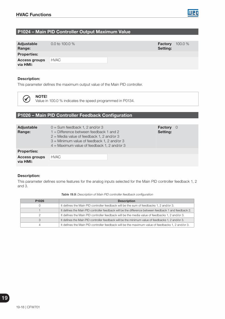
19
HVAC Functions
19-18 | CFW701
P1024 – Main PID Controller Output Maximum Value
Adjustable Range:
0.0 to 100.0 % Factory Setting:
100.0 %
Properties:
Access groupsvia HMI:
HVAC
Description:
This parameter defines the maximum output value of the Main PID controller.
NOTE!Value in 100.0 % indicates the speed programmed in P0134.
P1026 – Main PID Controller Feedback Configuration
Adjustable Range:
0 = Sum feedback 1, 2 and/or 31 = Difference between feedback 1 and 22 = Media value of feedback 1, 2 and/or 33 = Minimum value of feedback 1, 2 and/or 34 = Maximum value of feedback 1, 2 and/or 3
Factory Setting:
0
Properties:
Access groupsvia HMI:
HVAC
Description:
This parameter defines some features for the analog inputs selected for the Main PID controller feedback 1, 2 and 3.
Table 19.9: Description of Main PID controller feedback configuration
P1026 Description0 It defines the Main PID controller feedback will be the sum of feedbacks 1, 2 and/or 3.
1 It defines the Main PID controller feedback will be the difference between feedback 1 and feedback 2.
2 It defines the Main PID controller feedback will be the media value of feedbacks 1, 2 and/or 3.
3 It defines the Main PID controller feedback will be the minimum value of feedbacks 1, 2 and/or 3.
4 It defines the Main PID controller feedback will be the maximum value of feedbacks 1, 2 and/or 3.

HVAC Functions
19
CFW701 | 19-19
P1027 – Main PID Controller Feedback Minimum Level
Adjustable Range:
-32768 to 32767 Factory Setting:
0
Properties:
Access groupsvia HMI:
HVAC
Description:
This parameter defines the minimum value of the analog input sensor of the Main PID controller feedback for conversion into engineering unit.
NOTE!This parameter is displayed as the selection in the indirect engineering unit 1 parameters (P0510 and P0511).
P1028 – Main PID Controller Feedback Maximum Level
Adjustable Range:
-32768 to 32767 Factory Setting:
1000
Properties:
Access groupsvia HMI:
HVAC
Description:
This parameter defines the maximum value of the analog input sensor of the Main PID controller feedback for conversion into engineering unit.
NOTE!This parameter is displayed as the selection in the indirect engineering unit 1 parameters (P0510 and P0511).

19
HVAC Functions
19-20 | CFW701
P1030 – Main PID Controller Feedback Alarms Configuration
Adjustable Range:
0 = Disable1 = Enable and only alarm2 = Enable and generate fault (stops the motor before)
Factory Setting:
0
Properties:
Access groupsvia HMI:
HVAC
Description:
This parameter defines how the Main PID controller feedback alarms for low or high level will go act in the CFW701 frequency inverter.
Table 19.10: Description of Main PID controller feedback alarms configuration
P1030 Description0 It defines the Main PID controller feedback alarms for low or high level will be disabled.
1It defines the Main PID controller feedback alarms for low or high level will be enabled and only will generate the respective alarm message (A0760 or A0762), leaving the Main PID controller active and controlling the motor driven by CFW701 frequency inverter.
2 It defines the Main PID controller feedback alarms for low or high level will be enabled and will generate the fault (A0760 or F0761) in the CFW701 frequency inverter after stopping the motor.
P1031 – Main PID Controller Feedback Alarm Low Level Value
Adjustable Range:
-32768 to 32767 Factory Setting:
50
Properties:
Access groupsvia HMI:
HVAC
Description:
This parameter defines the feedback value below which is considered low level for the sensor of analog input of the Main PID controller feedback in engineering unit.
NOTE!This parameter is displayed as the selection in the indirect engineering unit 1 parameters (P0510 and P0511).

HVAC Functions
19
CFW701 | 19-21
P1032 – Main PID Controller Feedback Alarm Low Level Time
Adjustable Range:
0.00 to 650.00 s Factory Setting:
5.00 s
Properties:
Access groupsvia HMI:
HVAC
Description:
This parameter defines the time on the Main PID controller feedback low level condition active to be generated the alarm message “A0760: Low level for Main PID controller feedback”. With P1030 in 2, will be generated a fault “F0761: Low level for Main PID controller feedback” in the CFW701 frequency inverter after stopping the motor.
NOTE!Value in 0.00 s disables the alarm detection.
P1033 – Main PID Controller Feedback Alarm High Level Value
Adjustable Range:
-32768 to 32767 Factory Setting:
900
Properties:
Access groupsvia HMI:
HVAC
Description:
This parameter defines the feedback value above which is considered high level for the sensor of analog input of the Main PID controller feedback in engineering unit.
NOTE!This parameter is displayed as the selection in the indirect engineering unit 1 parameters (P0510 and P0511).
P1034 – Main PID Controller Feedback Alarm High Level Time
Adjustable Range:
0.00 to 650.00 s Factory Setting:
5.00 s
Properties:
Access groupsvia HMI:
HVAC
Description:
This parameter defines the time on the Main PID controller feedback high level condition active to be generated the alarm message “A0762: High level for Main PID controller feedback”. With P1030 in 2, will be generated a fault “F0763: High level for Main PID controller feedback” in the CFW701 frequency inverter after stopping the motor.
NOTE!Value in 0.00 s disables the alarm detection.

19
HVAC Functions
19-22 | CFW701
19.8.1 Sleep Mode
This parameter group allows the user to configure the sleep mode operation for Main PID controller.
Sleep Mode is a state of the controlled system where the control request is null or almost null, and may at this moment, stop the motor driven by CFW701 frequency inverter; that avoids the motor remain in operation at a low speed that contributes little or nothing in controlled system. However, the control variable (feedback) continues to be monitored so that when necessary (a level below a setpoint required), the controlled system can start the motor again (wake up mode).
NOTE!The sleep mode works only if Main PID controller is enabled and in automatic mode.
P1036 – Main PID Controller Sleep Mode Speed
Adjustable Range:
0 to 18000 Factory Setting:
350
Properties:
Access groupsvia HMI:
HVAC
Description:
This parameter defines the motor speed below which will be considered that the speed control is low, thus activating the sleep mode.
NOTE!This parameter can be displayed in Hz or rpm as selection in the indirect engineering unit 4 parameters (P0516 and P0517):
Set P0516 in 13 (Hz) and P0517 in 1 (wxy.z) for displaying in Hz. Set P0516 in 3 (rpm) and P0517 in 0 (wxyz) for displaying in rpm.
P1037 – Main PID Controller Sleep Mode Time
Adjustable Range:
0.00 to 650.00 s Factory Setting:
5.00 s
Properties:
Access groupsvia HMI:
HVAC
Description:
This parameter defines a time with the motor speed in low conditions for the controlled system is in sleep mode, will be generated the alarm message “A0764: Sleep Mode Active”.

HVAC Functions
19
CFW701 | 19-23
P1038 – Main PID Controller Wake up Percentage Deviation
Adjustable Range:
0.0 to 100.0 % Factory Setting:
5.0 %
Properties:
Access groupsvia HMI:
HVAC
Description:
This parameter defines a percentage difference (deviation) between the control variable (feedback) and the Main PID controller automatic setpoint required for the controlled system to operate again (wake up). When the difference between control variable and Main PID controller automatic setpoint is greater than this percentage programmed, the wake up condition will be activated.
NOTE!Value in 0.0 % keeps the wake up active all the time, i.e., disables the sleep mode detection.
P1039 – Main PID Controller Wake up Time
Adjustable Range:
0.00 to 650.00 s Factory Setting:
10.00 s
Properties:
Access groupsvia HMI:
HVAC
Description:
This parameter defines a time with the wake up condition programmed activated for the CFW701 frequency inverter start the motor again.
See below the operation diagram of the motor driven by the CFW701 frequency inverter for the sleep and wake up operation.
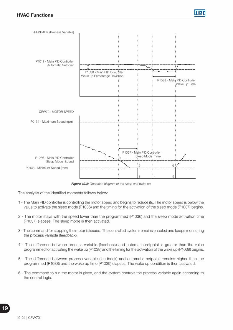
19
HVAC Functions
19-24 | CFW701
P0133 - Minimum Speed (rpm)
P0134 - Maximum Speed (rpm)
CFW701 MOTOR SPEED
1
2
3 4 5
6
P1036 - Main PID Controller Sleep Mode Speed
P1037 - Main PID Controller Sleep Mode Time
P1011 - Main PID Controller Automatic Setpoint
FEEDBACK (Process Variable)
P1038 - Main PID Controller Wake up Percentage Deviation
P1039 - Main PID Controller Wake up Time
Figure 19.3: Operation diagram of the sleep and wake up
The analysis of the identified moments follows below:
1 - The Main PID controller is controlling the motor speed and begins to reduce its. The motor speed is below the value to activate the sleep mode (P1036) and the timing for the activation of the sleep mode (P1037) begins.
2 - The motor stays with the speed lower than the programmed (P1036) and the sleep mode activation time (P1037) elapses. The sleep mode is then activated.
3 - The command for stopping the motor is issued. The controlled system remains enabled and keeps monitoring the process variable (feedback).
4 - The difference between process variable (feedback) and automatic setpoint is greater than the value programmed for activating the wake up (P1038) and the timing for the activation of the wake up (P1039) begins.
5 - The difference between process variable (feedback) and automatic setpoint remains higher than the programmed (P1038) and the wake up time (P1039) elapses. The wake up condition is then activated.
6 - The command to run the motor is given, and the system controls the process variable again according to the control logic.

HVAC Functions
19
CFW701 | 19-25
19.9 EXTERNAL PID CONTROLLER 1
This parameter group allows the user to configure the External PID controller 1 operation.
The External PID controller 1 allows controlling an external actuator to the CFW701 frequency inverter via analog output by comparing the process variable control (feedback) with the required setpoint. The process variable control is that the External PID controller 1 takes as return (feedback) of its control action being compared with the setpoint required to generate the control error. The same is read via an analog input, so you will need to configure which of the analog inputs serve as feedback for the External PID controller 1.
Is adopted the "Academic" structure for the External PID controller 1, which obeys the following equation:
u(k) = u(k-1) + Kp ∙ [(1 + Ki ∙ Ts + (Kd/Ts)) ∙ e(k) - (Kd/Ts)) ∙ e(k-1)]
where:u(k) = External PID controller 1 outputu(k-1) = Output in the last instantKp = Proportional gainKi = Integral gainKd = Derivative gainTs = Sampling timee(k) = Error in the actual instant (setpoint – feedback)e(k-1) = Error in the last instant
P1060 – External PID Controller 1 Automatic Setpoint
Adjustable Range:
-32768 to 32767 Factory Setting:
0
Properties:
Access groupsvia HMI:
HVAC
Description:
This parameter defines the value of External PID controller 1 setpoint in engineering unit when it is in automatic mode.
NOTE!This parameter is displayed as the selection in the indirect engineering unit 2 parameters (P0512 and P0513).
P1061 – External PID Controller 1 Manual Setpoint
Adjustable Range:
0.0 to 100.0 % Factory Setting:
0.0 %
Properties:
Access groupsvia HMI:
HVAC
Description:
This parameter defines the value of External PID controller 1 setpoint when it is in manual mode.

19
HVAC Functions
19-26 | CFW701
P1062 – External PID Controller 1 Feedback
Adjustable Range:
-32768 to 32767 Factory Setting:
-
Properties: RO
Access groupsvia HMI:
HVAC
Description:
This parameter indicates the actual value of External PID controller 1 feedback (process variable) in engineering unit.
NOTE!This parameter is displayed as the selection in the indirect engineering unit 2 parameters (P0512 and P0513).
P1063 – External PID Controller 1 Output
Adjustable Range:
0.0 to 100.0 % Factory Setting:
-
Properties: RO
Access groupsvia HMI:
HVAC
Description:
This parameter indicates the actual value of External PID controller 1 output.
P1064 – External PID Controller 1 Action Control
Adjustable Range:
0 = Disable PID 1 = Direct Mode2 = Reverse Mode
Factory Setting:
0
Properties:
Access groupsvia HMI:
HVAC
Description:
This parameter defines how the action control or regulation of External PID controller 1.
Table 19.11: Description of External PID controller 1 action control
P1064 Description0 It defines the External PID controller 1 will be disabled to operation.1 It defines the External PID controller 1 action control or regulation will be enabled in direct mode.2 It defines the External PID controller 1 action control or regulation will be enabled in reverse mode.

HVAC Functions
19
CFW701 | 19-27
NOTE!The External PID 1 action control should be selected to Direct Mode when to increase the value of the process variable is necessary increase the output of the External PID 1. Ex: Valve positioned in entry of water from a reservoir. For the reservoir level (process variable) increases, it is necessary that the flow rate increases, which is achieved by opening the valve.The External PID 1 action control should be selected to Reverse Mode when to increase the value of the process variable is necessary reduce the output of the External PID 1. Ex: Valve positioned in water outlet of a reservoir. For the reservoir level (process variable) increases, it is necessary that the flow rate decreases, which is achieved by closing the valve.
P1065 – External PID Controller 1 Operation Mode
Adjustable Range:
0 = Always Automatic 1 = Always Manual2 = Automatic or Manual selection via DIx and transition without bumpless3 = Automatic or Manual selection via Network and transition without bumpless4 = Automatic or Manual selection via DIx and transition with bumpless5 = Automatic or Manual selection via Network and transition with bumpless
Factory Setting:
0
Properties:
Access groupsvia HMI:
HVAC
Description:
This parameter defines how the External PID controller 1 will work.
Table 19.12: Description of External PID controller 1 operation mode
P1065 Description0 It defines the External PID controller 1 will be work always in automatic mode.1 It defines the External PID controller 1 will be work always in manual mode.
2It defines the digital input DIx programmed for Automatic / Manual will select the operation mode External PID controller 1 in automatic (0) or manual (1). It also defines the transition from automatic to manual or manual to automatic will be done without bumpless.
3It defines the bit 14 of serial control word (P0682) will select the operation mode of External PID controller 1 in automatic (0) or manual (1). It also defines the transition from automatic to manual or manual to automatic will be done without bumpless.
4It defines the digital input DIx programmed for Automatic / Manual will select the operation mode of External PID controller 1 in automatic (0) or manual (1). It also defines the transition from automatic to manual or manual to automatic will be done with bumpless.
5It defines the bit 14 of serial control word (P0682) will select the operation mode of External PID controller 1 in automatic (0) or manual (1). It also defines the transition from automatic to manual or manual to automatic will be done with bumpless.
NOTE!Bumpless transfer is making the transition from Manual to Automatic Mode or Automatic to Manual Mode without causing variation in the output of the External PID Controller 1.When the transition occurs from Manual to Automatic Mode, the output value in Manual Mode is used to start the Integral portion of the External PID Controller 1. This ensures that the output will start at this value.When the transition occurs from Automatic to Manual Mode, the output value in Automatic Mode is used as the setpoint in Manual Mode.
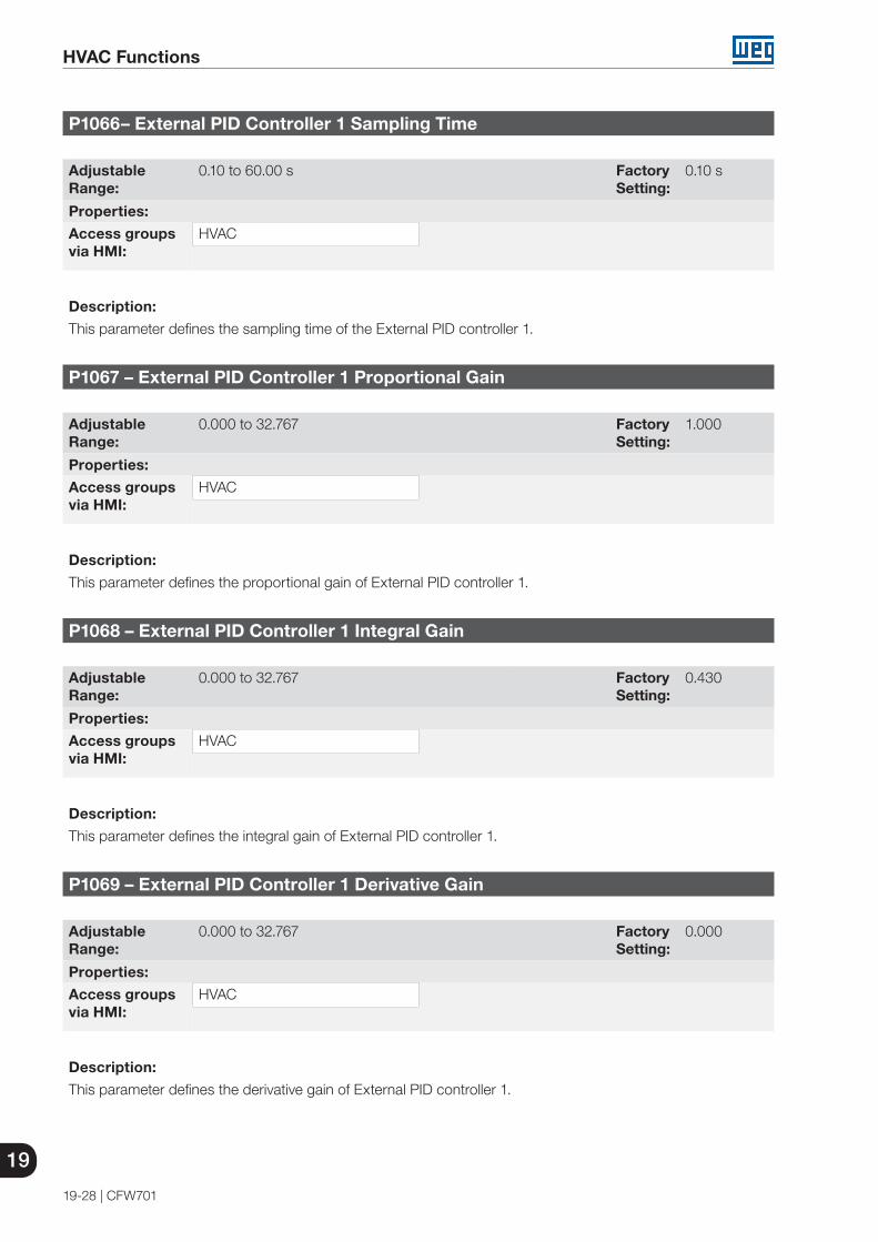
19
HVAC Functions
19-28 | CFW701
P1066– External PID Controller 1 Sampling Time
Adjustable Range:
0.10 to 60.00 s Factory Setting:
0.10 s
Properties:
Access groupsvia HMI:
HVAC
Description:
This parameter defines the sampling time of the External PID controller 1.
P1067 – External PID Controller 1 Proportional Gain
Adjustable Range:
0.000 to 32.767 Factory Setting:
1.000
Properties:
Access groupsvia HMI:
HVAC
Description:
This parameter defines the proportional gain of External PID controller 1.
P1068 – External PID Controller 1 Integral Gain
Adjustable Range:
0.000 to 32.767 Factory Setting:
0.430
Properties:
Access groupsvia HMI:
HVAC
Description:
This parameter defines the integral gain of External PID controller 1.
P1069 – External PID Controller 1 Derivative Gain
Adjustable Range:
0.000 to 32.767 Factory Setting:
0.000
Properties:
Access groupsvia HMI:
HVAC
Description:
This parameter defines the derivative gain of External PID controller 1.

HVAC Functions
19
CFW701 | 19-29
P1070 – External PID Controller 1 Output Minimum Value
Adjustable Range:
0.0 to 100.0 % Factory Setting:
0.0 %
Properties:
Access groupsvia HMI:
HVAC
Description:
This parameter defines the minimum output value of the External PID controller 1.
P1071 – External PID Controller 1 Output Maximum Value
Adjustable Range:
0.0 to 100.0 % Factory Setting:
100.0 %
Properties:
Access groupsvia HMI:
HVAC
Description:
This parameter defines the maximum output value of the External PID controller 1.
P1073 – External PID Controller 1 Feedback Minimum Level
Adjustable Range:
-32768 to 32767 Factory Setting:
0
Properties:
Access groupsvia HMI:
HVAC
Description:
This parameter defines the minimum value of the analog input sensor of the External PID controller 1 feedback for conversion into engineering unit.
NOTE!This parameter is displayed as the selection in the indirect engineering unit 2 parameters (P0512 and P0513).

19
HVAC Functions
19-30 | CFW701
P1074 – External PID Controller 1 Feedback Maximum Level
Adjustable Range:
-32768 to 32767 Factory Setting:
1000
Properties:
Access groupsvia HMI:
HVAC
Description:
This parameter defines the maximum value of the analog input sensor of the External PID controller 1 feedback for conversion into engineering unit.
NOTE!This parameter is displayed as the selection in the indirect engineering unit 2 parameters (P0512 and P0513).
P1075 – External PID Controller 1 Feedback Alarms Configuration
Adjustable Range:
0 = Disable1 = Enable and only alarm2 = Enable and generate fault (stops the motor before)
Factory Setting:
0
Properties:
Access groupsvia HMI:
HVAC
Description:
This parameter defines how the External PID controller 1 feedback alarms for low or high level will go act in the CFW701 frequency inverter.
Table 19.13: Description of External PID controller 1 feedback alarms configuration
P1075 Description0 It defines the External PID controller 1 feedback alarms for low or high level will be disabled.
1It defines the External PID controller 1 feedback alarms for low or high level will be enabled and only will generate the respective alarm message (A0786 or A0788), leaving the External PID controller 1 active.
2 It defines the External PID controller 1 feedback alarms for low or high level will be enabled and will generate the fault (F0787 or F0789) in the CFW701 frequency inverter after stopping the motor.

HVAC Functions
19
CFW701 | 19-31
P1076 – External PID Controller 1 Feedback Alarm Low Level Value
Adjustable Range:
-32768 to 32767 Factory Setting:
2
Properties:
Access groupsvia HMI:
HVAC
Description:
This parameter defines the feedback value below which is considered low level for the sensor of analog input of the External PID controller 1 feedback in engineering unit.
NOTE!This parameter is displayed as the selection in the indirect engineering unit 2 parameters (P0512 and P0513).
P1077 – External PID Controller 1 Feedback Alarm Low Level Time
Adjustable Range:
0.00 to 650.00 s Factory Setting:
5.00 s
Properties:
Access groupsvia HMI:
HVAC
Description:
This parameter defines the time on the External PID controller 1 feedback low level condition active to be generated the alarm message “A0786: Low level for External PID controller 1 feedback”. With P1075 in 2, will be generated a fault “F0787: Low level for External PID controller 1 feedback” in the CFW701 frequency inverter after stopping the motor.
NOTE!Value in 0.00 s disables the alarm detection.
P1078 – External PID Controller 1 Feedback Alarm High Level Value
Adjustable Range:
-32768 to 32767 Factory Setting:
900
Properties:
Access groupsvia HMI:
HVAC
Description:
This parameter defines the feedback value above which is considered high level for the sensor of analog input of the External PID controller 1 feedback in engineering unit.
NOTE!This parameter is displayed as the selection in the indirect engineering unit 2 parameters (P0512 and P0513).

19
HVAC Functions
19-32 | CFW701
P1079 – External PID Controller 1 Feedback Alarm High Level Time
Adjustable Range:
0.00 to 650.00 s Factory Setting:
5.00 s
Properties:
Access groupsvia HMI:
HVAC
Description:
This parameter defines the time on the External PID controller 1 feedback high level condition active to be generated the alarm message “A0788: High level for External PID controller 1 feedback”. With P1075 in 2, will be generated a fault “F0789: High level for External PID controller 1 feedback” in the CFW701 frequency inverter after stopping the motor.
NOTE!Value in 0.00 s disables the alarm detection.
19.10 EXTERNAL PID CONTROLLER 2
This parameter group allows the user to configure the External PID controller 2 operation.
The External PID controller 2 allows controlling an external actuator to the CFW701 frequency inverter via analog output by comparing the process variable control (feedback) with the required setpoint.
The process variable control is that the External PID controller 2 takes as return (feedback) of its control action being compared with the setpoint required to generate the control error. The same is read via an analog input, so you will need to configure which of the analog inputs serve as feedback for the External PID controller 2.
Is adopted the "Academic" structure for the External PID controller 2, which obeys the following equation:
u(k) = u(k-1) + Kp ∙ [(1 + Ki ∙ Ts + (Kd/Ts)) ∙ e(k) - (Kd/Ts) ∙ e(k-1)]
where:u(k) = External PID controller 2 outputu(k-1) = Output in the last instantKp = Proportional gainKi = Integral gainKd = Derivative gainTs = Sampling timee(k) = Error in the actual instant (setpoint – feedback)e(k-1) = Error in the last instant

HVAC Functions
19
CFW701 | 19-33
P1080 – External PID Controller 2 Automatic Setpoint
Adjustable Range:
-32768 to 32767 Factory Setting:
0
Properties:
Access groupsvia HMI:
HVAC
Description:
This parameter defines the value of External PID controller 2 setpoint in engineering unit when it is in automatic mode.
NOTE!This parameter is displayed as the selection in the indirect engineering unit 3 parameters (P0514 and P0515).
P1081 – External PID Controller 2 Manual Setpoint
Adjustable Range:
0.0 to 100.0 % Factory Setting:
0.0 %
Properties:
Access groupsvia HMI:
HVAC
Description:
This parameter defines the value of External PID controller 2 setpoint when it is in manual mode.
P1082 – External PID Controller 2 Feedback
Adjustable Range:
-32768 to 32767 Factory Setting:
-
Properties: RO
Access groupsvia HMI:
HVAC
Description:
This parameter indicates the actual value of External PID controller 2 feedback (process variable) in engineering unit.
NOTE!This parameter is displayed as the selection in the indirect engineering unit 3 parameters (P0514 and P0515).

19
HVAC Functions
19-34 | CFW701
P1083 – External PID Controller 2 Output
Adjustable Range:
0.0 to 100.0 % Factory Setting:
-
Properties: RO
Access groupsvia HMI:
HVAC
Description:
This parameter indicates the actual value of External PID controller 2 output.
P1084 – External PID Controller 2 Action Control
Adjustable Range:
0 = Disable PID 1 = Direct Mode2 = Reverse Mode
Factory Setting:
0
Properties:
Access groupsvia HMI:
HVAC
Description:
This parameter defines how the action control or regulation of External PID controller 2.
Table 19.14: Description of External PID controller 2 action control
P1084 Description0 It defines the External PID controller 2 will be disabled to operation.1 It defines the External PID controller 2 action control or regulation will be enabled in direct mode.2 It defines the External PID controller 2 action control or regulation will be enabled in reverse mode.
NOTE!The External PID 2 action control should be selected to Direct Mode when to increase the value of the process variable is necessary increase the output of the External PID 2. Ex: Valve positioned in entry of water from a reservoir. For the reservoir level (process variable) increases, it is necessary that the flow rate increases, which is achieved by opening the valve.The External PID 2 action control should be selected to Reverse Mode when to increase the value of the process variable is necessary reduce the output of the External PID 2. Ex: Valve positioned in water outlet of a reservoir. For the reservoir level (process variable) increases, it is necessary that the flow rate decreases, which is achieved by closing the valve.
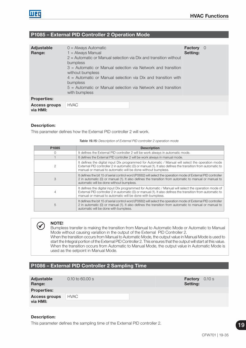
HVAC Functions
19
CFW701 | 19-35
P1085 – External PID Controller 2 Operation Mode
Adjustable Range:
0 = Always Automatic 1 = Always Manual2 = Automatic or Manual selection via DIx and transition without bumpless3 = Automatic or Manual selection via Network and transition without bumpless4 = Automatic or Manual selection via DIx and transition with bumpless5 = Automatic or Manual selection via Network and transition with bumpless
Factory Setting:
0
Properties:
Access groupsvia HMI:
HVAC
Description:
This parameter defines how the External PID controller 2 will work.
Table 19.15: Description of External PID controller 2 operation mode
P1085 Description0 It defines the External PID controller 2 will be work always in automatic mode.1 It defines the External PID controller 2 will be work always in manual mode.
2It defines the digital input DIx programmed for Automatic / Manual will select the operation mode External PID controller 2 in automatic (0) or manual (1). It also defines the transition from automatic to manual or manual to automatic will be done without bumpless.
3It defines the bit 15 of serial control word (P0682) will select the operation mode of External PID controller 2 in automatic (0) or manual (1). It also defines the transition from automatic to manual or manual to automatic will be done without bumpless.
4It defines the digital input DIx programmed for Automatic / Manual will select the operation mode of External PID controller 2 in automatic (0) or manual (1). It also defines the transition from automatic to manual or manual to automatic will be done with bumpless.
5It defines the bit 15 of serial control word (P0682) will select the operation mode of External PID controller 2 in automatic (0) or manual (1). It also defines the transition from automatic to manual or manual to automatic will be done with bumpless.
NOTE!Bumpless transfer is making the transition from Manual to Automatic Mode or Automatic to Manual Mode without causing variation in the output of the External PID Controller 2.When the transition occurs from Manual to Automatic Mode, the output value in Manual Mode is used to start the Integral portion of the External PID Controller 2. This ensures that the output will start at this value.When the transition occurs from Automatic to Manual Mode, the output value in Automatic Mode is used as the setpoint in Manual Mode.
P1086 – External PID Controller 2 Sampling Time
Adjustable Range:
0.10 to 60.00 s Factory Setting:
0.10 s
Properties:
Access groupsvia HMI:
HVAC
Description:
This parameter defines the sampling time of the External PID controller 2.

19
HVAC Functions
19-36 | CFW701
P1087 – External PID Controller 2 Proportional Gain
Adjustable Range:
0.000 to 32.767 Factory Setting:
1.000
Properties:
Access groupsvia HMI:
HVAC
Description:
This parameter defines the proportional gain of External PID controller 2.
P1088 – External PID Controller 2 Integral Gain
Adjustable Range:
0.000 to 32.767 Factory Setting:
0.430
Properties:
Access groupsvia HMI:
HVAC
Description:
This parameter defines the integral gain of External PID controller 2.
P1089 – External PID Controller 2 Derivative Gain
Adjustable Range:
0.000 to 32.767 Factory Setting:
0.000
Properties:
Access groupsvia HMI:
HVAC
Description:
This parameter defines the derivative gain of External PID controller 2.
P1090 – External PID Controller 2 Output Minimum Value
Adjustable Range:
0.0 to 100.0 % Factory Setting:
0.0 %
Properties:
Access groupsvia HMI:
HVAC
Description:
This parameter defines the minimum output value of the External PID controller 2.

HVAC Functions
19
CFW701 | 19-37
P1091 – External PID Controller 2 Output Maximum Value
Adjustable Range:
0.0 to 100.0 % Factory Setting:
100.0 %
Properties:
Access groupsvia HMI:
HVAC
Description:
This parameter defines the maximum output value of the External PID controller 2.
P1093 – External PID Controller 2 Feedback Minimum Level
Adjustable Range:
-32768 to 32767 Factory Setting:
0
Properties:
Access groupsvia HMI:
HVAC
Description:
This parameter defines the minimum value of the analog input sensor of the External PID controller 2 feedback for conversion into engineering unit.
NOTE!This parameter is displayed as the selection in the indirect engineering unit 3 parameters (P0514 and P0515).
P1094 – External PID Controller 2 Feedback Maximum Level
Adjustable Range:
-32768 to 32767 Factory Setting:
1000
Properties:
Access groupsvia HMI:
HVAC
Description:
This parameter defines the maximum value of the analog input sensor of the External PID controller 2 feedback for conversion into engineering unit.
NOTE!This parameter is displayed as the selection in the indirect engineering unit 3 parameters (P0514 and P0515).

19
HVAC Functions
19-38 | CFW701
P1095 – External PID Controller 2 Feedback Alarms Configuration
Adjustable Range:
0 = Disable1 = Enable and only alarm2 = Enable and generate fault (stops the motor before)
Factory Setting:
0
Properties:
Access groupsvia HMI:
HVAC
Description:
This parameter defines how the External PID controller 2 feedback alarms for low or high level will go act in the CFW701 frequency inverter.
Table 19.16: Description of External PID controller 2 feedback alarms configuration
P1095 Description0 It defines the External PID controller 2 feedback alarms for low or high level will be disabled.
1It defines the External PID controller 2 feedback alarms for low or high level will be enabled and only will generate the respective alarm message (A0796 or A0798), leaving the External PID controller 2 active and controlling the motor driven by CFW701.
2 It defines the External PID controller 2 feedback alarms for low or high level will be enabled and will generate the fault (F0797 or F0799) in the CFW701 frequency inverter after stopping the motor.
P1096 – External PID Controller 2 Feedback Alarm Low Level Value
Adjustable Range:
-32768 to 32767 Factory Setting:
2
Properties:
Access groupsvia HMI:
HVAC
Description:
This parameter defines the feedback value below which is considered low level for the sensor of analog input of the External PID controller 2 feedback in engineering unit.
NOTE!This parameter is displayed as the selection in the indirect engineering unit 3 parameters (P0514 and P0515).
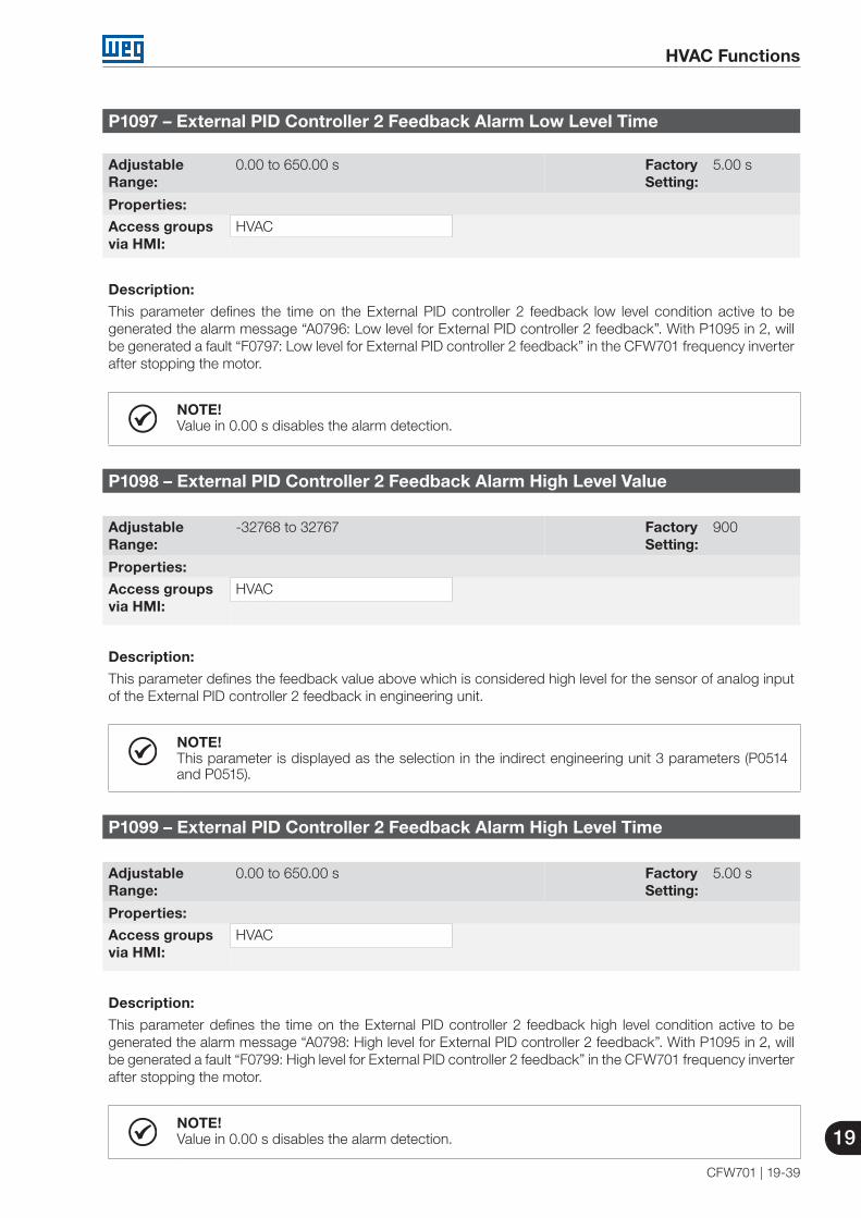
HVAC Functions
19
CFW701 | 19-39
P1097 – External PID Controller 2 Feedback Alarm Low Level Time
Adjustable Range:
0.00 to 650.00 s Factory Setting:
5.00 s
Properties:
Access groupsvia HMI:
HVAC
Description:
This parameter defines the time on the External PID controller 2 feedback low level condition active to be generated the alarm message “A0796: Low level for External PID controller 2 feedback”. With P1095 in 2, will be generated a fault “F0797: Low level for External PID controller 2 feedback” in the CFW701 frequency inverter after stopping the motor.
NOTE!Value in 0.00 s disables the alarm detection.
P1098 – External PID Controller 2 Feedback Alarm High Level Value
Adjustable Range:
-32768 to 32767 Factory Setting:
900
Properties:
Access groupsvia HMI:
HVAC
Description:
This parameter defines the feedback value above which is considered high level for the sensor of analog input of the External PID controller 2 feedback in engineering unit.
NOTE!This parameter is displayed as the selection in the indirect engineering unit 3 parameters (P0514 and P0515).
P1099 – External PID Controller 2 Feedback Alarm High Level Time
Adjustable Range:
0.00 to 650.00 s Factory Setting:
5.00 s
Properties:
Access groupsvia HMI:
HVAC
Description:
This parameter defines the time on the External PID controller 2 feedback high level condition active to be generated the alarm message “A0798: High level for External PID controller 2 feedback”. With P1095 in 2, will be generated a fault “F0799: High level for External PID controller 2 feedback” in the CFW701 frequency inverter after stopping the motor.
NOTE!Value in 0.00 s disables the alarm detection.

19
HVAC Functions
19-40 | CFW701
19.11 HVAC FUNCTIONS LOGICAL STATUS
This parameter group allows the user to monitoring the status of HVAC functions.
P1040 – HVAC Functions Logical Status
Adjustable Range:
0000h to FFFFh Factory Setting:
-
Properties: RO
Access groupsvia HMI:
HVAC
Description:
This parameter allows the user to monitoring the logical status of HVAC functions. Each bit represents a specific status.
Table 19.17: Description of HVAC function logical status
Bits 15 to 10 9 8 7 6 5 4 3 2 1 0
Func
tion
Res
erve
d
Aut
omat
ic /
Man
ual
for
Ext
erna
l PID
C
ontr
olle
r 2
Aut
omat
ic /
Man
ual
for
Ext
erna
l PID
C
ontr
olle
r 1
Sle
ep M
ode
Aut
omat
ic /
Man
ual
for
Mai
n P
ID
Con
trol
ler
Filte
r M
aint
enan
ce
Bro
ken
Bel
t
Dry
Pum
p
Sho
rt C
ycle
P
rote
ctio
n
Byp
ass
Mod
e
Fire
Mod
e
Bits ValuesBit 0
Fire Mode0: The inverter is not in Fire Mode.1: The inverter is operated in Fire Mode.
Bit 1Bypass Mode
0: The inverter is not in Bypass Mode.1: The inverter is operated in Bypass Mode.
Bit 2Short Cycle Protection
0: Short cycle protection is not active.1: Short cycle protection is active.
Bit 3Dry Pump
0: Dry pump condition was not detected.1: Dry pump condition was detected.
Bit 4Broken Belt
0: Broken belt condition was not detected.1: Broken belt condition was detected.
Bit 5Filter Maintenance
0: Filter maintenance alarm was not detected.1: Filter maintenance alarm was detected.
Bit 6Automatic / Manual for
Main PID Controller
0: Main PID controller in automatic mode.1: Main PID controller in manual mode.
Bit 7Sleep Mode
0: The inverter is not in Sleep Mode.1: The inverter is operated in Sleep Mode.
Bit 8Automatic / Manual for
External PID Controller 1
0: External PID controller 1 in automatic mode.1: External PID controller 1 in manual mode.
Bit 9Automatic / Manual for
External PID Controller 2
0: External PID controller 2 in automatic mode.1: External PID controller 2 in manual mode.
Bits 10 to 15 Reserved.
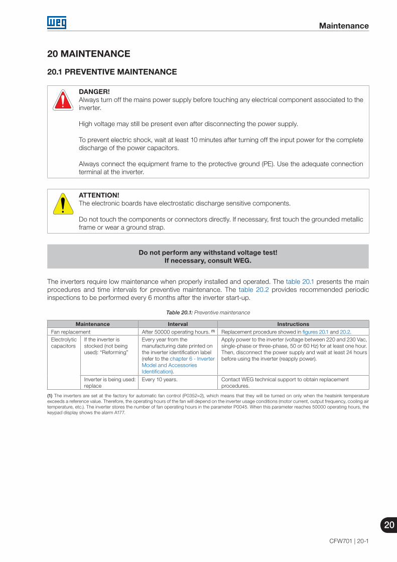
Maintenance
20
CFW701 | 20-1
20 MAINTENANCE
20.1 PREVENTIVE MAINTENANCE
DANGER!Always turn off the mains power supply before touching any electrical component associated to the inverter. High voltage may still be present even after disconnecting the power supply.
To prevent electric shock, wait at least 10 minutes after turning off the input power for the complete discharge of the power capacitors.
Always connect the equipment frame to the protective ground (PE). Use the adequate connection terminal at the inverter.
ATTENTION!The electronic boards have electrostatic discharge sensitive components.
Do not touch the components or connectors directly. If necessary, first touch the grounded metallicframe or wear a ground strap.
Do not perform any withstand voltage test!
If necessary, consult WEG.
The inverters require low maintenance when properly installed and operated. The table 20.1 presents the main procedures and time intervals for preventive maintenance. The table 20.2 provides recommended periodic inspections to be performed every 6 months after the inverter start-up.
Table 20.1: Preventive maintenance
Maintenance Interval InstructionsFan replacement After 50000 operating hours. (1) Replacement procedure showed in figures 20.1 and 20.2. Electrolytic capacitors
If the inverter is stocked (not being used): “Reforming”
Every year from the manufacturing date printed on the inverter identification label (refer to the chapter 6 - Inverter Model and Accessories Identification).
Apply power to the inverter (voltage between 220 and 230 Vac, single-phase or three-phase, 50 or 60 Hz) for at least one hour. Then, disconnect the power supply and wait at least 24 hours before using the inverter (reapply power).
Inverter is being used: replace
Every 10 years. Contact WEG technical support to obtain replacement procedures.
(1) The inverters are set at the factory for automatic fan control (P0352=2), which means that they will be turned on only when the heatsink temperature exceeds a reference value. Therefore, the operating hours of the fan will depend on the inverter usage conditions (motor current, output frequency, cooling air temperature, etc.). The inverter stores the number of fan operating hours in the parameter P0045. When this parameter reaches 50000 operating hours, the keypad display shows the alarm A177.

20
Maintenance
20-2 | CFW701
Table 20.2: Recommended periodic inspections - Every 6 months
Component Abnormality Corrective Action Terminals, connectors Loose screws Tighten
Loose connectors Fans / Cooling system Dirty fans Cleaning
Abnormal acoustic noise Replace the fan. Refer to the figures 20.1 and 20.2. Check the fan connections.
Blocked fan Abnormal vibration Dust in the cabinet air filter Cleaning or replacement
Printed circuit boards Accumulation of dust, oil, humidity, etc. Cleaning Odor Replacement
Power module / Power connections
Accumulation of dust, oil, humidity, etc. Cleaning Loose connection screws Tighten
DC bus capacitors (DC link)
Discoloration / odor / electrolyte leakage Replacement Expanded or broken safety valve Frame expansion
Power resistors Discoloration Replacement Odor
Heatsink Dust accumulation Cleaning Dirty
20.2 CLEANING INSTRUCTIONS
When it is necessary to clean the inverter, follow the instructions below:
Ventilation system:
Disconnect the inverter power supply and wait at least 10 minutes.
Remove the dust from the cooling air inlet by using a soft brush or a flannel.
Remove the dust from the heatsink fins and from the fan blades by using compressed air.
Electronic boards:
Disconnect the inverter power supply and wait at least 10 minutes.
Remove the dust from the electronic board by using an anti-static brush or an ion air gun (Charges Burtes Ion Gun - reference A6030-6DESCO).
If necessary, remove the boards from the inverter.
Always wear a ground strap.

Maintenance
20
CFW701 | 20-3
1 2 3
Releasing the latches of the fan cover
Fan removal Cable disconnection
(a) Models up to 105 A
1 2 3
Fan grill screws removal Fan removal Cable disconnection
(b) Models 142 A, 180 A and 211 A
Figure 20.1 (a) and (b): Fan removal
1 2
Cable connection Fan fitting
(a) Models up to 105 A
1 2
Cable connection Fan and grill fastening
(b) Models 142 A, 180 A and 211 A
Figure 20.2 (a) and (b): Fan installation