cg-prc008-e4 - engineer.trane.com · chilled-water flow capability ... systems reliability. -...
TRANSCRIPT
CGWH Packaged Water-cooledliquid chillerCCUH Condenserless liquid chillerSizes: 115 - 120 - 125 - 225 - 230 - 235 -240 - 250
Indoor liquid chiller
CG-PRC008-E4

CG-PRC008-E42

Contents
3CG-PRC008-E4
Introduction 4
Features and benefits 5
Options description 9
Applications consideration 10
Control 15
Selection Procedures 21
Performances 23
General data 26
Hydraulic data 28
Sound performances 29
Units schematics 30
The CGWH/CCUH chillers rangeequipped with Scroll compressorscombines the latest technologiesavailable to offer an optimumanswer for today’s air-conditioningand process cooling applications:- Scroll compressor technology,
with high performance, limitedmaintenance and longer life timedesign
- Latest generation of Tranecontrols, with user friendlygraphical interface and integralauto-adaptive to guaranteemaximum dependability
- High efficiency heat exchangers,allowing significant savings onoperating cost
- Integrated hydraulic packages, toshorten installation andcommissioning time.
Introduction
CG-PRC008-E44

Industry leading
performance and flexibility
for design engineers
The next generation: designed for
You
The third generation of thesuccessful indoor Scroll compressorproduct range has several benefitsover the previous design. Yoursuggestions led to theimprovements we haveincorporated, including:- Higher full-load energy efficiency
for lower operating and life-cyclecosts
- CH530 controls, with touch-screendisplay and LonTalk® capability
- Less sensitivity to condenser-water temperatures, alleviatingconcerns based on start-uptemperatures
- Lighter weight for easier and lessexpensive handling andinstallation.
Applications: Operation and control
advantages for any application
The Scroll compressor technology,with fewer moving parts, lessrotating mass and less internalfriction, associated with CH530 andAdaptive Controls™, allow theCGWH/CCUH range to be used in awide variety of applicationsincluding:- Comfort cooling: designed for
reliability, energy efficiency, andsystem-design optimisation,whether the heat is rejected via anopen cooling tower or a closedloop device (dry-cooler)
- Industrial process cooling: reliableoperation with tight control oftemperatures
- Ice/thermal storage- Heat recovery- Low-temperature process cooling.
System design and control: Greater
application flexibility for increased
savings
First-cost and operating costminimising system-design conceptsare catching on as their validity isproven through applications. Thesedesigns can provide lowerequipment costs and loweroperating costs than those possiblewith the traditional design methodsand past chiller technologies. Theconcepts of the CGWH/CCUH rangeinclude:- Heat exchangers with reduced
water pressure drops and widerwater flow/delta capability
- Thermal storage capability- Variable primary (evaporator)
chilled-water flow capability- Series evaporator and/or
condenser arrangementsThe CGWH/CCUH range is designedfor a wide range of applications andis especially suited for the dynamicsof these system saving job designs.The dynamic benefits include:- Efficient lift capability- Tight temperature control.
CH530 controls mean that theCGWH/CCUH series chillers canmaintain tight leaving-watertemperature control in almost anyapplication. These benefits fitespecially well with the systemdesign savings ideas listed above.As the compressor reaches theoperating temperatures for theapplication, the controls, make sureyou have total temperature control,even with chilled-water flow and/orload changes.
Features and benefits
5CG-PRC008-E4
Sound: Lower sound levels through
compressor and chiller design
Trane has a proven track record ofcontinuously improving the soundlevels of water chillers. With theCGWH/CCUH range Trane hasdesigned a fully hermetic cabinetdesign which minimises soundradiation in the neighbourhood ofthe unit. The space around thechiller can be utilised withoutrequirement of additional soundinsulation. Only the sound producedby the remote condenser fans canbe perceived in the surrounding ofthe installation, the sound ofcompressor is attenuated by thebuilding structure.
Minimised job time for
contractors through design
and testing
Ease of installation
- Footprint: Central to the design ofany project is the operatingenvelope of the chiller. With this inmind, Trane builds the chillers tomake the most efficient use of theavailable installation space. Thecompact CGWH/CCUH rangechiller is an excellent choice forany retrofit or replacement job. Itis smaller than most chillers itmight replace, and easier to fitinto existing buildings. All units fitthrough a standard single door.
- Weight: Furthermore, thedecreased weight reduces therequirements for lifting, rigging,and installation. Installation timeand effort are reduced whendealing with a significantly smallerand lighter unit.
- Commissioning: Water cooledunits (CGWH) come from factoryfully charged with refrigerant andoil, condenserless version (CCUH)with holding charge. Extensivefactory testing helps ensuretrouble-free start-up, resulting inlower installation costs and fasterjob completion.
The Integrated comfort system
The water-cooled CGWH/CCUHchiller, with the CH530, makes apowerful combination with theTrane Tracer Summit BuildingManagement System to becomepart of a Trane Integrated Comfortsystem (ICS). An Integrated Comfortsystem is a building comfort systemcomposed of Trane HVACequipment, integral unit controllers,and building management. It is alldesigned and commissioned withTrane application expertise toprovide comfort, efficiency, andreliability, as well as single-sourcewarranty and service. Whether youare replacing a chiller or adding oneto any centrally controlled plant, theTracer CH530 chiller controller offersa wide range of interface options.Its ability to communicate withother systems using industry-standard control signals allows youto upgrade the control of yourchiller plant regardless of yourcurrent control system.
Features and benefits
CG-PRC008-E46

Single-source responsibility
A wide range of products designedfor complete compatibility areavailable with the CGWH/CCUHscroll chillers. Your entire buildingcomfort system can be completedusing components from Trane.
The added value of applications
expertise
You get a quality chiller, properlyselected and applied in a properlydesigned system. That means acomfort system that works, the firsttime!
Reduced total life cycle
operating cost for building
owner.
Energy efficiency: Reduced annual
operating expenses
The CGWH/CCUH chiller design hasbeen optimized in order to achieverecord efficiency levels. With theCH530 chiller control module,control over the chilled-watertemperature is increased,simultaneously reducing annualoperating costs. CGWH/CCUHchillers offer superior full-loadperformance and optimised part-load performance.
Reduced maintenance: Less time
and money every year
The only recommendedmaintenance for a CGWH/CCUHchiller is an annual oil analysis. Thehermetic design allows thecompressor to be driven by a zero-maintenance motor. The installationof strainers upstream theevaporator and condenser (Option)eliminates the need for cleaning theheat exchangers tubes. TheAdaptive Control™ microprocessoralso helps reduce unnecessarymaintenance by monitoring,protecting, and taking correctiveaction so that the chiller stays on-line when you need it the most.Service calls for nuisance trip-outsare virtually eliminated.
Reliability
Trane has designed theCGWH/CCUH chiller range to be aleader in reliability for allapplications:- Simple design with 64 percent
fewer parts than equal capacityreciprocating compressor.
- Advanced microelectronics protectboth compressor and motor fromtypical electrical fault conditions.
- Scroll compressors have less thana third the torque variations of areciprocating compressor.
- Years of laboratory testing haveoptimised compressor and chillersystems reliability.
- Water-cooled scroll chillers arefactory tested.
Comfort cooling: designed for
reliability, energy efficiency, and
system design optimisation
Most comfort-cooling applicationsconsider reliability and energyefficiency above all else in thedesign requirements. With provenreliability and high chiller efficiency,the CGWH/CCUH chillers areperfectly suited for theseapplications.
Industrial process cooling / Low
temperature process: Reliable
operation with tight control of
temperatures
The Trane CGWH/CCUH chillershave the proven reliability requiredto keep the process running,eliminating concerns for chiller andresulting process downtime. Thechiller matches systemrequirements and rapidly adjusts tomatch the changes seen by mostprocesses.
Features and benefits
7CG-PRC008-E4

Ice / thermal storage
The Trane CGWH/CCUH chillers canbe used in partial or full thermal-storage applications because oftheir excellent compressor lift(operating temperature range)capability. High reliability and lowmaintenance means thermalstorage applications are possiblewithout a full-timeoperation/maintenance staff, andTrane Integrated Comfort SystemControls can notify a computer orpager of any system issues.
Heat recovery
The Trane CGWH chillerscompressor lift capabilities also playwell in heat recovery, or just high-temperature condenserapplications. Building energy savinginitiatives such as using condenserwater for reheat (dehumidification),preheating boiler water, andproviding domestic hot water arecompatible with its temperaturecapabilities.
Easy serviceability
Trane CGWH/CCUH chillers aredesigned with service personnel inmind. All major components arereplaceable without complete unitdisassembly. Plus, CH530 providesdiagnostic capability to aid servicepersonnel in analysing problems.Therefore, in case a problem doesoccur, the chiller can be up andrunning in a shorter period of time.
Features and benefits
CG-PRC008-E48

Hydraulic pump control:
• Single or dual pump contactor.
Hot water control
This option allows the control of theunit capacity based on the leavingcondenser water temperature toprovide heat recovery capability.
Phase protection device
Inhibits operation of chiller in caseof phase reversal
Setpoint and temperature offset
and display card
Allows to offset chilled watersetpoint temperature based oneither ouside air, chilled waterreturn or zone temperature andprovides inlet/outlet condenserwater temperature information.
High Efficiency Option
This option provides oversized heatexchangers to allow the unit to bemore energy efficient.
Ice Making
The unit controls are factory set tohandle ice making for thermalstorage applications.
Communication Interface
Permits bi-directionalcommunication to the TraneIntegrated Comfort™ system andprovides the LonMark® chiller profileinput/outputs for use with a genericBAS (Building Automation System)
Low Noise Version
The unit is equipped withcompressor sound jackets.
Pressure Gauges
A set of two pressure gauges perrefrigerant circuit, one for lowpressure and one for high pressure.
Options description
9CG-PRC008-E4

Optimum performance of CGWHand CCUH units will be achievedonly if proper application guidelinesare followed.Where the application varies fromthe guidelines presented, it shouldbe reviewed with your local Tranesales engineer.
Unit sizing
Unit capacities are listed in the“Performance Data” section.Intentionally oversizing a unit toassure adequate capacity is notrecommended. Erratic systemoperation and excessivecompressor cycling are often adirect result of an oversized unit. Inaddition, an oversized unit isusually more expensive topurchase, install and operate. Ifoversizing is desired, consider usingtwo units.
Foundations
A special foundation is not required,provided the floor is flat, level andstrong enough to support the unit'sweight (see "General data" tables).
Applications consideration
CG-PRC008-E410
Table 1 - Standard Operating Enveloppe - See performance data for specific informations.
CGWH CCUH
R407C R407C
Min. leaving water temperature CDS +20°C +30°CMin. Sat discharge temperature CDS
(Dew point)
Max. leaving water temperature CDS +50°C +55°CMax. Sat discharge temperature CDS
(Dew point)
Min. leaving water temperature EVP -12°C
Max. leaving water temperature EVP +12°C
Limitation HP dans les tableaux = 24.5bar (Limitation Module 23 +/- 1 bar / Pressostat HP = 26 bar ).
Limitation température de refoulement dans les tableaux = 130°C

Applications consideration
11CG-PRC008-E4
Ground isolators
4 isolators are supplied as standard.They will protect the unit from anycontact with the ground.
Water drain
Ensure that near the unit is a largeenough drain to evacuate the waterwhen from the system emptying theunit for shutdown or repair.
Water connection
Water connections are threaded ISOR7 type, location and diameter areindicated on the submittalsavailable on request.
Minimum water volume
The minimum recommended watervolume depends on the type ofapplication.
If necessary, provide a buffer tank.The control and safety devices areonly certain to operate correctly ifthe system's water volume issufficient.
Water treatment
The use of untreated or improperlytreated water in chillers may resultin scaling, erosion, corrosion oralgae. It is recommended that theservices of a qualified water-treatment specialist be obtained todetermine what water treatment, ifany, is advisable. Trane assumes noresponsibilty for the results ofuntreated, or improperly treatedwater
Flow rate limits
The minimum and maximum flowrates are indicated in the "Hydraulicdata" charts section. Too low a flowrate may cause freezing of theevaporator. Too high a flow ratemay cause erosion of theevaporator and very substantialpressure losses.
Table 2 - Minimum water loop
This table is estimated with - Condenser : Water 30°/35°C- Evaporator : Water 12°/7°C- Dead Band of 3°C
This table is estimated with - Condensing temp : 45°C with sub cooling 5°C- Evaporator : Water 12°/7°C- Dead Band of 3°C
Sizes 115 120 125 225 230 235 240 250
CCUH ChillersData
Cooling Capacity 51 kW 64 kW 77 kW 90 kW 102 kW 115 kW 127 kW 153 kW
Biggest step 50% 60% 50% 42% 38% 34% 30% 25%
Biggest step 26 kW 38 kW 38 kW 38 kW 39 kW 39 kW 38 kW 38 kW
Minimum water loop forcomfort 244 l 367 l 367 l 363 l 371 l 374 l 365 l 366 l
Sizes 115 120 125 225 230 235 240 250
CGWHChillers Data
Cooling Capacity 51 kW 64 kW 77 kW 91 kW 103 kW 116 kW 127 kW 155 kW
Biggest step 50% 60% 50% 42% 38% 34% 30% 25%
Biggest step 26 kW 38 kW 39 kW 38 kW 39 kW 39 kW 38 kW 39 kW
Minimum water loop forcomfort 244 l 368 l 368 l 365 l 375 l 377 l 365 l 371 l

Applications consideration
CG-PRC008-E412
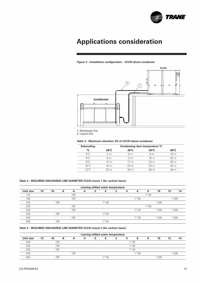
Split systems piping
recommendations
Maximum distances and refrigerantline diameters between units mustbe checked according to theconfiguration and system operatingconditions (Chilled watertemperature and subcooling). Tables3 to 7 provide the maximumacceptable height according tosubcooling available andrecommended diameters fordischarge liquid lines.
Figure 1 - Installation configuration - CCUH and condenser at the same level
1: Discharge line2: Liquid line
Figure 2 - Installation configuration - CCUH below condenser
1: Discharge line2: Liquid line
condenser
condenser
CCUH
CCUH
Applications consideration
13CG-PRC008-E4
Figure 3 - Installation configuration - CCUH above condenser
1: Discharge line2: Liquid line
Table 3 - Maximum elevation (H) of CCUH above condenser
Subcooling Condensing dew temperature °C
°C 20°C 35°C 50°C 65°C
4°C 4 m 6 m 8 m 10 m6°C 8 m 12 m 16 m 20 m8°C 12 m 17 m 23 m 30 m10°C 16 m 23 m 30 m 40 m12°C 20 m 28 m 38 m 49 m
H
Table 4 - REQUIRED DISCHARGE LINE DIAMETER CCUH circuit 1 (for vertical risers)
Table 5 - REQUIRED DISCHARGE LINE DIAMETER CCUH circuit 2 (for vertical risers)
Leaving chilled water temperature
Unit size -12 -10 -8 -6 -4 -2 0 2 4 6 8 10 12 14
225 7/8" 1"1/8230 7/8" 1"1/8235 7/8" 1"1/8240 7/8" 1"1/8 1"3/8250 7/8" 1"1/8 1"3/8
Leaving chilled water temperature
Unit size -12 -10 -8 -6 -4 -2 0 2 4 6 8 10 12 14
115 7/8" 1"1/8120 7/8" 1"1/8 1"3/8125 7/8" 1"1/8 1"3/8225 7/8" 1"1/8230 7/8" 1"1/8 1"3/8 1"3/8235 7/8" 1"1/8240 7/8" 1"1/8 1"3/8 1"3/8250 7/8" 1"1/8
condenser
CCUH
Applications consideration
CG-PRC008-E414
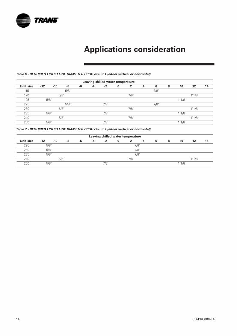
Table 6 - REQUIRED LIQUID LINE DIAMETER CCUH circuit 1 (either vertical or horizontal)
Table 7 - REQUIRED LIQUID LINE DIAMETER CCUH circuit 2 (either vertical or horizontal)
Leaving chilled water temperature
Unit size -12 -10 -8 -6 -4 -2 0 2 4 6 8 10 12 14
225 5/8" 7/8"230 5/8" 7/8"235 5/8" 7/8"240 5/8" 7/8" 1"1/8250 5/8" 7/8" 1"1/8
Leaving chilled water temperature
Unit size -12 -10 -8 -6 -4 -2 0 2 4 6 8 10 12 14
115 5/8" 7/8"120 5/8" 7/8" 1"1/8125 5/8" 1"1/8225 5/8" 7/8" 7/8"230 5/8" 7/8" 1"1/8235 5/8" 7/8" 1"1/8240 5/8" 7/8" 1"1/8250 5/8" 7/8" 1"1/8
Control
15CG-PRC008-E4
Safety Controls
A centralized microcomputer offersa higher level of machineprotection. Because the safetycontrols are smarter, they limitcompressor operation in order toavoid compressor or evaporatorfailures, thereby minimizingnuisance shutdowns. Tracer™Chiller Controls directly senses thecontrol variables that govern theoperation of the chiller: evaporatorpressure, condenser pressure. Whenany one of these variablesapproaches a limit condition atwhich the unit may be damaged orshut down on a safety, Tracer ChillerControls takes corrective action toavoid shutdown and keep the chilleroperating. It does this throughcombined actions of compressorstaging and pump staging. It hasalso the capability to control theremote condenser fan staging forcondenserless unit (CCUH). TracerChiller Controls optimizes totalchiller power consumption duringnormal operating conditions. Duringabnormal operating conditions, themicroprocessor will continue tooptimize chiller performance bytaking the corrective actionnecessary to avoid shutdown. Thiskeeps cooling capacity availableuntil the problem can be solved.Whenever possible, the chiller isallowed to perform its function:make chilled water. In addition,microcomputer controls allow formore types of protection, like winterfreeze protection; the safety controlshelp keep the building or processrunning and out of trouble.
Stand-alone controls
Interfacing to stand-alone units isvery simple: only a remoteauto/stop for scheduling is requiredfor unit operation. Signals from thechilled-water pump contactorauxiliary, or a flow switch, are wiredto the chilled-water flow interlock.Signals from a time clock or someother remote device are wired tothe external auto/stop input.
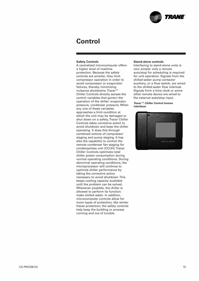
Tracer™ Chiller Control human
interfaces
Standard Features External
Auto/Stop
A job-site-provided contact closurewill turn the unit on and off.
Chilled Waterflow Interlock
Unit is equipped with a water flowcontrol, it will allow unit operation ifa load exists. This feature will allowthe unit to run in conjunction withthe pump system.
External Interlock
A job-site-provided contact openingwired to this input will turn the unitoff and require a manual reset ofthe unit microcomputer. This closureis typically triggered by a job-site-provided system such as a firealarm.
Chilled Water Pump Control
(Option)
Unit controls provide an output tocontrol the chilled-water pump(s).One contact closure to the chiller isall that is required to initiate thechilled-water system.
Alarm Indication Contacts
Four factory-installed contacts withthe following preset defaultassignments:
• Alarm • Chiller running • Maximum capacity • Chiller limit.
Additional Features that May Be
Added (require some optional
factory-installed hardware)
• Ice-making card • Tracer communication card • Chilled water and remote current
limit set point card (note: allwiring outside the unit issupplied by the contractor).
Control
CG-PRC008-E416
Control
17CG-PRC008-E4
Easy Interface to a Generic
Building Management
System Controlling the Indoor CGWH/CCUHchillers with building managementsystems is state-of-the-art, yetsimple with either:- the LonTalk Communications
Interface for Chillers (LCI-C) - or Generic Building Management
System Hardwire Points.
Simple Interface with Other Control
Systems
Microcomputer controls affordsimple interface with other controlsystems, such as time clocks,building automation systems, andice storage systems. This meansyou have the flexibility to meet jobrequirements while not having tolearn a complicated control system.This setup has the same standardfeatures as a stand-alone waterchiller, with the possibility of havingadditional optional features.
What are LonTalk, Echelon,
and LonMark? LonTalk is a communicationsprotocol developed by the EchelonCorporation. The LonMarkassociation develops controlprofiles using the LonTalkcommunication protocol. LonTalk isa unit level communicationsprotocol, unlike BACNet used at thesystem level.
LonTalk Communications Interface
for Chillers (LCI-C)
LonTalk Communications Interfacefor Chillers (LCI-C) provides ageneric automation system with theLonMark chiller profileinputs/outputs. The inputs/outputsinclude both mandatory andoptional network variables. Note:LonMark network variable namesare in parentheses when differentfrom chiller naming convention.
Chiller Inputs:
• Chiller Enable/Disable• Chilled Liquid Setpoint (Cool or
hot Setpoint)• Ice Making (Chiller Mode)
Chiller Enable/Disable
Allows for chiller to be started orstopped depending on if certainoperating conditions are met.
Chilled Liquid Setpoint
Allows for the external settingindependent of the front panelsetpoint to adjust the leaving watertemperature setpoint.
Hot Liquid Setpoint
Allows for the external settingindependent of the front panelsetpoint to adjust the leaving watertemperature setpoint from thecondenser.
Ice Making
Provides interface with ice makingcontrol systems.

Chiller Outputs:
• On/Off Active Setpoint • Leaving Chilled Water
Temperature • Entering Chilled Water
Temperature • Leaving Hot Water
Temperature• Entering Hot Water
Temperature• Alarm Descriptor • Chiller Status
On/Off
Indicates the current state of thechiller
Active Setpoint
Indicates the current value of theleaving water temperature setpoint
Leaving Chilled Water Temperature
Provides the current leaving watertemperature
Entering Chilled Water Temperature
Provides the current entering watertemperature.
Leaving Hot Water Temperature
(Optional feature)Provides the current leaving watertemperature from the condenser.
Entering Hot Water Temperature
(Optional feature)Provides the current entering watertemperature from the condenser.
Alarm Descriptor
Provides alarm messages based onpredetermined criteria
Chiller Status
Indicates the running modes andstates of the chiller, i.e. Running inalarm mode, chiller enabled, chillerbeing locally controlled, etc.
Generic Building Management
System Hardwire Points
GBAS may be achieved viahardware input/output as well. Theinput/outputs are as follows:
Chiller hardwire inputs include:
• Chiller enable/disable • Circuit enable/disable
• External chilled water setpoint -(Optional feature)
• Ice making enable – (Optionalfeature)
Control
CG-PRC008-E418

Control
19CG-PRC008-E4
External Chilled Water Setpoint -
(Optional feature)
Allows the external settingindependent of the front panelsetpoint by one of two means:a) 2-10 VDC input, orb) 4-20 mA input
Chiller hardwire outputs include:
• Compressor running indication • Alarm indication (Ckt 1/Ckt 2) • Maximum capacity • Ice making status
Alarm Indication Contacts
The unit provides three single-pole/double-throw contact closures toindicate: a) Compressor on/off status b) Compressor running at
maximum capacity c) Failure has occurred (Ckt 1/Ckt 2)
These contact closures may be usedto trigger job site supplied alarmlights or alarm bells.
Ice Making Control - (Optional
feature)
Provides interface with ice makingcontrol systems.
Tracer Summit™ Controls
— Interface with the Trane
Integrated Comfort System
(ICS)
Trane Chiller Plant Control
The Tracer Chiller Plant Managerbuilding management systemprovides building automation andenergy management functionsthrough stand-alone control. TheChiller Plant Control is capable ofmonitoring and controlling yourentire chiller plant system.
Application software available:• Time-of-day scheduling• Chiller sequencing• Process control language• Boolean processing• Zone control • Reports and logs • Custom messages • Run time and maintenance • Trend log • PID control loops
And of course, the Trane ChillerPlant Control can be used on astand-alone basis or tied into acomplete building automationsystem. When the water-cooledchiller is used in conjunction with aTrane Tracer Summit™ system, theunit can be monitored andcontrolled from a remote location.The water-cooled chiller can becontrolled to fit into the overallbuilding automation strategy byusing time-of-day scheduling, timedoverride, demand limiting, andchiller sequencing. A building ownercan completely monitor the water-cooled chiller from the Tracersystem, since all of the monitoringinformation indicated on themicrocomputer can be read on theunit controllers Tracer systemdisplay. In addition, all the powerfuldiagnostic information can be readback at the Tracer system.

Best of all, this powerful capabilitycomes over a single twisted pair ofwires! Water-Cooled chillers caninterface with many differentexternal control systems, fromsimple stand-alone units to ice-making systems. Each unit requiresa single-source, three-phase powersupply.A single twisted pair of wires tieddirectly between the CGWH/CCUHchillers and a Tracer Summit™system provides control,monitoring, and diagnosticcapabilities. Control functionsinclude auto/stop, adjustment ofleaving-water-temperature set pointand control of ice-making mode.The Tracer system reads monitoringinformation such as entering- andleaving-evaporator-watertemperatures and entering- andleaving-condenser-watertemperatures and outdoor airtemperature. Over 60 individualdiagnostic codes can be read by theTracer system. In addition, theTracer system can providesequencing control for up to25 units on the same chilled-waterloop. Pump sequencing control canbe provided from the Tracer system.Tracer ICS is not available inconjunction with the external setpoint capability.
Required Options
Tracer Interface
Additional Options that May Be
Used
Ice-Making Control
External Trane Devices Required
Tracer Summit™, Tracer 100 Systemor Tracer Chiller Plant Control
Ice-Making Systems Controls
An ice-making option may beordered with the water-cooledchiller. The unit will have twooperating modes, ice making andnormal daytime cooling. In the icemaking mode, the water-cooledchiller will operate at fullcompressor capacity until the returnchilled-fluid temperature enteringthe evaporator meets the icemaking set point. Two input signalsare required to the water-cooledchiller for the ice-making option. Thefirst is an auto/stop signal forscheduling, and the second isrequired to switch the unit betweenthe ice-making mode and normaldaytime operation. The signals areprovided by a remote job sitebuilding-automation device such asa time clock or a manual switch. Inaddition, the signals may beprovided over the twisted wire pairfrom a Tracer™ system, or a LonTalkCommunication Interface but willrequire the communication boardsprovided with the Ice MakingControl Option.
Additional Options That May Be
Used
- Failure Indication ContactsCommunications Interface (ForTracer Systems)
- Chilled-Water Temperature Reset
Control
CG-PRC008-E420

Selection Procedures
21CG-PRC008-E4
The performance examples, on thefollowing pages provideperformance information at variouscapacities for the most commonconditions.The stated cooling capacities arebased on:
The capacity ratings are applicableto a temperature drop within 4 to 8°C except as limited by theminimum or maximum water-flowrates as indicated by the heatexchanger’s hydraulic resistancetables. If a different fouling factor isused, the unit capacity will vary. Forconditions that are not directlytabulated, direct interpolation maybe used. Extrapolation is notpermitted.
Watercooled units: CGWH
To determine, the cooling capacityand the power input the followinginformation is needed:• the required cooling capacity• the evaporator leaving water
temperature • the condenser leaving water
temperature
Unit power input (P.I.), heat rejectedby condenser, evaporator andcondenser waterflow rates andassociated pressure drops are givenin the performance table.
Selection example:
Cooling capacity required (Cap):100 kWEvaporator leaving watertemperature (ELWT): 7°CCondenser leaving watertemperature (CLWT): 40°CBy using the selection table it canbe determined that the CGWH 230gives a cooling capacity (cap) of99.9 kW and a power input (P.I.) of31.6 kW.
Table 8 - Cooling capacities conditions
CGWH Water cooled chillers 5 5 0.0044CCUH Condenserless chillers 5 - 0.0044
Evaporator ΔΔt
(°C)
Condenser ΔΔt
(°C)
Fouling factor
(m²/K/kW)

Condenserless units: CCUH
To determine the cooling capacityand the power input, the followinginformation is needed:• the required cooling capacity• the outlet evaporator temperature• the saturated condensing
temperature
Unit power input, evaporatorwaterflow rates and pressure dropare given in the performance table.
Selection example:
Cooling capacity required (Cap):100 kW
Evaporator leaving watertemperature (ELWT): 5°C
Saturated condensing temperature(SCT): 50°C
By using the selection table it canbe determined that the CCUH 235Standard gives a cooling capacity(cap) of 104.0 kW and a power input(P.I.) of 37.1 kW.
Selection Procedures
CG-PRC008-E422

Performances
23CG-PRC008-E4
Table 9 - Correction factors to apply when glycol is used in water loops
Glycol Concentration Performance Evaporator Condenser
Evaporator Condenser F-CC F-PI F-FLEVP F-PDEVP F-FLCDS F-PDCDS
Water only 0% 0% 1.00 1.00 1.00 1.00 1.00 1.00 10% 0% 0.99 1.00 1.02 1.02 1.00 1.00 20% 0% 0.98 1.00 1.05 1.06 1.00 1.00 30% 0% 0.97 1.00 1.10 1.10 1.00 1.00 0% 10% 1.00 1.00 1.00 1.00 1.02 1.05 0% 20% 1.00 1.01 1.00 1.00 1.04 1.09 0% 30% 1.00 1.02 1.00 1.00 1.08 1.14 10% 0% 0.99 1.00 1.01 1.05 1.00 1.01 20% 0% 0.97 1.00 1.03 1.10 1.00 1.00 30% 0% 0.96 1.00 1.05 1.17 1.00 1.01 0% 10% 1.00 1.01 1.00 1.00 1.01 1.06 0% 20% 1.00 1.01 1.00 1.00 1.02 1.13 0% 30% 0.99 1.02 1.00 1.00 1.05 1.21
The correction factors found in Table 5 can be applied as follows:1) Cooling capacity with glycol [kW] = F-CC x Cooling capacity water [kW] (found in tables 10 and 11)2) Power Input with glycol [kW] = F-PI x Power Input water [kW] (found in tables 10 and 11)3) Water Flow Evaporator with glycol [Litres/sec] = F-FLEVP x Cooling capacity with glycol [kW] x 0.239 x (1 / Delta
T Evaporator [°C] ) 4) Water Pressure drop Evaporator with glycol [kPa] = F-PDEVP x Water Pressure drop Evaporator water [kPa]
(found in figure 4)
CGWH Only:5) Water Flow Condenser with glycol [Litres/sec] = F-FLCDS x ( Cooling capacity with glycol [kW] + Power input
with glycol [kW] ) x 0.239 x (1 / Delta T Condenser [°C] ) 6) Water Pressure drop Condenser with glycol [kPa] = F-PDCDS x Water Pressure drop Condenser water [kPa]
(found in figure 5)
In case of application with negative temperature at the evaporator, combination of simultaneous usage of glycolboth in evaporator and condenser, or usage of another type of fluid: please contact your local Trane salesrepresentative
Fluid Type
Ethylene Glycol
Mono-Propylene Glycol

Table 10 - Selection table CGWH/R407C
Leaving Water Temp. Condenser (°C) (Delta T° 5K)
25 °C 30 °C 35 °C 40 °C 45 °C 50 °C
Cooling Power Cooling Power Cooling Power Cooling Power Cooling Power Cooling Power
cap input cap input cap input cap input cap input cap input
(kW) (kW) (kW) (kW) (kW) (kW) (kW) (kW) (kW) (kW) (kW) (kW)
5.0 53.4 11.2 51.3 12.4 49.0 13.8 46.4 15.6 43.8 17.6 40.9 19.9CGWH 115 - STD / R407C 7.0 56.7 11.3 54.5 12.5 52.1 13.9 49.5 15.7 46.6 17.8 43.6 20.1
9.0 60.0 11.3 57.7 12.5 55.2 14.0 52.5 15.8 49.5 17.9 46.3 20.35.0 66.9 14.1 64.2 15.7 61.4 17.5 58.3 19.7 55.0 22.2 51.5 25.0
CGWH 120 - STD / R407C 7.0 71.0 14.3 68.3 15.8 65.2 17.7 62.0 19.9 58.5 22.4 54.8 25.29.0 75.2 14.4 72.3 15.9 69.2 17.8 65.7 20.0 62.1 22.6 58.2 25.45.0 80.4 17.1 77.2 19.0 73.8 21.2 70.2 23.8 66.2 26.8 62.1 30.1
CGWH 125 - STD / R407C 7.0 85.2 17.2 81.9 19.1 78.4 21.4 74.5 24.0 70.4 27.1 66.0 30.49.0 90.3 17.4 86.8 19.3 83.0 21.6 78.9 24.2 74.6 27.3 70.0 30.65.0 94.9 19.6 91.2 21.7 87.1 24.2 82.7 27.3 78.0 30.8 73.0 34.7
CGWH 225 - STD / R407C 7.0 100.8 19.7 96.8 21.8 92.6 24.4 88.0 27.6 83.0 31.1 77.7 35.19.0 106.8 19.9 102.6 22.0 98.1 24.6 93.3 27.8 88.1 31.4 82.5 35.45.0 107.9 22.5 103.5 24.9 99.0 27.9 94.1 31.3 88.8 35.2 83.1 39.6
CGWH 230 - STD / R407C 7.0 114.4 22.6 110.0 25.1 105.1 28.1 99.9 31.6 94.3 35.5 88.4 39.99.0 121.0 22.8 116.3 25.3 111.3 28.4 105.9 31.8 99.9 35.8 93.7 40.35.0 121.1 25.2 116.4 28.0 111.3 31.2 105.8 35.0 99.9 39.3 93.7 44.2
CGWH 235 - STD / R407C 7.0 128.4 25.4 123.4 28.2 118.0 31.5 112.2 35.3 106.1 39.7 99.5 44.69.0 135.7 25.6 130.4 28.5 124.8 31.8 118.7 35.7 112.2 40.0 105.4 45.15.0 134.1 28.2 128.8 31.3 123.0 34.9 116.8 39.2 110.2 44.3 103.1 49.9
CGWH 240 - STD / R407C 7.0 142.0 28.4 136.4 31.5 130.4 35.2 123.8 39.6 116.9 44.7 109.5 50.39.0 150.0 28.6 144.2 31.7 137.8 35.5 131.0 39.9 123.6 45.1 115.8 50.75.0 162.8 33.8 156.3 37.4 149.4 41.7 141.9 46.9 134.0 52.6 125.7 59.1
CGWH 250 - STD / R407C 7.0 172.0 34.0 165.2 37.7 157.9 42.1 150.2 47.3 141.8 53.1 133.0 59.69.0 181.0 34.3 174.0 38.0 166.4 42.4 158.2 47.7 149.5 53.6 140.3 60.1
Performances
CG-PRC008-E424
Leaving water
temp. Evaporator
(°C)

Performances
25CG-PRC008-E4
Table 11 - Selection table CCUH/R407H
Saturated discharge temperature subcooling 5K, superheating 6K
30 °C 35 °C 40 °C 45 °C 50 °C 55 °C
Cooling Power Cooling Power Cooling Power Cooling Power Cooling Power Cooling Power
cap input cap input cap input cap input cap input cap input
(kW) (kW) (kW) (kW) (kW) (kW) (kW) (kW) (kW) (kW) (kW) (kW)
5.0 55.2 10.6 53.2 11.5 51.0 12.8 48.6 14.4 46.1 16.2 43.3 18.4CCUH 115 - STD / R407C 7.0 58.7 10.6 56.6 11.5 54.4 12.8 51.9 14.4 49.2 16.2 46.3 18.4
9.0 62.3 10.6 60.2 11.5 57.8 12.8 55.3 14.3 52.5 16.2 49.4 18.45.0 69.2 13.3 66.7 14.6 64.0 16.2 61.0 18.2 57.9 20.5 54.5 23.1
CCUH 120 - STD / R407C 7.0 73.6 13.3 71.0 14.6 68.2 16.2 65.1 18.2 61.8 20.5 58.2 23.19.0 78.1 13.3 75.4 14.6 72.4 16.2 69.3 18.2 65.8 20.5 62.1 23.15.0 83.1 16.1 80.1 17.7 76.9 19.7 73.4 22.0 69.6 24.7 65.6 27.8
CCUH 125 - STD / R407C 7.0 88.4 16.1 85.3 17.7 81.9 19.7 78.2 22.0 74.3 24.8 70.1 27.89.0 93.7 16.1 90.5 17.7 86.9 19.7 83.1 22.1 79.0 24.8 74.6 27.95.0 97.9 18.6 94.4 20.4 90.5 22.7 86.3 25.4 81.8 28.6 76.9 32.3
CCUH 225 - STD / R407C 7.0 104.2 18.6 100.5 20.4 96.5 22.6 92.1 25.4 87.3 28.6 82.2 32.39.0 110.6 18.6 106.8 20.4 102.6 22.6 98.0 25.4 93.0 28.6 87.7 32.35.0 111.2 21.4 107.1 23.5 102.7 26.1 98.0 29.2 92.9 32.9 87.4 37.0
CCUH 230 - STD / R407C 7.0 118.2 21.4 114.0 23.5 109.4 26.1 104.4 29.2 99.1 32.9 93.3 37.09.0 125.3 21.4 120.9 23.5 116.1 26.1 110.9 29.2 105.4 32.9 99.4 37.05.0 124.6 24.1 120.0 26.6 115.1 29.5 109.7 33.0 104.0 37.1 97.9 41.7
CCUH 235 - STD / R407C 7.0 132.3 24.2 127.6 26.6 122.4 29.5 116.8 33.1 110.9 37.1 104.5 41.79.0 140.1 24.2 135.1 26.6 129.8 29.6 124.0 33.1 117.7 37.2 111.0 41.85.0 138.6 26.7 133.5 29.2 128.0 32.5 122.1 36.4 115.7 41.0 108.9 46.2
CCUH 240 - STD / R407C 7.0 147.1 26.7 141.9 29.3 136.1 32.5 129.9 36.4 123.3 41.0 116.1 46.29.0 155.7 26.7 150.2 29.3 144.2 32.5 137.8 36.4 130.8 41.0 123.4 46.25.0 167.5 32.2 161.3 35.4 154.7 39.4 147.5 44.0 139.8 49.5 131.6 55.6
CCUH 250 - STD / R407C 7.0 177.4 32.2 171.0 35.4 164.0 39.4 156.5 44.1 148.5 49.5 139.9 55.79.0 187.2 32.3 180.5 35.5 173.3 39.4 165.4 44.1 157.1 49.5 148.1 55.7
Leaving water
temp. Evaporator
(°C)

Table 12 - R407C Refrigerant
Eurovent Performances (1)
Net Cooling Capacity (kW) 52.1 65.4 78.5 92.5 105 118 130 158Total Power input in cooling (kW) 14.9 18.8 22.7 25.1 29.8 33.4 37.6 45.1Evaporator water pressure drop (kPa) 39 39 39 45 50 50 60 62Condenser water pressure drop (kPa) 62 63 64 71 79 78 94 95Main Power supply (V/Ph/Hz) 400/3/50Sound Power Level (dB(A)) 75 81 83 82 84 85 84 86
Units Amps
Nominal (4) (A) 35.4 44.3 53.2 62 70.9 79.8 88.6 106.4Start-up Amps (A) 137 192 201 209 218 227 236 254Max supply cable size (mm2) 16 35 35 35 50 50 95 95
Compressor
Number 2 2 2 3 3 3 4 4Type ScrollModel 10T+10T 10T+15T 2x15T 2x10T+15T 10T+2x15T 3x15T 2x(10T+15T) 4x15TNumber of speeds 1 1 1 1 1 1 1 1Number of motors 1 1 1 1 1 1 1 1Rated Amps (2)(4) (A) 30 42 50 55 65 75 84 101Locked rotor Amps (2) (A) 120 175 175 175 175 175 175 175Motor RPM (rpm) 2900 2900 2900 2900 2900 2900 2900 2900Sump Heater (W) 10T compressor = 100W; 15T compressor = 160W
Evaporator
Number 1 1 1 1 1 1 1 1Type Brazed plateWater volume (total) (l) 4.7 5.9 7.0 8.9 10.3 12.3 12.3 16.1Antifreeze Heater (W) - - - -- - - -
Evaporator Water Connections
Type ISO R7 - MaleDiameter 1"1/2 1"1/2 1"1/2 2" 2" 2"1/2 2"1/2 2"1/2
Condenser
Number 1 1 1 1 1 1 1 1Type
Water volume (total) (l) 4.7 5.9 7.0 8.9 10.3 12.3 12.3 16.1Antifreeze Heater (W) - - - - - - - -
Condenser Water Connections
Type ISO R7 Male Male Male Male Male Male Male MaleDiameter 1"1/2 1"1/2 1"1/2 2" 2" 2" 2"1/2 2"1/2
Dimensions
Height (mm) 1545 1545 1545 1545 1545 1545 1545 1545Length (mm) 1001 1001 1001 2002 2002 2002 2002 2002Width (mm) 800 800 800 800 800 800 800 800Weight uncrated (kg) 389 416 443 626 655 689 757 815Weight crated (kg) 405 432 459 657 686 710 788 846
System Data
Refrigerant circuit 1 1 1 2 2 2 2 2Refrigerant Charge (3)
Circuit A (kg) 5 7 9 5 7 9 7 9Circuit B (kg) -- - 5 5 5 7 9
(1) at Eurovent Conditions (Evap 12°C/7°C - Cond. 45°C - SC 5K)(2) per motor(3) per circuit(4) 5°C sat suction temp. - 60°C sat discharge temp.
General data
CG-PRC008-E426
CGWH
115
R407C
CGWH
120
R407C
CGWH
125
R407C
CGWH
225
R407C
CGWH
230
R407C
CGWH
235
R407C
CGWH
240
R407C
CGWH
250
R407C
Brazedplate
Brazedplate
Brazedplate
Brazedplate
Brazedplate
Brazedplate
Brazedplate
Brazedplate
General data
27CG-PRC008-E4
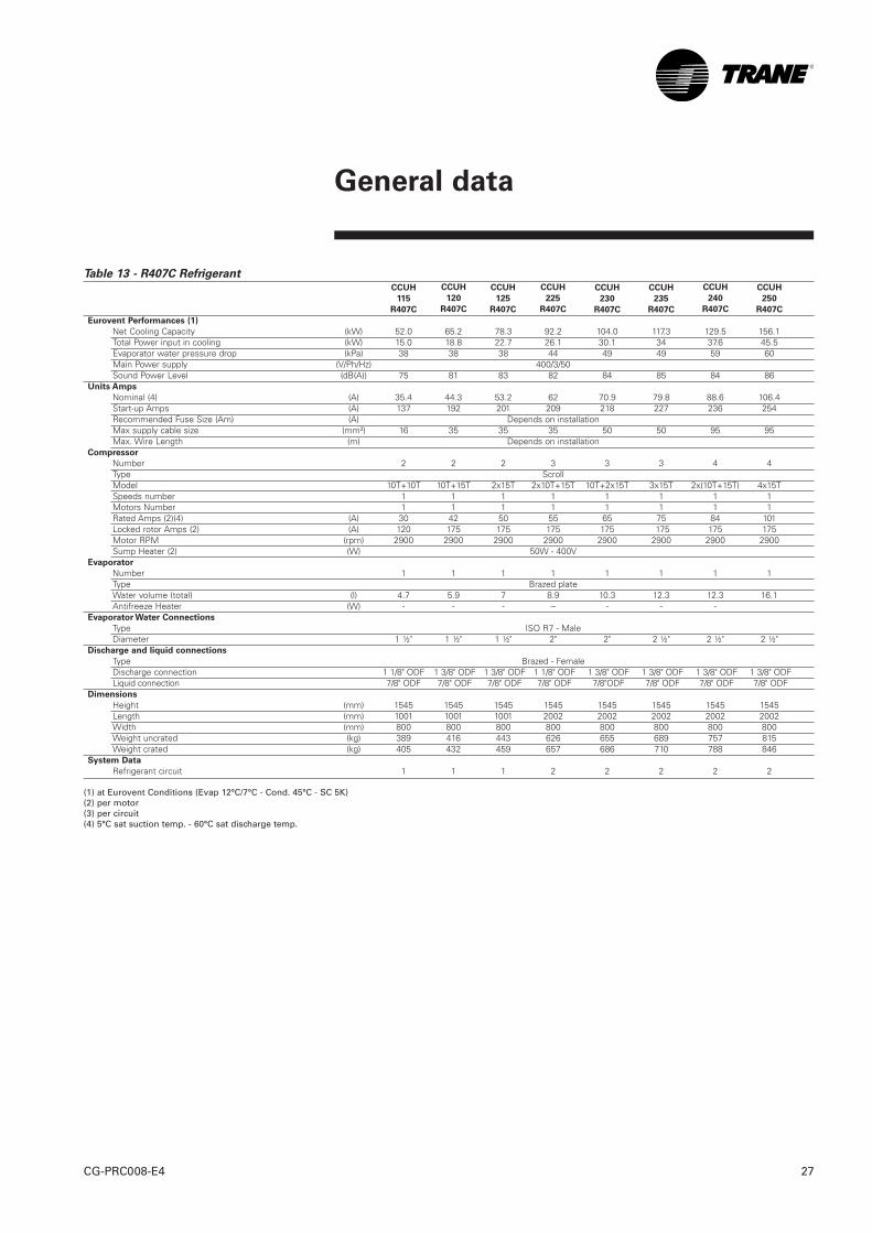
Table 13 - R407C Refrigerant
Eurovent Performances (1)
Net Cooling Capacity (kW) 52.0 65.2 78.3 92.2 104.0 117.3 129.5 156.1Total Power input in cooling (kW) 15.0 18.8 22.7 26.1 30.1 34 37.6 45.5Evaporator water pressure drop (kPa) 38 38 38 44 49 49 59 60Main Power supply (V/Ph/Hz) 400/3/50Sound Power Level (dB(A)) 75 81 83 82 84 85 84 86
Units Amps
Nominal (4) (A) 35.4 44.3 53.2 62 70.9 79.8 88.6 106.4Start-up Amps (A) 137 192 201 209 218 227 236 254Recommended Fuse Size (Am) (A) Depends on installationMax supply cable size (mm²) 16 35 35 35 50 50 95 95Max. Wire Length (m) Depends on installation
Compressor
Number 2 2 2 3 3 3 4 4Type ScrollModel 10T+10T 10T+15T 2x15T 2x10T+15T 10T+2x15T 3x15T 2x(10T+15T) 4x15TSpeeds number 1 1 1 1 1 1 1 1Motors Number 1 1 1 1 1 1 1 1Rated Amps (2)(4) (A) 30 42 50 55 65 75 84 101Locked rotor Amps (2) (A) 120 175 175 175 175 175 175 175Motor RPM (rpm) 2900 2900 2900 2900 2900 2900 2900 2900Sump Heater (2) (W) 50W - 400V
Evaporator
Number 1 1 1 1 1 1 1 1Type Brazed plateWater volume (total) (l) 4.7 5.9 7 8.9 10.3 12.3 12.3 16.1Antifreeze Heater (W) - - - -- - - -
Evaporator Water Connections
Type ISO R7 - MaleDiameter 1 ½" 1 ½" 1 ½" 2" 2" 2 ½" 2 ½" 2 ½"
Discharge and liquid connections
Type Brazed - FemaleDischarge connection 1 1/8" ODF 1 3/8" ODF 1 3/8" ODF 1 1/8" ODF 1 3/8" ODF 1 3/8" ODF 1 3/8" ODF 1 3/8" ODFLiquid connection 7/8" ODF 7/8" ODF 7/8" ODF 7/8" ODF 7/8"ODF 7/8" ODF 7/8" ODF 7/8" ODF
Dimensions
Height (mm) 1545 1545 1545 1545 1545 1545 1545 1545Length (mm) 1001 1001 1001 2002 2002 2002 2002 2002Width (mm) 800 800 800 800 800 800 800 800Weight uncrated (kg) 389 416 443 626 655 689 757 815Weight crated (kg) 405 432 459 657 686 710 788 846
System Data
Refrigerant circuit 1 1 1 2 2 2 2 2
(1) at Eurovent Conditions (Evap 12°C/7°C - Cond. 45°C - SC 5K)(2) per motor(3) per circuit(4) 5°C sat suction temp. - 60°C sat discharge temp.
CCUH
115
R407C
CCUH
120
R407C
CCUH
125
R407C
CCUH
225
R407C
CCUH
230
R407C
CCUH
235
R407C
CCUH
240
R407C
CCUH
250
R407C

Hydraulic data
CG-PRC008-E428
Figure 4 - Evaporator water pressure drop
1 CGWH - CCUH 1152 CGWH - CCUH 1203 CGWH - CCUH 1254 CGWH - CCUH 2255 CGWH - CCUH 2306 CGWH - CCUH 235 / 2407 CGWH - CCUH 250
Figure 5 – Condenser water pressure drop
1 CGWH 1152 CGWH 1203 CGWH 1254 CGWH 2255 CGWH 2306 CGWH 235 / 2407 CGWH 250

Sound performances
29CG-PRC008-E4
Table 14 - Sound spectrum
Notes on sound power levels:Sound power levels determined in accordance with ISO 3746-1996 for the overall sound power level in dBA.The sound levels given by octave band are for information only. - Reference source 1 pW.- Sound power levels are valid under free field conditions only, on a reflecting surface (directivity = 2) on all sides of the unit, for + 35°C ambient maximum.The compressor sound attenuating jackets permit to gain 3dBA.
CGWH & CCUH - Sound Data
Size 63Hz 125Hz 250Hz 500Hz 1000Hz 2000Hz 4000Hz 8000Hz dB(A)
115 81 63 58 74 67 70 59 49 75
120 85 62 64 77 73 72 67 57 79
125 87 62 67 79 76 73 69 59 81
225 92 68 67 77 75 74 69 60 80
230 94 68 70 79 77 75 71 62 82
235 95 67 71 80 78 76 73 64 83
240 95 63 68 77 78 75 69 59 82
250 97 63 70 79 80 77 71 61 84
Units schematics
CG-PRC008-E430
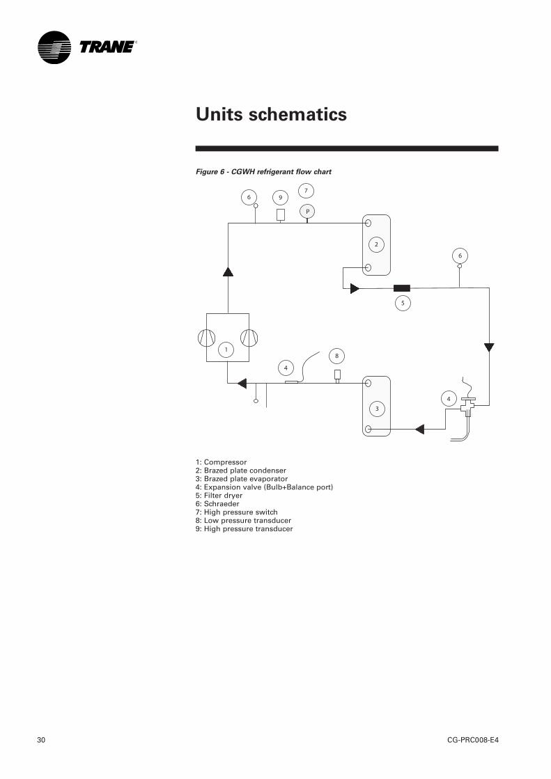
Figure 6 - CGWH refrigerant flow chart
1: Compressor2: Brazed plate condenser3: Brazed plate evaporator4: Expansion valve (Bulb+Balance port)5: Filter dryer6: Schraeder7: High pressure switch8: Low pressure transducer9: High pressure transducer

Units schematics
31CG-PRC008-E4
Figure 7 – CCUH refrigerant flow chart
1: Compressor2: Brazed plate evaporator3: Expansion valve (Bulb+Balance port)4: Stop valve5: Solenoid valve6: Schraeder7: High pressure switch8: Low pressure transducer9: High pressure transducer
69
4
4
6
8
2
1
3
8
6
3
7
P

Literature order number CG-PRC008-E4
Date 0507
Supersedes CG-PRC008-GB _0301, ACDS-PRC002-GB_0101
Stocking location Europe
Trane has a policy of continuous product and product data improvement and reserves the right tochange design and specifications without notice. Only qualified technicians should perform theinstallation and servicing of equipment refferred to in this publication.A business of American Standard Companies
www.trane.com
For more information, contact your local Tranedistrict office or e-mail us at [email protected]
For additional information, contact :
Distributor / Installer stamp
The manufacturer has a policy of continuousproduct improvement, and reserves the right to alterany details of the products at any time withoutnotice.
This publication is a general guide to install, useand properly maintain our products. The informationgiven may be different from the specification for aparticular country or for a specific order. In thisevent, please refer to your nearest office.
American Standard Europe BVBA/SPRL 1789 Chaussée de Wavre, 1160 Brussels, Belgium NE/ON: 0475 956 135 - RPM/RPR BRUXELLES/BRUSSEL