cgeo international limited
TRANSCRIPT

CGEO INTERNATIONAL LIMITED
Instruction Manual 1 / 20
CGEO INTERNATIONAL LIMITED
Model CGEO-IPIA /IPIB /IPID
MEMS In-place Inclinometer
Instruction Manual (REV A)

CGEO INTERNATIONAL LIMITED
Instruction Manual 2 / 20
TABLE of CONTENTS
1. INTRODUCTION ............................................................................................................................................. 1
2. IN-PLACE INCLINOMETER COMPOSITION .......................................................................................... 2
2.1 CGEO-IPIA /IPIB /IPIDMEMS MODEL INCLINOMETER TRANSDUCER ........................................................... 2 2.2 CGEO-IPIA /IPIB /IPIDMEMS IN-PLACE INCLINOMETER COMPOSITION .................................................... 3
3. INSTALLATION .............................................................................................................................................. 6
3.1 PREPARING FOR INSTALLATION ....................................................................................................................... 6 3.2 USE OF CONNECTION PARTS AND INSTALLATION ESSENTIALS ......................................................................... 6 3.3 INSTALLATION STEPS ...................................................................................................................................... 8 3.4 BACKFILL METHODS AND RECOMMENDATIONS ..............................................................................................10
4. TAKING READINGS......................................................................................................................................11
4.1 FUNCTION DEFINITION OF THE CABLE CORES OF TRANSDUCER .......................................................................11 4.2 PRELIMINARY TEST ........................................................................................................................................12 4.3 INSULATION TEST ...........................................................................................................................................14
5. DATA REDUCTION .......................................................................................................................................14
5.1 SETTLEMENT CALCULATION PRINCIPLE ..........................................................................................................14 5.2 CGEO-IPIA /IPIB /IPID SETTLEMENT CALCULATION ...................................................................................15 5.3 TEMPERATURE COMPENSATION ......................................................................................................................16 5.4 ENVIRONMENTAL FACTORS ...........................................................................................................................16
6. TROUBLESHOOTING ...................................................................................................................................16
APPENDIX A - THERMISTOR TEMPERATURE DERIVATION ...................................................................18

CGEO INTERNATIONAL LIMITED
Instruction Manual 1 / 20
1. INTRODUCTION
The Model CGEO-IPIA /IPIB /IPID MEMS Horizontal In-Place Inclinometer system is
designed for long-term monitoring of differential settlements beneath structures such as dams,
landfills, embankments, storage tanks and the like. The basic principle is the utilization of tilt
sensors to make accurate measurement of inclination, over segments, in boreholes drilled into the
structure being studied. The continuous nature of the instrument allows for very precise
measurement of changes in the borehole profile to be measured. The instrument is installed in
standard grooved inclinometer casing.
CGEO-IPIA /IPIB /IPID MEMS Horizontal In-Place Inclinometer system is installed in φ
70mm~80mm standard grooved inclinometer casing. Every inclinometer casing can install 12
pieces of instruments ( the number is un-limited if changing the cable layout manner) and
connecting through wheel assembly and joint casing, see the figure 1.
Figure 1-1 CGEO-IPIA /IPIB /IPID In-Place inclinometer horizontal installation diagram
Data
acquisit
ion
Cap
Concrete
Inclinometer
Soil
β

CGEO INTERNATIONAL LIMITED
Instruction Manual 2 / 20
Figure 1-2 CGEO-IPIA /IPIB /IPID In-Place inclinometer slope installation diagram
In addition , also provide the In-Place Inclinometer installed in the slopes, which is derived from
the Horizontal In-Place Inclinometer(the range is 0°±10°), the inclinometer should lean to a
preset angle β as a initial position (that is, β±10°), basing on the obliquity as a standard to
measure. The obliquity is provided by customers and customized, marked the installation angle
behind the transducer model, like CGEO-IPIA /IPIB /IPID(35°), representing the transducer
installation angle is 35 degree.
2. In-Place Inclinometer composition
2.1 CGEO-IPIA /IPIB /IPID MEMS model inclinometer transducer
The transducer is the core parts of In-Place 4 Inclinometer transducers including Micro-
Electrical-Mechanical-Sensor, signal converter board and conductor packed in a sealed housing.
There are two mounting holes used for the connection to the wheel assembly on a section of
connecting plate on the transducer housing and the threaded hole on the bottom of transducer
used for the installation of the wedge expansion plug so as to connection with the connecting
tube.
+
-
Positive
Negative
Horizontal CGEO-IPI
Figure 2-1 CGEO-IPIA /IPIB /IPID Horizontal In-Place Inclinometer Transducer
+
-
inclinationβ Horizontal
Figure2-2 CGEO-IPIA /IPIB /IPID Slope In-Place Inclinometer transducer

CGEO INTERNATIONAL LIMITED
Instruction Manual 3 / 20
There are marks “+”and“-” on the end of transducer near to the cable, when the
transducer is in a level condition , the output reading should be near to 0. For the slope In-place
inclinometer, output reading should be near to 0 when its initial position in the customized β
slope, see figure 2-2.
The standard 8 core cable is used for the transducer’s power supply, the output of tilt and
temperature signals.
2.2 CGEO-IPIA /IPIB /IPID MEMS In-Place inclinometer composition
1)Inclinometer transducer
The standard CGEO-IPIA /IPIB /IPID Horizontal In-Place transducer has a threaded hole on the
its bottom, mounted a wedged connection parts, which is also possibly not mounted and placed
in fitting parts package.
CGEO IPI
螺纹孔 Threaded hole 连接板 Connection board 楔式接头 Wedge joint
Figure 2-3 CGEO-IPIA /IPIB /IPID inclinometer transducer shape
2)middle wheel assembly
Shown as in the figure, the middle wheel assembly consists of the wheel brackets, stationary
wheel, spring load wheel, the universal joint rotatable in axis direction and wedge-shaped
expansion joint.
Spring load wheel
Stationary wheel
Universial Joint
Wedge joint
Transducer fix
bolt Swivel coupling
Figure 2-4 middle wheel assembly structure
The middle wheel assembly bottom has two mounting holes used for connecting the slope
transducer, the top wedge-shaped expansion joint used for connecting with the tube. The middle
wheel assembly and the slope transducer are used in pair so the number of both is same. The
wheel assembly has a stationary wheel and spring load wheel, the spring load wheel is used for

CGEO INTERNATIONAL LIMITED
Instruction Manual 4 / 20
its locating inside inclinometer casing, the stationary wheel is adown and the spring load wheel is
upwards.
The end of the wheel assembly is installed a universal joint and swivel coupling which
accommodate any spiraling of the casing, and prevents the wheel assemblies from running out of
the casing grooves.
3)Bottom wheel assembly
The bottom wheel assembly is used for installing in the end (hole bottom), is same as the middle
wheel assembly except without universal coupling and is not used in place of middle wheel
assembly .
Figure 2-5 Bottom wheel assembly structure
Every group of Horizontal In-Place Inclinometer only configures one bottom wheel assembly.
4) Orifice fix component
The orifice fix component is installed in the orifice of the inclinometer casing and connected
with the nearest middle wheel assembly, its function is to prevent the whole in-place
inclinometer system to sliding to the hole bottom. The orifice fix component is suit to the
inclinometer casing of diameter 58-86mm.
The orifice fix component consists of the wedge-shaped coupling used for connection, orifice
pendent and suspension link. Every Horizontal In-place inclinometer system is configured one
set of orifice fix component.

CGEO INTERNATIONAL LIMITED
Instruction Manual 5 / 20
Figure 2-6 orifice pendant and fix component
5)Tubing
The tubing is special stainless steel tube of diameter 20mm and the standard length 2m and also
configured shorter tubing basing on the length customers ordered.
Figure 2-7 tubing
In field sometimes need to make some fine adjustment basing on the actual length, so normally
the configured connecting tubing length has some surplus and need to cut some in field.
6)Wedge-shaped coupling
There are kinds of wedge-shaped couplings, one end connecting and two ends of connecting
respectively. The one end of wedge-shaped coupling is normally installed in transducer, wheel
assembly and orifice fix component but the two ends of coupling is used for lengthening the
tubing.
Extended link nut
Figure 2-8 one direction and double directions coupling
The wedge-shaped coupling consists of connecting threaded rod, wedge-shaped expansion tube,
locknut, plain cushion and extended connecting threaded rod. A qualified wedge-shaped
coupling can bear not less than 500kg weight

CGEO INTERNATIONAL LIMITED
Instruction Manual 6 / 20
7) Inclinometer casing (optional)
The inclinometer casing is not included in the components of Horizontal In-Place inclinometer
system but purchased by customers. There are several types of inclinometer casing, glass fiber,
like aluminum alloy, ABS engineering plastics and PVC basing on their materials. Thereamong,
the functions of the glass fiber inclinometer casing is best, its pressure-resistance and corrosion
resistance is good. They have the diameter 60mm, 70mm, 80mm and other specifications, the
CGEO-IPIA /IPIB /IPID model is best suit to install inside φ70mm and 80mm inclinometer
casing which has the vertical pair of grooves. The installation of the Horizontal In-Place
Inclinometer requires only one of pairs of grooves plane locates in vertical direction.
3. Installation
3.1 Preparing for installation
Installation tools: 2 pieces of small pipe clamp, 2 pieces of fixed wrench of mouth breadth
16mm, Hacksaw, rasp and the tools and materials required for the connection of inclinometer
casing, these tools are self-provided by customers.
3.2 Use of connection parts and installation essentials
The wedge-shaped expansion joint is to use of wedge-shaped expansion tube to connect with the
tube and consists of threaded bolt, a pair of wedge-shaped expansion tube, plain cushion and two
nuts. Under any circumstance must the expansion end connect with the connecting tube in the
installation of wedge-shaped expansion joint and then connect the threaded end with other
related parts after fixed. Shown as the figure below, first adjust wedge-shaped expansion joint
and insert in the connecting tube, note to place the plain cushion correctly.
Insert the nut close to the connecting tube end and screw down with hand, stick the connecting
tube with a pipe clamp and screw down the nut close to the connecting tube end with a spanner
(recommend to use a thin bayonet fixed spanner).The connection strength of a qualified
connection between the wedge-shaped expansion joint and connecting tube can bear not less than
500kg pull.

CGEO INTERNATIONAL LIMITED
Instruction Manual 7 / 20
tubing
tubing
Screw down
Figure 3-1 connection between connector and connecting tubing
After completion of the expansion end connection, screw a nut of thread end into the
connecting end, screw the thread part into a transducer or similar parts(like middle wheel
assembly, middle joint, orifice fix parts etc), screw down the nut of thread end to the connected
end direction with a spanner to lock out the thread rod. Note to not touch the nut in the
connecting end during screwing the nut, that is, avoid loosing the nut of connecting end.
Tube Transducer connecting hole or wheel assembly
Tube Transducer connecting hole or wheel assembly
Tube
BSIL-C12
Figure 3-2 connection of the connecting tubing and transducer
As to the double end joint connection, first connect expansion end and then thread end, see the
figure below

CGEO INTERNATIONAL LIMITED
Instruction Manual 8 / 20
tube tube
tube
tube
tube
tube
Figure 3-3 connection extension of connecting tubing
Figure 3-4 connection between the connecting rod and wheel assembly
3.3 Installation steps
The installation of the Horizontal In-Place Inclinometer and inclinometer casing are
simultaneously carried out, the installation zone is preserved in installation profile and should be
compacted to dense and maintained smooth. Installing in the rockfill zone, transition material
bedding layers and the coarse sand bedding should be set.
The installation of inclinometer casing starts from the deepest end, the tubing cap should be put
on the end. Some quantity of compression space should be reserved in the connection of
inclinometer casing, the connection of the inclinometer casing depends on its materials (riveting
or bonding).The first end is generally installed 8 m length and then assemble the inclinometer.
The in-place inclinometer should start from the bottom wheel, connect with corresponding
connector and tube, while connecting first transducer, determine the central distance between
two neighboring wheels basing on the design size, cut the surplus tube with a hacksaw, rasp the
orifice burrs and connect the transducer and wheel assembly.
When completing the connection of the two neighboring wheel assemblies, you should measure
the central distance between two wheels and record the length L, shown as in the figure below,
the distance L will be a important parameter to this position inclinometer calculation.
CGEO INTERNATIONAL LIMITED
Instruction Manual 9 / 20
Space L
Figure 4-1 size determination of the installation space
Note the installation direction when installing the transducer, keep the spring load wheel and the
plus mark “+” on the transducer in same direction, that is, keep the positive direction of the
transducer upwards and fix with a bolt lastly.
After completing the first section of installation, push the wheel assembly and transducer into
the inclinometer casing and keep the stationary wheel on the wheel assembly adown, that is,
maintain same direction.
The rest installation is first to install in-place inclinometer components and then set into the
inclinometer casing.
All instruments cable should be marked well, including transducer series number, cable length,
and same time record the instrument position, installation depth, space L and other relative data.
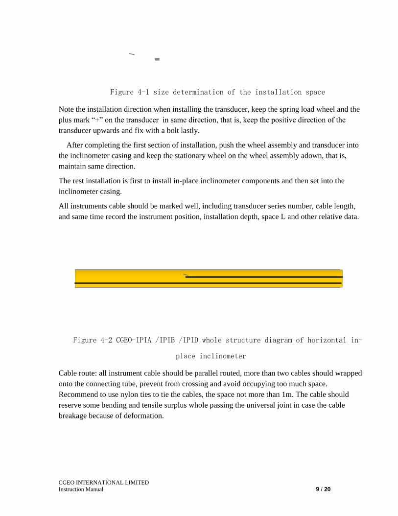
Cable
Figure 4-2 CGEO-IPIA /IPIB /IPID whole structure diagram of horizontal in-
place inclinometer
Cable route: all instrument cable should be parallel routed, more than two cables should wrapped
onto the connecting tube, prevent from crossing and avoid occupying too much space.
Recommend to use nylon ties to tie the cables, the space not more than 1m. The cable should
reserve some bending and tensile surplus whole passing the universal joint in case the cable
breakage because of deformation.

CGEO INTERNATIONAL LIMITED
Instruction Manual 10 / 20
cable
tubing
sensor
Wheel
assembly
ties
Figure 4-3 cable route profile of in-place inclinometer in inclinometer casing
Regarding the In-place inclinometer system more than 9 transducers, the inclinometer casing can
not accommodate too many cables, and can lead part of transducer cables out of the inclinometer
casing and protected with steel pipe to lead to the orifice of the inclinometer casing, the diameter
of protection steel pipe depends on the number of the cables, normally 1.5″~2″.
Cable
Cable fairlead
Cable protection pipe Scalable connector
Figure 4-4 Multi-transducer cable laying and protection
Note to wrap the cable with soft materials in the orifice of the inclinometer casing in case the
orifice burrs damaging the cable. In addition, the connection of the cable protection pipe can not
use the connector with buckles and recommend to use a steel pipe (length 30~50cm) little bigger
than the protection pipe, also please note to maintain about 10cm space between the protection
pipes for compression.
All the instruments are lead to the observation station or observation room and connected with
the corresponding data acquisition equipment.
The installation of the In-place Inclinometer mounted in a slope is similar to that of Horizontal
In-Place Inclinometer, that is, maintain the mark on the transducer upwards and the stationary
wheel downwards to the bottom of the inclinometer casing.
3.4 Backfill methods and recommendations
The backfill instruction is only the case of rockfill, the installation of other fill materials can
refer to this method. The backfill materials should be same as the site materials, for example, the

CGEO INTERNATIONAL LIMITED
Instruction Manual 11 / 20
burry in earth dam should use the same clay backfill and the burry in rockfill should use coarse
sand, transitional materials backfill one layer by one layer, the thickness of the coarse and
transitional materials cover are not less than 50 and 30cm. First compact with hand and only the
thickness of the cover is over 1m and then roll with a roller.
Figure4-5 laying backfill diagram of horizontal in-place inclinometer
installed in the inclinometer casing
4. Taking readings
4.1 Function definition of the cable cores of transducer
CGEO-IPIA /IPIB /IPID In-Place inclinometer uses an 8 core cable, the 8 core cable consists of
4 twisted pair and another shield wire, the 8 core wire definition as the following:
core color function definition
double axes uni-axis
Red 12V power
(+)
12V power
(+)
Black, red black
twisted pair
12V power
(-)
12V power
(-)
White A axis signal
(+)
A axis signal
(+)
Black, white black
twisted pair A axis signal A axis signal
Green B axis signal
(+)
empty
Black, green black
twisted pair B axis empty
Blue thermistor thermistor
Black, blue black
twisted pair
thermistor thermister
naked wire shield shield
sand
Transition
Rockfill
Cushion
material
Transition
material
25cm
50
m
25cm

CGEO INTERNATIONAL LIMITED
Instruction Manual 12 / 20
Thanks to the voltage signal of transducer output, the transducers can connect with most data
acquisition equipments. Use CGEO-PR-MEMS readout to take readings on site manually, also
can use most commercially available dataloggers to automatically or remotely acquire data.
Regarding the use of CGEO-PR-MEMS readout please refers to its manual instruction or consult
to CGEO Company.
4.2 Preliminary test
Prior to installation, the sensors need to be checked for proper operation. Each tilt sensor is
supplied with a calibration sheet, which shows the relationship between output voltage and
inclination. The tilt sensor electrical leads are connected to a datalogger or CGEO-PR-MEMS
readout box and the current reading compared to the calibration readings. Carefully hold the
sensor in an approximately horizontal position and observe the reading. The sensor must be held
in a steady position. The readings should be close to the factory horizontal reading. The
temperature indicated by the thermistor, and readout on the green and white wires using an
ohmmeter, should be close to ambient.
Inclination measured vales average
accuracy
θ sinθ 1 2 3 linear polynormal
-12.0 -0.2079 -1.6712 -1.6712 -1.6712 -1.6712 -0.03% 0.01%
-9.0 -0.1564 -1.2580 -1.2579 -1.2580 -1.2579 -0.01% -0.01%
-6.0 -0.1045 -0.8415 -0.8415 -0.8413 -0.8414 0.00% -0.01%
-3.0 -0.0523 -0.4227 -0.4226 -0.4225 -0.4226 0.02% 0.00%
0.0 0.0000 -0.0025 -0.0022 -0.0021 -0.0022 0.02% 0.00%
3.0 0.0523 0.4180 0.4182 0.4182 0.4181 0.03% 0.01%
6.0 0.1045 0.8378 0.8380 0.8379 0.8379 0.02% 0.01%
9.0 0.1564 1.2556 1.2559 1.2558 1.2557 0.00% 0.00%
12.0 0.2079 1.6705 1.6708 1.6709 1.6707 -0.05% -0.01%
/ / / / / / /
formula linear D(mm) = G×L (R1 -R0)
polynomial D(mm) =L (AR12 + BR1 + C )
Linear coefficient
G = 0.1244497644 sinθ/Volt
Polynomial
coefficient A = -0.000093110144 B =0.124449683838
C = 0.0002870555690215
R1---current readings R0-initial readings
L-distance between two inclinometers (mm)
Note: readout display is half of output voltage of transducer
----Blank below----
Figure 4-6 sample calibration sheet of in-place inclinometer

CGEO INTERNATIONAL LIMITED
Instruction Manual 13 / 20
Detecting steps: connect the instrument with power and CGEO-PR-MEMS or other data
acquisition equipment according the core wire definition; please note the power supply is 12V
stabilized voltage supply. The reading ranges of A and B axis is +1.9999~1.9999, changing the
inclination of inclinometer to see if the reading is normal, the inclinometer should have a stable
readings. There are normally marks “+”and “-” on the cable end; the inclinometer
readings will increase (0~1.9999)when the inclinometer incline upwards to “+” otherwise
the readings will decrease (0~-1.9999); The readings of the inclinometer will be near to zero
when it is in a level position.
It must be explained that, using CGEO-PR-MEMS to read , the display values are the 1/2 output
voltages of inclinometer transducer.
Figure 4-7 diagram of the transducer inclination direction and reading
variation tendency
The temperature sensor is independent, use CGEO-PR-VW to read and display the degrees
directly; the value should be close to the ambient temperature. Or use the CGEO-PR-MEMS
ohm grade or other digital multimeter to measure the thermistor resistance. The resistance of the
temperature sensor at 25℃ is about 3000 ohms. Resistance to Temperature Equation:
TA B LnR C LnR
1
27323( ) ( ).
Equation B-1 Convert Thermistor Resistance to Temperature
Where; T Temperature in C.
LnR Natural Log of Thermistor Resistance
A 1.4051 10-3 (coefficients calculated over the 50 to +150 C. span)
B 2.369 10-4
C 1.019 10-7

CGEO INTERNATIONAL LIMITED
Instruction Manual 14 / 20
See the appendix B.
4.3 Insulation test
Different from the regular instruments, this transducer contains some Precision Electronic
Components and works in low voltage range, so you can not use a traditional insulation
resistance meter to test the insulation resistance of the instrument, otherwise will damage the
instrument. When measuring , you must twist all cable core conductor together and only allow to
use 50V megameter or digital multimeter to test the insulation resistance between core wires and
shield wire or outside shell, its insulation resistance should be bigger than 2 megaohms. The
factory shall not repair or exchange if mis-using 50v over megameter and damage the
instrument.
5. Data reduction
5.1 Settlement calculation principle
Shown as in the figure, supposed the length of a inclinometer is L, when inclining (rotating)
angle θ related to o point, and then A point displaces to A’, then D=L×sinθ.
D
L
θ
O A
A′
Figure 5-1 vertical displacement transition principle
If multi-instruments in series, the accumulation displacement of these instruments will get the
vertical deformation curve of the whole profile.
D4 D3 D2 D1
L Lsinθ
θ
∑L
i×si
nθi
Initial position

CGEO INTERNATIONAL LIMITED
Instruction Manual 15 / 20
Figure 5-2 transition diagram of incline and settlement
Supposed installing 5 points of horizontal in-place inclinometers (see figure 22), L end as a
benchmark, the total vertical displacement generated in L end is:
D5 =D1+D2+D3+D4+D5
5.2 CGEO-IPIA /IPIB /IPID settlement calculation
The output of the inclinometer is a voltage signal and the calculation methods are a little
different when using different display instrumentation and data acquisition devices
1)If using CGEO-PR-MEMS readout box, you directly use the formula supplied in the
calibration sheet.
D(mm) = G×L (R1 -R0)
Where: D-the vertical offset related to the inclinometer length L(mm);
G-instrument coefficient, given in the calibration sheet (sin/V, using CGEO-PR-MEMS to
measure);
L-single transducer inclinometer length or the central distance between the neighboring
wheels (mm);
R1-current readings (the readings measured by CGEO-PR-MEMS, unit 1/2 V);
R2-initial readings (using CGEO-PR-MEMS readout)
2)when using other data acquisition equipment, its display result is the actual output voltage of
transducer, taking this voltage value half, that is, calculate as the following formula:
D(mm) = 0.5×G×L (R1 -R0)
Where:D-the vertical offset related to the inclinometer length L
G-instrument coefficient, given in the calibration sheet(sin/V);
L-the single transducer inclinometer length or the central distance between the two
neighboring wheels (mm);
R1-current readings (unit, V)
R2-Initial readings (unit, V)
The reading range is ±12° when calibrating CGEO-IPIA /IPIB /IPID in the factory, its
measurement range can reach±15° when using, the corresponding transducer output is ±12°@
±4V.

CGEO INTERNATIONAL LIMITED
Instruction Manual 16 / 20
5.3 Temperature compensation
Although the temperature dependence of the MEMS tilt meter is practically zero, and does not
require compensation, it sometimes happens that temperature effects can cause real changes of
tilt, therefore each MEMS tilt sensor is equipped with a thermistor for reading temperature. This
enables temperature-induced changes in tilt to be distinguished from tilts due to other sources.
The thermistor gives a varying resistance output as the temperature changes. The temperature
property of CGEO-IPIA /IPIB /IPID is that the signal output will decrease 0.0005Vevery 1℃
rising (the variation in CGEO-PR-MEMS is 0.00025V), then the temperature corrected readings
are:
RT =R+0.0005 (T1-T0)
When using CGEO-PR-MEMS readout, the corrected displacement variation is:
D(mm) = G×L (R1-R0+0.00025 (T1-T0))
When using datalogger to read, the corrected displacement variation is:
D(mm) =0.5×G×L (R1-R0+0.0005 (T1-T0))
5.4 Environmental Factors
Since the purpose of the CGEO-IPIA /IPIB /IPID MEMS installation is to monitor site
conditions, factors that may affect these conditions should be observed and recorded. Seemingly
minor effects may have a real influence on the behavior of the structure being monitored and
may give an early indication of potential problems. Some of these factors include, but are not
limited to: blasting, rainfall, tidal or reservoir levels, excavation and fill levels and sequences,
traffic, temperature and barometric changes, changes in personnel, nearby construction activities,
seasonal changes, etc.
6. TROUBLESHOOTING
Maintenance and troubleshooting of the vibrating wire tilt sensors used in the Model CGEO-
IPIA /IPIB /IPID MEMS Horizontal Inclinometer are confined to periodic checks of cable
connections. The sensors are sealed and there are no user-serviceable parts.
Consult the following list of problems and possible solutions should difficulties arise. Consult
the factory for additional troubleshooting help.
Symptom: Tilt Sensor Readings are Unstable

CGEO INTERNATIONAL LIMITED
Instruction Manual 17 / 20
Is there a source of electrical noise nearby? Most probable sources of electrical noise are
motors, generators and antennas. Make sure the shield drain wire is connected to ground
whether using a portable readout or datalogger.
Does the readout work with another tilt sensor? If not, the readout may have a low battery or
be malfunctioning.
Symptom: Tilt Sensor Fails to Read
Is the cable cut or crushed? This can be checked with an ohmmeter. The nominal resistance
of the thermistor is 3000 ohms at 25 degrees C. If the approximate temperature is known, the
resistance of the thermistor leads can be estimated and used as a cable check. Remember to
add cable resistance when checking (22 AWG stranded copper leads are approximately
14.7/1000' or 48.5/km, multiply by 2 for both directions). If the resistance reads infinite,
or very high (megohms), a cut wire must be suspected. If the resistance reads very low
(20) a short in the cable is likely.
Does the readout or datalogger work with another tilt sensor? If not, the readout or
datalogger may be malfunctioning.
Symptom: Thermistor resistance is too high.
Is there an open circuit? Check all connections, terminals and plugs.
Symptom: Thermistor resistance is too low.
Is there a short? Check all connections, terminals and plugs.
] Water may have penetrated the interior of the tilt sensor. There is no remedial action.

CGEO INTERNATIONAL LIMITED
Instruction Manual 18 / 20
APPENDIX A - THERMISTOR TEMPERATURE DERIVATION
Thermistor Type: YSI 44005, Dale #1C3001-B3, Alpha #13A3001-B3
Resistance to Temperature Equation:
TA B LnR C LnR
1
27323( ) ( ).
Equation B-1 Convert Thermistor Resistance to Temperature
Where; T Temperature in C.
LnR Natural Log of Thermistor Resistance
A 1.4051 10-3 (coefficients calculated over the 50 to +150 C. span)
B 2.369 10-4
C 1.019 10-7
Ohms Temp Ohms Temp Ohms Temp Ohms Temp Ohms Temp
201.1K -50 16.60K -10 2417 30 525.4 70 153.2 110
187.3K -49 15.72K -9 2317 31 507.8 71 149.0 111
174.5K -48 14.90K -8 2221 32 490.9 72 145.0 112 162.7K -47 14.12K -7 2130 33 474.7 73 141.1 113
151.7K -46 13.39K -6 2042 34 459.0 74 137.2 114
141.6K -45 12.70K -5 1959 35 444.0 75 133.6 115 132.2K -44 12.05K -4 1880 36 429.5 76 130.0 116
123.5K -43 11.44K -3 1805 37 415.6 77 126.5 117
115.4K -42 10.86K -2 1733 38 402.2 78 123.2 118 107.9K -41 10.31K -1 1664 39 389.3 79 119.9 119
101.0K -40 9796 0 1598 40 376.9 80 116.8 120
94.48K -39 9310 1 1535 41 364.9 81 113.8 121
88.46K -38 8851 2 1475 42 353.4 82 110.8 122
82.87K -37 8417 3 1418 43 342.2 83 107.9 123
77.66K -36 8006 4 1363 44 331.5 84 105.2 124 72.81K -35 7618 5 1310 45 321.2 85 102.5 125
68.30K -34 7252 6 1260 46 311.3 86 99.9 126
64.09K -33 6905 7 1212 47 301.7 87 97.3 127 60.17K -32 6576 8 1167 48 292.4 88 94.9 128
56.51K -31 6265 9 1123 49 283.5 89 92.5 129
53.10K -30 5971 10 1081 50 274.9 90 90.2 130 49.91K -29 5692 11 1040 51 266.6 91 87.9 131
46.94K -28 5427 12 1002 52 258.6 92 85.7 132
44.16K -27 5177 13 965.0 53 250.9 93 83.6 133 41.56K -26 4939 14 929.6 54 243.4 94 81.6 134
39.13K -25 4714 15 895.8 55 236.2 95 79.6 135
36.86K -24 4500 16 863.3 56 229.3 96 77.6 136 34.73K -23 4297 17 832.2 57 222.6 97 75.8 137
32.74K -22 4105 18 802.3 58 216.1 98 73.9 138
30.87K -21 3922 19 773.7 59 209.8 99 72.2 139 29.13K -20 3748 20 746.3 60 203.8 100 70.4 140
27.49K -19 3583 21 719.9 61 197.9 101 68.8 141
25.95K -18 3426 22 694.7 62 192.2 102 67.1 142 24.51K -17 3277 23 670.4 63 186.8 103 65.5 143
23.16K -16 3135 24 647.1 64 181.5 104 64.0 144
21.89K -15 3000 25 624.7 65 176.4 105 62.5 145 20.70K -14 2872 26 603.3 66 171.4 106 61.1 146
19.58K -13 2750 27 582.6 67 166.7 107 59.6 147
18.52K -12 2633 28 562.8 68 162.0 108 58.3 148 17.53K -11 2523 29 543.7 69 157.6 109 56.8 149
55.6 150
Table B-1 Thermistor Resistance versus Temperature