ch-3 fluid statics -...
TRANSCRIPT

Chapter 3: Fluid Statics
ByBy
Dr Ali Jawarneh
1

OutlineWe will discuss:• The definition of pressure.• Pascal’s principle.Pascal s principle.• The concepts of absolute, gage and
vacuum pressuresvacuum pressures.• Pressure variation with elevation for
uniform density fluidsuniform density fluids.
2

Outline• We will become familiar with different
pressure measurement techniques and devices:– Simple and differential manometers– Bourdon-tube gages– Pressure Transducers
3

Outline
• become familiar with hydrostatic forces on• become familiar with hydrostatic forces on plane surfaces.
• Calculate the magnitude of the resultantCalculate the magnitude of the resultant hydrostatic force.
• Locate the line of action of the resultant hydrostatic force.
• Analyse hydrostatic forces on curved fsurfaces.
• Discuss the principle of buoyancy.
4
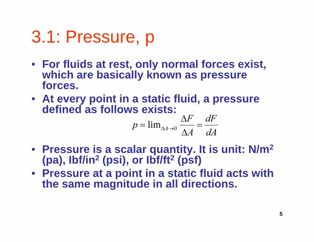
3.1: Pressure, p, p• For fluids at rest, only normal forces exist,
which are basically known as pressurewhich are basically known as pressure forces.
• At every point in a static fluid, a pressure d fi d f ll i tdefined as follows exists:
dAdF
AFp A =ΔΔ
= →Δ 0lim
• Pressure is a scalar quantity. It is unit: N/m2
(pa), Ibf/in2 (psi), or Ibf/ft2 (psf)• Pressure at a point in a static fluid acts with
the same magnitude in all directions.
5
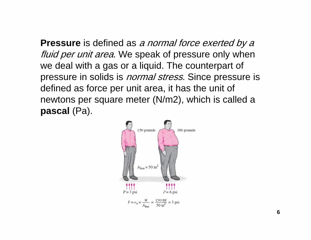
Pressure is defined as a normal force exerted by aPressure is defined as a normal force exerted by a fluid per unit area. We speak of pressure only when we deal with a gas or a liquid. The counterpart of
i lid i l t Si ipressure in solids is normal stress. Since pressure is defined as force per unit area, it has the unit of newtons per square meter (N/m2), which is called a pascal (Pa).
6

Pressure
Considering an element of fluid in equilibrium:
7
Pressure
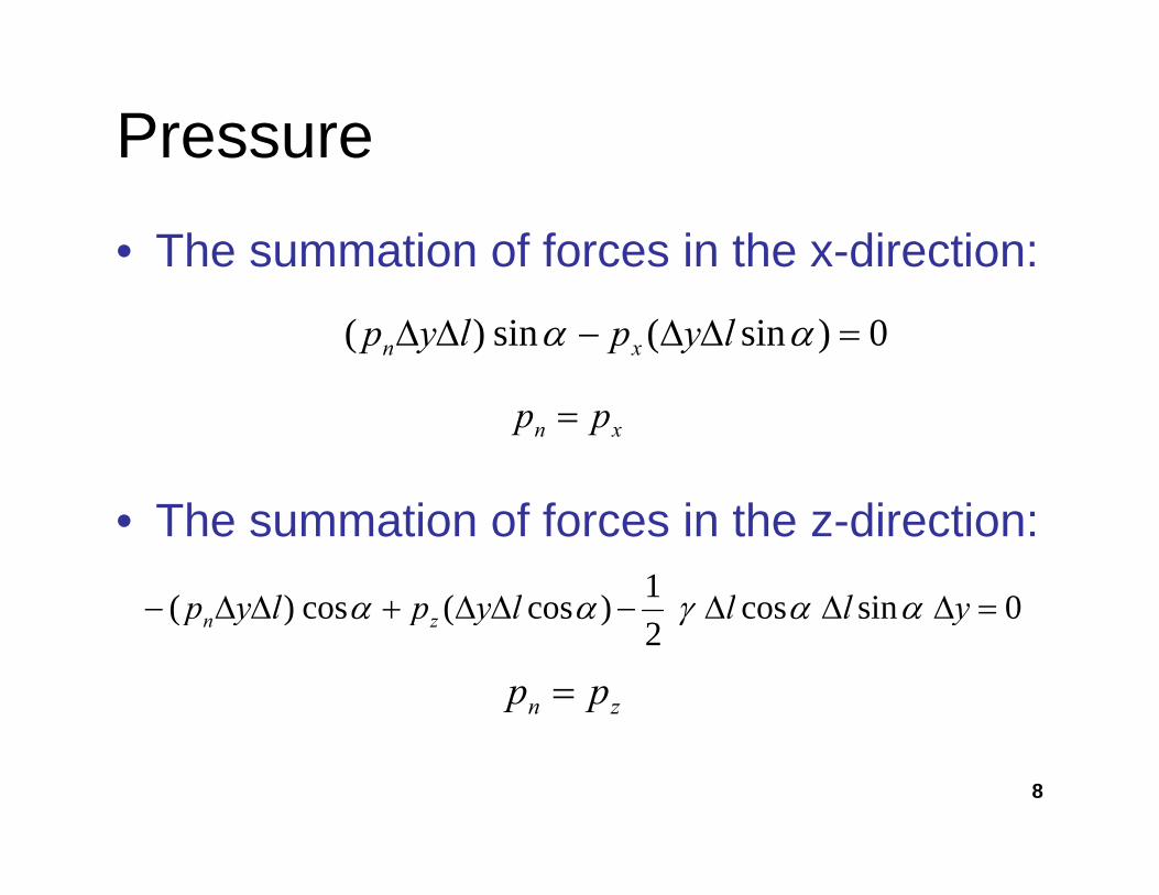
• The summation of forces in the x-direction:
0)sin(sin)( =ΔΔ−ΔΔ αα lyplyp xn
Th ti f f i th di ti
xn pp =
• The summation of forces in the z-direction:
0sincos1)cos(cos)( =ΔΔΔ−ΔΔ+ΔΔ− ylllyplyp ααγαα 0sincos2
)cos(cos)( ΔΔΔΔΔ+ΔΔ ylllyplyp zn ααγαα
zn pp =
8

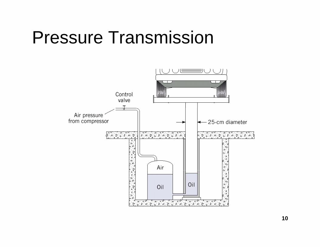
Pressure Transmission Pascal’s law states • Pascal’s principle states that a
pressure change produced at one point in the system will be transmitted
that increase in pressure onthe surface of a confined fluid isp y
throughout the entire system.• A consequence of the pressure in a
fluid remaining constant in the
confined fluid is transmittedundiminished throughout the g
horizontal direction is that the pressure applied to a confined fluid increases the pressure throughout by
confining vessel orsystem
the pressure atp g ythe same amount. This is called Pascal’s law, after Blaise Pascal(1623–1662).
a point in a fluid at rest, or in motion, is independent of direction as long as there are no( )
• This principle is utilised in the design and development of hydraulic controls used in a wide range of applications.
there are noshearing stresses present. This important result is known as Pascal’s law named in h f
9
g pphonor ofBlaise Pascal
Pressure Transmission
10

11

Absolute, Gage, and Vacuum Pressure
P• Pabs=pgage+ patm
• Pressure values measured with reference to the atmospheric pressure are referred to as gage pressures.
• Most pressure measurement devices measure gage pressure, such as the g g p ,Bourdon-tube gage.
12
Absolute and Gage Pressureg
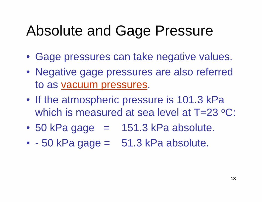
• Gage pressures can take negative values.• Negative gage pressures are also referred
to as vacuum pressures.p• If the atmospheric pressure is 101.3 kPa
which is measured at sea level at T=23 oC:which is measured at sea level at T=23 C:• 50 kPa gage = 151.3 kPa absolute.
50 kP 51 3 kP b l t• - 50 kPa gage = 51.3 kPa absolute.
13

3.2: Pressure Variation with ElevationElevation • The general equation
for pressure variation in the fluid element shown:shown:
dzdp γ=dldl
γ−=
d The pressure changesγ−=
dzdp The pressure changes
inversely with elevation. If one travels upward in the fluid the pressure
14
fluid, the pressure decreases

Pressure Variation with Elevation
• Pressure variation occurs only along a vertical path through the fluid.
• No pressure variation occurs along a p ghorizontal path through the fluid.
• Pressure changes inversely with elevation;Pressure changes inversely with elevation; i.e.: going down increases the pressure and going up decreases the pressureand going up decreases the pressure.
15
Pressure Variation with Elevation
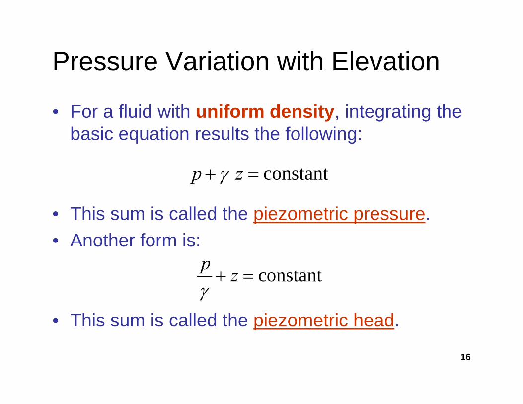
• For a fluid with uniform density, integrating the basic equation results the following:
constant=+ zp γ
• This sum is called the piezometric pressure.
constant=+ zp γ
• Another form is:
constant=+ zp
• This sum is called the piezometric head.
constant=+ zγ
16
p

Pressure Variation with Elevation
• Therefore, the pressure and elevation at one point can be related to the pressure and elevation at another point according to the following:
++ 2211 zpzp γγ +=+
17

- Pressure Variation for Compressible Fluids
• For Ideal gas: p=ρRT or ρ=p/RT• Multiply by g: ρg=pg/RT thenMultiply by g: ρg pg/RT, then
γ=pg/RT• γ =f (p T)• γ =fn (p, T)• dp/dz = -γ = fn (p, T)
18
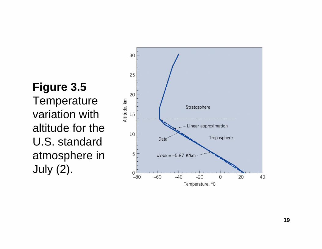
Figure 3.5Temperature variation with altitude for the U S standardU.S. standard atmosphere in July (2)July (2).
19

Example: Find the pressure at the tank bottom.S l ti 9790 N 3 (T bl A 5)Solution: γ =9790 N.m3 (Table A.5)
22
11 zpzp
+=+ 21 zγ
zγ
)(k)(p 5819200 2 )gauge(kpa.p)(γp 5819200 2
2 =→−+=+
Another practical and fast way:pγhp 21 =+
or
kpa.pp))(( 5819297900 22 =→=+
1212 pγhppγhp +=→=−
20
1212 pγhppγhp +→
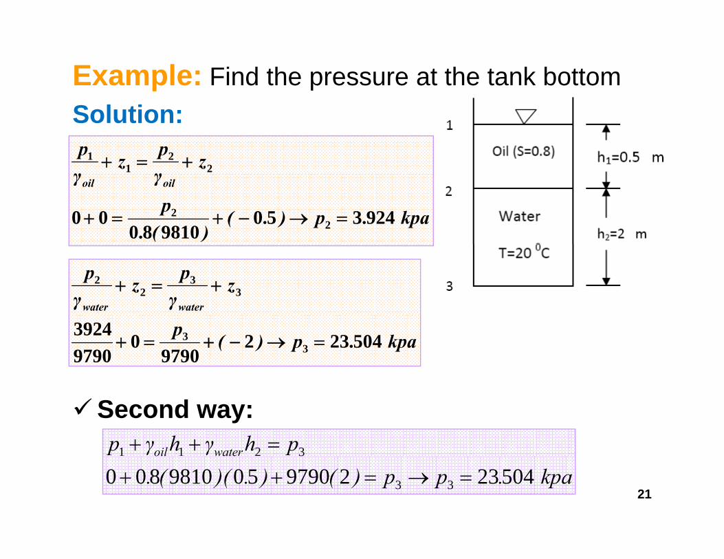
Example: Find the pressure at the tank bottomSolution:
zγpz
γp
22
11 +=+
kpa.p).()(.
pγγ oiloil
924350981080
00 22 =→−+=+
zγpz
γp
waterwater3
32
2 +=+
kpa.p)(p 5042329790
097903924
33 =→−+=+
Second way:phγhγp wateroil 3211 =++
21kpa.pp)().)((.
wateoil
5042329790509810800 33
3
=→=++

Example: Find the pipe pressure if h1=1.2 m, h 1 m and h 3 mh2=1 m, and h3=3 m
SSolution:
phγhγhγp =+−+ 21231 phγhγhγp waterHgoil =++
002198101981061339810901 ....p =×+××−××+
kpapp 15795== kpa.pp pipe 157951 ==
22

Example: Given F1= 200 N, Find the F2. Neglect the eights of the pistonsthe weights of the pistons
Solution:
21 pγhp =−
kpa..A
Fp 23159040
20021
11 =
×== π .040
4
kpa.).(p 558142298108501592302 =××−= kpa.).(p 558142298108501592302 ××
kNAPF 119110142558 2 =××==π
23
kN..APF 1191104
142558222 =××==

M t3.3: Pressure MeasurementsManometry• Pressure is one of the most important
variables in fluid mechanics.• Numerous instruments and devices have
b d l d f it tbeen developed for its measurement.• One of the simplest and most common
t t h i i b dmeasurement techniques is based on hydrostatics or manometry.
• The principle is basically to utilise the• The principle is basically to utilise the change in pressure with elevation to determine the value of the pressure.
24
determine the value of the pressure.

a: Piezometer• A simple manometer,
or a piezometer can be attached to a pipe and the height of theand the height of the liquid’s column is an indicator of theindicator of the pressure in the pipe:
hhp γ=
25
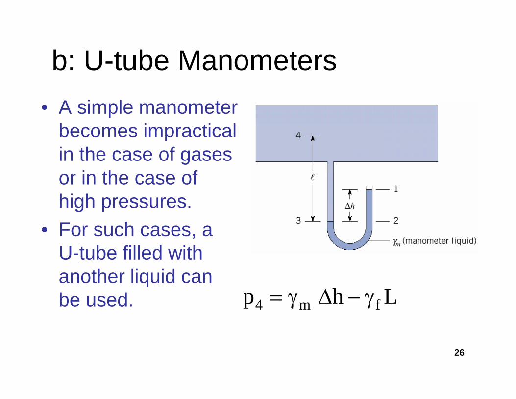
b: U-tube Manometers• A simple manometer
b i ti lbecomes impractical in the case of gases or in the case ofor in the case of high pressures.F h• For such cases, a U-tube filled with another liquid cananother liquid can be used. 4 m fp h L= γ Δ − γ
26

c: Differential Manometers• A differential
manometer can also be used to measure the pressurethe pressure difference between two points in a pipe,two points in a pipe, according to:
hp Δ−=Δ )( γγ hp fm Δ=Δ )( γγ
27
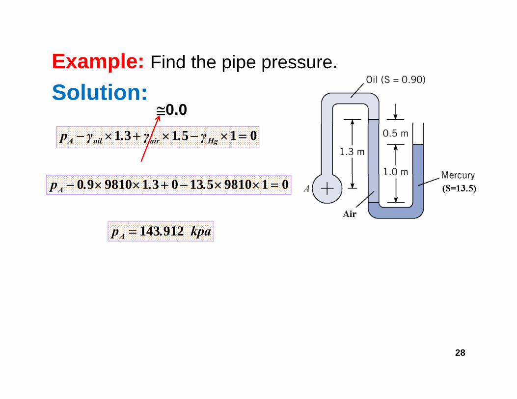
Example: Find the pipe pressure.
Solution:≅0.0
015131 =×−×+×− HgairoilA γ.γ.γp
019810513031981090 =××−+××− ...pA
kpa.pA 912143=
28

• Example: Find the pipe pressure• Solution:
01020501010 33 =××−××+ L.pB
m.L.L.sin 20
5010
53
=→+
==θ
kPapB 1−=
29

- Bourdon-Tube Gageg• The Bourdon-tube
gage is a very common device that utilises the deflectionutilises the deflection in a spring tube to measure themeasure the pressure.
• Bourdon gages need g gto be periodically calibrated.
30

- Pressure Transducers• Similarly, pressure transducers utilise the
deflection of a diaphragm to produce an electrical signal that can be related to the pressure.P t d id l d ith• Pressure transducers are widely used with applications requiring extensive data acquisition and processingand processing.
31
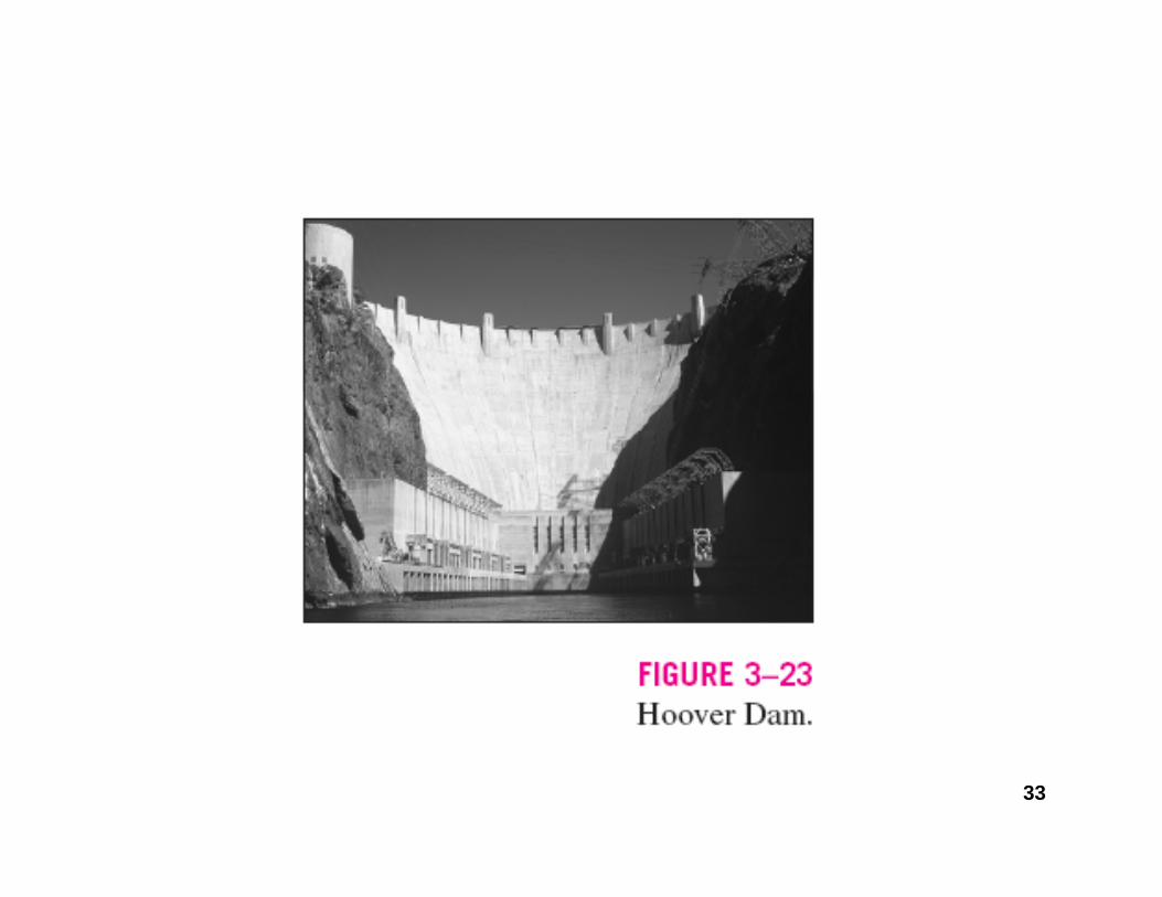
3.4:Hydrostatic Forces on Plane SurfacesSurfaces• For a horizontal surface in a fluid, the
pressure is uniformly distributed and the resulting force is simply equal to the product of the pressure and the area.
• For a vertical or an inclined surface the pressure is not uniformly distributed p yand thus some derivation is required to determine the resulting force.
32
g
33

34
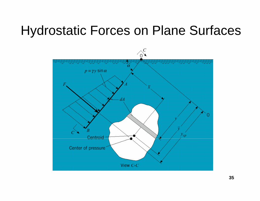
Hydrostatic Forces on Plane Surfacesy
35

Hydrostatic Forces on Plane SurfacesSurfaces• The pressure on the differential area is
equal to:αγ sinyp =
• Consequently, the differential force on the differential area is equal to:differential area is equal to:
A d th t t l f th i l tdAydF αγ sin=
• And the total force on the area is equal to:dAyF αγ sin∫=
36A∫

Hydrostatic Forces on Plane SurfacesSurfaces• Rewriting,
• Integrating:
dAyFA∫= αγ sin
Integrating:
I h t th it d f th lt tApAyF == αγ sin
• In short, the magnitude of the resultant hydrostatic force on a plane surface is the
d t f th t th t id fproduct of the pressure at the centroid of the surface and the area of that surface.
37

Location of Resultant Hydro. Forcey
• The location of the line of action of the resultant hydrostatic force lies at a point called the center of pressure.
• Writing the moment equation:
∫∫ dAdFF
O
∫∫ == dApydFyFycp
• Or:∫= dAyFycp αγ sin2
38

Location of Resultant Hydro. Forcey
• Re-writing:
∫= dAyFycp2sinαγ
• Substituting with the area moment of Inertia ( I ):
• Applying the parallel-axis theorem:ocp IFy αγ sin=
Applying the parallel axis theorem:
)(sin 2AyIFycp += αγ
39

Location of Resultant Hydro. Forcey• Substituting the value of F:• Reducing:g
I
ApAyF == αγ sin
• where is the 2nd moment of area AyIyycp +=
I(area moment of inertia): see Fig. A.1
• This equation implies that the center of pressure is always below the centroid butpressure is always below the centroid, but comes closer to the centroid as the depth increases.
40

Fig A 1Fig. A.1Centroids and moments of inertia of planeof plane areas
41
42

• Example: The gate shown is rectangular and has dimensions 6 m x 4 m What is the reaction at pointdimensions 6 m x 4 m. What is the reaction at point A? Neglect the weight of the gate.
• Solution:
m.LL
cos 4643330 =→=oL
43

αγ sinyPAPF
=
=
αγ sinyPm..Ly 4646464333 =+=+=
pa.sin.P 26549166046469810 =××= o
N][.F 1317990462654916 =××=
Iyy 7264 33 ×hbIAy
yycp =− 721212
===I
Iyy 464072===−
m.yor
.][.Ay
yy
cp
cp
9286
4640644646
=
=××
==
R)(R).(F
.Mstop
6464031317990646403
00
×××=−×
=∑
44kNRR).(
5576464031317990
=×=−×

3.5: Hydrostatic Forces on Curved SurfacesSurfaces• The hydrostatic forces
on curved forces can be found by equilibrium conceptsequilibrium concepts on systems comprised of the fluidcomprised of the fluid in contact with the curved surface.
45

Forces on Curved Surfaces• For the free body
diagram:g
Horizontal force component on curved surface:
ApFF AChorizontal ==Vertical force component on curved surface:
CBvertical FWF +=The resultant hydrostatic force acting on the curved solid surface is then equal and opposite
FR=Fcurved solid surface is then equal and opposite to the force acting on the curved liquid surface (Newton’s third law).
46
47

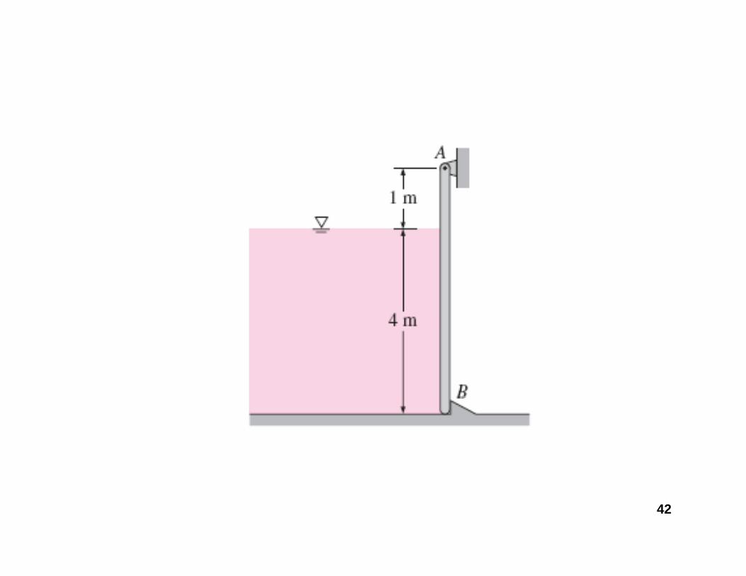
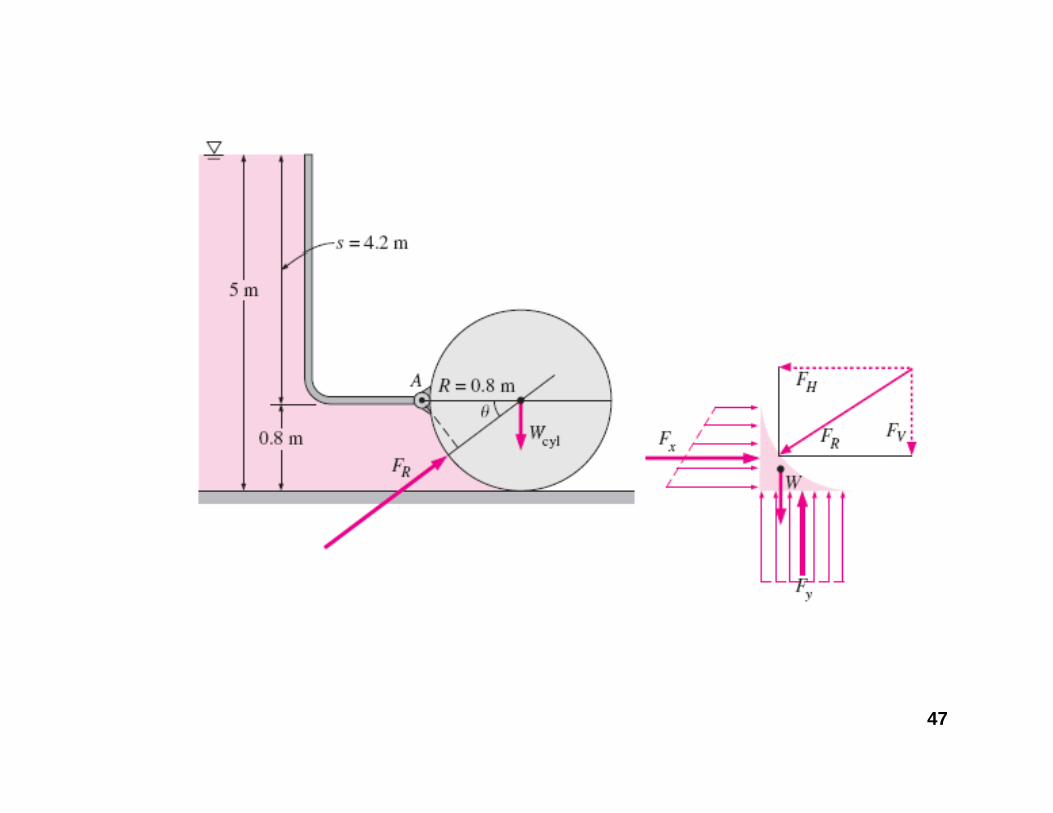
• Example: Find the vertical and horizontal forces on the given gateforces on the given gate(L=1 m).S l ti• Solution:
tV cV
48
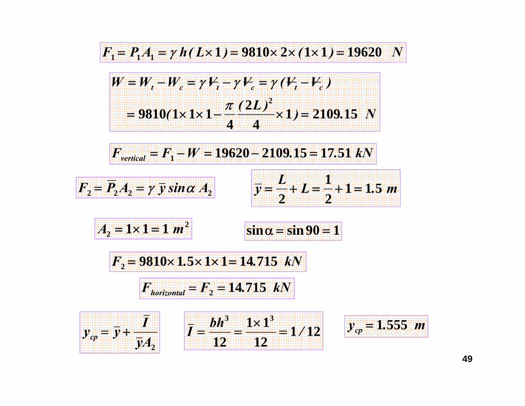
N)()L(hAPF 1962011298101111 =×××=×== γ
N.))L((
)VV(VVWWW ctctct
15210914
24
11198102
=×−××=
−=−=−=
π
γγγ
44
kN..WFFvertical 5117152109196201 =−=−=
L 12222 AsinyAPF αγ== m.LLy 511
21
2=+=+=
190sinsinα2111 mA =×= 190sinsin ==α2 111 mA =×=
kN..F 71514115198102 =×××=
Iyy += 12111 33
/bhI =×
== m.ycp 5551=
kN.FFhorizontal 715142 ==
492Ay
yycp += 1211212
/I === ycp

3.6: Buoyancyy y• Considering the
submerged body in the figure:Th f ti• The force acting on the lower surface of the body is equal tothe body is equal to the weight of the liquid needed to fill qthe volume above this surface.
50

Buoyancyy y• The force acting on
the upper surface ofthe upper surface of the body is equal to the weight of the gliquid above this surface. A body completely submerged in a liquid
• Summing the forces:
B up down fluid bodyF F F V= − = γ
51
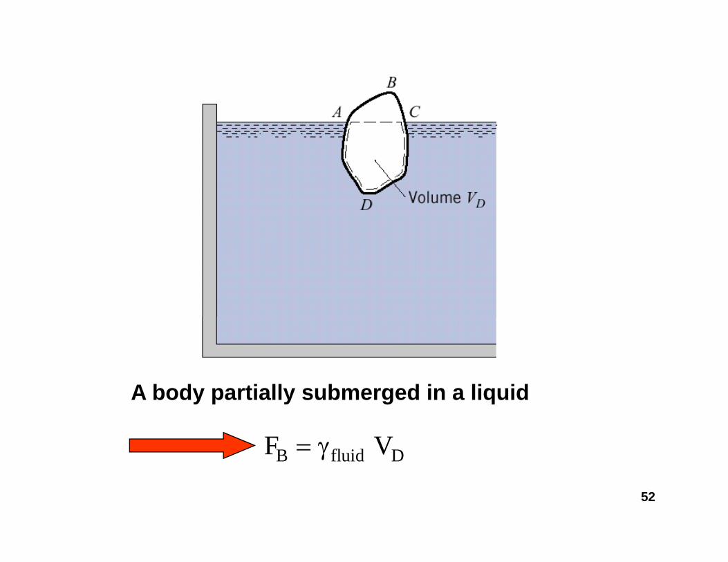
A b d ti ll b d i li idA body partially submerged in a liquid
B fluid DF V= γ
52
B fluid Dγ

Buoyancyy y
• Consequently, the buoyant force on a submerged body is equal to the weight of the liquid that would be needed to occupy the volume of the body.
• Similarly, for a floating body, the buoyant y, g y, yforce is equal to the weight of the liquid that would be needed to occupy the pysubmerged volume of the body.
53

Buoyancyy y
• This principle of buoyancy is basically what is commonly known as the Archimedes’ principle: “For an object partially or completely submerged in a fluid, there is a net upward force equal to the weight of the displaced fluid.”
• The buoyancy force is an upward force y y pthat passes through the centroid of the displaced volume.
54
p

Hydrometryy y• Device [glass bulb] to measure the γ or S of a
liquid based on the principle of buoyancy
55
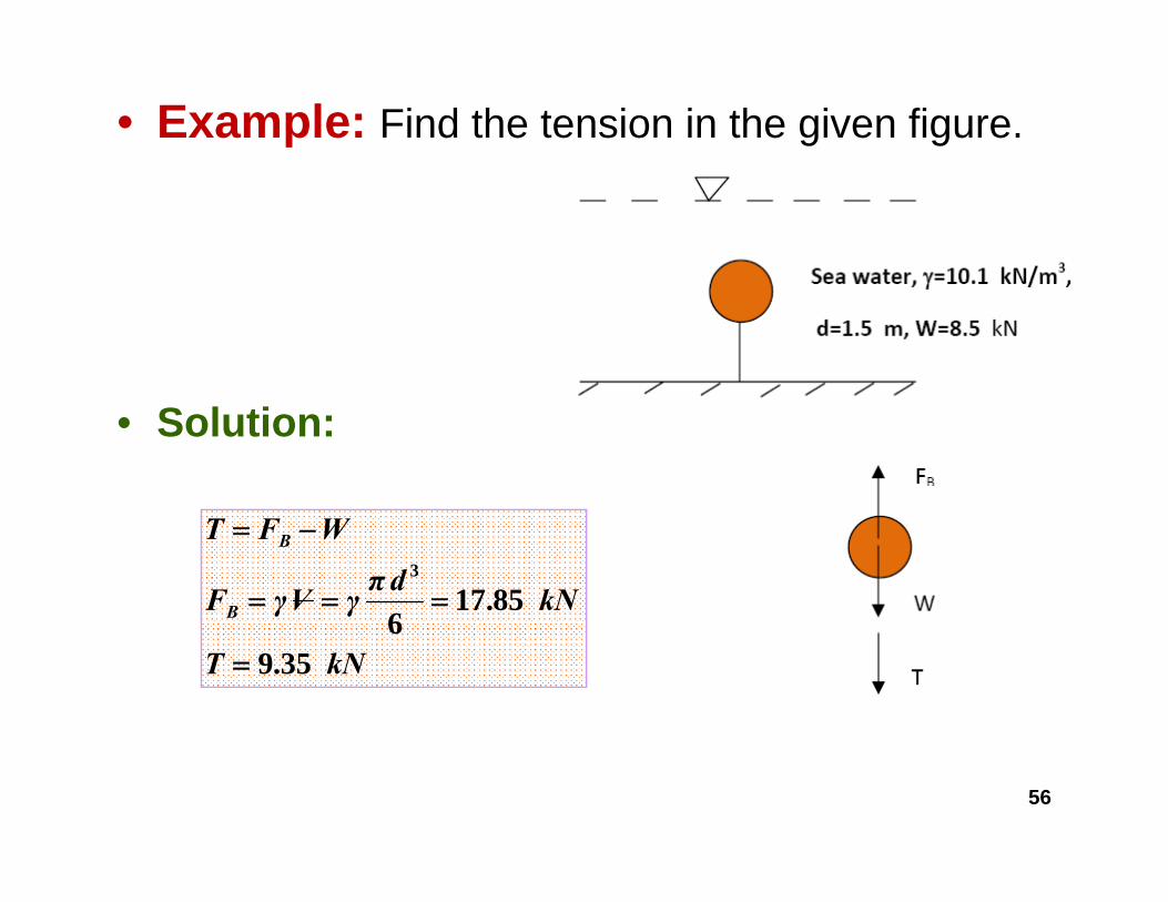
• Example: Find the tension in the given figure.
• Solution:
kN.dπγVγF
WFT
B
B
85176
3
===
−=
kN.T 3596
=
56
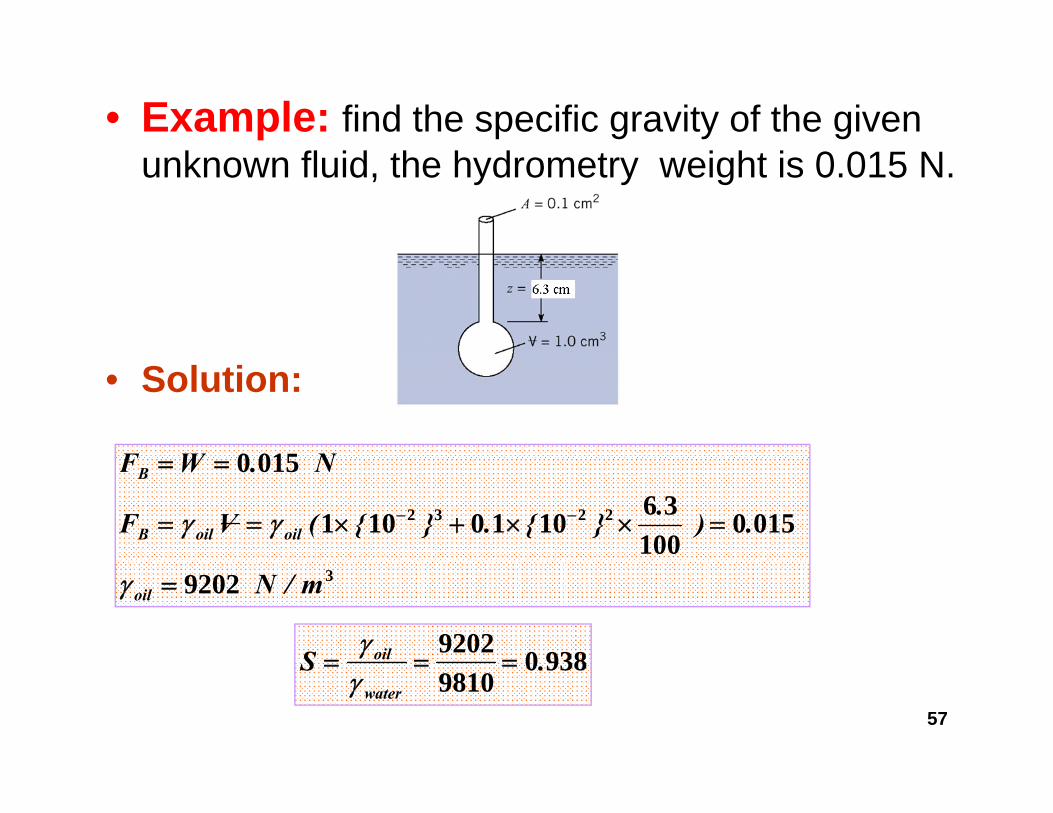
• Example: find the specific gravity of the given funknown fluid, the hydrometry weight is 0.015 N.
• Solution:
0150 NWF
2232 0150100
361010101
0150
.).}{.}{(VF
N.WF
oiloilB
B
=××+×==
==
−−γγ
39202 m/Noil =γ
93809202S oil ===γ
57
93809810
.Swater
===γ