ch 4: integrated optic waveguides integrated optics (optoelectronics, photonics) is the technology...
Post on 22-Dec-2015
243 views
TRANSCRIPT

Ch 4: Integrated Optic Ch 4: Integrated Optic WaveguidesWaveguides
Integrated optics Integrated optics (optoelectronics, photonics) (optoelectronics, photonics) is the technology of is the technology of constructing optic devices constructing optic devices & circuits on substrates& circuits on substrates
Within integrated structure, Within integrated structure, light is transformed through light is transformed through waveguideswaveguides
Dielectric slab waveguidesDielectric slab waveguides Light propagates in the filmLight propagates in the film

Dielectric slab waveguideDielectric slab waveguide
Critical angles at lower and upper Critical angles at lower and upper boundariesboundaries
11>largest of both>largest of both Surfaces must be smooth (specular)Surfaces must be smooth (specular) Material (film) homogenousMaterial (film) homogenous Absorption smallAbsorption small Typical materialsTypical materials Symmetrical and asymmetrical Symmetrical and asymmetrical
waveguideswaveguides

Dielectric slab waveguideDielectric slab waveguide
Propagation factorsPropagation factors
FieldsFields
Phase velocityPhase velocity Effective index of refractionEffective index of refraction
Evanescent fieldsEvanescent fields

Modes in the Symmetric WGModes in the Symmetric WG
nn22≤n≤neffeff≤n≤n11
Mode condition, Mode condition, =m2=m2 Cavity like conditionCavity like condition The waves supported by the waveguide are the The waves supported by the waveguide are the
modesmodes
TE & TM polarizations, ReflectionsTE & TM polarizations, Reflections
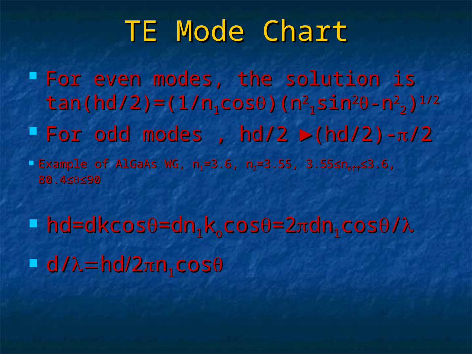
TE Mode ChartTE Mode Chart For even modes, the solution is For even modes, the solution is
tan(hd/2)=(1/ntan(hd/2)=(1/n11coscos)(n)(n2211sinsin22-n-n22
22))1/21/2
For odd modes , hd/2 For odd modes , hd/2 ►(►(hd/2)-hd/2)-/2/2 Example of AlGaAs WG, nExample of AlGaAs WG, n11=3.6, n=3.6, n22=3.55, 3.55≤n=3.55, 3.55≤neffeff≤3.6, ≤3.6,
80.4≤80.4≤≤90≤90
hd=dkcoshd=dkcos=dn=dn11kkoocoscos=2=2dndn11coscos//
d/d/hdhd22nn11coscos

TE Mode chartTE Mode chart
Note d/ ~ evanescent wave
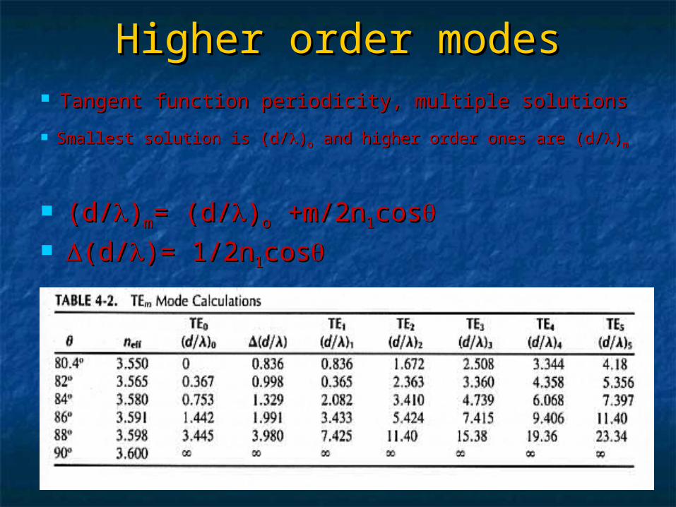
Higher order modesHigher order modes Tangent function periodicity, multiple solutionsTangent function periodicity, multiple solutions
Smallest solution is (d/Smallest solution is (d/))oo and higher order ones are (d/ and higher order ones are (d/))mm
(d/(d/))mm= (d/= (d/))oo +m/2n +m/2n11coscos (d/(d/)= 1/2n)= 1/2n11coscos

Multi modesMulti modes Example 4-1, using mode chartExample 4-1, using mode chart In the example 3 modes exist, higher modes are cut offIn the example 3 modes exist, higher modes are cut off
Cut off occurs when propagation angle for a given mode is just the Cut off occurs when propagation angle for a given mode is just the critical anglecritical angle
Condition for cut off for mth TE mode, (d/Condition for cut off for mth TE mode, (d/))m,cm,c= m/2 (n= m/2 (n2211-n-n22
22))1/21/2
If d/If d/< this value, mth mode will not propagate< this value, mth mode will not propagate

Multi modesMulti modes
Highest mode of a WG: Highest mode of a WG: m=2d (nm=2d (n22
11-n-n2222))1/21/2 / /
# of modes for a WG: # of modes for a WG: N=1+2d (nN=1+2d (n22
11-n-n2222))1/21/2 / /
For a single mode, TEFor a single mode, TEoo: : d/d/<1/2 (n<1/2 (n22
11-n-n2222))1/21/2
Multi mode WGMulti mode WG

TM mode chartTM mode chart Solution for phase condition for TM Solution for phase condition for TM
polarization: tan(hd/2)=(npolarization: tan(hd/2)=(n11/n/n2222coscos))
(n(n2211sinsin22-n-n22
22))1/21/2
For odd modes , hd/2 For odd modes , hd/2 ►(►(hd/2)-hd/2)-/2/2 For n1 close to n2, difference between TE and TM solutions is For n1 close to n2, difference between TE and TM solutions is
negligiblenegligible
Two modes having the same propagation factor are said to Two modes having the same propagation factor are said to be degeneratebe degenerate
Even when n1 is not close to n2, cut off values for TE and TM Even when n1 is not close to n2, cut off values for TE and TM modes are the samemodes are the same
It follows that # of modes is sameIt follows that # of modes is same Total # of modes is twice the valueTotal # of modes is twice the value Single mode operation?Single mode operation?

Mode patternMode pattern
Variation of light in Variation of light in transverse planetransverse plane
Fields outside filmFields outside film m: # of zero crossingsm: # of zero crossings High order modes:High order modes:
Steeper anglesSteeper angles Travel longerTravel longer Suffer greater absorptionSuffer greater absorption
Scattering might deflect them below Scattering might deflect them below critical anglecritical angle
Higher order modes attenuate more quickly Higher order modes attenuate more quickly than lower order modesthan lower order modes

Modes in Asymmetric WGModes in Asymmetric WG
The practical choiceThe practical choice Let nLet n11=2.29 (ZincSulfide) =2.29 (ZincSulfide)
nn22=1.5 (glass), n=1.5 (glass), n33=1 (air)=1 (air)
C1C1=25.9=25.9oo, , C2C2=41=41oo
nn22≤n≤neffeff≤n≤n11
Following similar solutions as Following similar solutions as before, mode chart resultsbefore, mode chart results

Mode Chart and PatternMode Chart and Pattern
TE and TM are not TE and TM are not degeneratedegenerate
Truly single mode Truly single mode operation is possibleoperation is possible
OIC are single mode, OIC are single mode, asymmetrical structuresasymmetrical structures
Mode patternsMode patterns
Unequal amplitude at Unequal amplitude at two boundariestwo boundaries
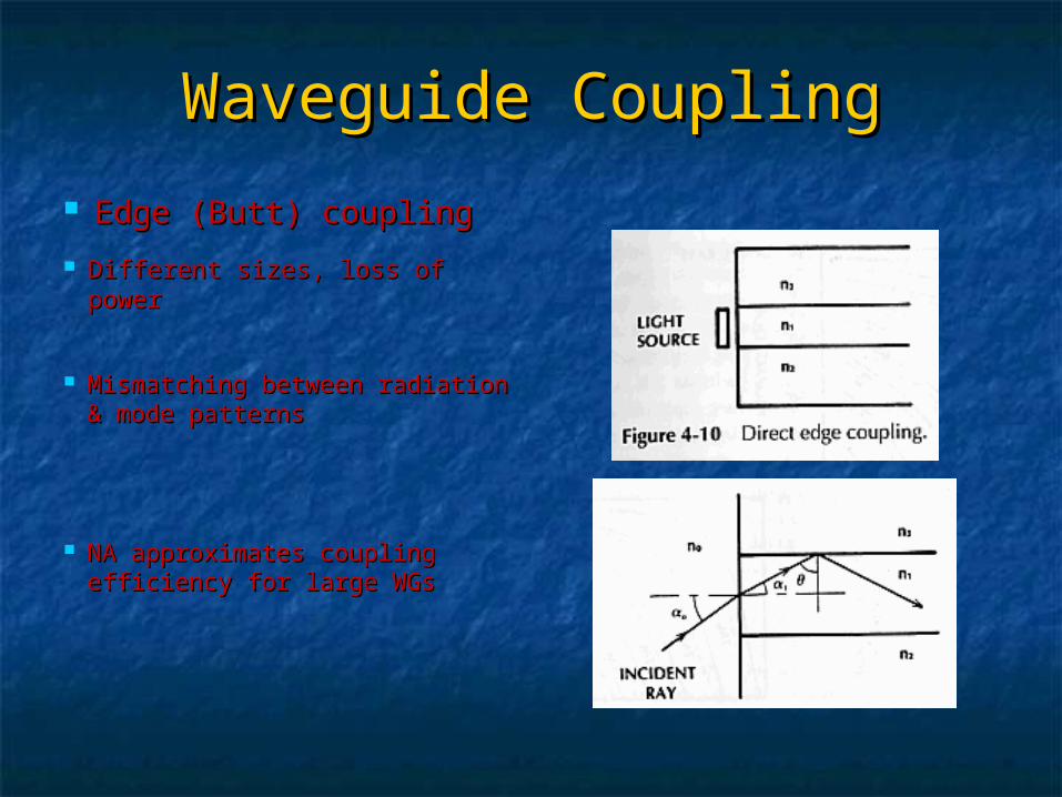
Waveguide CouplingWaveguide Coupling
Edge (Butt) couplingEdge (Butt) coupling Different sizes, loss of powerDifferent sizes, loss of power
Mismatching between radiation Mismatching between radiation & mode patterns& mode patterns
NA approximates coupling NA approximates coupling efficiency for large WGsefficiency for large WGs
Edge CouplingEdge Coupling
In single mode, pattern matching is critical In single mode, pattern matching is critical in determining the coupling efficiencyin determining the coupling efficiency
=(n=(n11-n-n22)/n)/n11 ► NA=n► NA=n11(2 (2 ))1/21/2 when when
indices close to each otherindices close to each other Transmission loss @ plane Transmission loss @ plane
boundaries (15%)boundaries (15%) Advantages: Compactness, simplicityAdvantages: Compactness, simplicity When WG is small, lens used to reduce beam When WG is small, lens used to reduce beam ►►
creates an alignment problemcreates an alignment problem

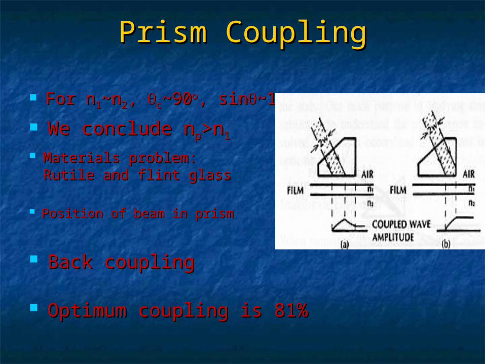
Prism CouplingPrism Coupling
When nWhen n33=1=1 Frustrated total internal Frustrated total internal
reflectionreflection
Field added must Field added must be in phase with be in phase with field inside or field inside or supported by WGsupported by WG
nnppsinsinpp= n= n11sinsin
pp is adjusted to make matching is adjusted to make matching (synchronous)(synchronous)
Prism CouplingPrism Coupling
For nFor n11~n~n22, , cc~90~90oo, sin, sin~1~1 We conclude nWe conclude npp>n>n11
Materials problem: Materials problem: Rutile and flint glassRutile and flint glass
Position of beam in prismPosition of beam in prism
Optimum coupling is 81%Optimum coupling is 81%
Back couplingBack coupling
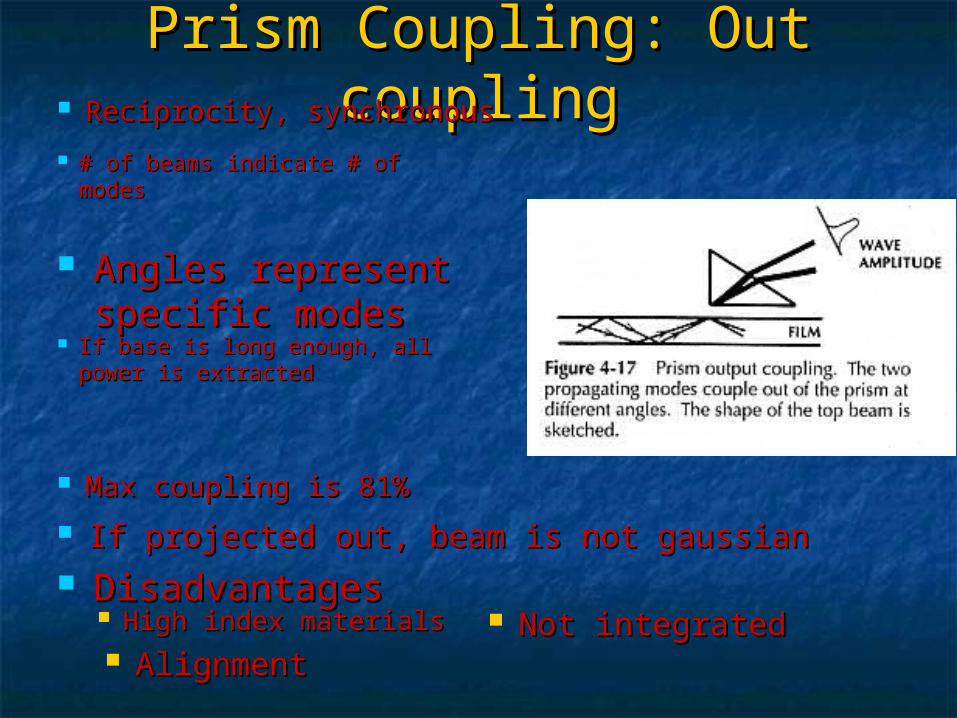
Prism Coupling: Out Prism Coupling: Out couplingcoupling Reciprocity, synchronousReciprocity, synchronous
# of beams indicate # of modes# of beams indicate # of modes
Angles represent Angles represent specific modesspecific modes
If base is long enough, all power If base is long enough, all power is extractedis extracted
If projected out, beam is not gaussianIf projected out, beam is not gaussian
Max coupling is 81%Max coupling is 81%
DisadvantagesDisadvantages High index materialsHigh index materials AlignmentAlignment
Not integratedNot integrated

Grating CouplingGrating Coupling Amplitude or phase Amplitude or phase
periodic structureperiodic structure Longitudinal propagation Longitudinal propagation
factor matchingfactor matching
Position of beam to grating (to Position of beam to grating (to prevent back coupling)prevent back coupling)
Gaussian beam max efficiency is Gaussian beam max efficiency is 81%81%
Waveguide dispersionWaveguide dispersion
Mode chart shows dependence of nMode chart shows dependence of neffeff on on just similar to n( just similar to n())
This nThis neffeff ( ( is called waveguide dispersion is called waveguide dispersion
It follows same eq. as material dispersion: It follows same eq. as material dispersion: ((/L)=-M/L)=-Mgg, where , where is source linewidthis source linewidth

Modal DistortionModal Distortion Not wavelength dependantNot wavelength dependant
If If =0, modal =0, modal distortion does existdistortion does exist
Single mode, no Single mode, no modal distortionmodal distortion
Consider shortest (along Consider shortest (along axis) and longest (along axis) and longest (along qc) paths, and find their qc) paths, and find their travel time differencetravel time difference
Axial ray, tAxial ray, taa=n=n11L/CL/C Critical angle ray, tCritical angle ray, tcc=n=n22
11L/CnL/Cn22
/L)=n/L)=n11(n(n11 – n – n22)/Cn)/Cn22=n=n11/C/C