ch 6 interchanges and ramps - home | kytc studies and reports... · this chapter summarizes...
TRANSCRIPT

Chapter VI – Interchanges and Ramps
I-69 Corridor Planning Study, Eddyville to Henderson 6-1
Interchanges have design guidelines for design speed, typical sections, horizontal and vertical alignment that are similar to mainline sections, along with added requirements for merge and weaving sections.
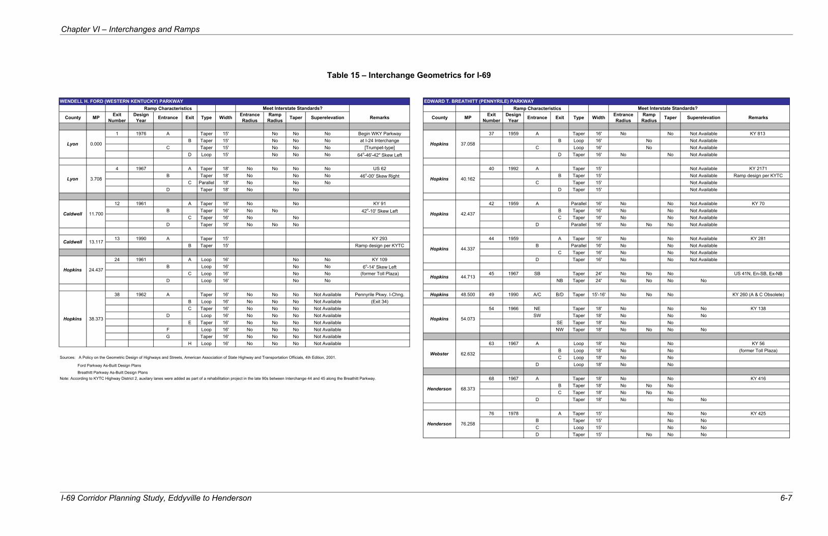
VI. INTERCHANGES AND RAMPS There are a total of sixteen (16) interchanges along the I-69 study corridor. Of these sixteen (16) interchanges, six (6) are located on the Ford Parkway and ten (10) are on the Breathitt Parkway. This chapter summarizes interchange and ramp conditions, taken from the as-built design plans, and compares those conditions with AASHTO guidelines for several key areas. These findings are identified in Figures 15 through 19 and Table 15. The figures show interchange data only for elements that do not meet the recommended guidelines. In the guidelines recommended by AASHTO, there is some degree of variability and options that are available to designers to alter a specific set of standards that are established for interchange and ramp features. Therefore, without a more comprehensive evaluation of the features and characteristics at each location, it is difficult to conclusively determine the applicable minimum standards and the degree to which existing conditions adhere to those standards. Nevertheless, this chapter establishes basic assumptions related to various design features at interchanges and ramps and makes a general determination as to whether minimum guidelines are achieved at each location. A. Design Speed AASHTO minimum design speeds for entrance and exit ramps are 40 MPH for directional ramps, 35 MPH for semi-directional ramps in rural areas and 25 MPH for semi-directional ramps in urban areas. For loop ramps, 25 MPH minimum guidelines are recommended for both rural and urban areas. For horizontal alignment of directional, semi-directional ramps and loop ramps with 40 MPH, 35 MPH and 25 MPH design speeds, respectively, the corresponding minimum radii are 465’, 350' and 170'. The design speed was not available for some ramps on the as-built plans; however, a cursory evaluation indicates that the radii of many of the ramps do not meet the minimum guidelines for the recommended design speed. Therefore, although there was insufficient information to definitively locate or quantify where these possible variations exist, many of the ramps do not meet the minimum guidelines for design speed.

Figure 15. Substandard Interchange Conditions for Lyon County 6-2Note: Data is shown only for elements that do not meet recommended guidelines.

Note: Data is shown only for elements that do not meet recommended guidelines. Figure 16. Substandard Interchange Conditions for Caldwell County 6-3

Figure 17. Substandard Interchange Conditions for H
opkins County 6-4 Note: Data is shown only for elements that
do not meet recommended guidelines.

Figure 18. Substandard Interchange Conditions for W
ebster County 6-5 Note: Data is shown only for elements that
do not meet recommended guidelines.

Figure 19. Substandard Interchange Conditions for H
enderson County 6-6
Note: Data is shown only for elements that do not meet recommended guidelines.
Chapter VI – Interchanges and Ramps
I-69 Corridor Planning Study, Eddyville to Henderson 6-7
Table 15 – Interchange Geometrics for I-69
Ramp Characteristics Ramp Characteristics
County MP Exit Number
Design Year Entrance Exit Type Width Entrance
RadiusRamp
Radius Taper Superelevation Remarks County MP Exit Number
Design Year Entrance Exit Type Width Entrance
RadiusRamp
Radius Taper Superelevation Remarks
1 1976 A Taper 15' No No No Begin WKY Parkway 37 1959 A Taper 16' No No Not Available KY 813 B Taper 15' No No No at I-24 Interchange B Loop 16' No Not Available
C Taper 15' No No No [Trumpet-type] C Loop 16' No Not AvailableD Loop 15' No No No 64o-46'-42" Skew Left D Taper 16' No No Not Available
4 1967 A Taper 18' No No No No US 62 40 1992 A Taper 15' Not Available KY 2171B Taper 18' No No No 46o-00' Skew Right B Taper 15' Not Available Ramp design per KYTC
C Parallel 18' No No No C Taper 15' Not AvailableD Taper 18' No No D Taper 15' Not Available
12 1961 A Taper 16' No No KY 91 42 1959 A Parallel 16' No No Not Available KY 70B Taper 16' No No 42o-10' Skew Left B Taper 16' No No Not Available
C Taper 16' No No C Taper 16' No No Not AvailableD Taper 16' No No No D Parallel 16' No No No Not Available
13 1990 A Taper 15' KY 293 44 1959 A Taper 16' No No Not Available KY 281B Taper 15' Ramp design per KYTC B Parallel 16' No No Not Available
C Taper 16' No No Not Available24 1961 A Loop 16' No No KY 109 D Taper 16' No No Not Available
B Loop 16' No No 6o-14' Skew LeftC Loop 16' No No (former Toll Plaza) 45 1967 SB Taper 24' No No No US 41N, En-SB, Ex-NB
D Loop 16' No No NB Taper 24' No No No No
38 1962 A Taper 16' No No No Not Available Pennyrile Pkwy. I-Chng. Hopkins 48.500 49 1990 A/C B/D Taper 15'-16' No No No KY 260 (A & C Obsolete)B Loop 16' No No No Not Available (Exit 34)C Taper 16' No No No Not Available 54 1966 NE Taper 18' No No No KY 138
D Loop 16' No No No Not Available SW Taper 18' No No NoE Taper 16' No No No Not Available SE Taper 18' No No
F Loop 16' No No No Not Available NW Taper 18' No No No NoG Taper 16' No No No Not Available
H Loop 16' No No No Not Available 63 1967 A Loop 18' No No KY 56B Loop 18' No No (former Toll Plaza)
Sources: A Policy on the Geometric Design of Highways and Streets, American Association of State Highway and Transportation Officials, 4th Edition, 2001. C Loop 18' No NoFord Parkway As-Built Design Plans D Loop 18' No NoBreathitt Parkway As-Built Design Plans
Note: According to KYTC Highway District 2, auxilary lanes were added as part of a rehabilitation project in the late 90s between Interchange 44 and 45 along the Breathitt Parkway. 68 1967 A Taper 18' No No KY 416B Taper 18' No No NoC Taper 18' No No No
D Taper 18' No No No
76 1978 A Taper 15' No No KY 425B Taper 15' No NoC Loop 15' No NoD Taper 15' No No No
WENDELL H. FORD (WESTERN KENTUCKY) PARKWAY EDWARD T. BREATHITT (PENNYRILE) PARKWAY
Henderson
13.117
44.713Hopkins
Caldwell
Hopkins 38.373
76.258
Hopkins
Lyon
Caldwell
Hopkins
3.708
11.700
24.437
Hopkins
Hopkins
Hopkins
62.632
68.373
Webster
Henderson
40.162
42.437
44.337
54.073
Meet Interstate Standards? Meet Interstate Standards?
Lyon 0.000 37.058Hopkins

Chapter VI – Interchanges and Ramps
I-69 Corridor Planning Study, Eddyville to Henderson 6-8
B. Typical Sections The following is a summary of existing typical section design elements (lane widths and shoulder widths) on the interchange ramps and a comparison of these elements with current AASHTO guidelines. 1. Lane Widths The minimum AASHTO guideline for lane width along an interchange ramp is 15 feet. The lane widths on all existing exit ramps throughout the entire corridor range in width from 15 feet at the I-24 Interchange in Lyon County to 18 feet at the KY 416 Interchange in Henderson County. Therefore, the lane width on the interchange ramps meets the minimum AASHTO guidelines for freeway design. A summary of ramp widths is presented in Table 15. 2. Shoulder Widths AASHTO design guidelines recommend shoulders on entrance and exit ramps that could be used for emergency stopping and to minimize the effect of breakdowns. Curbs should only be used where adverse drainage conditions might exist. Most typical sections in the existing plans indicate that raised mountable curbs were used on the entrance and exit ramps. Other than the width provided for the ramp itself, there was no additional width provided for shoulders. Therefore, the ramps do not meet AASHTO guidelines for shoulders.
C. Alignment Geometry The following is a summary of the geometry of the as-built ramp configurations as compared to the current AASHTO guidelines. 1. Horizontal Alignment
Many of the directional, semi-directional and loop ramps at the existing interchanges do not meet the recommended minimum design guidelines for horizontal alignment. At the interchanges, the maximum degree of curve on most of the existing interchange ramps exceeds the design standard of 465’ minimum radius for directional type ramps, 350’ minimum radius for semi-directional type ramps in rural areas and 170’ minimum radius for semi-directional type ramps in urban areas and for loop type ramps. Ramp locations that exceed the minimum horizontal design standards appear in Table 15. 2. Superelevation Rate
The recommended maximum superelevation rate for ramp configurations is 8 percent. Many of the directional and loop ramps have superelevations that exceed the 8% maximum. The ramp locations which exceed the maximum recommended rate are shown in Table 15.

Chapter VI – Interchanges and Ramps
I-69 Corridor Planning Study, Eddyville to Henderson 6-9
Entrance ramps and exit ramps at many interchanges along the two Parkways do not appear to meet minimum interstate guidelines for lengths and tapers.
3. Vertical Alignment
The as-built plan sets do not provide vertical profile information for ramps. However, it is not anticipated that significant vertical alignment problems exist along the Parkways. D. Speed-Change Lanes and Weaving Characteristics The following is a summary of the geometry of the as-built ramp configurations as compared to the current AASHTO guidelines for speed-change lanes and weaving areas. 1. Speed-Change Lanes Perhaps the single most important factor affecting safety and operational efficiency at interchanges is the effective design of the speed-change lanes (entrance and exit ramps). The two typical types of speed-change lanes include the parallel type and the taper type. These design types can be applied to entrance or exit ramps. Operational studies have shown that the minimum desirable rate of taper for taper type entrance ramps is 50:1 between the outer edge of the acceleration lane and the edge of the through-traffic lane. The length of parallel type entrance ramp required to accelerate to highway speed is dependent on the actual design speed of the mainline roadway. However, if the length of acceleration length exceeds 1300', the use of a taper type is recommended. Where a parallel type ramp is used, the taper length at the downstream end of the lane should be 25:1. Exit ramp configurations are also described as taper type or parallel type. The taper type ramps are generally designed with an alignment break at the outer edge of pavement with a divergence angle of 2 to 5 degrees. The parallel type begins with an exit taper of 20:1 and the length of parallel lane is dependent on the design speed of the mainline roadway. Existing entrance ramps on the Ford and Breathitt Parkways do not meet the minimum guideline of 50:1 entrance tapers, and existing exit ramps have exit taper lengths that do not meet the minimum taper length of 20:1. The minimum deceleration length for exit ramps to a stop condition is 615 feet. None of the current directional exit ramps meets this criterion on either Parkway. In addition to the entrance and exit ramp taper lengths, the initial ramp curvatures do not meet the minimum radius of 230 feet.

Chapter VI – Interchanges and Ramps
I-69 Corridor Planning Study, Eddyville to Henderson 6-10
2. Weaving Characteristics The minimum length of weaving section recommended for a service-to-service interchange is 1,000 feet. There are three (3) interchanges where the length of weaving is below that recommended in the AASHTO guidelines. Two of those interchanges are on the Ford Parkway: KY 109 at MP 24.437 in Hopkins County and the Breathitt Parkway at MP 38.373 in Hopkins County. The third is the KY 56 interchange on the Breathitt Parkway at MP 62.632 in Webster County. The interchanges at MP 24.437 on the Ford Parkway in Hopkins County and MP 62.632 on the Breathitt Parkway in Webster County were initially designed for toll collection stations. The configurations included short weaving sections on the mainline of approximately 300 feet. The design was adequate to serve the toll facility, where low speeds were prevalent. However, although the toll collection operations have since been suspended, the initial interchange configurations were never upgraded to accommodate the resulting higher speeds. E. Interchange Crash Data Crashes at interchanges along the study section of the Parkways were also considered as part of this analysis. Crashes occurring within a 0.1-mile section on either side of the intersecting route at each interchange were summarized by crash type, as shown in Table 16. Along the Parkways, there are three interchanges that fall within the high crash segments identified previously in Sections 4 and 5 of Chapter 3:
• Exit 1 in Lyon County, at the interchange with I-24, had 11 crashes in the period studied. Five (5) of these were crashes with an animal.
• Exit 4 in Lyon County, at the interchange with US 62, had 6 crashes in the period studied. Five (5) of these were crashes with a fixed object.
• Exit 42 in Hopkins County, at the interchange with KY 70/85, had 65 crashes in the period studied. The majority of these crashes (37) were ramp-related and another 20 were rear-end crashes in the travel lanes.
Two other interchanges along the Parkways had a high number of crashes within 0.1-miles of the intersecting route. These include:
• Exit 37 in Hopkins County, at the interchange with KY 813, had a total of 21 crashes. Half of these (10) were crashes with a fixed object.
• Exit 44 in Hopkins County, at the interchange with KY 281, had 34 crashes in the period studied. Fourteen (14) of these were rear-end crashes and another 12 were ramp-related.
Crash types at interchanges can be studied to identify potential design and geometric problems with entrance ramps, exit ramps and bridge clearances. The number of ramp, rear-end and fixed-object crashes at interchanges may indicate the need for entrance, exit and clearance improvements at certain interchanges along both Parkways.

Chapter VI – Interchanges and Ramps
I-69 Corridor Planning Study, Eddyville to Henderson 6-11
Table 16 - Interchange Crash Data
Number of Crashes by Type 1
Exit Number County Intersecting Route Ramp Rear-
End Fixed Object Animal Sideswipe
Ran Off
RoadOther
Total Crashes
Ford Parkway 42 Lyon I-24 1 0 2 5 1 0 2 11 4 Lyon US 62 0 0 5 0 0 0 1 6 12 Caldwell KY 91 0 0 1 1 0 0 0 2 13 Caldwell KY 293 2 0 1 1 0 1 0 5 24 Hopkins KY 109 2 1 1 1 0 0 0 5 38 Hopkins Breathitt Parkway 0 0 4 0 0 0 1 5
Breathitt Parkway
37 Hopkins KY 813 2 1 10 0 5 1 2 21 40 Hopkins KY 2171 0 0 0 0 0 0 2 2 42 Hopkins KY 70 37 20 3 3 1 0 1 65 44 Hopkins KY 281 12 14 2 0 2 3 1 34 45 Hopkins US 41 0 1 1 2 0 0 1 5 49 Hopkins KY 260 0 0 1 1 0 1 0 3 54 Hopkins KY 138 0 0 3 1 0 1 3 8 63 Webster KY 56 2 1 4 0 1 1 0 9 68 Henderson KY 416 0 0 0 1 0 0 2 3 76 Henderson KY 425 1 1 1 0 0 0 1 4
1 Number of crashes in period studied (1998-2001), within 0.1 mile on either side of intersecting route.