ch. 9_geologic hazard; landslides and other slope failures
TRANSCRIPT

8/12/2019 CH. 9_Geologic Hazard; Landslides and Other Slope Failures
http://slidepdf.com/reader/full/ch-9geologic-hazard-landslides-and-other-slope-failures 1/136
PART III
Geologic Hazards
Purpose and Scope
Part III sets forth the basis for recognizing, understanding, and treating the geologic haz-ards to provide for safe and economical construction. It invokes general concepts ratherthan rigorous mathematical analyses.
Significance
Geologic hazards represent substantial danger to humans and their works. The hazards mayexist as a consequence of natural events, but often they are the result of human activities.
Slope failures, such as landslides and avalanches, can occur in almost any hilly or moun-
tainous terrain, or offshore, often with a very frequent incidence of occurrence, and can bevery destructive, at times catastrophic. The potential for failure is identifiable, and there-fore forewarning is possible, but the actual time of occurrence is not predictable. Mostslopes can be stabilized, but under some conditions failure cannot be prevented by rea-sonable means.
Ground subsidence, collapse, and expansion usually are the result of human activities andrange from minor to major hazards, although loss of life is seldom great as a consequence.Their potential for occurrence evaluated on the basis of geologic conditions, is for the mostpart readily recognizable and they are therefore preventable or their consequences areavoidable.
Earthquakes represent the greatest hazard in terms of potential destruction and loss of life.They are the most difficult hazard to assess in terms of their probability of occurrence andmagnitude as well as their vibrational characteristics, which must be known for aseismic
697
opyright 2005 by Taylor & Francis Group

8/12/2019 CH. 9_Geologic Hazard; Landslides and Other Slope Failures
http://slidepdf.com/reader/full/ch-9geologic-hazard-landslides-and-other-slope-failures 2/136
design of structures. Recognition of the potential on the basis of geologic conditions andhistorical events provides the information for aseismic design.
Floods (Chapter 8) have a high frequency of occurrence, and under certain conditionscan be anticipated. Protection is best provided by avoiding potential flood areas, which isnot always practical. Prevention is possible under most conditions, but often at substan-tial costs.
Health hazards related to geologic conditions include asbestos, silica and radon, and thevarious minerals found in groundwater such as arsenic and mercury. Recently, mold has
been added to the list of health hazards. Discussion of environmental concerns related tohealth from contaminants are beyond the scope of this book.
698 Geotechnical Engineering Investigation Handbook, Second Edition
opyright 2005 by Taylor & Francis Group
8/12/2019 CH. 9_Geologic Hazard; Landslides and Other Slope Failures
http://slidepdf.com/reader/full/ch-9geologic-hazard-landslides-and-other-slope-failures 3/136
9Landslides and Other Slope Failures
9.1 Introduction
9.1.1 General
Origins and Consequences of Slope Failures Gravitational forces are always acting on a mass of soil or rock beneath a slope. As long as thestrength of the mass is equal to or greater than the gravitational forces, the forces are in bal-ance, the mass is in equilibrium, and movement does not occur. An imbalance of forces resultsin slope failure and movement in the forms of creep, falls, slides, avalanches, or flows.
Slope failures can range from being a temporary nuisance by partially closing a road-way, to destroying structures, to being catastrophic and even burying cities.
Failure Oddities
● Prediction: Some failures can be predicted, others cannot, although most haz-ardous conditions are recognizable.
● Occurrence: Some forms occur without warning; many other forms give warning,most commonly in the form of early surface cracks.
● Movement velocities: Some move slowly, others progressively or retrogressively,others at great velocities.
● Movement distances: Some move short distances; others can move for many miles.● Movement volume: Some involve small blocks; others involve tremendous volumes.● Failure forms: Some geologic formations have characteristic failure forms; others
can fail in a variety of forms, often complex.●
Mathematical analysis: Some conditions can be analyzed mathematically, manycannot.● Treatments : Some conditions cannot be treated to make them stable; they should
be avoided.
Objectives The objectives of this chapter are to provide the basis for:
● Prediction of slope failures through the recognition of the geologic and otherfactors that govern failure
● Treatment of slopes that are potentially unstable and pose a danger to someexisting development
● Design and construction of stable cut slopes and sidehill fills● Stabilization of failed slopes
699
opyright 2005 by Taylor & Francis Group

8/12/2019 CH. 9_Geologic Hazard; Landslides and Other Slope Failures
http://slidepdf.com/reader/full/ch-9geologic-hazard-landslides-and-other-slope-failures 4/136
9.1.2 Hazard Recognition
General Slope failures occur in many forms. There is a wide range in their predictability, rapidityof occurrence and movement, and ground area affected, all of which relate directly to the
consequences of failure. Recognition permits the selection of some slope treatment whichwill either avoid, eliminate, or reduce the hazard.Hazard recognition and successful treatment require thorough understanding of a num-
ber of factors including:
● Types and forms of slope failures (classification)● Relationship between geologic conditions and the potential failure form● Significance of slope activity, or amount and rate of movement● Elements of slope stability● Characteristics of slope failure forms (see Section 9.2)● Applicability of mathematical analysis (see Section 9.3 )
Classification of Slope Failures A classification of slope failures is given in Table 9.1. The most important classes are falls,slides, avalanches, and flows.
700 Geotechnical Engineering Investigation Handbook, Second Edition
TABLE 9.1A Classification of Slope Failures
Type Form Definition
Falls Free fall Sudden dislodgment of single or multiple blocks of soil or rock which fall infree descent
Topple Overturning of a rock block about a pivot point located below its center ofgravity
Slides Rotational Relatively slow movement of an essentially coherent block (or blocks) of soil,or slump rock, or soil–rock mixtures along some well-defined arc-shaped failure surface
Planar or Slow to rapid movement of an essentially coherent block (or blocks) of soil ortranslational rock along some well-defined planar failure surface.
SubclassesBlock glide A single block moving along a planar surface.Wedges Block or blocks moving along intersecting planar surfacesLateral A number of intact blocks moving as separate units with differing displacements
spreadingDebris slide Soil–rock mixtures moving along a planar rock surface
Avalanches Rock or Rapid to very rapid movement of an incoherent mass of rock or soil–rock debrisdebris wherein the original structure of the formation is no longer discernible,
occurring along an ill-defined surface.Flows Debris Soil or soil–rock debris moving as a viscous fluid or slurry, usually terminating
Sand at distances far beyond the failure zone; resulting from excessive poreSilt pressures (subclassed according to material type)MudSoil
Creep Slow, imperceptible downslope movement of soil or soil–rock mixtures.
Solifluction See Shallow portions of the regolith moving downslope at moderate to slow rates inSection 7.7.3 Arctic to sub-Arctic climates during periods of thaw over a surface usuallyconsisting of frozen ground
Complex Involves combinations of the above, usually occurring as a change from one formto another during failure with one form predominant
opyright 2005 by Taylor & Francis Group

8/12/2019 CH. 9_Geologic Hazard; Landslides and Other Slope Failures
http://slidepdf.com/reader/full/ch-9geologic-hazard-landslides-and-other-slope-failures 5/136
Major factors of classification include:● Movement form: Fall, slide, slide flow (avalanche), flow● Failure surface form: Arc-shaped, planar, irregular, ill-defined● Mass coherency: Coherent, with the original structure essentially intact although
dislocated, or incoherent, with the original structure totally destroyed● Constitution : Single or multiple blocks, or a heterogeneous mass without blocks,or a slurry
● Failure cause: Tensile strength or shear strength exceeded along a failure surface,or hydraulic excavation, or excessive seepage forces
Other factors to consider include:
● Mass displacement: Amount of displacement from the failure zone, which canvary from slight to small, to very large. Blocks can move together with similardisplacements, or separately with varying displacements.
● Material type: Rock blocks or slabs, soil–rock mixtures (debris), sands, silts, blocksof overconsolidated clays, or mud (weak cohesive soils).
● Rate of movement during failure: Varies from extremely slow and barely percepti- ble to extremely rapid as given in Table 9.2.
Landslides and Other Slope Failures 701
TABLE 9.2 Velocity of Movement for Slope Failure Forms a
Velocity(m/s) Movement Rate Classification
Extermely rapid
Very rapid
Rapid
Moderate
Slow
Very slow
Extremely slow10−9
10−8
10−7
10−6
10−5
10−4
10−3
10−2
10−1
1
10
102
3 m/sec
0.3 m/min
1.5 m/day
1.5 m/month
1.5 m/year
0.3 m/5 year
Avalanches and flows
Slides
Creep
F i n a l s t a g e
F i n a l s t a g e
E a r l y s t a g e
( R o t a t i o n a l s l i d e )
( P l a n a r s l i d e - r o c k m a s s )
I n t e r -
m e d
i a t e
a After Varnes, D. J., Landslides and Engineering Practice, Eckel, E. B., Ed., Highway ResearchBoard Special Report No. 29, Washington, DC, 1958. Reprinted with permission of theTransportation Research Board.
opyright 2005 by Taylor & Francis Group
8/12/2019 CH. 9_Geologic Hazard; Landslides and Other Slope Failures
http://slidepdf.com/reader/full/ch-9geologic-hazard-landslides-and-other-slope-failures 6/136
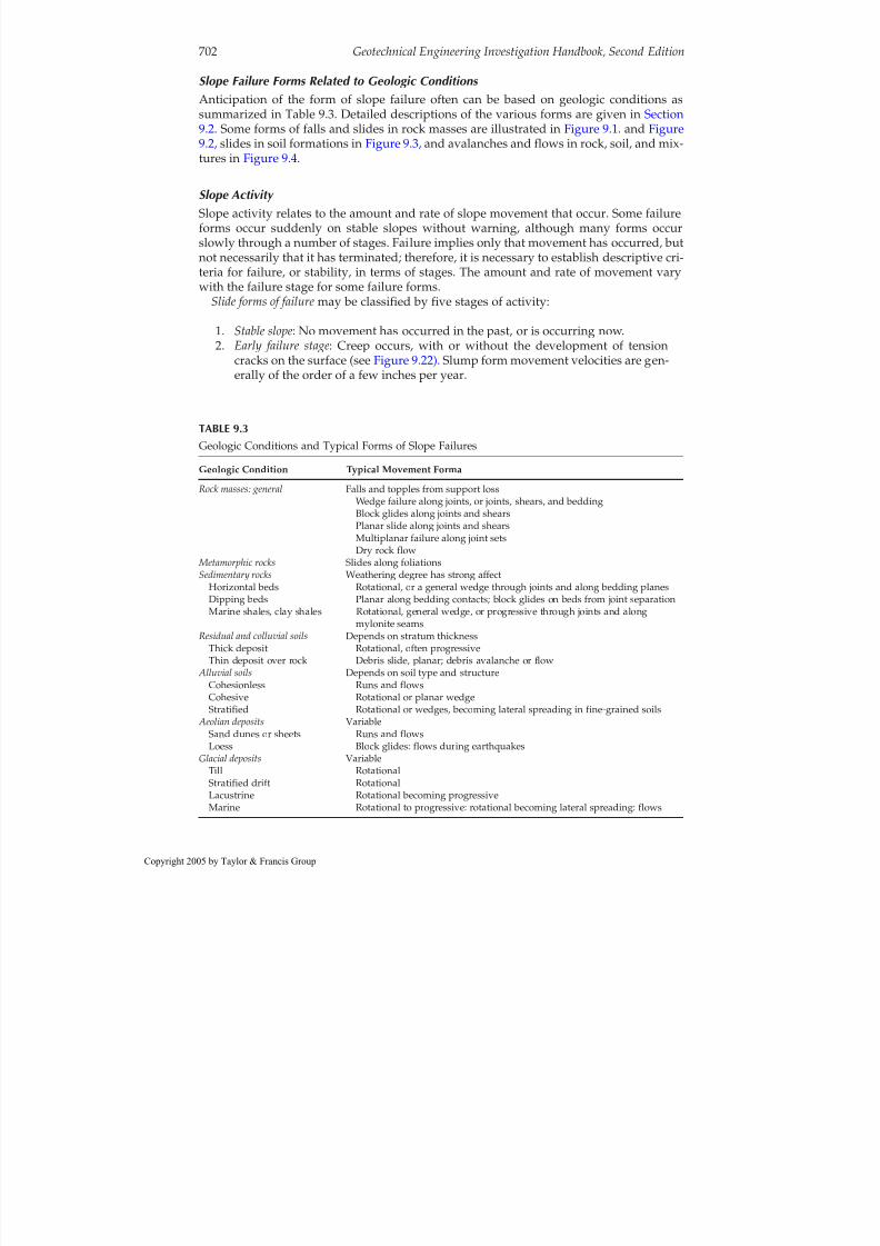
Slope Failure Forms Related to Geologic Conditions Anticipation of the form of slope failure often can be based on geologic conditions assummarized in Table 9.3. Detailed descriptions of the various forms are given in Section9.2. Some forms of falls and slides in rock masses are illustrated in Figure 9.1. and Figure9.2, slides in soil formations in Figure 9.3, and avalanches and flows in rock, soil, and mix-tures in Figure 9.4 .
Slope Activity Slope activity relates to the amount and rate of slope movement that occur. Some failureforms occur suddenly on stable slopes without warning, although many forms occurslowly through a number of stages. Failure implies only that movement has occurred, butnot necessarily that it has terminated; therefore, it is necessary to establish descriptive cri-teria for failure, or stability, in terms of stages. The amount and rate of movement varywith the failure stage for some failure forms.
Slide forms of failuremay be classified by five stages of activity:
1. Stable slope: No movement has occurred in the past, or is occurring now.2. Early failure stage: Creep occurs, with or without the development of tension
cracks on the surface (see Figure 9.22) . Slump form movement velocities are gen-erally of the order of a few inches per year.
702 Geotechnical Engineering Investigation Handbook, Second Edition
TABLE 9.3Geologic Conditions and Typical Forms of Slope Failures
Geologic Condition Typical Movement Forma
Rock masses: general Falls and topples from support lossWedge failure along joints, or joints, shears, and beddingBlock glides along joints and shearsPlanar slide along joints and shearsMultiplanar failure along joint setsDry rock flow
Metamorphic rocks Slides along foliationsSedimentary rocks Weathering degree has strong affect
Horizontal beds Rotational, or a general wedge through joints and along bedding planesDipping beds Planar along bedding contacts; block glides on beds from joint separationMarine shales, clay shales Rotational, general wedge, or progressive through joints and along
mylonite seamsResidual and colluvial soils Depends on stratum thickness
Thick deposit Rotational, often progressiveThin deposit over rock Debris slide, planar; debris avalanche or flow
Alluvial soils Depends on soil type and structureCohesionless Runs and flowsCohesive Rotational or planar wedgeStratified Rotational or wedges, becoming lateral spreading in fine-grained soils
Aeolian deposits VariableSand dunes or sheets Runs and flowsLoess Block glides: flows during earthquakes
Glacial deposits VariableTill RotationalStratified drift RotationalLacustrine Rotational becoming progressiveMarine Rotational to progressive: rotational becoming lateral spreading: flows
opyright 2005 by Taylor & Francis Group

8/12/2019 CH. 9_Geologic Hazard; Landslides and Other Slope Failures
http://slidepdf.com/reader/full/ch-9geologic-hazard-landslides-and-other-slope-failures 7/136
3. Intermediate failure stage: Progressive slumps and scarps begin to form duringrotational slides, and blocks begin to separate during planar slides, as tensioncracks grow in width and depth. Movement velocities may range up to about 2in./day (5 cm/day), accelerating during rainy seasons and storms and dimin-ishing during dry periods. Movement is affected also by flooding, high tides, andearthquake forces. The slope is essentially intact and may remain in this condi-
tion for many years (see Figure 9.89 ).4. Partial total failure: A major block or portion of the unstable mass has moved to atemporary location leaving a large scarp on the slope ( Figure 9.25a) .
5. Complete failure: The entire unstable mass has displaced to its final location (seeFigure 9.93 ), moving rapidly at rates of about 3 ft/min (1m/min) for the case of
Landslides and Other Slope Failures 703
(a)
(b)FIGURE 9.1Forms of falls in rock masses: (a) free fall and(b) toppling by overturning.
opyright 2005 by Taylor & Francis Group

8/12/2019 CH. 9_Geologic Hazard; Landslides and Other Slope Failures
http://slidepdf.com/reader/full/ch-9geologic-hazard-landslides-and-other-slope-failures 8/136
rotational slides ( Table 9.2) . Planar slides in rock masses commonly reach veloc-ities of 10 to 50 m/h (Banks and Strohn, 1974). Large planar slides in rock massescan achieve tremendous velocities, at times of the order of 200 m/h, as has beencomputed for the Vaiont slide (see Section 9.2.3). Habib (1975) considers thesehigh velocities to be the result of movement of the rock mass over a cushion of
water that negates all frictional resistance. The cushion is caused by heat, gener-ated by shearing forces, which vaporizes the pore water. Such velocities are themajor reason for the often disastrous effects of planar rock slides. Slide failuresare usually progressive, and can develop into failure by lateral spreading, as wellas into avalanches and flows.
704 Geotechnical Engineering Investigation Handbook, Second Edition
ScarpFailure surface
Slumped mass
Original surface
(a)
(b)
(c)
(d)
Failuresurface
Scarp
Rock debris
FIGURE 9.2Slide forms in rock masses. (a) Rotational slide failedthrough joints and weak basal horizontal bed.(b) Translational sliding of blocks along a weak planarsurface such as shale. (c) Planar slide failed along steeplydipping beds after cutting along lower slope. (d) Wedgefailure scar. Failure occurred along intersecting joints and bedding planes when cut was made in obliquely dipping beds (see Sections 9.2.3 and 9.2.4).
opyright 2005 by Taylor & Francis Group

8/12/2019 CH. 9_Geologic Hazard; Landslides and Other Slope Failures
http://slidepdf.com/reader/full/ch-9geologic-hazard-landslides-and-other-slope-failures 9/136
Avalanches and flowsmay develop from slide forms as mentioned above, or may undergoan early stage, but total final failure often occurs suddenly without warning on a previ-ously stable slope as the result of some major event such as a very large rainfall or anearthquake. Velocities are usually very rapid to extremely rapid as given in Table 9.2.
Falls may occur suddenly, but often go through an early stage evidenced by the openingof tension cracks.
Deposition Talus is rock debree at slope toes resulting from falling blocks. Colluvium is the residue of soil materials composing the soil mass, generally resulting from complete failure. Its char-acteristics are described in Section 7.3.2.
9.1.3 Rating the Hazard and the Risk
Significance An existing or potential slope failure must be evaluated in terms of the degree of the haz-ard and the risk when plans for the treatment are formulated (see Section 9.4) . Some con-ditions cannot be improved and should be avoided; in most, however, the hazard can beeliminated or reduced.
Hazard refers to the slope failure itself in terms of its potential magnitude and probabil-ity of occurrence.
Risk refers to the consequences of failure on human activities.
Hazard Degree The rating basis for hazard is the potential magnitude and probability of failure.
Landslides and Other Slope Failures 705
Shallow failure
Shallow failure
(d)
(a) (b) (c)
(e)
Deep-seated failure
Deep-seated failure
Deep-seated failure
FIGURE 9.3Slide forms in soil formations. (a) Single block failed along slope as a result of high groundwater level orstrength increase with depth in cohesive soils. (b) Single block in homogeneous cohesive soils failed below toeof slope because of either a stronger or a weaker soil boundary at base. (c) Failure of multiple blocks along thecontact with strong material. (d) Planar slide or slump in thin soil layer over rock. Often called debris slides.Common in colluvium and develop readily into flows. (e) Failure by lateral spreading. Occurs in glaciomarineor glaciolacustrine soils (parts a–c are rotational forms; parts d and e are planar or translational forms).
opyright 2005 by Taylor & Francis Group

8/12/2019 CH. 9_Geologic Hazard; Landslides and Other Slope Failures
http://slidepdf.com/reader/full/ch-9geologic-hazard-landslides-and-other-slope-failures 10/136
● Magnitude refers to the volume of material which may fail, the velocity of move-ment during failure, and the land area which may be affected. It depends very
much on the form of failure as related to geology, topography, and weather con-ditions.● Probability is related in a general manner to weather, seismic activity, changes in
slope inclinations, and other transient factors.
No hazard: A slope is not likely to undergo failure under any foreseeable circumstances.
706 Geotechnical Engineering Investigation Handbook, Second Edition
After Heim (1932)Elm, Switzerland 1881(a)
1 .8 k m
(b)
(c) (d)
(e) (f)
Loess
Very rapid
Very rapid
0 1000ftAfter sharpe
Glacial clayand silt
Riviere blanche,quebec
Very rapid toextremely rapid
Dry sandFirm silt
sand
Terraced fieldslake
Weatheredbedrock,soil,etc.
About 9 km
FIGURE 9.4Avalanches and flows in rock, debris, and soil. (a) Rock fragment flow or rockfall avalanche. (This type of movement occurs only when large rockfalls and rockslides attain unusual velocity. Extremely rapid [more than130 ft/sec at Elm, Switzerland.) (b) Debris avalanche. (c) Debris flow. (d) Sand run: rapid to very rapid. (e) Dryloess flow caused by earthquake (Kansu Province, China, 1920). Extremely rapid movement. (f) Soil or mudflow. (g) Achacolla mud flow (La Paz, Bolivia). Huge mass of lacustrine soils slipped off the altiplano andflowed downstream for 25 km (see Figure 9.57) . (Parts a–f from Varnes, D.J., Landslides and Engineering Practice,Eckel, E.B., Ed., Highway Research Board, Washington, DC, 1958. Reprinted with permission of theTransportation Research Board.)
opyright 2005 by Taylor & Francis Group
8/12/2019 CH. 9_Geologic Hazard; Landslides and Other Slope Failures
http://slidepdf.com/reader/full/ch-9geologic-hazard-landslides-and-other-slope-failures 11/136
Low hazard: A slope may undergo total failure (as compared with partial failure) underextremely adverse conditions which have a low probability of occurrence (for example, a 500year storm, or a high-magnitude earthquake in an area of low seismicity), or the potential fail-ure volume and area affected are small even though the probability of occurrence is high.
Moderate hazard: A slope probably will fail under severe conditions that can be expectedto occur at some future time, and a relatively large volume of material is likely to beinvolved. Movement will be relatively slow and the area affected will include the failurezone and a limited zone downslope (moderate displacement).
High hazard: A slope is almost certain to undergo total failure in the near future undernormal adverse conditions and will involve a large to very large volume of materials; or,a slope may fail under severe conditions (moderate probability), but the potential volumeand area affected are enormous, and the velocity of movement very high.
Risk Degree The rating basis for risk is the type of project and the consequences of failure.
No risk : The slope failure will not affect human activities.Low risk : An inconvenience easily corrected, not directly endangering lives or property,
such as a single block of rock of small size causing blockage of a small portion of roadwayand easily avoided and removed.
Moderate risk : A more severe inconvenience, corrected with some effort, but not usuallydirectly endangering lives or structures when it occurs, such as a debris slide entering onelane of a roadway and causing partial closure for a brief period until it is removed. Figure9.5 illustrates a debris avalanche that closed a roadway for some days.
High risk : Complete or partial loss of a roadway or important structure, or complete clo-sure of a roadway for some period of time, but lives are not necessarily endangered dur-
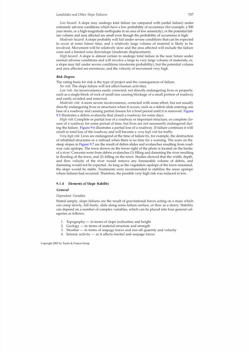
ing the failure. Figure 9.6 illustrates a partial loss of a roadway. If failure continues it willresult in total loss of the roadway and will become a very high risk for traffic.Very high risk : Lives are endangered at the time of failure by, for example, the destruction
of inhabited structures or a railroad when there is no time for a warning. The scars on thesteep slopes in Figure 9.7 are the result of debris slides and avalanches resulting from road-way cuts upslope. The town shown on the lower right of the photo is located on the banksof a river. Concerns were from debris avalanches (1) filling and damming the river resultingin flooding of the town, and (2) falling on the town. Studies showed that the width, depth,and flow velocity of the river would remove any foreseeable volume of debris, anddamming would not be expected. As long as the vegetation upslope of the town remained,the slope would be stable. Treatments were recommended to stabilize the areas upslopewhere failures had occurred. Therefore, the possible very high risk was reduced to low.
9.1.4 Elements of Slope Stability
General
Dependent VariablesStated simply, slope failures are the result of gravitational forces acting on a mass whichcan creep slowly, fall freely, slide along some failure surface, or flow as a slurry. Stabilitycan depend on a number of complex variables, which can be placed into four general cat-egories as follows:
1. Topography — in terms of slope inclination and height2. Geology — in terms of material structure and strength3. Weather — in terms of seepage forces and run-off quantity and velocity4. Seismic activity — as it affects inertial and seepage forces
Landslides and Other Slope Failures 707
opyright 2005 by Taylor & Francis Group

8/12/2019 CH. 9_Geologic Hazard; Landslides and Other Slope Failures
http://slidepdf.com/reader/full/ch-9geologic-hazard-landslides-and-other-slope-failures 12/136
It is important to note that, although topography and geology are usually constant fac-tors, there are situations where they are transient.
Mechanics of Sliding MassesMasses that fail by sliding along some well-defined surface, moving as a single unit (asopposed to progressive failure or failure by lateral spreading), are the only slope failureform that can be analyzed mathematically in the present state of the art (see Section 9.3) .
708 Geotechnical Engineering Investigation Handbook, Second Edition
FIGURE 9.5Debris avalanche closes a roadway in Ecuador for some days. A temporary bypass was constructed and useduntil the debris was removed.
opyright 2005 by Taylor & Francis Group
8/12/2019 CH. 9_Geologic Hazard; Landslides and Other Slope Failures
http://slidepdf.com/reader/full/ch-9geologic-hazard-landslides-and-other-slope-failures 13/136
The diagrams given in Figure 9.8 illustrate the concept of failure that occurs when drivingforces exceed resisting forces.
In the figure, the weight of mass W bounded by slice abc (in [a] acted on by the leverarm E; in [b] a function of the inclination of the failure surface)causing the driving force,is resisted by the shear strength s mobilized along the failure surface of length L (in case[a] acted on at “a” by lever arm R). The expression for factor of safety FS given in the fig-ure is commonly encountered but is generally considered unsatisfactory because theresisting moment and the driving moment in (a) are ambiguous. For example, the portionof the rotating mass to the left of the center of rotation could be considered as part of theresisting moment. For this reason, FS is usually defined as
FS
The four major factors influencing slope stability are illustrated in Figure 9.9 anddescribed in the following sections.
Slope Geometry (Figure 9.9a)
SignificanceDriving forces and runoff are increased as slope inclination and height increase. Runoff quan-tity and velocity are related directly to amount of erosion, and under severe conditions cause“hydraulic excavation,” resulting in avalanches and flows(see discussion of runoff below).
InclinationGeologic formations often have characteristic inclinations at which they are barely stablein the natural state, for examples, residual soils at 30 to 40°, colluvium at 10 to 20°, clayshales at 8 to 15°, and loess, which often stands vertical to substantial heights.
shearing strength available along sliding surfaceshearing stresses tending to produce failure along surface
Landslides and Other Slope Failures 709
FIGURE 9.6Partial loss of mountain roadway in Ecuador. Failure resulted from discharge from roadway drains causingdownslope erosion. Additional failure will result in total loss of roadway and closure probably for months.
opyright 2005 by Taylor & Francis Group

8/12/2019 CH. 9_Geologic Hazard; Landslides and Other Slope Failures
http://slidepdf.com/reader/full/ch-9geologic-hazard-landslides-and-other-slope-failures 14/136
710 Geotechnical Engineering Investigation Handbook, Second Edition
FIGURE 9.7Debris avalanches resulted from roadway construction on a steep slope in the Bolivian Andes. The small townof Pacallo in the photo lower right is located adjacent to a fast-flowing mountain stream. The major concernwas with future avalanches damming the stream with debris resulting in flooding of the town.
opyright 2005 by Taylor & Francis Group

8/12/2019 CH. 9_Geologic Hazard; Landslides and Other Slope Failures
http://slidepdf.com/reader/full/ch-9geologic-hazard-landslides-and-other-slope-failures 15/136
Inclination is increased by:
● Cutting during construction, which should be controlled by analysis and judgment.● Erosion, as a result of undercutting at the slope toe by wave or stream activity, of
seepage exiting from the slope face, or of removal of materials by downsloperunoff. All these are significant natural events.
●
Tectonic movements in mountainous terrain, a very subtle and long-term activ-ity which provides a possible explanation for the very large failures that occurfrom time to time and for which no other single explanation appears reasonable.An example is the disastrous rock slide at Goldau, Switzerland (see Section9.2.3).
Landslides and Other Slope Failures 711
FS*= = SLR
Failuresurface
Failuresurface
s
cb
R
E
W
Lo c
o p
a
(a) (b)
L
EWResisting momentDriving moment FS ==
Resisting force SLDriving force W sin
F =W sin
a
b c
Ls
W
FIGURE 9.8Forces acting on cylindrical and planar failure surfaces. (a) Rotational cylindrical failure surface with length L.
Safety factor against sliding, FS. (b) Simple wedge failure on planar surface with length L. (*Note that theexpression for FS is generally considered unsatisfactory; see text.)
Inclination increased by:
Cutting Height:
Increased by fillingTension cracks Cleft water pressures
Seepage forces increased by
Runoff effect icreased bby:
Runoff
Pore-water pressures
(C) increase driving forces
(P)decrease resisting forceand may increase driving forces
Joints
P
P
1. Failure surface in slides:
CC CDecreased by cutting,
erosion, or placing bermat the toe
Tectonics can increaseinclination and height
Erosion
Fg
(a)
(b) (d)
(c)
H
RR
b.a.
I
a. Rotational in homogeneousformations
1. Rainfall infiltration2. Reservoir filling3. Tides4. River floods5.Frozen grounds6. seismic forces
1. Storm intensity2. Ground saturation3. Removed vegetation4. Loose surface materials5. Slope inclination, height,
and form
2. Strength: constant or variablealong failure surface? Changedwith time by decompostion,lateral strains, solution ofcementing agents and leaching
b. Planar formations with major discontinuities
FIGURE 9.9The major factors influencing slope stability: (a) increasing slope inclination and height increases the drivingforces F; (b) geologic structure influences form and location of failure surface, material strength provides theresisting force R; (c) seepage forces reduce resisting forces along failure surface and increase driving forces in joints and tension cracks; (d) runoff quantity and velocity are major factors in erosion, avalanches, and flows.
opyright 2005 by Taylor & Francis Group

8/12/2019 CH. 9_Geologic Hazard; Landslides and Other Slope Failures
http://slidepdf.com/reader/full/ch-9geologic-hazard-landslides-and-other-slope-failures 16/136
Slope HeightSlope height is increased by filling at the top, erosion below the toe, or tectonic activity. Itis decreased by excavation and erosion at the top, or by placing a berm at the bottom. Thedriving forces are affected in failure forms where the limited slope condition applies (seeFigure 9.8).
Material Structure ( Figure 9 .9b)
SignificanceMaterial structure influences the failure form and the location and shape of the potentialfailure surface, and can be considered in two broad categories: uniform and nonuniform.
Uniform MaterialsUniform materials consist of a single type of soil or rock, essentially intact and free of dis-continuities. From the aspect of slope stability, they are restricted to certain soil formations.
Rotational failure is normal; the depth of the failure surface depends on the location of thephreatic surface and on the variation of strength with depth. Progressive failures are com-mon, and falls and flows possible; flows are common in fine-grained granular soils.
Nonuniform MaterialsFormations containing strata of various materials, and discontinuities represented by bed-ding, joints, shears, faults, foliations, and slickensides are considered nonuniform. Thecontrolling factor for stability is the orientation and strength of the discontinuities, whichrepresent surfaces of weakness in the slope.
Planar slides occur along the contacts of dipping beds of sedimentary rock and along
joints, fault and other shear zones, slickensides, and foliations. Where a relatively thindeposit of soil overlies a sloping rock surface, progressive failure is likely and maydevelop into a debris avalanche. Along relatively flat-lying strata of weak material, failurecan develop progressively in the form of lateral spreading, and can develop into a flow.
Rotational slides occur in horizontally bedded soil formations, and in certain rock forma-tions such as clay shales and horizontally bedded sedimentary rocks.
Falls occur from lack of tensile strength across joints in overhanging or vertical rockmasses. Changes in the orientation of the discontinuities with respect to the slope faceoccur normally as a result of excavation, but can also be caused by tectonic activity. Jointintensity can be affected by construction blasting.
Material Strength (Figure 9.9b)SignificanceMaterial strength provides the resisting forces along a surface of sliding. It is often neitherthe value determined by testing, nor the constant value assumed in analysis.
Variations along the Failure SurfaceSlopes normally fail at a range of strengths, varying from peak to residual, distributedalong the failure surface as a function of the strains. Slopes that have undergone failure inthe past will have strengths at or near residual, depending upon the time for restitutionavailable since failure.
Changes with TimeChemical weatheringis significant in residual soils and along discontinuities in rock massesin humid climates, and provides another possible explanation for the sudden failure of
712 Geotechnical Engineering Investigation Handbook, Second Edition
opyright 2005 by Taylor & Francis Group

8/12/2019 CH. 9_Geologic Hazard; Landslides and Other Slope Failures
http://slidepdf.com/reader/full/ch-9geologic-hazard-landslides-and-other-slope-failures 17/136
rock-mass slopes that have remained stable for a very long period of time under a varietyof weather and seismic conditions.
Lateral strains in a slope tend to reduce the peak strength toward the residual, a signifi-cant factor in the failure of slopes in clay shales and some overconsolidated clays contain-ing recoverable strain energy (Bjerrum, 1966), as well as in materials where slopemovements have occurred.
Solution of Cementing Agents Reduces Strength.Leaching of salts from marine clays increases their sensitivity and, therefore, their suscep-tibility to liquefaction and flow (Bjerrum et al., 1969).
Seepage Forces (Figure 9 .9c)
SignificanceSeepage forces may reduce the resisting forces along the failure surface or increase the
driving forces (see also Section 8.3.3) .
Factors Causing Increased Seepage ForcesIn general, seepage forces are increased by rainfall infiltration or reservoir filling, whichraises the water table or some other phreatic surface (perched water level); sudden draw-down of a flooded stream or an exceptionally high tide; melting of a frozen slope that had
blocked seepage flow; and earthquake forces.Rising groundwater level is a common cause. Variables affecting such a rise include rain-
fall accumulation and increase in ground saturation for a given period, the intensity of aparticular storm, the type and density of ground vegetation, drainage characteristics of the
geologic materials, and the slope inclination and other features of topographic expression.Vegetation, geology, and topography influence the amount of infiltration that can occur,and careful evaluation of these factors often can provide the reasons for failure to occur ata particular location along a slope rather than at some other position during a given stormor weather occurrence.
Earthquake forces(see Section 12.3.4) can cause an increase in pore-air pressures, as wellas porewater pressures. Such an increase is believed to be the cause of the devastatingextent of the massive landslides in loess during the 1920 earthquake in Kansu, China,which left 200,000 or more dead.
Runoff ( Figure 9 .9d)SignificanceThe quantity and velocity of runoff are major factors in erosion, and are a cause of avalanchesand flows. Storm intensity, ground saturation, vegetation, frozen ground, the nature of thesurficial geologic materials, and slope inclination and other topographic features affect runoff.
Hydraulic ExcavationMany avalanches and flows are caused by hydraulic excavation during intense storms, acommon event in tropical and semiarid climates. Water moving downslope picks up soilsloosened by seepage forces, and as the volume and velocity increase, the capacity toremove more soil and even boulders increases, eventually resulting in a heavy slurrywhich removes everything loose in its path as it flows violently downslope. The scar of adebris avalanche is illustrated in Figure 9.10. Failure could hardly have been foreseen atthat particular location along the slope, since conditions were relatively uniform.
Landslides and Other Slope Failures 713
opyright 2005 by Taylor & Francis Group

8/12/2019 CH. 9_Geologic Hazard; Landslides and Other Slope Failures
http://slidepdf.com/reader/full/ch-9geologic-hazard-landslides-and-other-slope-failures 18/136
9.2 Slope Failure Form Characteristics
9.2.1 Creep
General Creep is the slow, imperceptible deformation of slope materials under low stress levels,which normally affects only the shallow portion of the slope, but can be deep-seatedwhere a weak zone exists. It results from gravitational and seepage forces, and is indica-tive of conditions favorable for sliding.
Recognition Creep is characteristic of cohesive materials and soft rock masses on moderately steep tosteep slopes. Its major surface features are parallel transverse slope ridges (“cow paths”)
714 Geotechnical Engineering Investigation Handbook, Second Edition
FIGURE 9.10Exposed rock surface remaining after runoff from torrential rains removed all vegetation, soil, and loose rock,depositing the debris mass at the toe of the slope (BR 116, km 56, Teresopolis, R.J., Brazil).
opyright 2005 by Taylor & Francis Group

8/12/2019 CH. 9_Geologic Hazard; Landslides and Other Slope Failures
http://slidepdf.com/reader/full/ch-9geologic-hazard-landslides-and-other-slope-failures 19/136
as illustrated in Figure 9.11 , and tilted fence posts, poles, and tree trunks. Straight tiltedtree trunks indicate recent movement ( Figure 9.12) , whereas bent tree trunks indicate oldcontinuing movement ( Figure 9.13) (see Section 9.5.2, Dating Relict Slide Movements).
9.2.2 FallsGeneral Falls are the sudden failures of vertical or near-vertical slopes involving single or multiple
blocks wherein the material descends essentially in free fall. Toppling, or overturning of rock blocks, often results in a fall.
In soils, falls are caused by the undercutting of slopes due to stream or wave erosion,usually assisted by seepage forces. In rock masses, falls result from undercutting byerosion or human excavation; increased pressures in joints from frost, water, orexpanding materials; weathering along joints combined with seepage forces; and differ-ential weathering wherein less-resistant beds remove support from stronger beds (seeFigure 6.48) .
Their engineering significance lies normally in the occurrence of a single or a few blocksfalling on a roadway, or occasionally encountering structures on slopes. At times, how-ever, they can be massive and very destructive as shown in Figure 9.14.
Recognition Falls are characteristic of vertical to near-vertical slopes in weak to moderately strong soilsand jointed rock masses. Before total failure some displacement often occurs, as indicated
by tension cracks; after total failure, a fresh rock surface remains and talus debris accu-
mulates at the toe (see Figure 6.67 ).
Landslides and Other Slope Failures 715
FIGURE 9.11Creep ridges and erosion in residual soils after removal of vegetation (state of Rio de Janeiro, Brazil).
opyright 2005 by Taylor & Francis Group

8/12/2019 CH. 9_Geologic Hazard; Landslides and Other Slope Failures
http://slidepdf.com/reader/full/ch-9geologic-hazard-landslides-and-other-slope-failures 20/136
9.2.3 Planar Slides in Rock Masses
General Forms of planar slides in rock masses include:
● Block glide involving a single unit of relatively small size (photo, Figure 9.15 ).● Slab glide involving a single unit of relatively small to large size (photo, Figure
9.16).● Wedge failures along intersecting planes involving single to multiple units, small
to very large in size ( Figure 9.2d) . A small wedge failure is illustrated in Figure9.81.
● Translational slide: Sliding as a unit, or multiple units, downslope along oneor more planar surfaces (Figure 9.2b). Failure often is progressive ( Section 9.2.6).
● Massive rock slide involving multiple units, small to very large in size, oftenwith very high velocities ( Figure 9.17) .
Block and slab slides can be destructive, but massive rock slides are often disastrous inmountainous regions and in many cases cannot be prevented, only avoided.
716 Geotechnical Engineering Investigation Handbook, Second Edition
FIGURE 9.12Trees bent in the lower portions andthen growing straight up indicate long-term slope movements. The scarp in thephoto is the head of a progressivefailure in marine shales extendingdownslope for over a kilometer nearBandung, Java.
opyright 2005 by Taylor & Francis Group

8/12/2019 CH. 9_Geologic Hazard; Landslides and Other Slope Failures
http://slidepdf.com/reader/full/ch-9geologic-hazard-landslides-and-other-slope-failures 21/136
Landslides and Other Slope Failures 717
FIGURE 9.13Tilting tree trunks on a creeping hillsideof varved clays indicate relatively recentmovement (Tompkins Cove, New York).
FIGURE 9.14Rockfall destroyed a powerhouse (Niagara Falls, New York). Failure may actually be in the form of a hugetopple. (Photo by B. Benedict, 1956.)
opyright 2005 by Taylor & Francis Group

8/12/2019 CH. 9_Geologic Hazard; Landslides and Other Slope Failures
http://slidepdf.com/reader/full/ch-9geologic-hazard-landslides-and-other-slope-failures 22/136
718 Geotechnical Engineering Investigation Handbook, Second Edition
FIGURE 9.16Exfoliation loosening granite slabs. Impact wall on right was constructed to deflect falling and sliding blocksfrom buildings on lower slopes. Damage from falls and slab slides is a serious problem in Rio de Janeiro.
FIGURE 9.15Small granite block glide (Rio de Janeiro, Brazil).
opyright 2005 by Taylor & Francis Group

8/12/2019 CH. 9_Geologic Hazard; Landslides and Other Slope Failures
http://slidepdf.com/reader/full/ch-9geologic-hazard-landslides-and-other-slope-failures 23/136
Recognition Planar slides are characteristic of:
● Bedded formations of sedimentary rocks dipping downslope at an inclination
similar to, or less than, the slope face. They result in block glides or massive rockslides (see Examples below).● Faults, foliations, shears or joints forming long, continuous planes of weakness
that intersect the face of the slope.● Intersecting joints result in wedge failures, which can be very large in open-pit
mines.● Jointed hard rock results in block glides.● Exfoliation in granite masses results in slab glides.
Surface features:● Before total failure, tension cracks often form during slight initial displacement.●
After total failure, blocks and slabs leave fresh scarps. Massive rockslides leavea long fresh surface denuded of vegetation, varying in width from narrow towide and with a large debris mass at the toe of the slope and beyond. Since theycan achieve very high velocities, they can terminate far beyond the toe.
Examples of Major Failures
Goldau, SwitzerlandIn September 1806, a massive slab 1600 m long, 330 m wide, and 30m thick broke looseand slid downslope during a heavy rainstorm, destroying a village and killing 457 per-sons. The slab consisted of Tertiary conglomerate with a calcareous binder resting on a 30°slope. At its interface with the underlying rock was a porous layer of weathered rock.
Three possible causes were offered by Terzaghi (1950):
1. The slope inclination gradually increased from tectonic movements.2. The shearing resistance at the slab interface gradually decreased because of pro-
gressive weathering or from removal of cementing material.
Landslides and Other Slope Failures 719
FIGURE 9.17The scar of the Gros Ventre slide as seen from the Gros Ventre River, Wyoming, in August 1977.
opyright 2005 by Taylor & Francis Group

8/12/2019 CH. 9_Geologic Hazard; Landslides and Other Slope Failures
http://slidepdf.com/reader/full/ch-9geologic-hazard-landslides-and-other-slope-failures 24/136
3. The piezometric head reached an unprecedented value during the rainstorm.Terzaghi was hesitant to accept this as the only cause, since he considered itunlikely that in the entire geologic history of the region, there had not been amore severe storm. Therefore, he concluded that the slide resulted from two ormore changing conditions.
Gros Ventre, WyomingOn June 23, 1925, following heavy rains and melting snow, approximately 50 million yd 3
slid in a few minutes down the mountainside along the Gros Ventre River near GrandTeton National Park in Wyoming. The debris formed a natural dam as high as 250 ftwhich blocked the river, and resulted in a lake 3 mi long. Almost 2 years later, in May1927, water from heavy rains and melting snow filled the reservoir, over-topped the nat-ural dam, eroded a large channel, and released flood waters which resulted in a numberof deaths.
The slide scar which is still evident in 1977, 52 years later, is illustrated in Figure 9.17. Ageologic section is given in Figure 9.18. Failure occurred along clay layers in the carbona-ceous Amsden formation, dipping downslope. It appears that water entered the joints andpores of the Tensleep sandstone saturated the clay seams, and reduced or eliminated thenormal stresses.
Vaiont, ItalyOn October 9, 1963, the worst dam disaster in history occurred when more than 300 mil-lion m 3 of rock slid into the reservoir formed by the world’s highest thin-arch concretedam causing a tremendous flood which overtopped the dam and flowed into the PiaveRiver valley, taking some 2600 lives. The slide involved an area on the south side of thevalley roughly 2.3 km in width and 1.3 km in length, as shown in Figure 9.19 . The naturalslope was of the order of 20 to 30°.
A geologic section is given in Figure 9.20. The valley had formed in the trough of a syn-cline, and the beds forming the limbs dipped downslope at inclinations a few degreessteeper than the slope. The south slope consisted of Jurassic sedimentary rocks, primarilylimestones and marls occasionally interbedded with clay seams (bentonite clay at residualstrength; Patton, F. D. and Hendron, A. J., unpublished). Tectonic activity had causedregional folding, faulting, and fracturing of strata, and some of the tectonic stresses
720 Geotechnical Engineering Investigation Handbook, Second Edition
Spur ofSheep mt.
About 1½ miles
F o r m e r l a n d s u r f a c e
T e n s l e e p s s
Am s d e n f o r m a t i o n
C l a y b e d s
C a r b o n i f e r o u s
L ak e le ve lM a d i s o n l i m e s t o n e
S A
F o r m e r r i v e r
c h a n n e l
E o c e n e C r e t .J u r a s s i c T r i a s s i c C h u g w a t e r R e d b e d s E m b a r f o r m a t i o n
T e n s l e e p s a n d s t o n e
D i p 1 5 ° - 2 1 °
N
C
FIGURE 9.18Section showing geologic conditions after the Gros Ventre landslide. The landslide dammed the Gros VentreRiver. (From Alden, W.C., in Focus on Environmental Geology, Tank, R., Ed., Oxford University Press, New York(1973), 1928, pp. 146–153. With permission.)
opyright 2005 by Taylor & Francis Group

8/12/2019 CH. 9_Geologic Hazard; Landslides and Other Slope Failures
http://slidepdf.com/reader/full/ch-9geologic-hazard-landslides-and-other-slope-failures 25/136
probably remained as residual stresses in the mass. Erosion of the valley caused somestress relief of the valley walls, resulting in numerous rebound joints that produced blockymasses. In addition, groundwater had attacked the limestone, leaving cavities and con-tributing to the generally unstable conditions (Kiersch, 1965).
The slide history is given by Kiersch (1965). Large-scale slides had been common on theVaiont valley slopes, and evidence of creep had been observed near the dam as early as
1960, when the dam was completed at its final height of 267 m. During the spring andsummer of 1963, the slide area was creeping at the rate of 1 cm/week. Heavy rainsoccurred during August and September and movement accelerated to 1 cm/day. In mid-September, movement accelerated to 20 to 30 cm/day, and on the day of failure, 3 weekslater, it was 80 cm/day. Since completion of the dam, the pool had been filled graduallyand the elevation maintained at about 50 m below the crest or lower. During September,the pool rose at least 20 m higher, submerged the toe of the sliding mass, and caused thegroundwater level to rise in the sliding mass. Collapse was sudden and the entire mass toa depth of 200 m broke loose and slid to the valley floor in 30 to 60 sec, displacing thereservoir and causing a wave that rose as much as 140 m above reservoir level. The dam
itself was only slightly damaged by the wall of water but was rendered useless.Sliding was apparently occurring along the clay seams, but the actual collapse is believed to have been triggered by artesian pressures and the rising groundwater levelsthat decreased the effective weight of the sliding mass and, thereby, the resisting force atthe toe.
Landslides and Other Slope Failures 721
M o s s o l e z z o R
.
B y - p a s s t u n n e l
Casfra scin
Pineda
Explanation:
Li m it landslide, 10 - 9-63 wide cra c ks at head since 60 slide
Limit landslide 1960
Ancient land s lide, casso
Rese r voir water
Approx loc ation
Rese r voir filled by slide
Ge o .A.Kiersch 11-63
Photopoi n t, with fig.no
Drill ho l e,1961approx.to 90m
Adit,1961
Line geologic cross s e ction showing dir e ction of view
C o ntour,elev,meter s
Sinkhole,soltio n ing of limestone at de pth
Strike of b eds,with dip shown
Path,ov erflow of water,a b utments
Path o f wave in reservo i r caused by slid e
M e s a z z o R
Cass o
Erto
Cimolais 2.2km
S.Martino
T .V a i o n t
V a l d i t u a r a
Co dissagoP i a v e r i v e r
Ro ggia
CaslelloLavazzo
T.vaiont455m
525 m
Limit flood
Limit flood
Dogn a
Austria
MAP of VAIO NT RESERVOIR
Area
10-9-63
Scale
1921m
Mt. Toc
0 1km
Ba se:carta d' Italia Langaron e & cimolais,m 8 9 1031
Showing lim its landslide
Vaiont map
UdineBelluno
B r e n a t a
R .
V ic en za
Ve ro n a
P ad ua
Ve n ic e
A d r iat ic s e a
Trie s te
T a g l i a m e n t o R .
LOCALITY MAP-ITALY
P i a v e r i v e r
Limit flood
Longarone
Limit flood
P ir ago
V illa no va
A q u e d u c t
4 5 0 0 N
FIGURE 9.19Map of Vaiont Reservoir slide. (From Kiersch, G.A., in Focus on Environmental Geology, Tank, R., Ed., OxfordUniversity Press, New York (1973), Section 17, 1965, pp. 153–164. With permission.)
opyright 2005 by Taylor & Francis Group

8/12/2019 CH. 9_Geologic Hazard; Landslides and Other Slope Failures
http://slidepdf.com/reader/full/ch-9geologic-hazard-landslides-and-other-slope-failures 26/136
200
300
Scale
50 100 0 100 200 300 400 500 meters
Horizontal and vertical
400
500
600
700
800
900
1000 1100
1200
1300
1400
1500
1600
Explanation:
Slide debris, rolus
Upper crefocious thin morl&limestone, interbedded
Dogger im limestone.dense,med to thick-bedded
Sinkhole, solutioned limestone at depth
Contact,rock units dashed approx dip as platted
Principal slide plane loc approx
Foull,showing direction of movement
Lias im limestone,thin-bedde d with sandy marl interbeds
Malm fm limestone, ploty to thin-bedded,clay interbeds
Lower crefoceous limestone,thin-to med bedded
Glocial debris, morainal
B
Top of slide
Principal slide plane location approx
Groundwater level induced by reservoir (approx)
D o g g e r
M a l m f m
.
L w.c re t
Floo r gla c ial
Sh o wing loca t ion s l ide p l ane,grou nd w a ter l e vels a nd r o ck u n its
G E O LOG IC C R O S S S E C T I O N B - B ′
va ll ey
D o g g e r
L i a s f m
l i m e s t
o n u p c r e t
FIGURE 9.20Geologic section through the Vaiont Reservoir slide. (From Kiersch, G.A., Focus on Environmental Geology, Tank, R., Ed., Oxf(1973), Section 17, 1965, pp. 153–164. With permission.)
opyright 2005 by Taylor & Francis Group

8/12/2019 CH. 9_Geologic Hazard; Landslides and Other Slope Failures
http://slidepdf.com/reader/full/ch-9geologic-hazard-landslides-and-other-slope-failures 27/136
9.2.4 Rotational Slides in Rock
General In the rotational slide form, a spoon-shaped mass begins failure by rotation along a cylin-drical rupture surface; cracks appear at the head of the unstable area, and bulging appears
at the toe as the mass slumps (Figure 9.2a) . At final failure, the mass has displaced sub-stantially, and a scarp remains at the head (see Section 9.2.5 for nomenclature). The majorcauses are an increase in slope inclination, weathering, and seepage forces.
Recognition Rotational slides are essentially unknown in hard-rock formations, but are common inmarine shales and other soft rocks, and in heavily jointed stratified sedimentary rockswith weak beds.
Marine shales, with their characteristic expansive properties and highly fractured struc-ture, are very susceptible to slump failures ( Figure 6.89 ), and their wide geographic dis-tribution makes such failures common (see Section 6.7.3 ). Natural slope angles are low,about 8 to 15°, and stabilization is often difficult. Failure is often progressive and candevelop into large moving masses (see Section 9.2.6) .
Stratified sedimentary rocks can on occasion result in large slides, and in humid climatesslope failures can be common (Hamel, 1980) (see Example below).
Surface features before total failure are tension cracks; after total failure, a head scarpremains along with spoon-shaped slump topography (see Section 9.2.5).
Example of Major Failure
EventAt the Brilliant cut, Pittsburgh, Pennsylvania, on March 20, 1941, a rotational slide involv-ing 120,000 yd 3 of material displaced three sets of railroad tracks and caused a train to bederailed (Hamel, 1972). A plan of the slide area is given in Figure 9.21b.
Geological conditions are illustrated on the section given in Figure 9.21a. The basal stra-tum, Zone 1, is described as “soft clay shale and indurated clay (a massive slickensidedclaystone).” The Birmingham shale of Zone 4 is heavily jointed vertically.
Slide HistoryIn the 1930s, a large tension crack opened at the top of the slope. Sealing with concrete to
prevent infiltration was unsuccessful in stopping movement and the crack continued toopen over a period of several years. The rainfall that entered the slope through the verti-cal fractures normally drained from the slope along pervious horizontal beds. On the dayof failure, which followed a week of rainfall, the horizontal passages were blocked withice. Hamel (1972) concluded that final failure was caused by water pressure in the mass,and the failure surface was largely defined by the existing crack at the top of the slope andthe weak basal stratum.
9.2.5 Rotational Slides in Soils
General A common form of sliding in soil formations is the rotation about some axis of one or more
blocks bounded by a more or less cylindrical failure surface ( Figures 9.3a–c) . The major causesare seepage forces and increased slope inclination, and relict structures in residual soils.
Landslides and Other Slope Failures 723
opyright 2005 by Taylor & Francis Group

8/12/2019 CH. 9_Geologic Hazard; Landslides and Other Slope Failures
http://slidepdf.com/reader/full/ch-9geologic-hazard-landslides-and-other-slope-failures 28/136
Usually, neither the volume of mass involved nor the distance moved is great; therefore, theconsequences are seldom catastrophic although slump slides cause substantial damage tostructures. If their warning signs are recognized they usually can be stabilized or corrected.
Recognition
Occurrence
Slump or rotation slides are characteristic of relatively thick deposits of cohesive soilswithout a major weakness plane to cause a planar failure. The depth of the failure surfacevaries with geology.
Deep-seated failure surfaces are common in soft to firm clays and glaciolacustrine, andglaciomarine soils. Deep to shallow failure surfaces are common in residual soils, depending
724 Geotechnical Engineering Investigation Handbook, Second Edition
Birmingham sandy shale,shaly sandstonecarbonaceous silt shale
500400300
N
800
825
850875
900925 950
50 ftOpen joint filled with concrete(initial tension crack)
Bridge
Alleghenyriver Blvd.
C tracksL
Approximate limitof slide
200
(a)
(b)
800
900
E l e v a t i o n ( f t )
Slope prior to failure
Failure surface Zone 1 Zone 1
Zone 2
Zone3
Zone 4
Zone 5
Offset (ft)
Open fracture
Approximate shapeof slump
1000
Indurated clay
Clay shaleSandstone and shale
Pittsburg redbedsindurated clay
Ames limestoneDuquesne coal shale
Soil
Indurated clay and shale
FIGURE 9.21Rotational slide in rock at Brilliant Cut (Pittsburgh, Pennsylvania, March 28, 1941). (a) Generalized section
through Brilliant Cut; (b) plan of slide area. (From Hamel, J.V., Proceedings of the ASCE, 13th Symposium on Rock Mechanics, Urbana, Illinois [1971], 1972, pp. 487–572. With permission.)
opyright 2005 by Taylor & Francis Group

8/12/2019 CH. 9_Geologic Hazard; Landslides and Other Slope Failures
http://slidepdf.com/reader/full/ch-9geologic-hazard-landslides-and-other-slope-failures 29/136
on the strength increase with depth and relict rock defects. Relatively shallow failure surfacesare characteristic of colluvial soils.
Surface FeaturesDuring early failure stages tension cracks begin to form as shown in Figure 9.22 and Figure9.23. After partial failure, in a progressive mode, the slope exists as a series of small slumpsand scarps with a toe bulge as shown in Figure 9.24 , or it may rest with a single large scarpand a toe bulge as illustrated in Figure 9.25(a) . After total failure, surface features include alarge head scarp and a mass of incoherent material at the toe as shown in Figure 9.25(b)and Figure 9.93.
Slump landforms remaining after total failures provide forewarning of generally unstableslope conditions. They include spoon-shaped irregular landforms, as seen from the air(Figure 9.26 and Figure 9.27) , cylindrical scarps along terraces and water courses (seeFigure 2.17) , and hummocky and irregular surfaces, as seen from the ground (Figure 9.28and Figure 9.29) . In the stereo-pair of aerial photos shown in Figure 9.26, the slump failuremass has stabilized temporarily but probably will reactivate when higher than normal sea-sonal rainfall arrives. A small recent failure scar exists along the road in the center of theslide mass. The rounded features of the mass, resulting from weathering, and vegetationgrowth indicate that the slide is probably 10 to 15 years old, or more. In the photo, it can beseen that the steep highway cut on the opposite side of the valley appears stable, indicativeof different geologic conditions. In general, the geology consists of residual soils derivedfrom metamorphic rocks in a subtropical climate. In Figure 9.27, an old slump scar in resid-ual soils, weathering has strongly modified the features. In the photo, the tongue lobe at theintersection of the trails and the creep ridges are to be noted. The location is near the slideof Figure 9.26, as shown in Figure 2.12, a smaller-scale stereo-pair of the area.
9.2.6 Lateral Spreading and Progressive Failure
General Failure by lateral spreading is a form of planar failure which occurs in both soil and rockmasses. In general, the mass strains along a planar surface, such as shown in Figure 9.3e,represents a weak zone. Eventually, blocks progressively break free as movement retro-gresses toward the head. The major causes are seepage forces, increased slope inclinationand height, and erosion at the toe.
Failure in this mode is essentially unpredictable by mathematical analysis, since one cannotknow at what point the first tension crack will appear, forming the first block. Nevertheless,the conditions for potential instability are recognizable, since they are characteristic of certainsoil and rock formations. Failure usually develops gradually, involving large volumes, but can
be sudden and disastrous. Under certain conditions, it is unavoidable and uncontrollablefrom the practical viewpoint, and under other conditions control is difficult at best.
Recognition The failure mode is common in river valleys, particularly where erosion removes materialfrom the river banks. Characteristically, occurrence is in stiff fissured clays, in clay shales,and in horizontal or slightly dipping strata with a continuous weak zone such as those thatoccur in glaciolacustrine and glaciomarine soils. Colluvium over gently sloping residualsoils or rock also fails progressively in a form of lateral spreading.
Surface features are characterized during the early stages by tension cracks, althoughfailure can be sudden under certain conditions such as earthquake loadings. During the
Landslides and Other Slope Failures 725
opyright 2005 by Taylor & Francis Group

8/12/2019 CH. 9_Geologic Hazard; Landslides and Other Slope Failures
http://slidepdf.com/reader/full/ch-9geologic-hazard-landslides-and-other-slope-failures 30/136
726 Geotechnical Engineering Investigation Handbook, Second Edition
FIGURE 9.22(a) Small scarp along tension crack appears in photo (middle right). Small highway cut is far below to the left.
Scarp appeared after soil was removed from small slump failure at the toe (BR 101, Santa Catarina, Brazil).Movement is in residual soil. If uncorrected, a very large failure will develop. (b) Tension crack in the sameslope found in another location.
opyright 2005 by Taylor & Francis Group

8/12/2019 CH. 9_Geologic Hazard; Landslides and Other Slope Failures
http://slidepdf.com/reader/full/ch-9geologic-hazard-landslides-and-other-slope-failures 31/136
progressive failure tension cracks open and scarps form, separating large blocks. Thecracks can extend far beyond the slope face when a large mass goes into tension, evenaffecting surface structures as shown in Figure 9.30. Final failure may not develop formany years, and when it occurs it may be in a form resembling a large slump slide, or itmay develop into a flow with individual blocks floating in a highly disturbed mass,depending upon natural conditions as described in the examples below.
Failure Examples Marine Shales: GeneralClay shales, particularly those of marine origin, are susceptible to several modes of slopefailures as shown in Figure 9.31 , of which progressive failure involves the largest volumes
Landslides and Other Slope Failures 727
FIGURE 9.23Stereo-pair of aerial photos showing tension cracks of incipient slides, such as at (1), along the California coast,a short distance from Portuguese Bend.
Tension crack
Scarps
Toe bulge
Residual soil
Serial of shallowfailures
FIGURE 9.24During the intermediate stage (during partial failure),residual soils often fail progressively, forming a series of slumps in tropical climates. Blocks move downhill duringrainy periods and stabilize during dry periods.
opyright 2005 by Taylor & Francis Group

8/12/2019 CH. 9_Geologic Hazard; Landslides and Other Slope Failures
http://slidepdf.com/reader/full/ch-9geologic-hazard-landslides-and-other-slope-failures 32/136
and can be the most serious from the engineering viewpoint. Their characteristics aredescribed in Section 6.7.3, the most significant of which are their content of montmoril-lonite and their high degree of overstress. Excavation, either natural or human, results in
728 Geotechnical Engineering Investigation Handbook, Second Edition
FIGURE 9.25Slump failure occurred after cutting in fine-grained glacial till (Mountainside, New Jersey). (a) Head scarp, toe bulge, and seepage at the toe. (b) Total failure some weeks later. Slope stabilized by benching, installation of trench drain, and counterberm along the toe.
opyright 2005 by Taylor & Francis Group

8/12/2019 CH. 9_Geologic Hazard; Landslides and Other Slope Failures
http://slidepdf.com/reader/full/ch-9geologic-hazard-landslides-and-other-slope-failures 33/136
lateral strains causing the strength along certain planes to be reduced to residual values.Water entering the mass through open tension cracks and fractures assists in the develop-ment of failure conditions.
Marine Shale: Forest City LandslideThe Forest City Landslide, located on the banks of the Oahe Reservoir in South Dakota,includes an area of about 700 acres (Hunt et al., 1993). The hummocky landform, typical of marine shales and a large head scarp, is shown in the aerial oblique of Figure 9.32.
Movements toward the reservoir, of the order of several inches or more per year, were caus-ing distress in a large bridge structure. Investigations, including test borings and incli-nometer data, identified the main failure surface at depths of the order of 100 ft, extendingupslope to the head scarp, a distance of 2200 ft. The approach roadway embankment wasmoving laterally on shallower failure surfaces. A geologic section is given in Figure 9.33.
Landslides and Other Slope Failures 729
FIGURE 9.26Stereo-pair of aerial photos showing slump failure landform (scale 1:8000). (See also Figure 2.12, which shows astereo-pair of aerial photos of the general area at a scale of 1:40,000.) (From Hunt, R.E. and Santiago, W.B., proceedings of the 1st Congress Brasileiro de Geologia de Engenharia, Rio de Janeiro, August, Vol. 1, 1976, pp. 79–98.With permission.)
opyright 2005 by Taylor & Francis Group

8/12/2019 CH. 9_Geologic Hazard; Landslides and Other Slope Failures
http://slidepdf.com/reader/full/ch-9geologic-hazard-landslides-and-other-slope-failures 34/136
730 Geotechnical Engineering Investigation Handbook, Second Edition
FIGURE 9.28Slump landform in glaciolacustrine soils showing shallow slopes, creep ridges, and seepage (Barton River,Vermont). Trees in upper left are growing on slide area shown on the stereo-pair given in Figure 2.17. Slopefailures are common in this region in the spring when the ground thaws and rains arrive.
FIGURE 9.27Old slump slide in residual soils located near slide in Figure 9.26 . Photo is a portion of Figure 2.121 enlarged toshow the classical spoon shape.
opyright 2005 by Taylor & Francis Group

8/12/2019 CH. 9_Geologic Hazard; Landslides and Other Slope Failures
http://slidepdf.com/reader/full/ch-9geologic-hazard-landslides-and-other-slope-failures 35/136
Landslides and Other Slope Failures 731
FIGURE 9.29Slump-slide landform (valley of the Rio Choqueyapa, La Paz, Bolivia). High center scarp in strong sands andgravels remains after failure of underlying lacustrine soils. Slopes were extremely unstable prior tochannelization of the river, because of river erosion and flood stages. Grading of old slide in upper left is notarresting slope movements as evidenced by cracks in new highway retaining wall (not apparent in photo).Slope failures continue to occur from time to time throughout the valley (photo taken in 1973).
FIGURE 9.30One-year-old church being split into half from slope movements although located over 1 km from the slopeshown in Figure 9.29 (La Paz, Bolivia, 1972).
opyright 2005 by Taylor & Francis Group

8/12/2019 CH. 9_Geologic Hazard; Landslides and Other Slope Failures
http://slidepdf.com/reader/full/ch-9geologic-hazard-landslides-and-other-slope-failures 36/136
Aerial photos of the approach embankment are given in Figure 2.8, side-scan sonar imagesof the reservoir bottom at the slide toe are given in Figure 2.9, and a typical geologic pro-file is given in Figure 6.90.
Slope failures probably began in early postglacial times when the Missouri River incisedits channel. Modern reactivation was caused by the filling of the valley with the reservoir,and subsequent relatively rapid changes in reservoir water levels. The failing mass con-
sisted of a number of blocks, evidenced by surface tension cracks.Stabilization of the overall sliding mass was essentially achieved by excavating a largecut at the escarpment at the head and relocating the approach roadway into the cut. Theapproach embankment, failing separately, was remediated by the installation of reinforcedconcrete “dowels.”
732 Geotechnical Engineering Investigation Handbook, Second Edition
FIGURE 9.32Aerial oblique, Forest City Landslide, South Dakota. Note the head scarp and hummocky landform. (Photo byVermon Bump, SDDOT.)
Layer thickening
Shale mylonite
B
C
A
Slickensided fissures commonMore permeable zone
Weatheringzone
1A and 1B
Joints
Thin sandstone
Bentonite seam
Clay seamsTransition
11A
D?
III
FIGURE 9.31Failure forms in weathered clay shales: (A) surface slump in shallow weathered zone; (B) wedge failure along joints and sandstone seam; (C) wedge failure along thin bentonite seam may develop into large progressivefailure to (D) or beyond. (From Deere, D.U., and Patton, F.D., Proceedings of ASCE, 4th Pan American Conferenceon Soil Mechanics and Foundation Engineering, San Juan, P.R., 1971, pp. 87–170. With permission.)
opyright 2005 by Taylor & Francis Group

8/12/2019 CH. 9_Geologic Hazard; Landslides and Other Slope Failures
http://slidepdf.com/reader/full/ch-9geologic-hazard-landslides-and-other-slope-failures 37/136
Marine Shale: Panama Canal SlidesEvent: Massive slides occurred during 1907 and 1915 in the excavation for the PanamaCanal in the Culebra cut (Binger, 1948; Banks, 1972).
Geology: On the plan view of the slide areas (Figure 9.34), the irregular to gentle topog-raphy of the Cucaracha formation (Tertiary) is apparent. The Cucaracha is a montmoril-lonitic shale with minor interbedding of sandstone and siltstone more or less horizontally
bedded but occasionally dipping and emerging from natural slopes. It is heavily jointedand slickensided, and some fractures show secondary mineral fillings. Natural slopes inthe valley were relatively gentle, as shown on the geologic section given in Figure 9.35,generally about 20° or less. Laboratory consolidation tests gave values for preconsolida-tion pressure as high as 200tsf.
Slide history: Excavations of the order of 300 ft in depth were required in the Cucarachaformation. Some minor sliding occurred as the initial excavations were made on slopes of 1:1 through the upper weathered zones to depths of about 50 ft. The famous slides began
to occur when excavations reached about 100 ft. They were characterized by a bucklingand heaving of the excavation floor, at times as great as 50 ft; a lowering of the adjacentground surface upslope; and substantial slope movements. Continued excavation resultedin progressive sliding on a failure surface extending back from the cut as far as 1000 ft. Thecauses of the sliding are believed to be stress relief in the horizontal direction, followed bythe expansion of the shale, and finally rupture along a shallow arc surface (Binger, 1948).
Analysis: Banks (1972) found that at initial failure conditions, the effective strength enve-lope yielded φ 19° and c’≈ 0. For the case of an infinite slope (see Section 9.3.2) withoutslope seepage these values would produce a stable slope angle of 19°, or for the case of seepage parallel and coincident with the slope face, 1/2 φ , or 9.5°. Since movements had
occurred, the value 9.5° is considered to be the residual strength.Solution: The slides were finally arrested by massive excavation and cutting the slopes back to 9.5° (1/2 φ r), which is flatter than the natural slopes. Banks reported that measure-ments with slope inclinometers indicated that movement was still occurring in 1969, andthat the depth of sliding was at an elevation near the canal bottom.
Landslides and Other Slope Failures 733
Sta. 235
GA1900
1800
1700
1600
Bridgepier
Till
Lowerblock
Freshshale
Weathered shale
Weatheredshale
Residual soil
S c a le : 1 v :5 h
T ill
R es idu als oil
F a ilu r es u rfac e
G A'
Fill E l e v a t i o n
1500
1400
Sta. 240 Sta. 245 Sta. 250 Sta. 255 Sta. 260 Sta. 265 Sta. 270 Sta. 275
FIGURE 9.33Geologic section, Forest City Landslide, South Dakota (From Hunt, R.E. et al., 3rd International Conference, Case Histories in Geotechnical Engineering, St. Louis, 1993. With permission.)
opyright 2005 by Taylor & Francis Group

8/12/2019 CH. 9_Geologic Hazard; Landslides and Other Slope Failures
http://slidepdf.com/reader/full/ch-9geologic-hazard-landslides-and-other-slope-failures 38/136
Coastal Plain Sediments: Portuguese Bend SlideEvent: At Portuguese Bend, Palos Verdes Hills, California (see Figure 10.3 for location), aslide complex with a maximum width of roughly 4000ft and a head-to-toe length of about4600 ft began moving significantly in 1956 and as of 1984, was still moving. Coastal plainsediments are involved, primarily marine shales. This slide may be classified as progres-sive block glides or failure by lateral spreading. It is one of the most studied active slidesin the United States (Jahns and Vonder Linden, 1973).
Physiography: The limit of the slide area is shown in Figure 9.36, and the irregular hum-mocky topography is shown on the stereo-pair of aerial photos in Figure 9.37. In the slide
734 Geotechnical Engineering Investigation Handbook, Second Edition
East culebra slide
West culebra slide
Panama canallocation of major
slide areas
Old town of culebra as it existed in1909 superimposed on slide limitsand topography exisisting inMarch 1947
Scale in feet 300 0 300 600 900
Cucaracha slide
FIGURE 9.34Plan view of slides and topography, Culebra Cut, Panama Canal. (From Binger, W.V., Proceedings of the 2nd
International Conference on Soil Mechanics and Foundation Engineering, Rotterdam, Vol. 2, 1948, pp. 54–60. Withpermission.)
1400 14001200 12001000 1000800East West
Surface existing prior to american excavation
March 1947
Fault
July 1915June 1912January 1912
FeetcLStation 1782 +50
800600 600400 400
400300
C uleb r a
Culebra formation
Fault Cucaracha formation
2001000
200 200
FIGURE 9.35Sketch of east and west Culebra slides (Panama Canal) showing progress of slide movement: Cucarachatuffaceous shale and Culebra tuffaceous shale, siltstone, and sandstone. (From Binger, W.V., Proceedings of the2nd International Conference on Soil Mechanics and Foundation Engineering, Rotterdom, Vol. 2, 1948, pp. 54–60.With permission.)
opyright 2005 by Taylor & Francis Group

8/12/2019 CH. 9_Geologic Hazard; Landslides and Other Slope Failures
http://slidepdf.com/reader/full/ch-9geologic-hazard-landslides-and-other-slope-failures 39/136
area, the land rises from the sea in a series of gently rolling hills and terraces to more than600 ft above sea level. The hills beyond the slide area rise to elevations above 1200 ft andthe cliffs along the oceanfront are roughly 150 ft above the sea. A panoramic view of theslide is given in Figure 9.38.
Geology: The slide zone occurs in Miocene sediments (see Section 7.4.4) of heavily tuffa-ceous and sandy clays interbedded with relatively thin strata of bentonitic clays. Whenundisturbed, the beds dip seaward at about 10 to 20°, which more or less conforms withthe land surface as illustrated on the section ( Figure 9.39) . A badly crushed zone of indurated clayey silt forming a soil “breccia” ( Figure 9.40) is found in the lower portionsof the slide area. Present movement of the slide appears to be seated at a depth of about100 ft below the surface in the “Portuguese tuff,” originally deposited as a marine ashflow.
Landslides and Other Slope Failures 735
FIGURE 9.36Distribution of principal landslides and landslide complexes in Palos Verdes Hills, California. (From Jahns,
R.H. and Vonder Linden, C., Geology, Seismicity and Environmental Impact, Special Publication AssociationEngineering Geology, Los Angeles, 1973, pp. 123–138. With permission.)
opyright 2005 by Taylor & Francis Group

8/12/2019 CH. 9_Geologic Hazard; Landslides and Other Slope Failures
http://slidepdf.com/reader/full/ch-9geologic-hazard-landslides-and-other-slope-failures 40/136
Slide history: The area has been identified as one with ancient slide activity (see Figure9.36). Using radiometric techniques, colluvium older than 250,000 years has been dated,and intermediate activity dated at 95,000 years ago. In recent times some block movementwas noted in 1929, but during the 1950s, when housing development began on the pres-ent slide surface, the slide was considered as inactive. Significant modern movement
began in 1956, apparently triggered by loading the headward area of the slide with con-struction fill for a roadway.
Slide movements:The mass began moving initially during 1956 and 1957, at rates of 2 to 5in./year, continuing at rates varying from 6 to 24 in./year during 1958, then 3 to 10 ft/yearduring 1961 to 1968. After 1968, a significant increase in movement occurred. Eventually,120 houses were destroyed over a 300 acre area. Studies have correlated acceleration in rateof advance with earthquake activity, abnormally high tides, and rainfall (Easton, 1973). Theaverage movement in 1973 ranged from about 3 in./day during the dry season, to 4 in./day
736 Geotechnical Engineering Investigation Handbook, Second Edition
FIGURE 9.37Stereo-pair of aerial photos of the Portuguese Bend area of the Palos Verdes Hills (January 14, 1973, scale 1:24,000).
opyright 2005 by Taylor & Francis Group
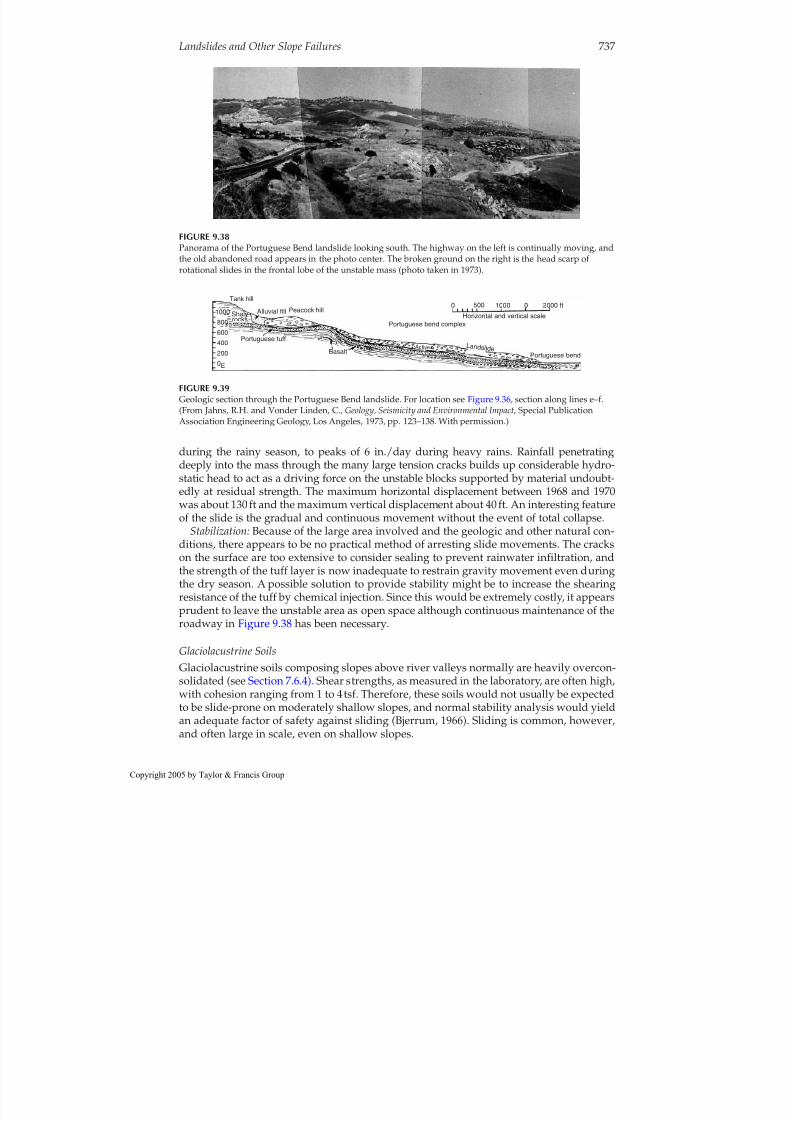
8/12/2019 CH. 9_Geologic Hazard; Landslides and Other Slope Failures
http://slidepdf.com/reader/full/ch-9geologic-hazard-landslides-and-other-slope-failures 41/136
during the rainy season, to peaks of 6 in./day during heavy rains. Rainfall penetratingdeeply into the mass through the many large tension cracks builds up considerable hydro-static head to act as a driving force on the unstable blocks supported by material undoubt-edly at residual strength. The maximum horizontal displacement between 1968 and 1970was about 130 ft and the maximum vertical displacement about 40 ft. An interesting featureof the slide is the gradual and continuous movement without the event of total collapse.
Stabilization: Because of the large area involved and the geologic and other natural con-
ditions, there appears to be no practical method of arresting slide movements. The crackson the surface are too extensive to consider sealing to prevent rainwater infiltration, andthe strength of the tuff layer is now inadequate to restrain gravity movement even duringthe dry season. A possible solution to provide stability might be to increase the shearingresistance of the tuff by chemical injection. Since this would be extremely costly, it appearsprudent to leave the unstable area as open space although continuous maintenance of theroadway in Figure 9.38 has been necessary.
Glaciolacustrine SoilsGlaciolacustrine soils composing slopes above river valleys normally are heavily overcon-
solidated (see Section 7.6.4) . Shear strengths, as measured in the laboratory, are often high,with cohesion ranging from 1 to 4 tsf. Therefore, these soils would not usually be expectedto be slide-prone on moderately shallow slopes, and normal stability analysis would yieldan adequate factor of safety against sliding (Bjerrum, 1966). Sliding is common, however,and often large in scale, even on shallow slopes.
Landslides and Other Slope Failures 737
FIGURE 9.38Panorama of the Portuguese Bend landslide looking south. The highway on the left is continually moving, andthe old abandoned road appears in the photo center. The broken ground on the right is the head scarp of
rotational slides in the frontal lobe of the unstable mass (photo taken in 1973).
0E
200400600800
Shaly
Tank hill
Portuguese tuff
Alluvial fill Peacock hill
Basalt
Portuguese bend complex
0 500 1000 0 2000 ft
Horizontal and vertical scale
Portuguese bend
F
A c t iv e L a n d s l i d e
1000rocks
FIGURE 9.39Geologic section through the Portuguese Bend landslide. For location see Figure 9.36, section along lines e–f.
(From Jahns, R.H. and Vonder Linden, C., Geology, Seismicity and Environmental Impact, Special PublicationAssociation Engineering Geology, Los Angeles, 1973, pp. 123–138. With permission.)
opyright 2005 by Taylor & Francis Group

8/12/2019 CH. 9_Geologic Hazard; Landslides and Other Slope Failures
http://slidepdf.com/reader/full/ch-9geologic-hazard-landslides-and-other-slope-failures 42/136
In the Seattle Freeway slides (Figure 9.41), failure occurred along old bedding planeshears associated with lateral expansion of the mass toward the slopes when the glacial icein the valley against the slopes disappeared (Palladino and Peck, 1972). Similar conditionsprobably existed at the site of the slide occurring at Kingston, New York, in the HudsonRiver valley in August 1915 (Terzaghi, 1950). The Kingston slide was preceded by a periodof unusually heavy rainfall. Factors contributing to failure, as postulated by Terzaghi,were the accumulation of stockpiles of crushed rock along the upper edge of the slope andperhaps the deforestation of outcrops of the aquifer underlying the varved clays whichpermitted an increase in pore-water pressures along the failure surface.
Glaciomarine Soils: South Nation River SlideEvent: The South Nation River slide in Casselman, Ontario, of May 16, 1971, is typical of many slides occurring in the sensitive Champlain clays of glaciomarine origin, in Quebec
province, Canada (Eden et al., 1971). These clays are distributed in a broad belt along theSt. Lawrence River and up the reaches of the Saguenay River. Most of the slides occuralong riverbanks, commencing as either a slump or block glide and retrogressing througheither slumping or lateral spreading. At times, the frontal lobes of the slides liquefy and
become flows (Figure 9.4f) (see Section 9.2.11 ).
738 Geotechnical Engineering Investigation Handbook, Second Edition
FIGURE 9.40Soil “breccia” of fragments of indurated clayey silt in a crushed uplifted zone at Portuguese Bend.
opyright 2005 by Taylor & Francis Group

8/12/2019 CH. 9_Geologic Hazard; Landslides and Other Slope Failures
http://slidepdf.com/reader/full/ch-9geologic-hazard-landslides-and-other-slope-failures 43/136
Geology:Glaciomarine soils in general are described in Section 7.6.5. The stratigraphy atthe South Nation River slide prior to failure consisted of 6 to 23 ft of stratified silty finesands overlying the Champlain clay (Leda clay) as shown in Figure 9.42. The undrainedstrength of the clay was about 0.5 tsf, its sensitivity ranged from 10 to 100, the averageplastic limit was 30%, and liquid limit 70%, and the natural water content was at the liq-uid limit.
Slide history: An all-time record snowfall of 170 in. (432 cm) occurred during the
1970–1971 winter and gradual melting resulted in saturation of the upper clays. The slideoccurred at the end of the snow-melting season during a heavy rainstorm. A contributingfactor was the river level at the slide toe area. It had risen as much as 30ft during springfloods, remained at that level for a week, then dropped back rapidly to preflood levels. Atthe time of the slide, groundwater at the lower part of the slope was observed to be nearlycoincident with the surface. From the appearance of the ground after failure, it appearsthat the slide retrogressed as a series of slumps as shown in Figure 9.43.
Glaciomarine Soils: Turnagain Heights SlideEvent: Much of the damage to the Anchorage, Alaska, area from the March 1964 earth-
quake was caused by landslides induced by seismic forces. The slides occurred in the cityin the Ship Creek area and along the waterfront formed by the Knik Arm of Cook Inlet.The largest slide occurred at Turnagain Heights, a bluff some 60 ft high overlooking KnikArm. Many homes were destroyed in the slide area of 125 acres as illustrated in Figure9.44. The slide at Turnagain Heights is an example of sliding along horizontal strata. It was
Landslides and Other Slope Failures 739
Original surface
Excavation
Slip plane
Glacial till
Overconsolidatedplastic clay locallyvarved, fissured
Wp=23%WL=55%W =30%
FIGURE 9.41Failure surface in overconsolidated, fissured clays, undergoing progressive failure as determined by slopeinclinometer measurements along the Seattle Freeway. (From Bjerrum, L., Terzaghi Lectures 1963–1972, ASCE[1974], 1966, pp. 139–189. With permission.)
V e r t i c a
l e
l e v a
t i o n
( f t )
Level frompiezometerin tillApril 15, 1971
Silty fine sand,loose to compact
Elevation ofgully seepage
Lc
High-water levelApril 15, 1971South nationriver
Limestone
00 100 200 300 400
ft
100
200
300
Gray sensitive silty clay (sand lenses) −soft
Silt and sand till with boulders
Mottled brownsilty clay −stiff
FIGURE 9.42Stratigraphy prior to the South NationRiver slide. An overconsolidated crustover soft, sensitive clays. (From Eden,W.J. et al., Can. Geotech. J.,8, 1971.Reprinted with permission of theNational Research Council of Canada.)
opyright 2005 by Taylor & Francis Group

8/12/2019 CH. 9_Geologic Hazard; Landslides and Other Slope Failures
http://slidepdf.com/reader/full/ch-9geologic-hazard-landslides-and-other-slope-failures 44/136
planar and evolved by block gliding or slump failure at the bluff, followed by lateralspreading of the mass for a width of 8000 ft, and extending as much as 900 ft inland.
Geology:Anchorage and the surrounding area are underlain by the Bootlegger Cove clayof glaciomarine origin. Soil stratigraphy at the bluff consisted of a thin layer of sand andgravel overlying a clay stratum over 100 ft thick as shown in Figure 9.45a . The consistencyof the upper portions of the clay was stiff to medium, becoming soft at a depth of about
50 ft. The soft zone extended to a depth of about 23 ft below sea level. Layers of silt andfine sand were present at depths of a several feet or so above sea level.Slide history:Seed and Wilson (1967) postulated that cyclic loading induced by the earth-
quake caused liquefaction of the silt and fine sand lenses resulting in instability and blockgliding along the bluff. Blocks continued to break loose and glide retrogressively, resulting
740 Geotechnical Engineering Investigation Handbook, Second Edition
FIGURE 9.43Stratigraphy after slide at South Nation River. Blocks broke loose and moved by lateral spreading. (AfterMollard, J.D., Reviews in Engineering Geology, Vol. III, Landslides, Geological Society of America, 1977, pp. 29–56.)
FIGURE 9.44Failure by block gliding and lateral spreading resulting from the 1964 earthquake, Turnagain Heights,Anchorage, Alaska. (Photo courtesy of U.S. Geological Survey, Anchorage.)
opyright 2005 by Taylor & Francis Group

8/12/2019 CH. 9_Geologic Hazard; Landslides and Other Slope Failures
http://slidepdf.com/reader/full/ch-9geologic-hazard-landslides-and-other-slope-failures 45/136
in lateral spreading of the mass which came to rest with a profile more or less as illustratedin Figure 9.45b. The movement continued for the duration of the earthquake (more than 3min), but essentially stopped once strong ground motion ceased.
Conclusions: The magnitude of the 1964 event was 8.5 (Richter) with an epicenter 80 mieast of Anchorage. Previous earthquakes of slightly lower magnitudes but closer epicen-ters had occurred, but the Turnagain Heights area had not been affected (see Section11.3.4). Seed and Wilson (1967) concluded that, in light of previous earthquake history, theslide was the result of a continuous increase in pore pressures caused by the long durationof the 1964 event; and, that it is extremely unlikely that any analysis would have antici-pated the extent of inland transgression of the failure. Considering the local stratigraphyand seismic activity, however, the area certainly should be considered as one with a highslope failure hazard.
9.2.7 Debris Slides
General Debris slides involve a mass of soil, or soil and rock fragments, moving as a unit or a num-
ber of units along a steeply dipping planar surface. They often occur progressively and candevelop into avalanches or flows. Major causes are increased seepage forces and slopeinclination, and the incidence is increased substantially by stripping vegetation. Very largemasses can be involved, with gradually developing progressive movements, but at timestotal failure of a single block can occur suddenly.
Recognition
Occurrence is common in colluvial or residual soils overlying a relatively shallow, dippingrock surface. During the initial stages of development, tension cracks are commonlyformed. After partial failure, the tension cracks widen and the complete dislodgment of one or more blocks may occur, often leaving a clean rock surface and an elliptical failurescar as shown in Figure 9.46 . Total failure can be said to have occurred when the failure
Landslides and Other Slope Failures 741
Badly disturbed samples
Badly disturbed zone7060
60
5040
40
3020
20
10 E l e v a t i o n
( f t )
E l e v a t i o n ( f t )
E l e v a t i o n
( f t )
E l e v a t i o n ( f t )
0
0
0
(b)
(a)
Shear strength (tsf) Shear strength (tsf)Shear strength (tsf)
0.50 100
−10−20
−20
Badly disturbed zone0
0 204060 feet
7060
60Silt
ClaySand and gravel
5040
40
3020
20
700
0
−10−20
−20
20 40 feet
0 0.50 100 0 00.50 100 0.50 100
FIGURE 9.45Soil profiles through east end of slide area at Turnagain Heights (a) before and (b) after failure. (From Seed,H.B. and Wilson, S.D., Proceedings of ASCE, J. Soil Mechanics Foundation Engineering Division,Vol. 93, 1967, pp.325–353. With permission.)
opyright 2005 by Taylor & Francis Group

8/12/2019 CH. 9_Geologic Hazard; Landslides and Other Slope Failures
http://slidepdf.com/reader/full/ch-9geologic-hazard-landslides-and-other-slope-failures 46/136
surface reaches to the crest of the hill. If uncorrected, failure often progresses upslope as blocks break loose.
Examples of Major Failures Pipe Organ SlideDescription: The Pipe Organ slide in Montana (Noble, 1973) triggered by a railroad cutmade at the toe, involved about 9 million yd 3 of earth. The failure surface developed atdepths below the surface of 120 to 160 ft in a Tertiary colluvium of stiff clay containingrock fragments, which overlay a porous limestone formation.
Slide movements:During sliding, movement continued for a year at an average rate of 2in./week, developing in a progressive mode. Total movement was about 12 ft and thelength of the sliding mass was 2000 ft along the flatter portions of a mountain slope.
Stabilization: Movement was arrested by the installation of pumped wells, which weredrilled into the porous limestone and later converted into gravity drains. The waterperched on the sliding surface near the interface between the colluvium and the limestonedrained readily into the limestone and the hydrostatic pressures were relieved.
Golden SlideDescription: A railroad cut into colluvium of about 50 ft thick caused a large slide nearGolden, Colorado (Noble, 1973). The colluvium is an overconsolidated clay with frag-ments of clay shale and basalt overlying a very hard blue-gray clayey siltstone. The watertable was midway between the ground surface and the failure surface, and there was evi-dence of artesian pressure at the head of the slide.
Slide movements: Movement apparently began with a heavy rainfall and was about 1in./day. Tension cracks developed in the surface and progressed upslope with time. About500,000 yd3 of material were moving within a length of about 1000ft.
Stabilization: Cutting material from the head of the slide and placing approximately100,000 yd3 against a retaining wall at the toe that penetrated into underlying sound rock
742 Geotechnical Engineering Investigation Handbook, Second Edition
FIGURE 9.46Small debris-slide scar along the Rio Santos Highway, Brazil. Note seepage along the rock surface, the slidingplane. Failure involved colluvium and the part of the underlying rock. The area subsequently was stabilized bya concrete wall.
opyright 2005 by Taylor & Francis Group

8/12/2019 CH. 9_Geologic Hazard; Landslides and Other Slope Failures
http://slidepdf.com/reader/full/ch-9geologic-hazard-landslides-and-other-slope-failures 47/136
was unsuccessful. Movement was finally arrested by the installation of horizontal drainsas long as 400 ft, and vertical wells which were being pumped daily at the time that Noble(1973) prepared his paper.
Colluvium on Shale Slopes
The Pennington shale of the Cumberland plateau in Tennessee and the sedimentary stratain the Appalachian plateau of western Pennsylvania develop thick colluvial overburden,which is the source of many slide problems in cuts and side-hill fills. The geology, nature of slope problems, and solutions are described in detail by Royster (1973, 1979) and Hamel(1980).
9.2.8 Debris Avalanches
General
Debris avalanches are very rapid movements of soil and rock debris which may, or maynot, begin with rupture along a failure surface. All vegetation and loose soil and rockmaterial may be scoured from a rock surface as shown in Figure 9.7. Major causes are highseepage forces, heavy rains, snowmelts, snowslides, earthquakes, and the creep and grad-ual yielding of rock strata.
Failure is sudden and without warning, and essentially unpredictable except for therecognition that the hazard exists. Effects can be disastrous in built-up areas at the toes of high steep slopes under suitable geologic conditions (see Examples below).
Occurence
Debris avalanches are characteristic of mountainous terrain with steep slopes of residualsoils where topography causes runoff concentration (see Figure 9.86) , or badly fracturedrock such as illustrated in Figure 9.47.
There is usually no initial stage, although occasionally tension cracks may be apparentunder some conditions. Total failure occurs suddenly either by a rock mass breaking looseor by “hydraulic excavation” which erodes deep gullies in soil slopes during torrentialrains as shown in Figure 9.48. All debris may be scoured from the rock surface anddeposited as a terminal lobe at a substantial distance from the slope. As shown in Figure9.49, the force is adequate to move large boulders, and erosion can cause the failure areato progress laterally to affect substantial areas.
In the Andes Mountains of South America, debris avalanches are the most commonform of slope failures. They occur occasionally in natural slopes, not impacted on by con-struction, but normally are caused by roadway cuts. Typical geologic conditions areshown in Figure 9.50. Illustrated in Figure 9.51 are the steep slopes and irregular topogra-phy that result in the necessity for numerous cuts for roadway construction. The slopeshown in the photo, Figure 9.52, taken in 2002, was free of slope failures in 1995.Investigation and treatments of slopes in the Andes is discussed in Section 9.5.
Examples of Major Failures
Rio de Janeiro, BrazilEvent: A debris avalanche occurred during torrential rains in 1967 in the Laranjeiras sec-tion of Rio de Janeiro, which destroyed houses and two apartment buildings, causing thedeath of more than 130 persons. The avalanche scar and a new retaining wall are shownin Figure 9.53.
Landslides and Other Slope Failures 743
opyright 2005 by Taylor & Francis Group

8/12/2019 CH. 9_Geologic Hazard; Landslides and Other Slope Failures
http://slidepdf.com/reader/full/ch-9geologic-hazard-landslides-and-other-slope-failures 48/136

8/12/2019 CH. 9_Geologic Hazard; Landslides and Other Slope Failures
http://slidepdf.com/reader/full/ch-9geologic-hazard-landslides-and-other-slope-failures 49/136
Landslides and Other Slope Failures 745
FIGURE 9.48The force of hydraulic excavation is evident in this photo taken in a typical V-shaped scarred zone of a debrisavalanche. Location is near the crest of the hill in Figure 9.49. The bedrock surface is exposed.
FIGURE 9.49Debris avalanche that covered BR 101 near Tubarao, Santa Catalina, Brazil during torrential rains in 1974. Notethe minibus for scale. The debris lobe crossed the highway and continued for a distance of about 200 m andcarried boulders several meters in diameter. Debris has been removed from the roadway. It is unlikely that afailure of such a magnitude could have been foreseen for this particular location.
opyright 2005 by Taylor & Francis Group

8/12/2019 CH. 9_Geologic Hazard; Landslides and Other Slope Failures
http://slidepdf.com/reader/full/ch-9geologic-hazard-landslides-and-other-slope-failures 50/136
Ranrahirca and Yungay, PeruEvent no. 1: One of the most disastrous debris avalanches in modern history occurred inthe Andes Mountains of Peru on January 10, 1962. In a period of 7min, 3500 lives were lostand seven towns, including Ranrahirca, were buried under a mass of ice, water, and debris(McDonald and Fletcher, 1962). The avalanche began with the collapse of Glacier 512 from
746 Geotechnical Engineering Investigation Handbook, Second Edition
R e s i d u
a l o r
c o l l u v
i a l s o
i l
Highway cut
H i g h l y f r a c
t u r e d
r o c k
S e e p a g e
M o d e
r a t e l y t o l i g h t l y f r
a c t u r e
d r o c k
FIGURE 9.50Typical geologic conditions in the AndesMountains. Slopes often inclined at 35 to40°.
To La Paz>
New Road
K i l o m e t e r s / 1 0 0
K i l o m e t e r s /
1 0 0
RioHuarinillo
km 36
Coroico
Old RoadFacailo
Cotapata Km 0
3000
M e t e r s
2 0 0 0
4 0 0
6 0 0
8 0 0
1 0 0 0
1 2 0 0
1 4 0 0
2000
1000
1 4 0 0
1 2 0 0
1 0 0 0
8 0 0 6 0
0 4 0
0 2 0
0 0
FIGURE 9.51Three-dimensional diagram of a new roadway in the Andes of Bolivia. Steep slopes and irregular landformresults in numerous cuts. See Figure 9.7 for debris avalanches above town of Pacallo, and at km 36, Figure 9.52.
opyright 2005 by Taylor & Francis Group

8/12/2019 CH. 9_Geologic Hazard; Landslides and Other Slope Failures
http://slidepdf.com/reader/full/ch-9geologic-hazard-landslides-and-other-slope-failures 51/136
Landslides and Other Slope Failures 747
FIGURE 9.52Debris avalanches at km 36 along the roadway shown in Figure 9.51. There were no slope failures at the beginning of construction in 1995. The photo, taken by the author, shows conditions during 2002, after severalyears of El Nino. At this time construction was not complete.
FIGURE 9.53Scar of debris avalanche of February 18, 1967, which destroyed two apartment buildings and took 132 lives inthe Larenjeiras section of Rio de Janeiro. The buttressed wall was constructed afterward. Debris avalanchesneed not be large to be destructive.
opyright 2005 by Taylor & Francis Group

8/12/2019 CH. 9_Geologic Hazard; Landslides and Other Slope Failures
http://slidepdf.com/reader/full/ch-9geologic-hazard-landslides-and-other-slope-failures 52/136
the 7300-m-high peak, Nevada Huascaran. Triggered by a thaw, 3 million tons of ice felland flowed down a narrow canyon picking up debris and spilling out onto the fertile val-ley at an elevation 4000 m lower than the glacier and a distance of 15 km. The debrisremaining in the towns ranged from 10 to 20m thick.
Event No. 2: The catastrophe was almost duplicated on May 32, 1970, when the bigPeruvian earthquake caused another avalanche from Nevada Huascaran that buriedYungay, adjacent to Ranrahirca, as well as Ranrahirca again, taking at least 18,000 lives(Youd, 1978). During the 1962 event, Yungay had been spared. The average velocity of theavalanche has been given as 320km/h (200 mi/h) (Varnes, 1978), and the debris flowedupstream along the Rio Santa for a distance of approximately 2.5 km. As with the 1962 fail-ure, the avalanche originated when a portion of a glacier on the mountain peak brokeloose.
9.2.9 Debris Flows
General Debris flows are similar to debris avalanches, except that the quantity of water in thedebris-flow mass causes it to flow as a slurry; in fact, differentiation between the twoforms can be difficult. The major causes are very heavy rains, high runoff, and loose sur-face materials.
Recognition Occurrence is similar to debris avalanches, but debris flows are more common in steepgullies in arid climates during cloudbursts, and the failing mass can move far from itssource (see Figure 9.4c) .
9.2.10 Rock-Fragment Flows
General A rock mass can suddenly break loose and move downslope at high velocities as a resultof the sudden failure of a weak bed or zone on the lower slopes causing loss of support tothe upper mass. Weakening can be from weathering, frost wedging, or excavation. Failureis sudden, unpredictable, and can be disastrous.
Recognition High, steep slopes in jointed rock masses offer the most susceptible conditions. The ava-lanche illustrated in Figure 9.47 could also be classified as a dry rock flow because of itsvelocity and lack of water. In the initial stages tension cracks may develop; after the finalstage a scarred surface remains over a large area, and a mass of failed debris may extendfar from the toe of the slope.
Example of Major Failure
EventThe Turtle Mountain slide of the spring of 1903 destroyed part of the town of Frank,Alberta, Canada. More than 30 million m 3 of rock debris moved downslope and out ontothe valley floor for a distance of over 1 km in less than 2 min.
748 Geotechnical Engineering Investigation Handbook, Second Edition
opyright 2005 by Taylor & Francis Group
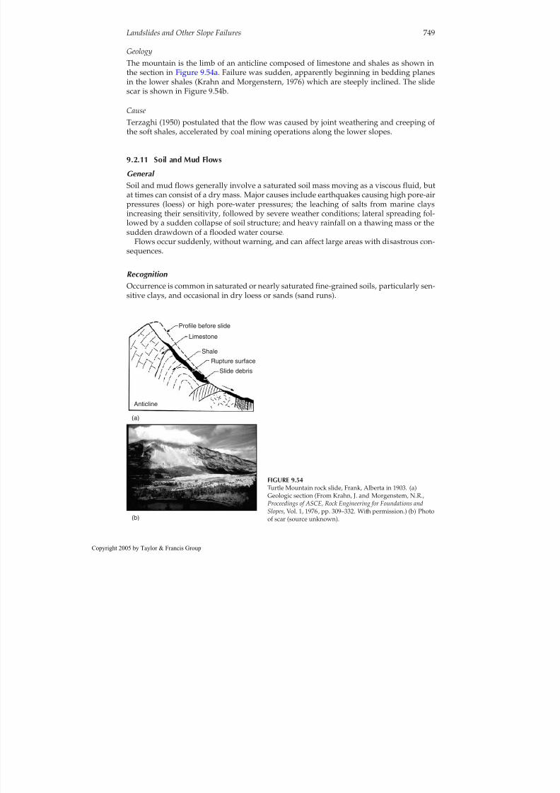
8/12/2019 CH. 9_Geologic Hazard; Landslides and Other Slope Failures
http://slidepdf.com/reader/full/ch-9geologic-hazard-landslides-and-other-slope-failures 53/136
GeologyThe mountain is the limb of an anticline composed of limestone and shales as shown inthe section in Figure 9.54a. Failure was sudden, apparently beginning in bedding planesin the lower shales (Krahn and Morgenstern, 1976) which are steeply inclined. The slidescar is shown in Figure 9.54b.
CauseTerzaghi (1950) postulated that the flow was caused by joint weathering and creeping of the soft shales, accelerated by coal mining operations along the lower slopes.
9.2.11 Soil and Mud Flows
General Soil and mud flows generally involve a saturated soil mass moving as a viscous fluid, butat times can consist of a dry mass. Major causes include earthquakes causing high pore-airpressures (loess) or high pore-water pressures; the leaching of salts from marine claysincreasing their sensitivity, followed by severe weather conditions; lateral spreading fol-lowed by a sudden collapse of soil structure; and heavy rainfall on a thawing mass or thesudden drawdown of a flooded water course.
Flows occur suddenly, without warning, and can affect large areas with disastrous con-sequences.
Recognition Occurrence is common in saturated or nearly saturated fine-grained soils, particularly sen-sitive clays, and occasional in dry loess or sands (sand runs).
Landslides and Other Slope Failures 749
Profile before slide
Limestone
ShaleRupture surface
Slide debris
Anticline
(a)
(b)
FIGURE 9.54Turtle Mountain rock slide, Frank, Alberta in 1903. (a)Geologic section (From Krahn, J. and Morgenstern, N.R.,Proceedings of ASCE, Rock Engineering for Foundations andSlopes, Vol. 1, 1976, pp. 309–332. With permission.) (b) Photoof scar (source unknown).
opyright 2005 by Taylor & Francis Group

8/12/2019 CH. 9_Geologic Hazard; Landslides and Other Slope Failures
http://slidepdf.com/reader/full/ch-9geologic-hazard-landslides-and-other-slope-failures 54/136
During initial stages flows may begin by slump failure followed by lateral spreading inthe case of sensitive clays. During final failure, a tongue-shaped lobe of low profile extends
back to a bottleneck-shaped source area with a small opening at the toe of the flow asshown in Figure 9.4f, and a distinct scarp remains at the head. Flowing masses can extendfor great distances, at times measured in kilometers.
Examples of Major Failures
Achocallo Mudflow, La Paz, BoliviaBelieved triggered by an earthquake some thousands of years ago, an enormous portionof the rim of the Bolivian altiplano (elevation 4000 m), roughly 9 km across, slipped looseand flowed down the valley of the Rio Achocallo into the Rio La Paz at an elevationapproximately 1500 m lower. The flow remnants extend downstream today for a distanceof about 25 km, part of which are shown on the aerial oblique panorama given in Figure9.55. The head scarp is shown on the photo (Figure 9.56).
The altiplano is the remains of an ancient lake bed, probably an extension of LakeTiticaca, underlain by a thick stratum of sand and gravel beneath which are at least sev-eral hundred meters of lacustrine clays and silts, interbedded with clays of volcanic ori-gin. The photo (see Figure 10.36) of a large piping tunnel was taken in the bowl-shapedvalley about 3 km downslope from the rim.
Province of Quebec, CanadaEvent: In Saint Jean Vianney, on May 4, 1971, a mass of glaciomarine clays completely liq-uefied, destroying numerous homes and taking 31 lives (Tavenas et al., 1971).
Description: The flow began in the crater of a much larger 500-year-old failure (deter-
mined by carbon-14 dating). Soil stratigraphy consisted of about 100ft of disturbed clayswith sand pockets from the ancient slide debris, overlying a deep layer of undisturbedglaciomarine clay. Occurring just after the first heavy rains following the spring thaw, theflow apparently began as a series of slumps from the bank of a small creek, which formeda temporary dam. Pressure built up behind the dam, causing it to fail, and 9 million yd 3 of completely liquefied soils flowed downstream with a wavefront 60 ft in height and avelocity estimated at 16 m/h. The flow finally discharged into the valley of the SaguenayRiver, 2 mi from its source.
Causes: Slope failures in the marine clays of Quebec are concentrated in areas that seemto be associated with a groundwater flow regime resulting from the existence of valleys inthe underlying rock surface (Tavenas et al., 1971). The valleys cause an upward flow gra-dient and an artesian pressure at the slope toes. The upper part of the soil profile is sub-
jected to a downward percolation of surface water because of the existence of sand strata.The downward percolation and upward flow produce an intense leaching of the clay,resulting in a decrease of the undrained shear strength and an increase in sensitivity (seeSection 7.6.5 ). The evidence tends to indicate that the leaching is a function of the gradi-ent. Field studies have shown a close relationship between the configuration of the
bedrock and the properties of the underlying clay deposit.
Norwegian “Quick” ClaysRegional geology:Approximately 40,000 km 2 of Norway has deposits of glaciomarine clayswhich overlie an irregular surface of granite gneiss, similar to conditions in Quebec.During postglacial times, the area has been uplifted to place the present surface about180 m above sea level. Typical stratigraphy includes 5 to 7 m of a stiff, fissured clay over-lying normally consolidated soft marine clay which extends to depths greater than 70m in
750 Geotechnical Engineering Investigation Handbook, Second Edition
opyright 2005 by Taylor & Francis Group

8/12/2019 CH. 9_Geologic Hazard; Landslides and Other Slope Failures
http://slidepdf.com/reader/full/ch-9geologic-hazard-landslides-and-other-slope-failures 55/136

8/12/2019 CH. 9_Geologic Hazard; Landslides and Other Slope Failures
http://slidepdf.com/reader/full/ch-9geologic-hazard-landslides-and-other-slope-failures 56/136
some locations (see Section 7.6.5) . Rock varies from outcropping at the surface in stream
valleys to over 70 m in depth. The quick clays are formed by leaching of salts, but theleaching is believed to be caused by artesian pressure in the rock fractures from below,rather than downward percolation of water (Bjerrum et al., 1969). Sensitivity values aredirectly related to the amount of leaching and the salt content, and are greatest where rockis relatively shallow, about 15 to 35 m.
Slope failures are common events. The natural slopes are stable at about 20° where thereis a stiff clay crust. Seepage parallel to the slopes occurs in fissures in the clay, and the stiff clay acts as a cohesionless material with slopes at i 1/2 φ ’, and φ 38° (see the infiniteslope problem in Section 9.3.2) . Stream erosion causes small slides in the weathered stiff clay; the sliding mass moves into the soft clay, which upon deformation becomes quick
and flows. In one case cited by Bjerrum et al. (1969), 200,000 m3
flowed away from thesource in a few minutes.Solution: Since stream degrading appears to be a major cause of the flows, Bjerrum et al.
(1969) proposed the construction of small weirs to impede erosion in streams where fail-ures pose hazards.
752 Geotechnical Engineering Investigation Handbook, Second Edition
FIGURE 9.56The head scarp of the Achocallo mud flow, near La Paz, Bolivia (see Figure 9.55) .
opyright 2005 by Taylor & Francis Group

8/12/2019 CH. 9_Geologic Hazard; Landslides and Other Slope Failures
http://slidepdf.com/reader/full/ch-9geologic-hazard-landslides-and-other-slope-failures 57/136
9.2.12 Seafloor Instability
General Various forms of slope failures have been recognized offshore, including deep rotationalslides (Figure 9.57) and shallow slumps, flows, and collapsed depressions (Figure 9.58).
Major causes are earthquakes, storm waves inducing bottom pressures, depositional loadsaccumulating rapidly and differentially over weak sediments, and biochemical degrada-tion of organic materials forming large quantities of gases in situ which weaken theseafloor soils.
Offshore failures can occur suddenly and unpredictably, destroying oil production plat-forms, undersea cables, and pipelines. Large flows, termed “turbidity currents,” can movetremendous distances.
Recognition Occurrence is most common in areas subjected to earthquakes of significant magnitudeand on gently sloping seafloors with loose or weak sediments, especially in rapidly accret-ing deltaic zones.
After failure the seafloor is distorted and scarred with cracks, scarps, and flow lobessimilar to those features which appear on land as illustrated in Figure 9.58. Active areasare explored with side-scan sonar (Figure 9.59) and high-resolution geophysical surveys(see Figure 9.57).
Examples of Major Failures
Gulf of Alaska
The major slide illustrated on the high-resolution seismic profile given in Figure 9.57apparently occurred during an earthquake, and covers an area about 15 km in length.Movement occurred on a 1° slope and is considered to be extremely young (Molnia et al.,1977). As shown in the figure, the slide has a well-defined head scarp, disrupted bedding,and a hummocky surface.
Gulf of MexicoMovements are continually occurring offshore of the Mississippi River delta. During hur-ricane Camille in August 1969, wave-induced bottom pressures caused massive seafloormovements that destroyed two offshore platforms and caused a third to be displaced over
a meter on a bottom slope that was very flat, less than 0.5% (Focht and Kraft, 1977).
Landslides and Other Slope Failures 753
0South 1 3 3 5
1 3 4 0
1 3 4 5
2 2 5 m
1 3 5 0
1 3 5 5
1 4 0 0
1 9 5 m
1 4 0 5
1 4 1 0
1 4 1 5
1 3 5 m
1 4 2 0
1 4 2 5
1 4 3 0
9 3 m
1 4 3 5 6 9 m
1 4 4 0
1 4 4 5
4 1 m
1 4 5 0
North0
100
200
300
0.25
T w o - w a y
t r a v e l t i m e
( s e c )
W a t e r
d e p t h ( m )
0.5
0 5 kmFIGURE 9.57High-resolution seismic reflection profile showing a portion of the Kayak Trough slump slide in the Gulf of Alaska. (From Molnia, B.F. et al., in Reviews in Engineering Geology, Vol. VIII, Landslides, Coates, D.R., Ed.,Geologic Society of America, 1977, pp. 137–148. With permission.)
opyright 2005 by Taylor & Francis Group

8/12/2019 CH. 9_Geologic Hazard; Landslides and Other Slope Failures
http://slidepdf.com/reader/full/ch-9geologic-hazard-landslides-and-other-slope-failures 58/136
754 Geotechnical Engineering Investigation Handbook, Second Edition
Elongateretrogessive
slide
Prodelta clays
Collapse depression
Undisturbed seafloor
Overlapping toe lobesBottleneck slide
Interdistributarybay
Continental slopemud diapir
C o n t i n e
n t a l s l o p
e
300 m ~
Growth faultsIncipient mud diapir
Bar front slumps(peripheral slumps)
Large arcuate shelfedge fault system
Deep normal fault
Shelf edge slumpMud/gas vents
Undisturbed seafloor
Pressure ridgesCoalescingmudflow noses
Mudflowguly
River mouthMud diapir
Pleistocene silts and clays
Undulatingmudflow floor
Remolded sediment
FIGURE 9.58Schematic block diagram illustrating the various forms of slope failure in the offshore Mississippi River delta.(From Coleman, J. M. et al., Open File Report No. 80.01,Bureau of Land Management, U.S. Department of Interior, 1980. With permission.)
FIGURE 9.59Side-scan sonar mosaic illustratingseafloor mudflows (offshore Gulf of Mexico). Grids are 25 m (82 ft) apart andthe mosaic covers an area approximately1.5 km in length. (Mosaic courtesy of Dr. J. M. Coleman, Coastal Studies Institute,Louisiana State University.)
opyright 2005 by Taylor & Francis Group

8/12/2019 CH. 9_Geologic Hazard; Landslides and Other Slope Failures
http://slidepdf.com/reader/full/ch-9geologic-hazard-landslides-and-other-slope-failures 59/136

8/12/2019 CH. 9_Geologic Hazard; Landslides and Other Slope Failures
http://slidepdf.com/reader/full/ch-9geologic-hazard-landslides-and-other-slope-failures 60/136
shear strength along the failure surface, and the magnitude of the driving forces. Staticallydeterminate failure forms may be classified as:
● Infinite slope — translation on a plane parallel to the ground surface whoselength is large compared with its depth below the surface (end effects can be neg-lected) (Figure 9.63) (Morgenstern and Sangrey, 1978).
● Finite slope, planar surface — displacement of one or more blocks, or wedge-shaped bodies, along planar surfaces with finite lengths (Figure 9.66).
● Finite slope, curved surface — rotation along a curved surface approximated bya circular arc, log-spiral, or other definable cylindrical shape ( Figure 9.76) .
Failure origin: As stresses are usually highest at the toe of the slope, failure often beginsthere and progresses upslope, as illustrated in Figure 9.60, which shows the distributionof active and passive stresses in a slope where failure is just beginning. Failures can beginat any point along a failure surface, however, where the stresses exceed the peak strength.
Because failure often is progressive, it usually occurs at some average shear strength thatcan be considerably less than the peak strength measured by testing techniques.
Limit Equilibrium AnalysisMost analytical methods applied to evaluate slope stability are based on limiting equilib-rium, i.e., on equating the driving or shearing forces due to water and gravity to the resist-ing forces due to cohesion and friction.
Shearing forces result from gravity forces and internal pressures acting on a mass bounded by a failure surface. Gravity forces are a function of the weight of the materials,slope angle, depth to the failure surface, and in some cases, slope height. Pressures
develop in joints in rock masses from water, freezing, swelling materials, or hydration of minerals and, in soils, from water in tension cracks and pores.Resisting forces, provided by the shear strength along the failure surface, are decreased
by an increase in pore pressures along the failure surface, by lateral strains in overconsol-idated clays in clay shales, by dissolution of cementing agents and leaching, or by thedevelopment of tension cracks (which serve to reduce the length of the resisting surface).
Safety factor against rupture, given as
FS (9.1)shearing strength available along the sliding surface
shearing stresses tending to produce failure along the surface
756 Geotechnical Engineering Investigation Handbook, Second Edition
45 + /2
−
i >45 + /2
B
A
Bxx
++ Failure
surface
x
(b)
x
(a)
z1
z0z0
Expansion
Activezone
Activezone
Passivezone
i
A
Compression
Passivezone
FIGURE 9.60Active and passive stresses acting on a slope. The passive resistance at the lower portions is most significant.(a) Distribution of stresses on slope with i > φ (failure beginning). (b) A case of rupture where indicates zonesof passive stress and indicates zones of active stress, subjected to tension cracks.
opyright 2005 by Taylor & Francis Group

8/12/2019 CH. 9_Geologic Hazard; Landslides and Other Slope Failures
http://slidepdf.com/reader/full/ch-9geologic-hazard-landslides-and-other-slope-failures 61/136
Shear Strength Factors (see also Section 3 .4)
Strength ParametersThe basic strength parameters are the angle of internal friction φ and cohesion c. Frictionalresistance based on φ is a function of the normal stress, and the maximum frictional shear
strength is expressed as
Smax N tan φ (9.2)
Cohesion c is independent of the normal stress and acts over the area of the failure sur-face.
Total and Effective StressesIn the total stress condition, the measured stress includes both pore-water pressures andstresses from grain-to-grain contact. In the effective stress condition, stresses from grain-to-grain contact are measured, which increase as pore pressures dissipate. Effective stressequals total stress minus pore pressure.
Pore-water pressures ( U for total, u for unit pressures) are induced either by a loadapplied to a saturated specimen, or by the existence of a phreatic surface above the slidingsurface. They directly reduce the normal force component N , and shearing resistance isthen expressed as
Smax (N U )tan φ (9.3)
In Figure 9.66, therefore, if pore pressures become equal to the normal component of theweight of the block, there will be no shearing resistance.
Failure CriteriaThe Mohr–Coulomb criterion defines failure in terms of unit shear strength and totalstresses as
s c σ ntan φ (9.4)
The Coulomb–Terzaghi criterion accounts for pore-water pressures by defining failure in
terms of effective stresses as
s c’ σ n’tanφ ’ (9.5)
where c’ is the effective cohesion; σ n’ the effective normal stress ( p – u) with p total nor-mal stress. In a slope, the total pressure p per unit of area at a point on the sliding surfaceequals h z γ t/cos 2 θ , where hz is the vertical distance from the point on surface of sliding totop of slope, γ t the slope unit weight of soil plus water, and θ the inclination of surface of sliding at point with respect to horizontal; u the pore-water pressure, in a slope u hwγ w,the piezometric head times the unit weight of water; and φ ’ the effective friction angle.
The strength parameters representing shearing resistance in the field are a function of the material type, slope history, drainage conditions, and time. Most soils (except purelygranular materials and some normally consolidated clays) are represented by both param-eters φ and c, but whether both will act during failure depends primarily on drainage con-ditions; and, the stress history of the slope.
Landslides and Other Slope Failures 757
opyright 2005 by Taylor & Francis Group

8/12/2019 CH. 9_Geologic Hazard; Landslides and Other Slope Failures
http://slidepdf.com/reader/full/ch-9geologic-hazard-landslides-and-other-slope-failures 62/136
Undrained vs. Drained StrengthUndrained conditions exist when a fully saturated slope is sheared to failure so rapidlythat no drainage can occur, as when an embankment is placed rapidly over soft soils. Suchconditions are rare except in relatively impervious soils such as clays. Soil behavior maythen be regarded as purely cohesive (see Figure 3.29) and φ 0. Results are interpreted interms of total stresses, and su, the undrained strength, applies. The case of sudden draw-down of an adjacent water body is an undrained condition, but analysis is based on theconsolidated undrained (CU) strength of the soil before the drawdown. This strength isusually expressed in terms of the CU friction angle.
Drained or long-term conditions exist in most natural slopes, or some time after a cut ismade and drainage permitted. Analysis is based on effective stresses, and the parametersφ ’ and c’ will be applicable.
Peak and Residual StrengthThe foregoing discussion, in general, pertains to peak strengths. When materials continueto strain beyond their peak strengths, however, resistance decreases until a minimumstrength, referred to as the ultimate or residual strength, is attained. The residual strength,or some value between residual and peak strengths, normally applies to a portion of thefailure surface for most soils; therefore, the peak strength is seldom developed over theentire failure surface.
Progressive failure, when anticipated, has been approximately evaluated by using the resid-ual strength along the upper portion of the failure surface, and the peak strength at maximumnormal stress along the lower zone (Conlon as reported in Peck, 1967; Barton, 1972).
Stiff fissured claysand clay shalesseldom fail in natural slopes at peak strength, but ratherat some intermediate level between peak and residual. Strength is controlled by their sec-
ondary structure. The magnitude of peak strength varies with the magnitude of normalstress, and the strain at which peak stress occurs also depends on the normal stress (Peck,1967). Because the normal stress varies along a failure surface in the field, the peakstrength cannot be mobilized simultaneously everywhere along the failure surface.
Residual strength applies in the field to the entire failure surface where movement hasoccurred or is occurring. Deere and Patton (1971) suggest using φ r (the residual frictionangle), where preexisting failure surfaces are present.
Other Strength FactorsStress levels affect strength. Creep deformation occurs at stress levels somewhat lower
than those required to produce failure by sudden rupture. A steady, constant force maycause plastic deformation of a stratum that can result in intense folding, as illustrated inFigure 9.61. Shear failure by rupture occurs at higher strain rates and stress levels and dis-tinct failure surfaces are developed as shown in Figure 9.62. The materials are geneticallythe same, i.e., varved clays from the same general area.
The strength of partially saturated materials (see Section 3.4.2) cannot be directly evalu-ated by effective stress analysis since both pore-air and pore-water pressures prevail.Residual soils, for example, are often partially saturated when sampled. In Brazil, effectivestress analysis has sometimes been based on parameters measured from direct shear testsperformed on saturated specimens to approximate the most unfavorable field conditions(Vargas and Pichler, 1957). Depending upon the degree of field saturation, the saturatedstrengths may be as little as 50% of the strength at field moisture. Apparent cohesionresults from capillary forces in partially saturated fine-grained soils such as fine sands andsilts; it constitutes a temporary strength that is lost upon saturation and, in manyinstances, on drying.
758 Geotechnical Engineering Investigation Handbook, Second Edition
opyright 2005 by Taylor & Francis Group

8/12/2019 CH. 9_Geologic Hazard; Landslides and Other Slope Failures
http://slidepdf.com/reader/full/ch-9geologic-hazard-landslides-and-other-slope-failures 63/136
Spontaneous liquefaction occurs and the mass becomes fluid in fine-grained, essentiallycohesionless soils when the pore pressure is sufficiently high to cause a minimum of grain-to-grain contact (see Section 8.3.2) . After failure, as the mass drains and pore pressures dis-sipate, the mass can achieve a strength higher than before failure. High pressures can
develop in pore air or pore water.Changes with time occur from chemical weathering, lateral strains, solution of cement-ing agents, or leaching of salts (see Section 9.1.4 ).
In Situ Rock StrengthEffective stress analysis normally is applicable because the permeability of the rock massis usually high. In clay shales and slopes with preexisting failure surfaces, the residual fric-tion angle φ r is often applicable, with pore pressures corresponding to groundwater con-ditions.
Two aspects that require consideration regarding strength are that strength is either gov-erned by (1) planes of weakness that divide the mass into blocks (see Section 6.4.4, dis-cussion of block behavior) or (2) the degree of weathering controls, and soil strengthparameters apply.
Seepage or cleft-water pressures affect the frictional resistance of the rock mass in thesame manner that pore pressures affect the strength of a soil mass.
Landslides and Other Slope Failures 759
FIGURE 9.61Creep deformation in varved clays (Roseton, New York).
opyright 2005 by Taylor & Francis Group

8/12/2019 CH. 9_Geologic Hazard; Landslides and Other Slope Failures
http://slidepdf.com/reader/full/ch-9geologic-hazard-landslides-and-other-slope-failures 64/136
Failure Surface Modes and Stability Relationships
General: Two Broad Modes of Failure
Infinite slopemode involves translation on a planar surface whose length is large comparedwith its depth. This mode is generally applicable to cohesionless sands, some colluvial andresidual soil slopes underlain by a shallow rock surface, and some cases of clay shale slopes.
Finite or limited slope mode involves movement along a surface limited in extent. Themovement can be along a straight line, a circular arc, a log-spiral arc, or combinations of these. There are two general forms of finite slope failures: wedges and circular failures.Wedge analysis forms are generally applicable to jointed or layered rock, intact clays onsteep slopes, stratified soil deposits containing interbedded strong and weak layers, andclay shale slopes. Cylindrical failure surfaces are typical of normally consolidated toslightly overconsolidated clays and common to other cohesive materials including resid-
ual, colluvial, and glacial soils where the deposit is homogeneous.Infinite-Slope AnalysisThe infinite slope and forces acting on an element in the slope are illustrated in Figure 9.63.In the infinite-slope problem, neither the slope height nor the length of the failure surfaceis considered when the material is cohesionless.
760 Geotechnical Engineering Investigation Handbook, Second Edition
FIGURE 9.62Section of 3-in.-diameter undisturbedspecimen of varved clay taken from adepth of 11m in the failure zone showingthe rupture surfaces after collapse of anexcavation in Haverstraw, New York.
opyright 2005 by Taylor & Francis Group

8/12/2019 CH. 9_Geologic Hazard; Landslides and Other Slope Failures
http://slidepdf.com/reader/full/ch-9geologic-hazard-landslides-and-other-slope-failures 65/136
Relationships at equilibrium between friction φ and the slope angle i for various condi-tions in a cohesionless material are given in Figure 9.64, in which T is the total shearingresistance, summarized as follows:
● Dry slope: i φ (angle of repose for sands), T N tan φ .● Submerged slope: i φ , T N ’ tan φ ’, and
FS (W cos i)tan φ ’/ W sin i (9.6)
Landslides and Other Slope Failures 761
i
FL = F RFR
FL
U
W
WT TN
Ni
iPotential
failuresurface
Elementin slope
FIGURE 9.63The infinite slope and forces on an element (total shearresistance T max N tan φ: N W cos i ).
FIGURE 9.64Equilibrium of an infinite slope in sand under dry, submerged, and slope seepage conditions: (a) slope in drysand; (b) submerged slope in sand; (c) seepage in a natural slope; (d) flow net of seepage parallel to slope;(e) boundary pore pressures; (f) force equilibrium for element with seepage pressures. (After Lambe, T. W. andWhitman, R. V., Soil Mechanics,Wiley, New York, 1969. Adapted with permission of John Wiley & Sons, Inc.)
opyright 2005 by Taylor & Francis Group

8/12/2019 CH. 9_Geologic Hazard; Landslides and Other Slope Failures
http://slidepdf.com/reader/full/ch-9geologic-hazard-landslides-and-other-slope-failures 66/136
● Seepage parallel to slope with free water surface coincident with the ground sur-face (Figure 9.64c– f): i 1/2 φ ’, and T (N ’ U )tan φ .
● Infinite-slope conditions can exist in soils with cohesion which serves to increasethe stable slope angle i. These conditions generally occur where the thickness of the stratum and, therefore, the position of the failure surface that can develop,are limited by a lower boundary of stronger material. Many colluvial and clayshale slopes are found in nature at i 1/2 φ r, the case of seepage parallel to theslope with the free water surface coincident with the ground surface.
Finite Slope: Planar Failure SurfaceCase 1: Single planar failure surface with location assumed, involving a single block and
no water pressures (Figure 9.65) . Driving force F ( W sin i) is the block weight component.Resisting force T N tan φ (W cos i) tan φ ,
FS (W cos i) tan φ / W sin i (9.7)
where icr φ .Case 2: Single block with cleft-water pressures and cohesion along the failure surface
with location assumed (Figure 9.66):
FS [cA (W cos i U ) tan φ ]/ W sin i V (9.8)
where A is the block base area, V the total joint water pressure on upstream face of the block, U the total water pressure acting on the base area (boundary water pressures), c thecohesion, independent of normal stress, acting over the base area and W the total weight
of block, based on γ t.Case 3: Simple wedge acting along one continuous failure surface with cohesion andwater pressure; failure surface location known (Figure 9.67) :
FS [cL (W cos θ U ) tan φ ]/ W sin θ (9.9)
where L is the length of failure surface.Case 4: Simple wedge with tension crack and cleft-water pressures V and U . Failure sur-
face location known; tension crack beyond slope crest (Figure 9.68a) ; tension crack along
762 Geotechnical Engineering Investigation Handbook, Second Edition
fN
W
N
F
S
i cr
N tanFIGURE 9.65Simple sliding block.
opyright 2005 by Taylor & Francis Group

8/12/2019 CH. 9_Geologic Hazard; Landslides and Other Slope Failures
http://slidepdf.com/reader/full/ch-9geologic-hazard-landslides-and-other-slope-failures 67/136
slope ( Figure 9.68b) . Figure 9.69 gives an example of a simple wedge developing in resid-ual soils. In Figure 9.68,
FS [cL (W cos θ U V sin θ ) tan φ ]/ W sin θ V cos θ (9.10)
where
L ( H z) cosec θ ,
U 1/2 γ w zw ( H z) cosec θ ,
V 1/2 γ w zw2,
W 1/2 γ t H 2 {[1 ( z/ H )2]cotθ cot i} (Figure 9.68a)
or W 1/2 γ t H 2 {[1 z/ H )2 cot θ (cot θ tan i 1)] (Figure 9.68b)
Case 5: Single planar failure surface in clay: location unknown; Culmann’s simple wedge(Figure 9.70) . Assumptions are that the failure surface is planar and passes through the
Landslides and Other Slope Failures 763
(W cos i − U ) tan
W cos i W sin i
U C
W
V
i FIGURE 9.66Block with cleft water pressuresand cohesion.
(W cos ) − U
W cos
W sin
(W cos − U ) tan
U
cL
W
FIGURE 9.67Simple wedge acting along continuous surfacewith cohesion.
opyright 2005 by Taylor & Francis Group

8/12/2019 CH. 9_Geologic Hazard; Landslides and Other Slope Failures
http://slidepdf.com/reader/full/ch-9geologic-hazard-landslides-and-other-slope-failures 68/136
764 Geotechnical Engineering Investigation Handbook, Second Edition
Tension crack
Zw
Zw
Z
Z
W
W
U
U
V
V
L
H
H
(a)
(b)
i
i
θ
θFIGURE 9.68Plane failure analysis of a rock slopewith a tension crack: (a) tensioncrack in upper slope surface; (b)tension crack in slope face. (FromHoek, E. and Bray, J. W., Rock SlopeEngineering, 2nd ed., The Institute of Mining and Metallurgy, London,1977. With permission.)
GraniteA
B
D
III
IIB
IIA
IC
Unweatheredrock
Weathering profilezone
Residual soil
Weathered rock(permeable zone)
Flow andpore-pressure
conditions
Peizometric level inpermeable zones (IIA and IIB)
Potential slide(simple weldge)Peizometer
Springs
FIGURE 9.69Development of simple wedge failure in residual soil over rock. (After Patton, F. D. and Hendron, A. J., Jr., Pro-ceedings of the 2nd International Congress, International Association of Engineering Geology,Sao Paulo, 1974, p. V-GR 1.)
opyright 2005 by Taylor & Francis Group

8/12/2019 CH. 9_Geologic Hazard; Landslides and Other Slope Failures
http://slidepdf.com/reader/full/ch-9geologic-hazard-landslides-and-other-slope-failures 69/136
slope toe, shear strength is constant along the failure surface in a homogeneous section,and there are no seepage forces. In practice, seepage forces are applied as in Equation 9.9.The solution is generally considered to yield reasonable results in slopes that are verticalor nearly so, and is used commonly in Brazil to analyze forces to be resisted by anchoredcurtain walls (see Section 9.4.6) . The solution requires finding the critical failure surfacegiven by
θ cr (i φ )/2 (9.11)
FS [cL (W cos θ ) tan φ ]/ W sin θ (9.12)
where W 1/2 γ t LH cosec i sin ( i θ ), with
H max 4c(sin i)(cos φ )/ γ t [1- cos (i φ )] (9.13)
Case 6: Critical height and tension crack in clay (Figure 9.71). The critical height H cr isdefined as the maximum height at which a slope can stand before the state of tension,which develops as the slope yields, is relieved by tension cracks. Terzaghi (1943) gave thecritical height in terms of total soil weight, having concluded that the tension crack wouldreach to one half the critical height, as
H ’cr (2.67c/ γ t) tan (45° φ /2) (9.14)
Landslides and Other Slope Failures 765
c F N t
a n
N = w cos
w c o
s
w sin
90 +
90 −
−
i
R
R
w
w
Force diagram
H
cLL
FIGURE 9.70Culmann’s simple wedge in clayey soil.
= 45 + /2
b = 0.4 − 0.5H
Wzc
Tension crack
H
zc 2c /
FIGURE 9.71Critical height of a vertical slope in clay and the tension crack.
opyright 2005 by Taylor & Francis Group

8/12/2019 CH. 9_Geologic Hazard; Landslides and Other Slope Failures
http://slidepdf.com/reader/full/ch-9geologic-hazard-landslides-and-other-slope-failures 70/136
or for the case of φ 0,
H cr 2.67c/ γ t (9.15)
Field observations indicate that the tension crack depth zc ranges from 1/3 H to 1/2 H . Inpractice, zc is often taken as 1/2 H cr of an unsupported vertical cut or as
zc 2c/ γ (9.16)
which is considered conservative (Tschebotarioff, 1973).Case 7: Multiple planar failure surfaces are illustrated as follows, relationships not
included:
● Active and passive wedge force system applicable to rock or soil and rock slopes— Figure 9.72
● General wedge or sliding block method applicable to soil formations and earthdams — Figure 9.73
● Intersecting joints along a common vertical plane — Figure 9.74● Triangular wedge failure, applicable to rock slopes — Figure 9.75
Finite Slope: Cylindrical Failure SurfaceIn rotational slide failures, methods are available to analyze a circular or log-spiral failuresurface, or a surface of any general shape. In all cases, the location of the critical failuresurface is found by trial and error, by determining the factor of safety (FS) for various trialpositions of the failure surface until the lowest value of the FS is reached. The forces act-ing on a free body taken from a slope are given in Figure 9.76.
Most modern analytical methods are based on dividing the potential failure mass intoslices, as shown in Figure 9.77. The various methods differ slightly based on the force sys-tem assumed about each slice (Figure 9.78) . Iterations of the complex equations to find the“critical circle” has led to the development of many computer programs for use with thePersonal Computer. Equation 9.17 given under the Janbu method is similar to theSimplified Bishop. In most cases, for analysis, the parameters selected for input are farmore important than the method employed. The most significant parameter affecting theFS is usually the value input for shear strength; assuming even a small amount of cohe-sion can result in FS 1.2 rather than 1.02, if only internal friction is assumed.
Ordinary method of slices: In 1936, Fellenius published a method of slices based on cylin-drical failure surfaces which was known as the Swedish Circle or Fellenius method.Modified for effective stress analysis, it is now known as the Ordinary Method of Slices.
As illustrated in Figure 9.77, the mass above a potential failure surface is drawn to scaleand divided into a number of slices with each slice having a normal force resulting fromits weight. A flow net is drawn on the slope section (Figure 9.77a), or more simply, aphreatic surface is drawn. Pore pressures are determined as shown in Figure 9.77b. Theequilibrium of each slice is determined and FS found by summing the resisting forces anddividing by the driving forces as shown in Figure 9.77c. The operation is repeated for othercircles until the lowest safety factor is found. The method does not consider all of theforces acting on a slice (Figure 9.78a), as it omits the shear and normal stresses and pore-water pressures acting on the sides of the slice, but usually (although not always) it yieldsconservative results. However, the conservatism may be high.
Bishop’s method of slices:This method considers the complete force system (Figure 9.78b), but is complex and requires a computer for solution. The results, however, are substantially
766 Geotechnical Engineering Investigation Handbook, Second Edition
opyright 2005 by Taylor & Francis Group

8/12/2019 CH. 9_Geologic Hazard; Landslides and Other Slope Failures
http://slidepdf.com/reader/full/ch-9geologic-hazard-landslides-and-other-slope-failures 71/136

8/12/2019 CH. 9_Geologic Hazard; Landslides and Other Slope Failures
http://slidepdf.com/reader/full/ch-9geologic-hazard-landslides-and-other-slope-failures 72/136

8/12/2019 CH. 9_Geologic Hazard; Landslides and Other Slope Failures
http://slidepdf.com/reader/full/ch-9geologic-hazard-landslides-and-other-slope-failures 73/136
cases (Janbu, 1973; Morganstern and Sangrey, 1978). Suitable for hand calculations it isparticularly useful in slopes undergoing progressive failure on a long, noncylindrical fail-ure surface where the location is known. It was used to analyze the failure illustrated in
Figure 9.33 . The equations are as follows:FS f o (∑{[c’b (W –ub) tan φ ’] [1/cos θ Mi(θ )]}/ ∑W tan θ V ) (9.17)
where
Mi(θ) cos θI (1 tan θi tan φ’/FS) (9.18)
f o 1 0.50 [d/ L-1.4(d/ L2] for c 0, φ 0 (9.19)
f o 1 0.31 [d/ L-1.4(d/ L2] for c 0
f o 1 0.66 [d/ L-1.4(d/ L2] for φ 0
Data are input for each slice. Substitution of Equation 9.18 into Equation 9.17 results in FSon both sides of the equation. For solution a value for FS 1 is assumed and FS 2 calculated,
Landslides and Other Slope Failures 769
Possible excesspore pressurein lower slope
w 4
F 4N 4θ
6
5
34
4
(a)
(b)
(c)
u 4
u 4
u 4
∆L
∆L
∆
h
o1
7
w 3w
4
w 5
w 6N 6
N 5
N 4
F 6
F 5
F 4
65
4
3
21
=
45
6 7
3
21
∆
wh ∆L
∆
Tension crack
Arc withtotallength L
FS = resisting forcedriving force
=CL +(N -U ) tanF
FIGURE 9.77The ordinary method of slices. (a) Draw the slope andflow net to scale Select failure surface and divide intoequal slices of similar conditions. (b) Pore pressuresfor slice U 4. (c) Determine forces and safety factor:
N i W i cosθ uiLi and F W i sinθ
FS
Repeat for other r values to find FS min .
∑c̄∆Li ∑N i tanφ ∑W i sinθ i
opyright 2005 by Taylor & Francis Group

8/12/2019 CH. 9_Geologic Hazard; Landslides and Other Slope Failures
http://slidepdf.com/reader/full/ch-9geologic-hazard-landslides-and-other-slope-failures 74/136
and the procedure is repeated until FS 1 FS2. Solutions converge rapidly. Parameters d and
L are illustrated in Figure 9.79a. Janbu Equation 9.17 is similar to the modified Bishop,except for the parameter f o and the denominator, which in the Bishop equation is ∑W sinθ.The Morgenstern and Price method: This method (Morgenstern and Price, 1965)can be used
to analyze any shape of failure surface and satisfies all equilibrium conditions. It is basedon the Bishop method and requires a computer for solution. There are several theoretically
770 Geotechnical Engineering Investigation Handbook, Second Edition
Resultant of all forces assumedto act in this direction
N is found by summing forcesin the direction
(a)
(b)
(c)
N i
N i
E i +1
E i
N i
N i
b i
b i
b i
x i
α i
T i U L
T i
U r
U r
d i
W i
W i
W i
T i
U i i
N i found by summing forces inthis direction
Resultant of all side forces assumedto act in the direction
U i u i Dl i = a i
T i
∆Li
∆Li
θi
i
U i
x 1+1
h i
FIGURE 9.78Force systems acting on a slice assumed byvarious analytical methods. (a) ordinary methodof slices; (b) complete force system assumed byBishop; (c) force system for modified Bishop.(From Lambe, T.W. and Whitman, R.V., Soil Mechanics, Wiley, New York, 1969. Reprintedwith permission of John Wiley & Sons, Inc.)
opyright 2005 by Taylor & Francis Group

8/12/2019 CH. 9_Geologic Hazard; Landslides and Other Slope Failures
http://slidepdf.com/reader/full/ch-9geologic-hazard-landslides-and-other-slope-failures 75/136

8/12/2019 CH. 9_Geologic Hazard; Landslides and Other Slope Failures
http://slidepdf.com/reader/full/ch-9geologic-hazard-landslides-and-other-slope-failures 76/136

8/12/2019 CH. 9_Geologic Hazard; Landslides and Other Slope Failures
http://slidepdf.com/reader/full/ch-9geologic-hazard-landslides-and-other-slope-failures 77/136
Geologic Conditions
Significant Factors● Materials forming the slope (for rock, the type and the degree of weathering; for
soil, the type as classified by origin, mode of occurrence, and composition) as
well as their engineering properties.● Discontinuities in the formations, which for rock slopes include joints, shears, bedding, foliations, faults, slickensides, etc.; and, for soils include layering, slick-ensides, and the bedrock surface.
● Groundwater conditions: static, perched or artesian, and seepage forces.
Landslides and Other Slope Failures 773
TABLE 9.5General Method of Stability Analysis and Applicable Geologic Condition for Slides
General Method of Analysis Geologic Conditions
Infinite slope — (depth small compared with Cohesionless sands. Residual or colluvial soils over
length of failure surface) shallow rock. Stiff fissured days and marine shalesin the highly weathered zone
Limited slope Sliding blockSimple wedge (single planar failure surface) Interbedded dipping rock or soil
Faulted or slickensided materialStiff to hard cohesive soil, intact, on steep slope
General wedge (multiple planar failure surfaces) Sliding blocks in rock massesClosely jointed rock with several setsWeathered interbedded sedimentary rockClay shales and stiff fissured claysStratified soilsSide-hill fills over colluvium
Cylindrical arc Thick residual or colluvial soil
Soft marine or clay shalesSoft to firm cohesive soils
TABLE 9.6Strength Parameters Acting at Failure under Various Field Conditions
Material Field Conditions Strength Parameters
(a) Cohesionless sands Dry φ (b) Cohesionless sands Submerged slope φ
−
(c) Cohesionless sands Slope seepage with top flow line coincident φ −
with and parallel to slope surface(d) Cohesive materials Saturated slope, short-term or undrained su
conditions ( φ =0)(e) Cohesive materials Long-term stability φ
− , c−
(except for stiff fissuredclays and clay shales)
( f ) Stiff fissured clays and Part of failure surface φ −
rclay shales
( g) Soil or rock Part of failure surface φ − , c−
Existing failure surfaces φ −
r(h) Clay shales or existing Seepage parallel and top flow line coincident φ
− r
failure surfaces to slope surface(i) Pore-water pressures Reduce φ in e, f , and g in accordance with ( p−u) tan φ
−
seepage forces, γ applicable; or boundarywater forces, γ t applicable (see Section 8.3.2)In (c ) and ( h), pore pressures reduceeffectiveness by 50%
opyright 2005 by Taylor & Francis Group

8/12/2019 CH. 9_Geologic Hazard; Landslides and Other Slope Failures
http://slidepdf.com/reader/full/ch-9geologic-hazard-landslides-and-other-slope-failures 78/136
Conditions with a High Failure Incidence
● Jointed rock masses on steep slopes can result in falls, slides, avalanches, andflows varying from a single block to many blocks.
● Weakness planes dipping down and out of the slope can result in planar failureswith volumes ranging from very large to small.
● Clay shales and stiff fissured clays are frequently unstable in the natural statewhere they normally fail by shallow sloughing, but cuts can result in large rota-tional or planar slides.
● Residual soils on moderate to steep slopes in wet climates may fail progres-sively, generally involving small to moderate volumes, although heavy runoff can result in debris avalanches and flows, particularly where bedrock isshallow.
● Colluvium is generally unstable on any slope in wet climates and when cut canfail in large volumes, usually progressively.
● Glaciolacustrine soils normally fail as shallow sloughing during spring rains,although failures can be large and progressive.
● Glaciomarine and other fine-grained soils with significant granular componentscan involve large volumes in which failure may start by slumping, may spreadlaterally, and under certain conditions may become a flow.
● Any slope exposed to erosion at the toe, particularly by stream activity;cut too steeply; subject to unusually heavy rainfall; or experiencing defor-mation.
Some Examples
A general summary of typical forms of slope failures as related to geologic conditions isgiven in Table 9.3.
Dipping beds of sedimentary rocks in mountainous terrain are often the source of disas-trous slides or avalanches (see Figure 9.18 ). Very large planar slides failing along a majordiscontinuity occur where the beds incline in the slope direction. On the opposite side of the failure in Figure 9.18 the slope is steeper and more stable because of the bedding orien-tation. Failures will generally be small, evolving under joint sets, although disastrous ava-lanches have occurred under these conditions, such as the one at Turtle Mountain, Alberta.
Orientation of joints with respect to the rock slope face controls stability and the form of failure. The near-vertical slope in the 40-year-old railroad cut illustrated in Figure 9.80 is
stable in decomposed amphibolite gneiss because of the vertical jointing. The cut shownin Figure 9.81 is near that of Figure 9.80 but at a different station and on the opposite sideof the tracks. Here, the slope is much flatter, approximately 1:1, but after 40 years is stillexperiencing failures such as that of the wedge shown in the photo that broke loose alongthe upper joints and slid along a slickensided surface. These examples illustrate how jointorientation controls slope stability, even in “soft” rock. The cuts were examined as part of a geologic study for 30 km of new railroad to be constructed in the same formation butsome distance away.
Sea erosion undercutting jointed limestone illustrated in Figure 9.82 was causing concernover the possible loss of the roadway, which is the only link between the town of Tapaktuan,Sumatra, and its airport. A fault zone may be seen on the right-hand side of the photo. Forthe most part, the joints are vertical and perpendicular to the cliff face, shown as plane a inFigure 9.83, and the conditions are consequently stable. Where the joints are parallel to theface and inclined into it, as shown by plane b in the figure, a potentially unstable conditionexists. This condition was judged to prevail along a short stretch of road beginning to the
774 Geotechnical Engineering Investigation Handbook, Second Edition
opyright 2005 by Taylor & Francis Group

8/12/2019 CH. 9_Geologic Hazard; Landslides and Other Slope Failures
http://slidepdf.com/reader/full/ch-9geologic-hazard-landslides-and-other-slope-failures 79/136

8/12/2019 CH. 9_Geologic Hazard; Landslides and Other Slope Failures
http://slidepdf.com/reader/full/ch-9geologic-hazard-landslides-and-other-slope-failures 80/136
convex nose form at (a) and a cut made there will be stable at a much steeper angle thanat (b), where runoff is concentrated in the swale or concave form. Runoff and seepage at(c) are less severe than at (b) but still a problem to be considered. Natural slides, ava-lanches, and flows usually will not occur at (a), but rather at (b) and (c), with the highest
incidence at (b) (see Figure 9.89 and Figure 9.90) .Location of Cut on SlopeCuts in level ground or bisecting a ridge perpendicular to its strike will be stable at muchsteeper inclinations than cuts made along a slope, parallel to the strike (side-hill cuts). Theside-hill cut in Figure 9.87 intercepts seepage and runoff from upslope and will be muchless stable on its upslope side than on its downslope side where seepage is directed awayfrom the cut. The treatment to provide stability, therefore, will be more extensive on theupslope side than on the opposite side.
The significance of cut locations along a steeply inclined slope in mountainous terrain in
a tropical climate is illustrated in Figure 9.88 . A cut made at location 1 will be much less sta- ble than at location 3, and treatment will be far more costly because of differences in runoff and seepage quantities. River erosion protection or retention of the cut slope at 1 can bemore costly than the roadway itself. Retention would not be required at 3 if a stable cutangle were selected, but might be required at 2 together with positive seepage control.
776 Geotechnical Engineering Investigation Handbook, Second Edition
FIGURE 9.81Same cut as in Figure 9.80, but at adifferent station. Wedge failure alongdipping joints.
opyright 2005 by Taylor & Francis Group

8/12/2019 CH. 9_Geologic Hazard; Landslides and Other Slope Failures
http://slidepdf.com/reader/full/ch-9geologic-hazard-landslides-and-other-slope-failures 81/136
Surface Conditions Seepage PointsObservations of seepage points should be made in consideration of the weather conditionsprevailing during the weeks preceding the visit, as well as the season of the year, and
Landslides and Other Slope Failures 777
FIGURE 9.82Sea erosion undercutting limestone and causing rockfalls. Slope failure could result in loss of roadway in photomiddle (Tapaktuan, Sumaytra) (see Figure 9.83 and Figure 9.84) .
Plane a
Plane b
FIGURE 9.83Orientation of fracture planes controls rock massstability. Plane (a) represents stable conditions andplane (b) unstable.
opyright 2005 by Taylor & Francis Group
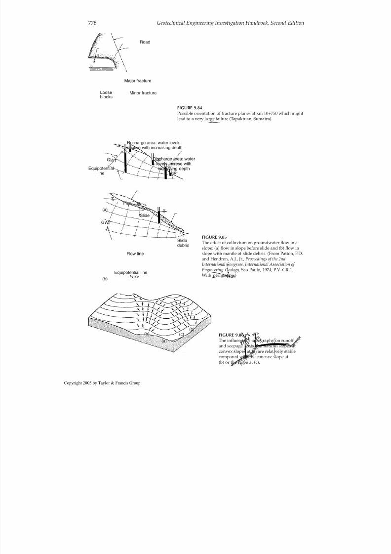
8/12/2019 CH. 9_Geologic Hazard; Landslides and Other Slope Failures
http://slidepdf.com/reader/full/ch-9geologic-hazard-landslides-and-other-slope-failures 82/136
778 Geotechnical Engineering Investigation Handbook, Second Edition
Minor fracture
Major fracture
Looseblocks
Road
FIGURE 9.84Possible orientation of fracture planes at km 10+750 which mightlead to a very large failure (Tapaktuan, Sumatra).
Recharge area: water levelsdecline with increasing depth
Equipotentialline
Slide(a)
(b)
Slidedebris
Equipotential line
Discharge area: wate rlevels increse withincreasing depth
Flow line
Flow line
G W T
G W T
FIGURE 9.85The effect of colluvium on groundwater flow in aslope: (a) flow in slope before slide and (b) flow inslope with mantle of slide debris. (From Patton, F.D.and Hendron, A.J., Jr., Proceedings of the 2ndInternational Congress, International Association of
Engineering Geology, Sao Paulo, 1974, P.V–GR 1.With permission.)
(b)(c)
(a)
(b) FIGURE 9.86The influence of topography on runoffand seepage. Cuts and natural slopes atconvex slopes at (a) are relatively stablecompared with the concave slope at(b) or the slope at (c).
opyright 2005 by Taylor & Francis Group

8/12/2019 CH. 9_Geologic Hazard; Landslides and Other Slope Failures
http://slidepdf.com/reader/full/ch-9geologic-hazard-landslides-and-other-slope-failures 83/136
regional climatic history. No slope seepage during a rainy period may be considered asvery favorable for stability, if there is no blockage from ice, colluvium, etc. On the otherhand, seepage during a dry period signifies that a substantial increase in seepage willoccur during wet periods. Toe seepage indicates a particularly dangerous condition, espe-cially during dry periods.
VegetationDensity of vegetation is an important factor in slope stability. Recently cleared upslopeareas for logging, farming, or grazing are very likely to be locations where failures willoccur in freshly made cuts, or in old cuts during severe weather conditions. Removal of vegetation permits an increase in erosion, a reduction in strength in the shallow portionsof the slope from the loss of root structure, an increase in infiltration during rainy periods,and an increase in evaporation during dry spells resulting in surface desiccation andcracking.
Certain types of vegetation may be indicators of potential instability. For example, intropical climates, such as in Brazil and Indonesia, banana plants seem to favor colluvialsoil slopes, probably because colluvium has a higher moisture content than the residualsoils in the same area.
Indications of InstabilitySurface features indicating instability include tilted or bending tree trunks, tilted polesand fence posts, tension cracks along the slope and beyond the crest, and slump andhummocky topography, as described and illustrated in Sections 9.1.2 and 9.2.
Slope Activity Degrees of ActivitySlopes reside at various degrees of activity, as discussed in Section 9.1.2, ranging throughstable slopes with no movement, early failure stages with creep and tension cracks,
Landslides and Other Slope Failures 779
RiverCut 1
Cut 2
Cut 3
At cut 1:Steep slopethin cover with colluviumhigh GWL and runoffpossible river erosion
Slope less steep and less runoffdeepwr soil cover; no colliviumdeeper GWL
At cut 3:
FIGURE 9.88Stability problems may be very much related to thecut location along a steeply inclined slope inmountainous terrain in a tropical climate, andgenerally decrease in the upslope direction.
S e e p a g e R u n o f f
S lid e
Roa d wa y
R u n o f f
FIGURE 9.87Upslope side of hillside cut tends to be much less stablethan downslope side because of runoff and seepage.
opyright 2005 by Taylor & Francis Group

8/12/2019 CH. 9_Geologic Hazard; Landslides and Other Slope Failures
http://slidepdf.com/reader/full/ch-9geologic-hazard-landslides-and-other-slope-failures 84/136
intermediate failure stages with significant movement, partial total failures with substan-tial displacement, to complete failure with total displacement.
Evidence that a slope is unstable requires an assessment of the imminence of total col-lapse, and, if movement is occurring, how much time is available for treatment and stabi-lization. Tension cracks, in particular, serve as an early warning of impending failure andare commonly associated with the early stages of many failures. Their appearance, eventogether with scarps, does not necessarily mean, however, that failure is imminent. Theslope shown in Figure 9.89 appears precipitous but the slide has moved very little over a4-year period, an interval of lower than normal rainfall (see Section 9.3.4) . Note the “nose”location; a massive slide has already occurred along the slope at the far left in the photothat closed the highway for a brief time. This “total failure,” shown in Figure 9.90,occurred where the slope shape was concave, a few hundred meters from the slope inFigure 9.89.
Movement Velocity vs. Failure
The most significant factors indicating approaching total failure for many geologic condi-tions are velocities of movement and accelerations.
Methods of monitoring slope movements, both on the surface and internally, aredescribed in Section 4.5.6. During surface monitoring, both vertical and horizontal move-ments should be measured, and evaluated in terms of velocity and acceleration. There isa lack in the literature of definitive observational data that relate velocity and accelera-tion to final or total failure in a manner suitable for formulating judgments as to whenfailure is imminent. Movement velocities before total failure and the stabilization treat-ment applied are summarized in Table 9.7 for a few cases from the literature. From theauthor’s experience and literature review, it appears that, as a rule of thumb, if a slope of
residual or colluvial soils is moving at a rate of the order of 2–5 cm/day (0.8–2.0 in./day)
780 Geotechnical Engineering Investigation Handbook, Second Edition
FIGURE 9.89Slump movement caused by cut made in residual soils for the Rio-Santos Highway (Itorna, Brazil) hasremained stable as shown for at least 4 years. (Photo taken in 1978.) The slope form is convex. The failureshown in Figure 9.90 was located around the roadway bend in the photo (left).
opyright 2005 by Taylor & Francis Group

8/12/2019 CH. 9_Geologic Hazard; Landslides and Other Slope Failures
http://slidepdf.com/reader/full/ch-9geologic-hazard-landslides-and-other-slope-failures 85/136
Landslides and Other Slope Failures 781
FIGURE 9.90Debris avalanche scar along the Rio-Santos Highway at Praia Brava, Itaorna, Brazil. The slope form wasconcave; location is around the bend from Figure 9.89.
TABLE 9.7Velocities of Slide Movements Before Total Failure and Solutions a
Location Material Movement Velocity Solution Reference
Philippine Islands Weathered rock 2 cm/day Horizontal adits Brawner (1975)(open-pit mine)
Santos, Brazil Collovium (cut) 2.5 cm/day Trenches, galleries Fox (1964)Rio de Janeiro state, Residuum (cut) 0.4–2.2 cm/day None applied, no Garga and
Brazil total failure in 20 years DeCampos (1977)Rio Santos Highway, Residuum (cut) 2–3.5 cm/day for Removal of failure Hunt (1978) (see
Brazil first 2 weeks, 30 cm/ mass Section 9.3.3)day during 6th weak,then failure
Golden slide Debris (cut) 2.5 cm/day Horizontal drains, Noble (1973)vertical wells
Pipe Organ slide Debris (cut) 5 cm/week Gravity drains Noble (1973)Vaiont, Italy Rock-mass 1 cm/week, then Kiersch (1965)translation 1 cm/day, then
20–30 cm/day andalter 3 weeks, 80 cm/day and failure
Portuguese Bend Lateral spreading 1956–1957, 5–12 cm/yr None Easton (1973)1958, 15–60 cm/yr1961–1968, 1–3m/yr1968, dramatic increase,
houses destroyed1973, 8 cm/day during
dry season1973, 10 cm/day during
wet season1973, 15 cm/day duringheavy rains
No total mass failure
a From examples given in Chapter 9.
opyright 2005 by Taylor & Francis Group

8/12/2019 CH. 9_Geologic Hazard; Landslides and Other Slope Failures
http://slidepdf.com/reader/full/ch-9geologic-hazard-landslides-and-other-slope-failures 86/136
during a rainy season with the probability of storms, and if the velocity is increasing, finalfailure is imminent and may occur during the first heavy rain, or at some time during therainy season. The following two case histories relate slope movements to total failure.
Case 1: A roadway cut made in residual soils in the coastal mountains of Brazil contin-ued to show instability through creep, tension cracks, small slumps, and periodicencroachment on the roadway for a period of several years. An intermediate failure stageoccurred on November 29, 1977, after a weekend of moderately heavy rain and a periodduring which the highway department had been removing material from the slope toe.Figure 9.91, a photo taken from a helicopter about 10 days after the failure, illustrates thegeneral conditions. Tension cracks have opened at the base of the forward transmissiontower, a large scarp has formed at midslope, and the small gabion wall at the toe hasfailed.
Figure 9.92 illustrates the tension crack and the distortion in the transmission towershown in Figure 9.91. The maximum crack width was about 30 cm (12 in.) and the scarpwas as high as 50 cm (20 in.). Slope movement measurements were begun immediately by
optical survey and the transmission lines were quickly transferred to a newly constructedtower situated farther upslope.For the first 2 weeks after the initial movement, a period of little rainfall, the vertical
drop along the scarp was about 2–3.5 cm/day (0.8–1.4 in./day). In 5 weeks, with occasionalrainy periods, the scarp had increased to 3 m (10 ft). Finally, after a weekend of heavy rainsthe slide failed totally in its final stage within a few hours, leaving a scarp about 30m(100 ft) in height as shown in Figure 9.93 , and partially blocking the roadway. Excavationremoved the slide debris, and 2 years afterward the high scarp still remained. The towerin the photo was again relocated farther upslope. Although future failures will occur, theywill be too far from the roadway to cover the pavement.
Remediating the slope by permitting failure is an example of one relatively low-costtreatment method. Cutting material from the head of the slide would be an alternatemethod, but there was concern that perhaps time for construction prior to total failure
782 Geotechnical Engineering Investigation Handbook, Second Edition
FIGURE 9.91Rotational slide at Muriqui, Rio de Janeiro, Brazil, initiated by the road cut, had been active for 4 years. Majormovements began after a weekend of heavy rains, endangering the transmission tower. Tension crack anddistorted transmission tower shown in the inset, Figure 9.92.
opyright 2005 by Taylor & Francis Group

8/12/2019 CH. 9_Geologic Hazard; Landslides and Other Slope Failures
http://slidepdf.com/reader/full/ch-9geologic-hazard-landslides-and-other-slope-failures 87/136
would be inadequate. Considering the slope activity, weather conditions, costs, and con-struction time, a retaining structure was considered as not practical.
Case 2: Another situation is similar to that described in Case 1 although the volume of the failing mass is greater. A 25° slope of residual soil has been moving for 20 years sinceit was activated by a road cut (Garga and DeCampos, 1977). Each year during the rainy
season movement occurs at a velocity measured by slope inclinometer ranging from0.4–2.2 cm/day (0.2–0.9 in./day). The movement causes slide debris to enter the roadway,from which it is removed. During the dry season movement ceases, and as of the time of the report (1977), total failure had not occurred.
9.3.4 Weather Factors
Correlations between Rainfall and Slope Failures
Significance
Ground saturation and rainfall are the major factors in slope failures and influence theirincidence, form, and magnitude. Evaluating rainfall data are very important for anticipat-ing and predicting slope failures. Three aspects are important:
1. Climatic cycles over a period of years, i.e., high annual precipitation vs. lowannual precipitation
2. Rainfall accumulation in a given year in relationship to normal accumulation3. Intensities of given storms
Cumulative Precipitation vs. Mean Annual Precipitation
A study of the occurrence of landslides relative to the cumulative precipitation record upto the date of failure as a percentage of the mean annual precipitation (termed the cyclecoefficient Cc) was made by Guidicini and Iwasa (1977). The study covered nine areas of the mountainous coastal region of Brazil, which has a tropical climate characterized by awet season from January through March and a dry season, June through August.
Landslides and Other Slope Failures 783
FIGURE 9.93Total collapse of slope shown in Figure 9.91 left a high head scarp and temporarily closed the roadway. Failureoccurred 6 weeks later during the rainy season after several days of heavy rains.
opyright 2005 by Taylor & Francis Group

8/12/2019 CH. 9_Geologic Hazard; Landslides and Other Slope Failures
http://slidepdf.com/reader/full/ch-9geologic-hazard-landslides-and-other-slope-failures 88/136
Cumulative precipitation increases the ground saturation and a rise in the water table.A rainstorm occurring during the dry season or at the beginning of the wet season willhave a lesser effect on slope stability than a storm of the same intensity occurring near theend of the wet season. A plot by month of the occurrence of failures as a function of thecycle coefficient is given in Figure 9.94 . It is seen that the most catastrophic events occurtoward the end of the rainy season, when the cumulative precipitation is higher than themean annual.
Regarding rainfall intensity, Guidicini and Iwasa concluded that:
● Extremely intense rainfalls, about 12% greater than the mean annual rainfall (300mm in 24–72 h) or more, can cause natural slope failures in their area, regardlessof the previous rainfall history.
● Intense rainfalls, up to 12% of the mean annual, where the precipitation cycle isnormal or higher, will cause failures, but if the preceding precipitation level islower than the mean annual, failures are not likely even with intensities to 12%.
●
Rainfalls of 8% or less of annual precipitation will generally not cause failures,regardless of the preceding precipitation, because the gradual increase in the sat-uration level never reaches a critical magnitude.
● A danger level chart (Figure 9.95) was prepared by Guidicini and Iwasa for eachstudy area, intended to serve communities as a guide for assessing failure haz-ard in terms of the mean cumulative precipitation for a given year.
Such data can be used for temporarily closing mountain roadways, subject to slope fail-ures, when large storms are expected during the rainy season. At the least warnings signscan be placed.
Evaluating Existing Cut Slope Stability
GeneralIt is often necessary to evaluate a cut slope that appears stable to formulate judgments asto whether it will remain so. If a cut slope has been subjected during its lifetime to condi-
784 Geotechnical Engineering Investigation Handbook, Second Edition
Serra of caraguatatuba
Imigranates highwayAnchieta highwaySerra of maranguapeRiode janeiroSea of ArarasSouth of minas gerais
Santos lowlands
Tubarao valley
Land slides
0 Jul. Aug. Sep. Oct. Nov. Dec.
+
x
Jan. Feb. Mar. Apr. May. Jun.
0.5
1.0 C c
1.5
2.0
Zone
ABCD
6275214
648160
10067310
Number ofrainfallevents
Number oflandslide
eventsPercent-
age
Z o n e A Z o n e
B
Z o n e C Z o n e D
Legend
60 days
15 days30 days
Displacement
Catastrophic events
Plot of the ''cycle coefficient'' (C c) for all the selected rainfall events
FIGURE 9.94Comparison of landslide events and rainfall cycle coefficient Cc for coastal mountains of Brazil. (FromGuidicini, G. and Iwasa, O.Y., Bull. Int. Assoc. Eng. Geol.,16, 13–20, 1977. With permission.)
opyright 2005 by Taylor & Francis Group

8/12/2019 CH. 9_Geologic Hazard; Landslides and Other Slope Failures
http://slidepdf.com/reader/full/ch-9geologic-hazard-landslides-and-other-slope-failures 89/136

8/12/2019 CH. 9_Geologic Hazard; Landslides and Other Slope Failures
http://slidepdf.com/reader/full/ch-9geologic-hazard-landslides-and-other-slope-failures 90/136
lanches, slides, and flows. A relationship among the number of rock falls, mean monthlytemperature, and mean monthly precipitation is given in Figure 9.96 . It is seen that thehighest incidence for rock falls is from November through March in the Fraser Canyon of British Columbia.
9.3.5 Hazard Maps and Risk Assessment
Purpose Degrees of slope-failure hazards along a proposed or existing roadway or other develop-ment can be illustrated on slope hazard maps. Such maps provide the basis not only forestablishing the form of treatment required, but also for establishing the degree of urgencyfor such treatment in the case of existing works, or the programming of treatment forfuture works. They represent the product of a regional assessment.
Hazard Rating SystemsIn recent years, various organizations have developed hazard rating systems. In theUnited States, the system apparently most commonly used is the “Rockfall Hazard RatingSystem” (RHRS) developed for the Federal Highway Administration by the Oregon StateHighway Department (Pierson et al., 1990). Highway departments use the RHRS to inven-tory and classify rock slopes according to their potential hazard to motorists, and to iden-tify those slopes that present the greatest degree of hazard and formulate cost estimatesfor treatments (McKown, 1999).
Some states, such as West Virginia (Lessing et al., 1994), have prepared landslide hazardmaps. The Japanese have studied the relationships between earthquake magnitude and
epicenter distance to slope failures in Japan and several other countries and have pro-posed procedures for zoning the hazard (Orense, 2003).
Example
The ProblemA 7 -km stretch of existing mountain roadway with a 20-year history of slope failures,including rotational slides, debris slides, avalanches, and rock falls, was mapped in detailwith respect to slope stability to provide the basis for the selection of treatments and theestablishment of treatment priorities. A panoramic photo of the slopes in the higher ele-
vations along the roadway is given in Figure 9.97.
786 Geotechnical Engineering Investigation Handbook, Second Edition
Mean monthlyprecipitation
M e a n m o n t h l y p r e c e p i t a t i o n
( i n )
32 ° F
M e a n m o n t
h l y t e m p e r a u r e ,
F ° n u m
b e r
o f r o c k f a l l s
Total numberof rock falls
Mean monthlytemperature
807060504030
2010
0
807060504030
20100
Jan.F M A M JMonth (1933 to 1970)
J A S O NDec.
FIGURE 9.96Number of rockfalls, mean monthly temperature, andmean monthly precipitation in the Fraser Canyon of British Columbia for 1933–1970. (Peckover, 1975; fromPiteau, D.R., Reviews in Engineering Geology,Vol. III,Coates, D.R., Ed., Geologic Society of America,Boulder, Colorado, 1977, pp. 85–112. Withpermission.)
opyright 2005 by Taylor & Francis Group
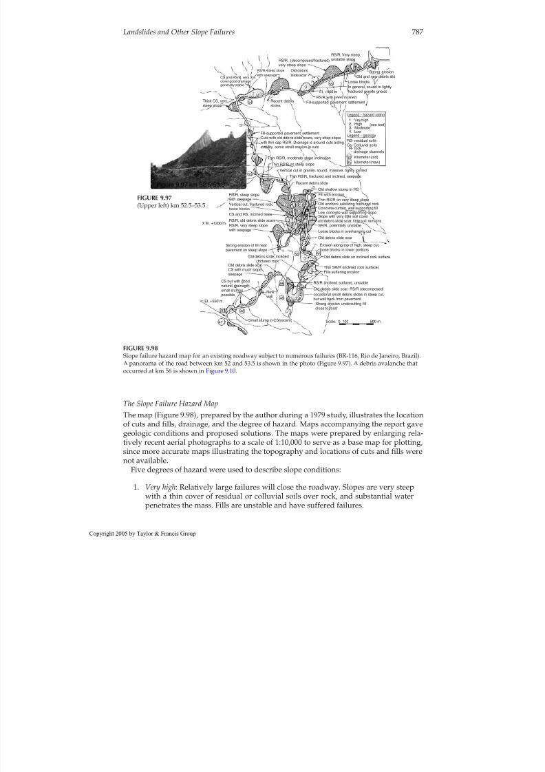
8/12/2019 CH. 9_Geologic Hazard; Landslides and Other Slope Failures
http://slidepdf.com/reader/full/ch-9geologic-hazard-landslides-and-other-slope-failures 91/136
The Slope Failure Hazard MapThe map (Figure 9.98), prepared by the author during a 1979 study, illustrates the locationof cuts and fills, drainage, and the degree of hazard. Maps accompanying the report gavegeologic conditions and proposed solutions. The maps were prepared by enlarging rela-tively recent aerial photographs to a scale of 1:10,000 to serve as a base map for plotting,since more accurate maps illustrating the topography and locations of cuts and fills werenot available.
Five degrees of hazard were used to describe slope conditions:1. Very high: Relatively large failures will close the roadway. Slopes are very steep
with a thin cover of residual or colluvial soils over rock, and substantial waterpenetrates the mass. Fills are unstable and have suffered failures.
Landslides and Other Slope Failures 787
Thick CS, verysteep slope
CS and RS/R, very thincover good drainagegenerally stable
RS/R, steep slopewith seepage
RS/R, (decomposed/fractured)very steep slope
Old debrisslide scar ?
55
224
RS/R, Very steep,unstable slope
54
3
31
3
3
53 3
3
1
51
52
33
33
3
33
33
3
3
3
33
4
4
4
4
450 95
96
49
48
Small slump in CS(recent)
Old debris slide scarCS with much slopeseepage
Old debris slide, inclidedfrctured rock
Strong erosion of fill nearpavement on steep slope
RS/R, old debris slide scars
CS and RS, inclined trees
Vertical cut, fractured rock,loose blocks
RS/R, steep slopewith seepage
RS/R, very steep slopewith seepage
X EI. +1200 m
CS but with goodnatural drainage,small slumpspossible
EI. +550 m
Newwall
97
47,7
4
4
4
44
4
2
2
2
1
2
2
2
2
2
2
2
2
3
4
3
3
Old and new debris slidStrong erosion
Loose blocks
EI. +900 mRS/R with trees inclined
Fill-supported pavement settlement
Legend - hazard rating
Legend - geologyRS- residual soilsCs- Colluvial soils
R- rock- drainage channels
kilometer (old)kilometer (new)
5595
(see text)
In general, sound to lightlyfractured granite gneiss
1
1
Recent debrisslides
Fill-supported pavement settlementCuts with old debris slide scars, very sttep slopewith thin cap RS/R. Drainage is around cuts aidingstability. some small erosion in cuts
Thin RS/R, moderate slope inclination
Thin RS/R on steep slope
Old shallow slump in RS
Thin RS/R on very steep slope
Old debris slide on inclined rock surface
RS/R (inclined surface), unstable
Scale: 0 100 500 m
Strong erosion undercutting fillclose to road
occasional small debris slides in steep cut,but well back from pavement
Old debris slide scar, RS/R (decomposed)
Fills suffering erosion
Old debris slide scar
Thin SR/R (inclined rock surface)
Erosion along top of high, steep cut,loose blocks in lower portions
Loose blocks in overhanging cut
Slope with very little soil coverold debris slide scar, little soil remainsSR/R, potentially unstable
Low concrete wall supporting slopeConcrete curtain, wall supporting fillOld anchors sabilizing fractured rock
Fill with erosion
Recent debris slide
Thin RS/R, fractured and inclined, seepageVertical cut in granite, sound, massive, tightly jointed
1. Vey high2. High3. Moderate4. Low
Figure 9.97 km 52.5-53.5
FIGURE 9.98Slope failure hazard map for an existing roadway subject to numerous failures (BR-116, Rio de Janeiro, Brazil).A panorama of the road between km 52 and 53.5 is shown in the photo (Figure 9.97). A debris avalanche thatoccurred at km 56 is shown in Figure 9.10.
FIGURE 9.97(Upper left) km 52.5–53.5.
opyright 2005 by Taylor & Francis Group

8/12/2019 CH. 9_Geologic Hazard; Landslides and Other Slope Failures
http://slidepdf.com/reader/full/ch-9geologic-hazard-landslides-and-other-slope-failures 92/136
2. High: Relatively large failures probably will close the road. Failures haveoccurred already in residual or colluvial soils and in soils over rock on moder-ately steep slopes. Fills are unstable.
3. Moderate: In general, failures will not close the road completely. Relatively smallfailures have occurred in residual soils on steep slopes, in colluvial soils on mod-erate slopes with seepage, in vertical slopes with loose rock blocks, and in slopeswith severe erosion.
4. Low: Low cuts, cuts in strong soils or stable rock slopes, and fills. Some erosion isto be expected, but in general slopes are without serious problems.
5. No Hazard: Level ground, or sound rock, or low cuts in strong soils.
Note: Several years after the study, during heavy rains, a debris avalanche occurred atkm 52.9 (a high-hazard location) carrying a minibus downslope over the side of the road-way resulting in a number of deaths
9.4 Treatment of Slopes
9.4.1 General Concepts
Selection Basis
Basic FactorsThe first factor to consider in the selection of a slope treatment is its purpose, which can
be placed in one of two broad categories:
● Preventive treatments which are applied to stable, but potentially unstable, nat-ural slopes or to slopes to be cut or to side-hill fills to be placed
● Remedial or corrective treatments which are applied to existing unstable, mov-ing slopes or to failed slopes
Assessment is then made of other factors, including the degree of the failure hazard andrisk (see Section 9.1.3 ) and the slope condition, which can be considered in four generalgroupings as discussed below.
Slope ConditionsPotentially unstable natural slopes range from those subjects to falls or slides where devel-opment along the slope or at its base can be protected with reasonable treatments, to thosewhere failures may be unpreventable and will have disastrous consequences. The poten-tial for the latter failures may be recognizable, but since it cannot be known when the nec-essary conditions may occur, the failures are essentially unpredictable. Some examples of slope failures that could not have been prevented with any reasonable cost include thoseat Nevada Huascaran in the Andes that destroyed several towns (see Section 9.2.8 ), theAchocallo mudflow near La Paz (see Section 9.2.11 ), and the thousands of debris ava-
lanches and flows that have occurred in a given area during heavy storms in mountainousregions in tropical climates (see Section 9.2.8).Unstable natural slopes undergoing failure may or may not require treatment depending
upon the degree of hazard and risk, and in some instances, such as Portuguese Bend (seeSection 9.2.6) , stabilization may not be practical because of costs.
788 Geotechnical Engineering Investigation Handbook, Second Edition
opyright 2005 by Taylor & Francis Group

8/12/2019 CH. 9_Geologic Hazard; Landslides and Other Slope Failures
http://slidepdf.com/reader/full/ch-9geologic-hazard-landslides-and-other-slope-failures 93/136
Unstable cut slopes in the process of failure need treatment, but stabilization may not beeconomically practical.
New slopes formed by cutting or filling may require treatment by some form of stabi-lization.
Initial AssessmentAn initial assessment is made of the slope conditions, the degree of the hazard, and therisk. There are then three possible options to consider for slope treatment:
● avoid the high-risk hazard, or● accept the failure hazard, or● stabilize the slope to eliminate or reduce the hazard.
Treatment Options
Avoid the High-Risk HazardConditions: Where failure is essentially not predictable or preventable by reasonable meansand the consequences are potentially disastrous, as in mountainous terrain subject to mas-sive planar slides or avalanches, or slopes in tropical climates subject to debris avalanches,or slopes subject to liquefaction and flows, the hazard should be avoided.
Solutions: Avoid development along the slope or near its base and relocate roadways orrailroads to areas of lower hazard where stabilization is feasible, or avoid the hazard bytunneling.
Accept the Failure Hazard
Conditions: Low to moderate hazards, such as partial temporary closure of a roadway, or afailure in an open-pit mine where failure is predictable but prevention is considereduneconomical, may be accepted.
Open-pit mines: Economics dictates excavating the steepest slope possible to minimizequantities to be removed, and most forms of treatment are not feasible; therefore, the haz-ard is accepted. Slope movements are monitored to provide for early warning and evacu-ation of personnel and equipment. In some instances, measures may be used to reduce thehazard where large masses are involved, but normally failures are simply removed withthe equipment available.
Roadways: Three options exist besides avoiding the hazard, i.e., accept the hazard,
reduce the hazard, or eliminate it. Acceptance is based on an evaluation of the degree of hazard and the economics of prevention. In many cases involving relatively small volumesfailure is self-correcting and most, if not all, of the unstable material is removed from theslope by the failure; it only remains to clean up the roadway. These nuisance failures com-monly occur during or shortly after construction when the first adverse weather arrives.The true economics of this approach, however, depends on a knowledgeable assessmentof the form and magnitude of the potential failure, and assurance that the risk is low tomoderate. Conditions may be such that small failures will evolve into very large ones, orthat a continuous and costly maintenance program may be required. Public opinionregarding small but frequent failures of the nuisance type also must be considered.
Eliminate or Reduce the HazardWhere failure is essentially predictable and preventable, or is occurring or has occurredand is suitable for treatment, slope stabilization methods are applied. For low- to moder-ate-risk conditions, the approach can be either to eliminate or to reduce the hazard,
Landslides and Other Slope Failures 789
opyright 2005 by Taylor & Francis Group

8/12/2019 CH. 9_Geologic Hazard; Landslides and Other Slope Failures
http://slidepdf.com/reader/full/ch-9geologic-hazard-landslides-and-other-slope-failures 94/136
depending on comparative economics. For high-risk conditions the hazard should beeliminated.
Slope Stabilization
MethodsSlope stabilization methods may be placed in five general categories:
1. Change slope geometry to decrease the driving forces or increase the resistingforces.
2. Control surface water infiltration to reduce seepage forces.3. Control internal seepage to reduce the driving forces and increase material
strengths.4. Provide retention to increase the resisting forces.5. Increase soil strength with injections. In a number of instances the injection of
quicklime slurry into predrilled holes has arrested slope movements as a resultof the strength increase from chemical reaction with clays (Handy and Williams,1967; Broms and Bowman, 1979). Strength increase in saltwater clays, however,was found to be low.
Stabilization methods are illustrated generally in Figure 9.99 and summarized in Table9.8 with respect to conditions and general purpose. “General Purpose” indicates whetherthe aim is to prevent failure or to treat the slope by some remedial measure.
Selection
In the selection of the stabilization method or methods, consideration is given to a num- ber of factors including:
● Material types composing the slope and intensity and orientation of the discon-tinuities
● Slope activity● Proposed construction, whether cut or side-hill● Form and magnitude of potential or recurring failure (summary of preventive
and remedial measures for the various failure forms is given in Table 9.9 )
790 Geotechnical Engineering Investigation Handbook, Second Edition
Lined drainage ditch upslope
Reduce slopeinclination
Retain slopewith berm,buttress,or wall
Control runoff withlined drains
Soil
Plant vegetation
Shotcrete or wallin weak zone
Rock bolts orcable anchors
Rock
Maintain slopevegetation
Subhorizontalgravity drainsor galleries
Toedrain
(a) (b)
Phreatic zone
pervious zone
I m pe r v i o u s
z o ne
Seal fracturesVertical gravity wells
Pumped wells
FIGURE 9.99The general methods of slope stabilization: (a) control of seepage forces and (b) reducing the driving forces andincreasing the resisting forces.
opyright 2005 by Taylor & Francis Group

8/12/2019 CH. 9_Geologic Hazard; Landslides and Other Slope Failures
http://slidepdf.com/reader/full/ch-9geologic-hazard-landslides-and-other-slope-failures 95/136
● Time available for remedial work on failed slopes, judged on the basis of slopeactivity, movement velocity and acceleration, and existing and near-futureweather conditions
● Degree of hazard and risk● Necessity to reduce or eliminate the hazard
Hazard EliminationThe hazard can be eliminated by sufficient reduction of the slope height and inclinationcombined with an adequate surface drainage system or by retention.
Retention of rock slopes is accomplished with pedestals, rock bolts, bolts and straps, orcable anchors; retention of soil slopes is accomplished with the addition of adequate mate-rial at the toe of the slope or with properly designed and constructed walls.
Landslides and Other Slope Failures 791
TABLE 9.8Summary of Slope Treatment Methods for Stabilization
Treatment Conditions General Purpose (Preventive or Remedial)
Change Slope Geometry
Reduce height Rotational slides Prevent/treat during early stagesReduce Inclination All soil/rock Prevent/treat during early stagesAdd weight to toe Soils Treat during early stages
Control Surface Water
Vegetation Soils PreventSeal cracks Soil/rock Prevent/treat during early stagesDrainage system Soil/decomposing rock Prevent/treat during early stages
Control Internal Seepage
Deep wells Rock masses Temporary treatmentVertical gravity drains Soil/rock Prevent/treat during early stagesSubhorizontal drains Soil/rock Prevent/treat early to Intermediate stagesGalleries Rock/strong soils Prevent/treat during early stagesRelief wells or toe trenches Soils Treat during early stagesInterceptor trench drains Soils (cuts/fills) Prevent/treat during early stagesBlanket drains Soils (fills) PreventElectroosmosis a Soils (silts) Prevent/treat during early stages: temporarilyChemical a Soils (clays) Prevent/treat during early stages
Retention
Concrete pedestals Rock overhang PreventRock bolts Jointed or sheared rock Prevent/treat sliding slabsConcrete straps and bolt. Heavily jointed or soft rock PreventCable anchors Dipping rock beds Prevent/treat early stagesWire meshes Steep rock slopes Contain fallsConcrete impact wells Moderate slopes Contain sliding or rolling blocksShotcrete Soft or jointed rock PreventRock-filled buttress Strong soils/soft rock Prevent/treat during early stagesGabion wall Strong soils/soft rock Prevent/treat during early stagesCrib wall Moderately strong soils PreventReinforced earth wall Soils/decomposing rock PreventConcrete gravity walls Soils to rock PreventAnchored concrete curtain walls Soils/decomposing rock Prevent/treat—early to intermediate stagesBored or root piles Soils/decomposing rock Prevent/treat—early stages
a Provides strength increase .
opyright 2005 by Taylor & Francis Group

8/12/2019 CH. 9_Geologic Hazard; Landslides and Other Slope Failures
http://slidepdf.com/reader/full/ch-9geologic-hazard-landslides-and-other-slope-failures 96/136
Hazard ReductionThe hazard can be decreased by partially reducing the height and inclination or addingmaterial at the toe; by planting vegetation, sealing cracks, installing surface drains, andshotcreting rock slopes; and by controlling internal seepage. In the last case, one can never
be certain that drains will not clog, break off during movements, or be overwhelmed byextreme weather conditions.
Time FactorWhere slopes are in the process of failing, the time factor must be considered. Time maynot be available for carrying out measures that will eliminate the hazard; therefore, thehazard should be reduced and perhaps eliminated at a later date. The objective is to arrestthe immediate movement. To the extent possible, treatments should be performed during
792 Geotechnical Engineering Investigation Handbook, Second Edition
TABLE 9.9Failure Forms: Typical Preventive and Remedial Measures
Failure Form Prevention daring Construction Remedial Measures
Rock fall Base erosion protection Permit fall, clean roadwayControlled blasting excavation Rock bolts and strapsRock bolts and straps, or cables Concrete supportsConcrete supports, large masses Remove loose blocksRemove loose blocks Impact wallsShotcrete weak strata
Soil fall Base erosion protection Retention
Planar rock slide Small volume: remove or bolt Permit slide, clean roadwayModerate volume: provide stable Remove to stable inclination or bolt
inclination or bolt to retainLarge volume: install internal Install internal drainage or relocate
drainage or relocate to avoid to avoidRotational rock slide Provide stable inclination and Remove to stable inclination
surface drainage system Provide surface drainageInstall internal drainage Install internal drains
Planar (debris) slides Provide stable inclination and Allow failure and clean roadwaysurface drainage control Use preventive measures
Retention for small to moderatevolumes
Large volumes: relocate
Rotational soil slides Provide stable inclination and surface Permit failure, clean roadwaydrainage control, or retain Remove to stable inclination,
provide surface drainage, or retain
Subhorizontal drains for largevolumesFailure by lateral Small scale: retain Small scale: retain.
spreading Large scale: avoid and relocate, Large scale: avoidprevention difficult
Debris avalanche Prediction and prevention difficult Permit failure, clean roadway:Treat as debris slide eventually self-correctingAvoid high-hazard areas Otherwise relocate
Small scale: retain or removeFlows Prediction and prevention difficult Small scale: remove
Avoid susceptible areas Large scale: relocate
opyright 2005 by Taylor & Francis Group

8/12/2019 CH. 9_Geologic Hazard; Landslides and Other Slope Failures
http://slidepdf.com/reader/full/ch-9geologic-hazard-landslides-and-other-slope-failures 97/136
the dry season when movements will not close trenches, break off drains, or result in evenlarger failures when cuttings are made.
In general, the time required for various treatment measures are as follows:
● Sealing surface cracks and constructing interceptor ditches upslope are per-formed within several days, at most.
● Excavation at the head of a slide or the removal of loose blocks may require 1 to2 weeks.
● Relief of internal water pressures may require 1 to 4 weeks for toe drains andtrenches and 1 to 2 months for the installation of horizontal or vertical drains.
● Counterberms and buttresses at the toe require space, but can be constructedwithin 1 to 2 weeks.
● Retention with concrete walls can require 6 months or longer.
9.4.2 Changing Slope Geometry
Natural Slope Inclinations
SignificanceIn many cases, the natural slope represents the maximum long-term inclination, but inother cases the slope is not stable. The inclination of existing slopes should be noted dur-ing field reconnaissance, since an increase in inclination by cutting may result in failure.
Some examples of natural slope inclinations
● Hard, massive rocks: Maximum slope angle and height is controlled by the con-centration and orientation of joints and by seepage. The critical angle for highslopes of hard, massive rock with random joint patterns and no seepage actingalong the joints is about 70° (Terzaghi, 1962).
● Interbedded sedimentary rocks: Extremely variable, depending upon rock type, cli-mate, and bedding thickness as well as joint orientations and seepage conditions.Along the river valleys, natural excavation may have reduced stresses suffi-ciently to permit lateral movement along bedding planes and produce bedding-plane mylonite shear zones. On major projects such shears should be assumed toexist until proven otherwise. The slickensides illustrated in Figure 6.54 are prob-ably shale mylonite.
● Clay shales: 8 to 15°, but often unstable. When interbedded with sandstones, 20 to
45° (see Section 6.7.3 ).● Residual soils: 30 to 40°, depending upon parent rock type and seepage.● Colluvium: 10 to 20°, and often unstable.● Loess: Often stands vertical to substantial heights.● Sands: dry and “clean,” are stable at the angle of repose ( i φ).● Clays: Depends upon consistency, whether intact or fissured, and the slope
height.● Sand–clay mixtures: Often stable at angles greater than repose as long as seepage
forces are not excessive.
Cut Slopes in Rock ExcavationThe objective of any cut slope is to form a stable inclination without retention. Careful
blasting procedures are required to avoid excessive rock breakage resulting in numerous
Landslides and Other Slope Failures 793
opyright 2005 by Taylor & Francis Group

8/12/2019 CH. 9_Geologic Hazard; Landslides and Other Slope Failures
http://slidepdf.com/reader/full/ch-9geologic-hazard-landslides-and-other-slope-failures 98/136
blocks. Line drilling and presplitting during blasting operations minimize disturbance of the rock face.
Typical Cut InclinationsHard masses of igneous or metamorphic rocks, widely jointed, are commonly cut to 1H:4V(76°) as shown in Figure 9.100. Hard rock masses with joints, shears, or bedding repre-senting major discontinuities and dipping downslope are excavated along the dip of thediscontinuity as shown in Figure 9.101 , although all material should be removed until theoriginal slope is intercepted. If the dip is too shallow for economical excavation, slabs can
be retained with rock bolts (see Section 9.4.6) . Hard sedimentary rocks with bedding dipping vertically and perpendicularly to the
face as in Figure 9.102 or dipping into the face; or horizontally interbedded hard sandstone
794 Geotechnical Engineering Investigation Handbook, Second Edition
IIB
IIA
IC
IBIA
2:14m
5m
5m
1½
11
¼1
1
0
10m
20m
30m
40m
50m
II Weathered rock
I Residual soil 1. saprolite bench (optional)
2. Weathered rock bench
3.Rock bench
III Unweathered rock
IA, IBICIIAIIBIII
(305 . 365+ m/s)(455 . 1060 m/s)(1060 . 1985 m/s)(1985 . 3050 m/s)(3050 . 500 m/s)
1000 . 1200+ fps1500 .3500 fps3500 .65006500 .10,00010,000 . 18,000+
Typical seismic velocities
Note: Water = 1500 m/s
FIGURE 9.100Typical cut slope angles for variousrock and soil conditions. (From Deere,D.U. and Patton, F.D., Proceedings of ASCE, 4th Pan American Conferenceon Soil Mechanics and FoundationEngineering, San Juan, P.R., 1971,
pp. 87–170. With permission.)
FIGURE 9.101The face of the major joint surface in siltstone is stable but the overhanging blocks will fail along the samesurface unless removed or retained (Sidikalang, Sumatra).
opyright 2005 by Taylor & Francis Group

8/12/2019 CH. 9_Geologic Hazard; Landslides and Other Slope Failures
http://slidepdf.com/reader/full/ch-9geologic-hazard-landslides-and-other-slope-failures 99/136
and shale (see Figure 6.48) are often cut to 1H:4V. The shale beds in Figure 6.48 should beprotected from weathering with shotcrete or gunite if they have expansive properties orare subjected to intense fracturing and erosion from weathering processes. Note that the
steeper the cut slope the more resistant it is to erosion from rainfall.Clay shale, unless interbedded with sandstone, is often excavated to 6H:1V (9.5°).Weathered or closely jointed masses (except clay shale and dipping major discontinu-
ities) require a reduction in inclination to between 1H:2V 1H:1V (63–45°) depending onconditions, or require some form of retention.
Landslides and Other Slope Failures 795
FIGURE 9.102Folded, vertical beds in highly fractured, hard arenaceous shale, are stable in near-vertical cuts (Sidikalang,Sumatra). Decreasing the slope inclination would increase susceptibility to erosion.
opyright 2005 by Taylor & Francis Group

8/12/2019 CH. 9_Geologic Hazard; Landslides and Other Slope Failures
http://slidepdf.com/reader/full/ch-9geologic-hazard-landslides-and-other-slope-failures 100/136
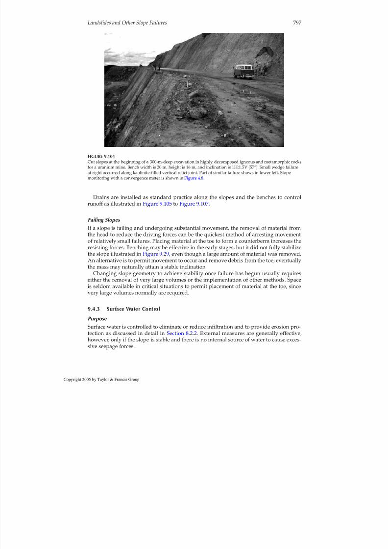
8/12/2019 CH. 9_Geologic Hazard; Landslides and Other Slope Failures
http://slidepdf.com/reader/full/ch-9geologic-hazard-landslides-and-other-slope-failures 101/136
Drains are installed as standard practice along the slopes and the benches to controlrunoff as illustrated in Figure 9.105 to Figure 9.107.
Failing Slopes If a slope is failing and undergoing substantial movement, the removal of material fromthe head to reduce the driving forces can be the quickest method of arresting movementof relatively small failures. Placing material at the toe to form a counterberm increases theresisting forces. Benching may be effective in the early stages, but it did not fully stabilizethe slope illustrated in Figure 9.29, even though a large amount of material was removed.An alternative is to permit movement to occur and remove debris from the toe; eventually
the mass may naturally attain a stable inclination.Changing slope geometry to achieve stability once failure has begun usually requireseither the removal of very large volumes or the implementation of other methods. Spaceis seldom available in critical situations to permit placement of material at the toe, sincevery large volumes normally are required.
9.4.3 Surface Water Control
Purpose Surface water is controlled to eliminate or reduce infiltration and to provide erosion pro-
tection as discussed in detail in Section 8.2.2. External measures are generally effective,however, only if the slope is stable and there is no internal source of water to cause exces-sive seepage forces.
Landslides and Other Slope Failures 797
FIGURE 9.104Cut slopes at the beginning of a 300-m-deep excavation in highly decomposed igneous and metamorphic rocksfor a uranium mine. Bench width is 20 m, height is 16 m, and inclination is 1H:1.5V (57°). Small wedge failureat right occurred along kaolinite-filled vertical relict joint. Part of similar failure shows in lower left. Slopemonitoring with a convergence meter is shown in Figure 4.8.
opyright 2005 by Taylor & Francis Group

8/12/2019 CH. 9_Geologic Hazard; Landslides and Other Slope Failures
http://slidepdf.com/reader/full/ch-9geologic-hazard-landslides-and-other-slope-failures 102/136
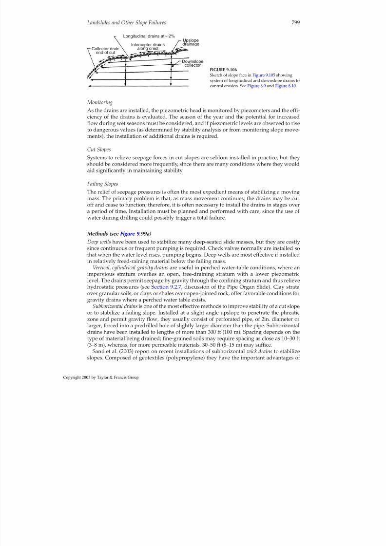
8/12/2019 CH. 9_Geologic Hazard; Landslides and Other Slope Failures
http://slidepdf.com/reader/full/ch-9geologic-hazard-landslides-and-other-slope-failures 103/136

8/12/2019 CH. 9_Geologic Hazard; Landslides and Other Slope Failures
http://slidepdf.com/reader/full/ch-9geologic-hazard-landslides-and-other-slope-failures 104/136
stretching and not rupturing during deformation, and are resistant to clogging.Installation proceeds with a disposal plate attached to the end of a length of wick drainthat is inserted into a drive pipe. The pipe, which can be wire line drill rod, is pushed intothe slope with a bulldozer or backhoe. Additional lengths of wicks and pipe are attachedand driven into the slope. When the final length is installed, the drive pipe is extracted.
Drainage galleries are very effective for draining large moving masses but their installa-tion is difficult and costly. They are used mostly in rock masses where roof support is lessof a problem than in soils. Installed below the failure zone to be effective, they are often
backfilled with stone. Vertical holes drilled into the galleries from above provide fordrainage from the failure zone into the galleries.
Interceptor trench drains or slots are installed along a slope to intercept seepage in a cut orsliding mass, but they must be sufficiently deep. As shown in Figure 9.107, slotted pipe islaid in the trench bottom, embedded in sand, and covered with free-draining material,then sealed at the surface (see Section 8.4.4) . The drain bottom should be sloped to providefor gravity drainage to a discharge point. Interceptor trench drains are generally not prac-
tical on steep, heavily vegetated slopes because installation of the drains and access roadsrequires stripping the vegetation, which will further decrease stability.Relief trenches or slotsrelieve pore pressures at the slope toe (see Section 8.4.4, Discussion
of Earth Dams). They are relatively simple to install. Excavation should be made in sec-tions and quickly backfilled with stone so as not to reduce the slope stability and possiblycause a total failure. Generally, relief trenches are most effective for slump slides ( Figure9.25) where high toe seepage forces are the major cause of instability.
Electro-osmosis(see Section 8.4.3) has been used occasionally to stabilize silts and clayeysilts, but the method is relatively costly, and not a permanent solution unless operation ismaintained.
800 Geotechnical Engineering Investigation Handbook, Second Edition
Bench as required for equipmentaccess to excavate. Backfill withcompacted sand and gravel
Backfill sand and gravelmax. size 3in. with less than5% passing #200 sieve or
equivalent crushed stonecompact in 12 in. liftsCompact each lift with2 passes of plate vibrator.
Geofilter fabric (nonwovenmirafi 140, BIDIM. or equal)
Note: Slope trench and PVCpipe at a minimummof 6 in. per 100 ft.
Scale (ft)
4" min. clearanceall sides
4 ft (max.)
6 f t ( m a x .
) 1 2 f t ( m i n . )
0 3 6
6 in. dia. slotted PV C pipeslot size 0.1 in.
FIGURE 9.107Typical slope trench drain.
opyright 2005 by Taylor & Francis Group

8/12/2019 CH. 9_Geologic Hazard; Landslides and Other Slope Failures
http://slidepdf.com/reader/full/ch-9geologic-hazard-landslides-and-other-slope-failures 105/136
Examples
Case 1: Open-Pit Mines (Brawner, 1975)General: Problems encountered in open-pit mines in soft rock (coal, uranium, copper, andasbestos) during mining operations include both bottom heave of deep excavations (of the
order of several hundred meters in depth) and slides, often involving millions of tons.Solutions: Deep vertical wells that have relieved artesian pressures below mine floorswhere heave was occurring have arrested both the heave and the associated slope insta-
bility. Horizontal drainage in the form of galleries and boreholes as long as 150m installedin the toe zone of slowly moving masses arrested movement even when large failureswere occurring. In some cases, vacuum pumps were installed to place the galleries undernegative pressures. Horizontal drains, consisting of slotted pipe installed in boreholes,relieve cleft-water pressures in jointed rock masses.
Case 2: Failure of a Cut Slope(Fox, 1964)
Geological conditions:The slope in Figure 9.108 consists of colluvial soils of boulders andclay overlying schist interbedded with gneiss. Between the colluvium and the relativelysound rock is a zone of highly decomposed rock.
Slide history:An excavation was made to a depth of 40m into a slope with an inclinationof about 28°. Upon its completion cracks opened, movement began, and springs appearedon the surface. The excavation was backfilled and the ground surface was graded to a uni-form slope and covered with pitch. Monuments were installed to permit observations of movements. Even after the remedial measures were invoked, movement continued toendanger nearby structures. The greatest movement was about 2.5 cm/day. Failure had
Landslides and Other Slope Failures 801
Water from weatheredrock only
Small amountof water from20±m
Water from open jointat 29.5 ±
Large open jointall rock above this jointdecompressed or badly weathered;rock below joint probablygeneral unweathered.
160 140 120 100 80 60 40 20 meters
2''peformedpipe
Former crack
A Core
L i m i t s o f
S l i d e
D i a m o n d d r i l l h o l e s
6 0 ˚ ±
M 3 0 - 4 0
M 3 0 - 4 0
M 3 0 - w4 0M 3 0 - w4
M 3 0 - w
1
2 w
Tu nn e l M -30
C ra c k vi si bl e N
T r e n c h
T r e n c h
A
I I x
T u n n e l n o .5Tes t pit 4
S u r f a
c e d r a i n
M 6 5
M 3 0 - I A 2
E 1 E
D r i l l e d f r o m s u r f a c e
M - 6 5 W e a t h e r e d s c h i s t , e t c .
Z o n e o f
Wa te r fromopen joint ?
?
? ?
Te st pit 4
Clay an d bou lders - ove rburd en
} }May or may not b e in place
Weathered and s oftdec omposed schris t
Bedrock
Tes t pit 4 complete d in fi rst stage o f drai nage.Tunne ls an d Ax-size d rainh oles from t unne lscomplete d in final stage.
Hard, da rk-gre y sericites chist, quar tz sc hist and qu artzit e
2
2 1 Tunn el M-30
Clay and b oulde rsS he a r pl a ne s
S mall s pringSoft, deco mposed sc hist Typic al geo logoc
section of Se rraslide, San tos, BrazilBy portland p. fox6/1 6/56
T r e n c h n o . 5Tu n ne l no .5
Not i n pl a c e
T r e nc he d La te ra ls
S l i p p a g e
Clay a nd decomposeboulde r s of s chis t andqua r tzite
Schist
M 3 0 - 4 0
S e c t i o n A - A
P l a n
FIGURE 9.108Stabilization of a failure in a colluvial soil slope using lateral drains and galleries. (From Fox, P.P., EngineeringGeology Case Histories Numbers 1–5,The Geological Society of America, Engineering Geology Division, 1964,pp. 17–24. With permission.)
opyright 2005 by Taylor & Francis Group

8/12/2019 CH. 9_Geologic Hazard; Landslides and Other Slope Failures
http://slidepdf.com/reader/full/ch-9geologic-hazard-landslides-and-other-slope-failures 106/136
reduced the preexisting strengths to the extent that the original slope inclination wasunstable. Piezometers installed as part of an investigation revealed that the highest porepressures were in the fractured rock zone, under the colluvium.
Remedial measures:To correct the slide, Dr. Karl Terzaghi had a number of horizontal drillholes and galleries extended into the fractured rock as shown in Figure 9.108. The holesdrained at rates of 10 to 100 L/min, and the water level in the piezometers continued tofall as work progressed. The slide was arrested and subsequent movements were reportedto be minor.
Case 3: Construction of a Large Cut Slope(D’Appolonia et al., 1967)Geologic conditions: As illustrated on the section, ( Figure 9.109) , conditions were character-ized by colluvium, overlying sandstones and shales, and granular alluvium. Explorationswere thorough and included test pits which revealed the overburden to be slickensided,indicating relict failure surfaces and a high potential for instability.
Treatment: Construction plans required a cut varying from 6 to 18 m in height in the col-luvium along the slope toe. To prevent any movement, a system of trenches, drains, andgalleries was installed. A cutoff trench, vertical drain, and gallery were constructed ups-lope, where the colluvium was relatively thin, to intercept surface water and water enter-ing the colluvium from a pervious siltstone layer. A 2-m-diameter drainage gallery wasexcavated in the colluvium at about midslope to intercept flow from a pervious sandstonestratum and to drain the colluvium. Sand drains were installed downslope, near the pro-posed excavation, to enable the colluvium to drain by gravity into the underlying sandand gravel lying above the static water level, thereby reducing pore pressures in the col-luvium. An anchored sheet-pile wall was constructed to retain the cut face; the other sys-tems were installed to maintain the stability of the entire slope and reduce pressures on
the wall.
9.4.5 Side-Hill Fills
Failures Construction of a side-hill embankment using slow-draining materials can be expected to
block natural drainage and evaporation. As seepage pressures increase, particularly at thetoe as shown in Figure 9.110a , the embankment strains and concentric tension cracks form.
802 Geotechnical Engineering Investigation Handbook, Second Edition
Cutoff trench, verticaldrain of gallery
Coal bed Alluvium
Sand drains Excavation andanchared wall
600
700 E l e v a t i o n ( f t )800
900
Cut
GWLSand and gravel
Lower drainage gallery,
diameter = 6 ft
Siltstone
Potetial failure
Claystone
Shale
ColluviumFlowSandstone
Scale 1:1
FIGURE 9.109Stabilization of a colluvial soil slope (Weirton, West Virginia) with vertical drains and galleries. (FromD’Appolonia, E.D. et al., 1967.)
opyright 2005 by Taylor & Francis Group

8/12/2019 CH. 9_Geologic Hazard; Landslides and Other Slope Failures
http://slidepdf.com/reader/full/ch-9geologic-hazard-landslides-and-other-slope-failures 107/136
The movements develop finally into a rotational failure as shown in Figure 9.110b, a caseof deep colluvium. Figure 9.111 illustrates a case of shallow residual soils.
Side-hill fills placed on moderately steep to steep slopes of residual or colluvial soils, inparticular, are prone to be unstable unless seepage is properly controlled, or the embank-ment is supported by a retaining structure.
Stabilization PreventiveInterceptor trench drains should be installed along the upslope side of all side-hill fills asstandard practice to intercept flow as shown in Figure 9.112. Perforated pipe is laid in thetrench bottom, embedded in sand, covered by free-draining materials, and then sealed atthe surface. Surface flow is collected in open drains and all discharge, including that fromthe trench drains, is directed away from the fill area.
A free-draining blanket should be installed between the fill and the natural slope materi-als to relieve seepage pressures from shallow groundwater conditions wherever either the
fill or the natural soils are slow-draining, as shown in Figure 9.112. It is prudent to strip
Landslides and Other Slope Failures 803
Collivium
Collivium
Shale with ocassional interbeddedlayers of siltstone, sandstone
and limestone
Fill
Primary plane of failure
Highlyweathered
zone
Toe bulge
(a)
(b)
FIGURE 9.110Development of rotational failure in side-hill fill withinadequate subsurface drainage. (a) Early failure stage:concentric cracks show in pavement. (b) Rotational failureof side-hill fill over thick colluvium. (Part b from Royster,D.L., Bull. Assoc. Eng. Geol.,X, 1973. With permission.)
Soil and weathered rock zone
Original groundline
Shale and interbedded siltstone and sandstone
FillW a t e r t a b l e
Roadwaycentral line
Toe bulge
Note position ofwater table
FIGURE 9.111Development of rotational failure in side-hill fill underlain by thin formation of residual soils and inadequate subsurfacedrainage. (From Royster, D.L., Bull. Assoc.Eng. Geol., X, 1973. With permission.)
opyright 2005 by Taylor & Francis Group

8/12/2019 CH. 9_Geologic Hazard; Landslides and Other Slope Failures
http://slidepdf.com/reader/full/ch-9geologic-hazard-landslides-and-other-slope-failures 108/136
potentially unstable upper soils, which are often creeping on moderately steep to steepslopes, to a depth where stronger soils are encountered, and to place the free-draining
blanket over the entire area to be covered by the embankment. Discharge should be col-lected at the low point of the fill and drained downslope in a manner that will provide ero-sion protection.
Transverse drains extending downslope and connecting with the interceptor ditches ups-lope, parallel to the roadway, may provide adequate subfill drainage where anticipatedflows are low to moderate.
Retaining structures may be economical on steep slopes that continue for some distance beyond the fill if stability is uncertain (see Figure 9.125) .
CorrectiveAfter the initial failure stage, subhorizontal drains may be adequate to stabilize theembankment if closely spaced, but they should be installed during the dry season sincethe use of water to drill holes during the wet season may accelerate total failure. An alter-
native is to retain the fill with an anchored curtain wall (see Figure 9.128 ).After total failure, the most practical solutions are either reconstruction of the embank-
ment with proper drainage, or retention with a wall.
9.4.6 Retention
Rock Slopes
Methods SummarizedThe various methods of retaining hard rock slopes are illustrated in Figure 9.113 and
described briefly below.● Concrete pedestals are used to support overhangs, where their removal is not
practical because of danger to existing construction downslope, as illustrated inFigure 9.114.
● Rock bolts are used to reinforce jointed rock masses or slabs on a sloping surface.● Concrete straps and rock bolts are used to support loose or soft rock zones or to
reduce the number of bolts as shown in Figure 9.115 and Figure 9.120.● Cable anchors are used to reinforce thick rock masses.● Wire meshes, hung on a slope, restrict falling blocks to movement along the face
(Figure 9.116 ).● Concrete impact walls are constructed along lower slopes to contain falling or
sliding blocks or deflect them away from structures (see Figure 9.16).● Shotcrete (Figure 9.117) is used to reinforce loose fractured rock, or to prevent
weathering or slaking of shales or other soft rocks, especially where interbedded
804 Geotechnical Engineering Investigation Handbook, Second Edition
Embankment of relativelyimpervious materials
Ditch Interceptor trench drain, sealed
Seepage
Discharge collected at low pointand directed down slope
Free-draining blanket ortraverse drains
FIGURE 9.112Proper drainage provisions for a side-hill fill.
opyright 2005 by Taylor & Francis Group

8/12/2019 CH. 9_Geologic Hazard; Landslides and Other Slope Failures
http://slidepdf.com/reader/full/ch-9geologic-hazard-landslides-and-other-slope-failures 109/136
with more resistant rocks (see Figure 6.48) . Shotcrete is normally used with wiremesh and dowels, bolts or nails as discussed below.
● Gunite is similar to shotcrete except that the aggregate is smaller.
Reinforcing Rock Slopes
Rock anchorsare tensile units, fixed at one end, used to place large blocks in compression,and should be installed as near to perpendicular to a joint as practical. The ordinary typesconsist of rods installed in drill holes either by driving and wedging, driving and expand-ing, or by grouting with mortar or resins as illustrated in Figure 9.118 . Bolt heads are thenattached to the rod and torqued against a metal plate to impose the compressive force onthe mass. Weathering of rock around the bolt head may cause a loss in tension; therefore,heads are usually protected with concrete or other means, or used in conjunction with con-crete straps in high-risk conditions.
Fully grouted rock bolts, illustrated in Figure 9.119, provide a more permanent anchorthan those shown in Figure 9.118. The ordinary anchor is subject to loss in tension with
time from several possible sources including corrosion from attack by aggressive water,anchorage slip or rock spalling around and under the bearing plate, and block movementalong joints pinching the shaft. Care is required during grouting to minimize grout spread,which results in decreasing mass drainage, especially where bolts are closely spaced.Drain holes may be required.
Landslides and Other Slope Failures 805
(c) (d)
(e) (f)
(g) (h)
(a) (b)
FIGURE 9.113Various methods of retaining hard rock slopes: (a) concretepedestals for overhangs; (b) rock bolts for jointed masses; (c) bolts and concrete straps for intensely jointed masses: (d)cable anchors to increase support depth; (e) wire mesh toconstrain falls; (f) impact walls to deflect or contain rolling
blocks; (g) shotcrete to reinforce loose rock, with bolts anddrains; (h) shotcrete to retard weathering and slaking of shales.
opyright 2005 by Taylor & Francis Group

8/12/2019 CH. 9_Geologic Hazard; Landslides and Other Slope Failures
http://slidepdf.com/reader/full/ch-9geologic-hazard-landslides-and-other-slope-failures 110/136
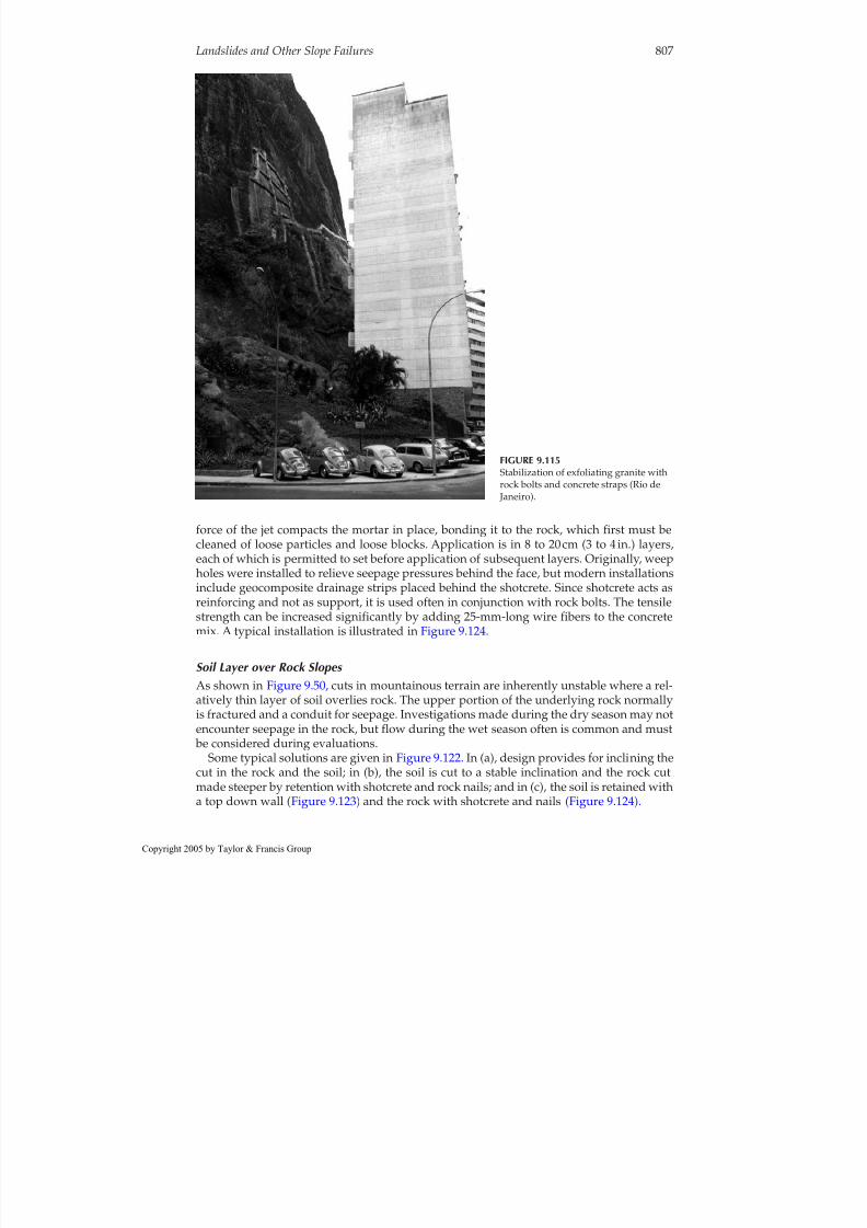
8/12/2019 CH. 9_Geologic Hazard; Landslides and Other Slope Failures
http://slidepdf.com/reader/full/ch-9geologic-hazard-landslides-and-other-slope-failures 111/136
force of the jet compacts the mortar in place, bonding it to the rock, which first must becleaned of loose particles and loose blocks. Application is in 8 to 20cm (3 to 4 in.) layers,each of which is permitted to set before application of subsequent layers. Originally, weepholes were installed to relieve seepage pressures behind the face, but modern installationsinclude geocomposite drainage strips placed behind the shotcrete. Since shotcrete acts asreinforcing and not as support, it is used often in conjunction with rock bolts. The tensilestrength can be increased significantly by adding 25-mm-long wire fibers to the concretemix. A typical installation is illustrated in Figure 9.124.
Soil Layer over Rock Slopes As shown in Figure 9.50, cuts in mountainous terrain are inherently unstable where a rel-atively thin layer of soil overlies rock. The upper portion of the underlying rock normallyis fractured and a conduit for seepage. Investigations made during the dry season may notencounter seepage in the rock, but flow during the wet season often is common and must
be considered during evaluations.Some typical solutions are given in Figure 9.122. In (a), design provides for inclining the
cut in the rock and the soil; in (b), the soil is cut to a stable inclination and the rock cutmade steeper by retention with shotcrete and rock nails; and in (c), the soil is retained witha top down wall ( Figure 9.123) and the rock with shotcrete and nails (Figure 9.124).
Landslides and Other Slope Failures 807
FIGURE 9.115Stabilization of exfoliating granite withrock bolts and concrete straps (Rio de Janeiro).
opyright 2005 by Taylor & Francis Group

8/12/2019 CH. 9_Geologic Hazard; Landslides and Other Slope Failures
http://slidepdf.com/reader/full/ch-9geologic-hazard-landslides-and-other-slope-failures 112/136

8/12/2019 CH. 9_Geologic Hazard; Landslides and Other Slope Failures
http://slidepdf.com/reader/full/ch-9geologic-hazard-landslides-and-other-slope-failures 113/136
Gravity walls provide slope retention by either their weight alone, or their weight com- bined with the weight of a soil mass acting on a portion of their base or by the weight of a composite system. They are free to move at the top thereby mobilizing active earth pres-sure. Included are rock-filled buttresses, gabion walls, crib walls, reinforced earth walls,concrete gravity walls, cantilever walls, and counterfort walls. A series of reinforced earthwalls with a combined height of 100 ft is shown in Figure 9.126. Concrete walls are becom-ing relatively uncommon due to costs, construction time, and the fact that the slope isunsupported during construction.
Gebney and McKittrick (1975) report on a complex system of gravity walls installed tocorrect a debris slide along Highway 39, Los Angeles County, California. The recon-structed roadway was supported on a reinforced earth wall in turn supported by anembankment and a buttress at the toe of the 360-ft-high slope. Horizontal and longitudi-nal drains were installed to relieve hydrostatic pressures in that part of the slide debris
which was not totally removed.Nongravity walls are restrained at the top and not free to move. They include basement
walls, some bridge abutments, and anchored concrete curtain walls. Anchored concrete cur-tain walls, such as the one illustrated in Figure 9.127, can be constructed to substantialheights and have a very high retention capacity. They are constructed from the top down
by excavation of a series of benches into the slope and formation of a section of wall,retained by anchors, in each bench along the slope. Since the slope is thus retained com-pletely during the wall construction, the system is particularly suited to potentially unsta-
ble or unstable slopes. An example of an anchored curtain wall retaining a side-hill fill isshown in Figure 9.128. A variation of the anchored curtain wall consists of anchored pre-
molded concrete panels. The advantage of the system is that the wall conforms readily tothe slope configuration, as shown in Figure 9.129.An alternate “top-down” procedure, common to the United States, is to install anchored
(tiebacks) soldier piles ( Figure 9.123 ). As the excavation proceeds, breasting boards areinstalled in the soldier pile flanges to support the slope.
Landslides and Other Slope Failures 809
FIGURE 9.117Shotcrete applied to retain loose blocks of granite gneiss in cut. Untreated rock exposed in lower right (Rio de Janeiro).
opyright 2005 by Taylor & Francis Group

8/12/2019 CH. 9_Geologic Hazard; Landslides and Other Slope Failures
http://slidepdf.com/reader/full/ch-9geologic-hazard-landslides-and-other-slope-failures 114/136
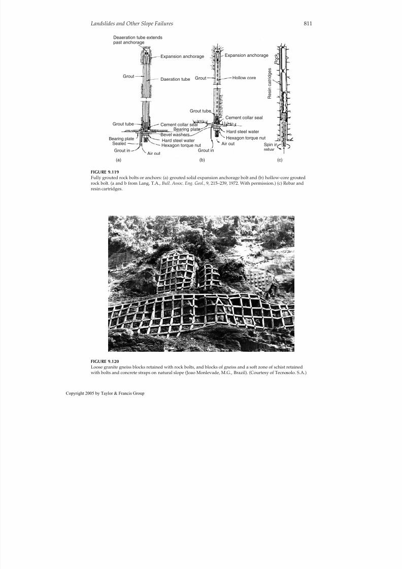
8/12/2019 CH. 9_Geologic Hazard; Landslides and Other Slope Failures
http://slidepdf.com/reader/full/ch-9geologic-hazard-landslides-and-other-slope-failures 115/136
Landslides and Other Slope Failures 811
Deaeration tube extendspast anchorage
Sealed
Expansion anchorage Expansion anchorage
Daeration tube
Cement collar sealCement collar seal
Hard steel water
Hard steel water
Hexagon torque nutHexagon torque nut
Bevel washers
Air out
Air outBearing plate
Bearing plate
Grout in
(a) (b) (c)
Grout in
Grout Grout
Grout tube
Grout tube
Hollow core
Spin inrebar
R e s i n c a t r i d g e s
R o c k
FIGURE 9.119Fully grouted rock bolts or anchors: (a) grouted solid expansion anchorage bolt and (b) hollow-core groutedrock bolt. (a and b from Lang, T.A., Bull. Assoc. Eng. Geol.,9, 215–239, 1972. With permission.) (c) Rebar andresin cartridges.
FIGURE 9.120Loose granite gneiss blocks retained with rock bolts, and blocks of gneiss and a soft zone of schist retainedwith bolts and concrete straps on natural slope (Joao Monlevade, M.G., Brazil). (Courtesy of Tecnosolo. S.A.)
opyright 2005 by Taylor & Francis Group

8/12/2019 CH. 9_Geologic Hazard; Landslides and Other Slope Failures
http://slidepdf.com/reader/full/ch-9geologic-hazard-landslides-and-other-slope-failures 116/136
Earth pressures are determined (magnitude, location, and direction), as influenced bythe slope inclination and height; location and magnitude of surcharge loads; wall type,configuration and dimensions; depth of embedment; magnitude and direction of wallmovement; soil parameters for natural materials and borrowed backfill; and seepageforces.
Stability of gravity walls is evaluated with respect to adequacy against overturning,sliding along the base, foundation bearing failure, and settlement. The slope must be eval-uated with respect to formation of a possible failure surface beneath the wall.
812 Geotechnical Engineering Investigation Handbook, Second Edition
FIGURE 9.121The 60-m-high slope of Figure 9.116 before treatment. The lower portions have been excavated into relativelysound gneiss. The workers (in circle) give the scale. Several large blocks weighing many tons broke looseduring early phases when some scaling of loose blocks was undertaken.
opyright 2005 by Taylor & Francis Group

8/12/2019 CH. 9_Geologic Hazard; Landslides and Other Slope Failures
http://slidepdf.com/reader/full/ch-9geologic-hazard-landslides-and-other-slope-failures 117/136

8/12/2019 CH. 9_Geologic Hazard; Landslides and Other Slope Failures
http://slidepdf.com/reader/full/ch-9geologic-hazard-landslides-and-other-slope-failures 118/136
prone to slope failures, and the type, magnitude, and probability of occurrence. Hazardmaps illustrate the findings.
Individual SlopesIndividual slopes are studied when signs of instability are noted and development is endan-gered, or when new cuts and fills are required for development. Studies should be per-formed in two phases: Phase 1, to establish the overall stability, is a study of the entire slopefrom toe to crest to identify potential or existing failure forms and their failure surfaces, andPhase 2 is a detailed study of the immediate area affected by the proposed cut or fill.
Considerations
Failure Forms and Hazard DegreesEngineers and geologists must be aware of which natural slope conditions are hazardous,which can be analyzed mathematically with some degree of confidence, which are verysensitive to human activities on a potentially catastrophic scale, which can be feasibly con-trolled, and which are to be avoided. They should also be aware that in the present stateof the art there are many limitations in our abilities to predict, analyze, prevent, and con-tain slope failures.
Rotational slides are the forms most commonly anticipated, whereas the occurrence of other forms is often neglected during slope studies. They are generally the least catastrophicof all forms, normally involve a relatively small area, give substantial warning in the formof surface cracking, and usually result in gradual downslope movement during the initialdevelopment stages. Several potential failure forms can exist in a given slope, however.
814 Geotechnical Engineering Investigation Handbook, Second Edition
S h o t c r e t e
f a c i n g
2nd Stage grout
5˚ (typ.)
Nail
Nail
Geocompositedrainage strip
2 " 2 '
A
I6
6"
6 "
3 " 3 " 6 "
A
Mortar packto contain2nd stage
grout
1st Stagegrout
Geocompositedrainage strip Wire mesh
2nd Applicationshotcrete
1st Applicationshotcrete
Shortcrete and nailing detail
¬Section A-A
FIGURE 9.124Retention with shotcrete and nails or bolts in soilor rock.
opyright 2005 by Taylor & Francis Group

8/12/2019 CH. 9_Geologic Hazard; Landslides and Other Slope Failures
http://slidepdf.com/reader/full/ch-9geologic-hazard-landslides-and-other-slope-failures 119/136
Landslides and Other Slope Failures 815
H e a d e r s
Strechers
Selectbackfill
Selectbackfill
Selectbackfill
Backfill
Randombackfill
Compactedselect
fill
Panels
Metal strips
(a)
(d)
(g)
(b)
(e)
(h)
(c)
(f)
(i)
FIGURE 9.125Various types of retaining walls: (a) rock-filled buttress; (b) gabion wall; (c) crib wall; (d) reinforced earth wall;(e) concrete gravity wall; (f) concrete-reinforced semigravity wall; (g) cantilever wall; (h) counterfort wall; (i)anchored curtain wall.
FIGURE 9.126Reinforced earth walls over 100 ft in combined height support roadway fill, I–26, Sams Gap, Tennessee.
opyright 2005 by Taylor & Francis Group

8/12/2019 CH. 9_Geologic Hazard; Landslides and Other Slope Failures
http://slidepdf.com/reader/full/ch-9geologic-hazard-landslides-and-other-slope-failures 120/136
816 Geotechnical Engineering Investigation Handbook, Second Edition
Excavation for steel plant
E l e v a t i o n
( f t )
Fracture Residualsoils
L= 79 °
Fracturedrock,becomingsound
Saprolitehighlydecom-
posed rock
40° slope
2330
2297
2264
2231
2198
2165
2132
Colluvium
Anchored curtainwall
FIGURE 9.127Anchored curtain wall being constructed to a height of 25m and length of 150m, completed to 15 m height(Joao Monlevade, M.G., Brazil). The wall, of maximum thickness of 50 cm, is constructed in sections 1.5 m highfrom the top down, with each section anchored to provide continuous support. Geologic Section is shown inthe inset. (From Hunt, R.E. and Costa Nunes, A.J. da, Civil Engineering, ASCE, 1978, pp. 73–75. Withpermission.)
FIGURE 9.128Anchored concete curtain wall supports fill placed over colluvium. Wall is pile-supported to rock. Slopemovements are occurring downslope to the right but the wall is stable (Highway BR 277, Parana, Brazil).
opyright 2005 by Taylor & Francis Group

8/12/2019 CH. 9_Geologic Hazard; Landslides and Other Slope Failures
http://slidepdf.com/reader/full/ch-9geologic-hazard-landslides-and-other-slope-failures 121/136
Planar slides in mountainous terrain, which usually give warning and develop slowly,can undergo sudden total failure, involving huge volumes and high velocities with disas-trous consequences.
Falls, avalanches, and flows often occur suddenly without warning, move with greatvelocities, and can have disastrous consequences.
Stability FactorsSlope geometry and geology, weather conditions, and seismic activity are the factors influ-encing slope stability, but conditions are frequently transient. Erosion, increased seepageforces, strength deterioration, seismic forces, tectonic activity, as well as human activity, all
undergo changes with time and work to decrease slope stability.Selection of Slope TreatmentsSlope treatments are selected primarily on the basis of judgment and experience, and nor-mally a combination of methods is chosen.
For active slides of large dimensions, consideration should be given chiefly to external andinternal drainage; retaining structures are seldom feasible.
Active slides of small dimensionscan be stabilized by changing their geometry, improvingdrainage, and when a permanent solution is desired, containing them by walls. An alter-native, which is often economically attractive, is to permit the slide to occur and to remove
material continuously from the toe until a stable slope has been achieved naturally. Therisk of total failure, however, must be recognized.Cut slopes are first approached by determining the maximum stable slope angle; if too
much excavation is required or if space does not permit a large cut, alternative methodsemploying retention are considered. It must be noted that side-hill cuts are potentially far
Landslides and Other Slope Failures 817
FIGURE 9.129Stabilization of a slump slide with anchored premolded concrete panels which conform readily to the shape of the slope (Itaorna, R.J., Brazil).
opyright 2005 by Taylor & Francis Group

8/12/2019 CH. 9_Geologic Hazard; Landslides and Other Slope Failures
http://slidepdf.com/reader/full/ch-9geologic-hazard-landslides-and-other-slope-failures 122/136
818 Geotechnical Engineering Investigation Handbook, Second Edition
TABLE 9.10Retaining Wall Characteristics
Wall Type Description Comments
Rook-filled Constructed of nondegradable, Gradation is important to maintain free-
buttress equidimensional rock fragments with at draining characteristicsmid high frictionleast 50% between 30 and 100 cm angle, which combined with weight providesand not more than 10% passing 2-in. sleve retention. Capacity limited by φ of(Royster, (1979). approximately=40° and
space available for construction.Gabion wall Wire baskets, about 50 cm each side, are Free-draining. Retention is obtained from
filled with broken stone about 10 to 15 cm the stone weight and its interlocking andacross. Baskets are then stacked in rows. frictional strength, Typical wall heights
are about 5 to 6 m, but capacity is limited by φ .Crib wall Constructed by forming interconnected Free-draining. Height of single wall is limited
boxes from timber, precast concrete, or to on amount twice the member length.metal members and then filling the boxes Heights are increased by doubling box sectionswith crushed stone or other coarse in depth. High walls arc very sensitive to
granular material. Members are usually transverse differential settlements, and the2 m in length. weakness of cross members precludessupport of high surcharge loads.
Reinforced A compacted backfill of select fill is placed Free-draining and tolerant of differentearth walls as metal strips, called ties, are embedded in settlements, they can have high capacity and
the fill to resist tensile forces. The strips are have been constructed to heights of at leastattached to a thin outer skin of precast 18 m. Relatively large space is required forconcrete panels to retain the face. the wall.
Concrete A m ass of plain concrete. Requires weep holes, free-draining draininggravity backfill, large excavation. Can take no tensilewall stresses and is uneconomical for high walls.
Semigravity Small amount of reinforcing steel is used Requires weep holes, free-draining backfill, andconcrete to reduce concrete volume and provide large excavation. Has been constructed towall capacity for greater heights. heights of 32 m (Kulhawy, 1974).
Cantilever Reinforced concrete with n stem connected Requires weep holes and free-draining backfill;wall to the base. The weight of earth acting on smaller excavation than gravity walls but
the heel is added to the weight of the limited to heights of about 8 m because ofconcrete to provide resistance. inherent weakness of the stem-base
connection.Counterfort A cantilever wall strengthened by the Used for wall heights over 6 to 8 m.
wall addition of counterforts.Buttress wall Similar to counterfort walls except that the As per cantilever and counterfort walls.
vertical braces are placed on the face of the wall rather than on the backfill side.
Anchored A thin wall of reinforced concrete is tied Constructed in the slope from the top down inreinforced- back with anchors to cause the slope and sections to provide continuous retention ofconcrete wall to act as a retaining system. the slope during construction. (All other
curtain wall A variation by Tecnosolo S. A. uses precast walls require an excavation which remainspanels as shown in Figure 9.129. open while the wall is erected.) Retentioncapacity is high and they have been usedto support cuts in residual soils over 25 min height. Drains are installed throughthe wall into the slope. See alsoFigure 9.127 and Figure 9.128 .
Anchored Sheet piles driven or placed in an excavated Seldom used to retain slopes because of itssteel slope and tied back with anchors to tendency to deflect and corrode and its costs,sheet-pile form a flexible wall. although it has been used successfullywall to retain a slope toe in conjunction with other
stabilization methods ( see Figure 9.109) .Bored piles Bored piles have been used occasion to Height is limited by pile capacity in bending.
stabilize failed slopes during initial Site access required for large drill rig unlessstages and cut slopes. holes are hand-excavated.
Root piles Three-dimensional lattice of small- Trade name “Fondedile.” A retaining structurediameter, cast-in-place, reinforced- installed without excavation. Site access forconcrete piles, closely spaced to large equipment required.reinforce the earth mass.
opyright 2005 by Taylor & Francis Group

8/12/2019 CH. 9_Geologic Hazard; Landslides and Other Slope Failures
http://slidepdf.com/reader/full/ch-9geologic-hazard-landslides-and-other-slope-failures 123/136
more dangerous than cuts made in level ground, even with the same cut inclination,depth, and geologic conditions. The significant difference is likely to be seepage condi-tions.
Side-hill fillsmust always be provided with proper drainage, and on steep slopes reten-tion usually is prudent.
Slope Activity MonitoringWhere potentially dangerous conditions exist, monitoring of slope activity with instru-mentation is necessary to provide early warning of impending failures.
Hazard ZoningIn cities and areas where potentially dangerous conditions exist and failures would resultin disastrous consequences, such as on or near high, steep slopes or on sensitive soils nearwater bodies or courses, development should be prohibited by zoning regulations.
Pertinent in this respect is a recent slide in Goteburg, Sweden (ENR, 1977), a country witha long history of slope failures in glaciolacustrine and glaciomarine deposits. Shortly afterheavy rains in early December 1977, a slide occurred taking at least eight lives and carry-ing 67 single-family and row houses into a shallow ravine. Damage was over $7 million.The concluding statement in the article: “Last week’s slide is expected to spark tighter con-trols of construction in questionable areas.”
9.5.2 Regional and Total Slope Studies
Preliminary Phases
Objectives and ScopeThe objectives of the preliminary phases of investigation, for either regional studies or forthe study of a particular area, are to anticipate forms, magnitudes, and incidences of slopefailures.
The study scope includes collection of existing data, generation of new data through ter-rain analysis, field reconnaissance, and evaluation.
Existing Data CollectionRegional data to be collected include: slope failure histories, climatic conditions of precip-
itation and temperature, seismicity, topography (scales of 1:50,000 and 1:10,000), andremote-sensing imagery (scales 1:250,000 to 1:50,000).At the project location, data to be collected include topography (scales of 1:10,000 to
1:2,000, depending upon the area to be covered by the project, and contour intervals of 2to 4 m, or 5 to 10 ft), and remote-sensing imagery (scale of 1:20,000 to 1:6,000). Slope sec-tions are prepared at a 1:1 scale showing the proposed cut or fill in its position relative tothe entire slope.
Landform AnalysisOn a regional basis, landform analysis is performed to identify unstable and potentially
unstable areas, and to establish preliminary conclusions regarding possible failure forms,magnitudes, and incidence of occurrence. A preliminary map is prepared, showing topog-raphy, drainage, active and ancient failures, and geology. The preliminary map is developedinto a hazard map after field reconnaissance. At the project location, more detailed maps areprepared illustrating the items given above, and including points of slope seepage.
Landslides and Other Slope Failures 819
opyright 2005 by Taylor & Francis Group

8/12/2019 CH. 9_Geologic Hazard; Landslides and Other Slope Failures
http://slidepdf.com/reader/full/ch-9geologic-hazard-landslides-and-other-slope-failures 124/136
Field ReconnaissanceThe region or site location is visited and notations are made regarding seepage points,vegetation, creep indications, tension cracks, failure scars, hummocky ground, naturalslope inclinations, and exposed geology. The data collected during landform analysis pro-vide a guide as to the more significant areas to be examined.
Preliminary EvaluationsFrom the data collected, preliminary evaluations are made regarding slope conditions inthe region or project study area, the preliminary engineering geology and hazard maps aremodified, and an exploration program is planned for areas of particular interest.
Explorations
Geophysical Surveys
Seismic refraction profilingis performed to determine the depth to sound rock and the prob-able groundwater table, and is most useful in differentiating between colluvial or residualsoils and the fractured-rock zone. Typical seismic velocities from the weathering profilethat develops in igneous and metamorphic rocks in warm, humid climates are given inTable 2.10 and Figure 9.100. Surveys are made both longitudinal and transverse to theslope. They are particularly valuable on steep slopes with a deep weathering profile wheretest borings are time-consuming and costly.
Resistivity profiling is performed to determine the depth to groundwater and to rock.Profiling is generally only applicable to depths of about 15–30 ft (5–10 m), but very usefulin areas of difficult access. In the soft, sensitive clays of Sweden, the failure surface orpotential failure surface is often located by resistivity measurements since the salt content,and therefore the resistivity, often changes suddenly at the slip surface (Broms, 1975).
Test Boring ProgramTest borings are made to confirm the stratigraphy determined by the geophysical explo-rations, to recover samples of the various materials, and to provide holes for the installa-tion of instrumentation. The depth and number of borings depend on the stratigraphy anduniformity of conditions, but where the slope consists of colluvial or residual soils, boringsshould penetrate to rock. In other conditions, the borings should extend below the depth of any potential failure surface, and always below the depth of cut for an adequate distance.
Sampling should be continuous through the potential or existing rupture zone, and inresidual soils and rock masses care should be taken to identify slickensided surfaces.Groundwater conditions must be defined carefully, although the conditions existing at thetime of investigation are not likely to be those during failure.
In Situ MeasurementsPiezometers yield particularly useful information if in place during the wet season. Inclayey residual profiles, confined water-table conditions can be expected in the weatheredor fractured rock zone near the interface with the residual soils, or beneath colluvium. Apiezometer set into fractured rock under these conditions may disclose artesian pressuresexceeding the hydraulic head given by piezometers set into the overlying soils, even whenthey are saturated (Figure 9.130).
Instrumentation is installed to monitor surface deformations, to measure movementrates, and to detect the rupture zone if the slope is considered to be potentially unstable oris undergoing movement.
820 Geotechnical Engineering Investigation Handbook, Second Edition
opyright 2005 by Taylor & Francis Group

8/12/2019 CH. 9_Geologic Hazard; Landslides and Other Slope Failures
http://slidepdf.com/reader/full/ch-9geologic-hazard-landslides-and-other-slope-failures 125/136
Nuclear probes lowered into boreholes measure density and water content, and have been used to locate a failure surface by monitoring changes in these properties resulting
from material rupture. In a relatively uniform material, the moisture and density logs willshow an abrupt change in the failure zone from the average values (Cotecchia, 1978).
Dating Relict Slide MovementsRadiometric dating of secondary minerals in a ruptured zone or on slickensided surfaces,or of organic strata buried beneath colluvium, provides a basis for estimating the age of previous major movements.
Growth ring counts in trees that are inclined in their lower portion and vertical abovealso provide data for estimating the age of previous major slope movements. The date of the last major movement can be inferred from the younger, vertical-growing segments
(Cotecchia, 1978). Slope failures cause stresses in the tree wood which result in particulartissues (reaction or compressed wood), which are darker and more opaque than normalunstressed wood. On the side toward which the tree leans there is an abrupt change fromthe growth rings of normal wood to those of compression wood. By taking small coresfrom the tree trunk it is possible to count the rings and estimate when the growth changesoccurred and, thus, to date approximately the last major slope movement.
Slope Assessment
Data Presentation
A plan of the slope area is prepared showing contours, drainage paths, seepage emergingfrom the slope, outcrops, tension cracks and other failure scars, and other significantinformation. Sections are prepared at a 1:1 scale illustrating the stratigraphy andgroundwater conditions as determined from the explorations, as well as any relict failuresurfaces.
Landslides and Other Slope Failures 821
S a p r o l i t e z o n e
Fill
4
N a t u r a l w a t e r c o n t e n t
P r o p e r t i e s
S t e n g t h
N a t u r a l d e n s i t y
P l a s t i c i t y5
Legend:(1) shallow slump in colluvium; (2) total failure of cut in residuum caused by very high-seepage pressures
in saprolite; (3) large-scale failure of slope caused by very high-seepage pressures in the fractured rockzone; (4) large rotational failure of fill through residuum;(5) slump failure at fill toe through the colluvium.
C o l l u v i u m
R e s i d u u m
S o u n d r o c k
W e a t h e r e d z o n e
Materialproperties
w (%) PI,LL
p21
2
3
Cut
p3
p1
γ φ c
FIGURE 9.130Schematic of typical section prepared at scale of 1:1 showing tentative cut and fill imposed on 30° slope inresidual soil profile as basis for analysis. Piezometers P1 and P2 show excess water pressures in saprolite andfractured rock compared with saturated zone in residuum at P3. Several possible failure conditions requiringevaluation are shown.
opyright 2005 by Taylor & Francis Group

8/12/2019 CH. 9_Geologic Hazard; Landslides and Other Slope Failures
http://slidepdf.com/reader/full/ch-9geologic-hazard-landslides-and-other-slope-failures 126/136
Evaluations and AnalysesPossible failure forms are predicted and existing failures are delineated as falls, slides, ava-lanches, or flows, and the degree of the hazard is judged. Depending upon the degree of risk, the decision is made to avoid the hazard or to eliminate or reduce it. For the cases of falls, avalanches, flows, and failures by lateral spreading, the decision is based on experi-ence and judgment. Slides may be evaluated by mathematical analysis, but in recognitionthat movements may develop progressively.
Preliminary analysis of existing or potential failures by sliding includes the selection of potential failure surfaces by geometry in the case of planar slides, or analytically in the caseof rotational slides, or by observation in the case of an existing slide. An evaluation is madeof the safety factor against total failure on the basis of existing topographic conditions, thenunder conditions of the imposed cut or fill. For preliminary studies, shear strengths may beestimated from published data, or measured by laboratory or in situ testing. In the selectionof the strength parameters, consideration is given to field conditions (Table 9.6) as well asto changes that may occur with time (reduction from weathering, leaching, solution). Other
transient conditions also require consideration, especially if the safety factor for the entireslope is low and could go below unity with some environmental change.
9.5.3 Detailed Study of Cut, Fill, or Failure Area
General Detailed study of the area of the proposed cut or fill, or of the failure, is undertaken afterthe stability of the entire slope is assessed. The entire slope is often erroneously neglectedin studies of cuts and side-hill fills, and is particularly important in mountainous terrain.
Explorations Seismic refraction surveys are most useful if rock is anticipated within the cut, and there are
boulders in the soils that make the delineation of bedrock difficult with test and core borings.Test and core borings, and test pits are made to recover samples, including undisturbed
samples, for laboratory testing. In colluvium, residuum, and saprolite, the best samplesare often recovered from test pits, but these are usually limited to depths of 10 to 15 ft (3 –5 m) because of practical excavation considerations.
In situ testing is performed in materials from which undisturbed samples are difficult orimpossible to procure.
Laboratory Testing Laboratory strength testing should duplicate the field conditions of pore-water pressures,drainage, load duration, and strain rate that are likely to exist as a consequence of con-struction operations, and samples should usually be tested in a saturated condition. Itmust be considered that conditions during and at the end of construction (short-term) will
be different than long-term stability conditions. In this regard, the natural ability of theslope to drain during cutting plays a significant role.
Evaluation and Analysis Sections illustrating the proposed cut, fill, or failure imposed on the slope are prepared ata 1:1 scale. The selection of cut slope inclination is based on the engineer’s judgment of sta-
bility and is shown on the section together with the stratigraphy, groundwater conditionsmeasured, and the soil properties as shown in Figure 9.130.
822 Geotechnical Engineering Investigation Handbook, Second Edition
opyright 2005 by Taylor & Francis Group

8/12/2019 CH. 9_Geologic Hazard; Landslides and Other Slope Failures
http://slidepdf.com/reader/full/ch-9geologic-hazard-landslides-and-other-slope-failures 127/136
Analyses are performed to evaluate stable cut angles and sidehill fill stability, and thenecessity for drainage and retention. Consideration must be given to the possibility of anumber of failure forms and locations as shown in Figure 9.130, as well as to changinggroundwater and other environmental conditions.
9.5.4 Case Study
Background A roadway was constructed during the early 1990s beginning on the western coastal plainof Ecuador, crossing over the Andes Mountains, and terminating after 110 km at the cityof Cuenca. Landslides began at numerous locations where the roadway climbed the steepmountain slopes, usually 35° or steeper. The general landform along a portion of theroadway is illustrated on the 3D diagram in Figure 9.131. Slope failures increased signifi-cantly during the El Niño years of 1997 and 1998.
Investigation Initially, investigation included a number of trips along the roadway during which theslope failures were photographed and cataloged. Pairs of aerial photos were examinedstereoscopically. Eventually a helicopter fly-over was made and the roadway continuouslyphotographed. Debris avalanches, occurring on the upslope side of the roadway, were themost common form of slope failure ( Figure 8.6, Figure 9.5, and Figure 9.132) . Over 125 fail-ure locations were identified. The landslide debris was bulldozed from the roadway ontothe downslope side (Figure 9.132) further destabilizing the slopes and contributing to ero-sion and choking of streams downslope (see Section 8.2.2 and Figure 8.8) .
Landslides and Other Slope Failures 823
km 40
k m 4 0
M e t e r s
2 0 0 0
. 0 0
4 0. 0 0
3 5. 0 0
3 0. 0 0
2 5. 0 0
2 0. 0 0
K i l o m e t e r s 1 5
. 0 0
1 0. 0 0
5. 0 0
0. 0 0 2 0
. 0 0 1 5
. 0 0 1 0
. 0 0
5 . 0 0
0 . 0 0
FIGURE 9.131Three-dimensional diagram of a portion of roadway over the Andes Mountains in Ecuador. Sidehill failure atkm 62 is shown in Figure 9.6. Debris avalanche at km 88 shown in Figure 9.132. Large slump slide shown inFigure 9.133.
opyright 2005 by Taylor & Francis Group

8/12/2019 CH. 9_Geologic Hazard; Landslides and Other Slope Failures
http://slidepdf.com/reader/full/ch-9geologic-hazard-landslides-and-other-slope-failures 128/136
Other slope failures included a few large “slump” slides ( Figure 9.133) and numerousfailures on the downslope of the roadway resulting from erosion from discharge of road-
way storm drains (Figure 9.6) .
824 Geotechnical Engineering Investigation Handbook, Second Edition
FIGURE 9.132Debris avalanches, km 83 along roadway in Figure 9.131.
FIGURE 9.133Large slump slide at km 75 located in Figure 9.131. Large tension cracks appeared upslope and the tworoadways in the photo center have dropped several meters.
opyright 2005 by Taylor & Francis Group

8/12/2019 CH. 9_Geologic Hazard; Landslides and Other Slope Failures
http://slidepdf.com/reader/full/ch-9geologic-hazard-landslides-and-other-slope-failures 129/136
Budget limitations required that detailed investigations using seismic refraction surveysand test borings be limited to four of the more critical locations.
Evaluations and Treatments
Debris AvalanchesThe debris avalanches were occurring along 80 km of roadway beginning near the low-lands, where the dominant conditions are relatively soft volcanic rocks with a moderatelythick cover of residual soils, and in places, colluvium. The natural slopes usually wereinclined at about 35° or steeper. Initially, vegetation was removed and roadway cuts wereinclined at 53°, much steeper than the original slopes. Subsequently rainfall and seepageresulted in the residual soils sliding along the fractured rock surface.
Unsupported cuts were made because the large number of cuts would cause supportwith retaining walls to make roadway construction prohibitive. A more stable alternateslope design could have included 10-m-high 45° cuts with benches to result in an overallcut slope inclination of 38°. Construction costs would be increased but roadway slope fail-ures and maintenance costs should be decreased.
In many cases where failure has occurred the residual soil has been removed and theslope is now self-stabilized, although in some cases, there remains potentially unstablematerial upslope of the failure scar. Future failures will be removed from the roadwayand disposed off in designated spoil areas, rather than dumping over the sides of theroadway.
Downslope Roadway DrainsIt was recommended that all roadway drains be relocated so that discharge downslope iswhere erosion will not endanger the roadway. Drainage channels should be lined to pre-vent erosion. The failure shown in Figure 9.6 resulted from storm water discharge erodingthe slope below a shotcreted gabion wall that was supporting the roadway. Storm waterentered the catch basin shown on the upslope side of the roadway and discharged througha pipe exiting on the downslope side. The failure in Figure 9.6 was corrected with the con-struction of an anchored wall and relocating the storm water discharge point.
Large Slump SlideAt km 75 the roadway makes an abrupt switch-back as shown in Figure 9.133. At this loca-tion is a large slump slide evidenced by tension cracks upslope and roadway movement.When first visited during 1999 the portion of the roadway in the middle of the photo(Figure 9.133) had dropped about 2 m; when visited the following year, the roadway haddropped an additional 2 m and was almost impassable. This was considered a priority sitefor remediation.
Explorations with seismic refraction surveys and test borings determined geologic con-ditions to include about 15 m of colluvium overlying 5 to 20 m of fractured rock gradingto hard rock.
Treatments recommended for stabilization included:
1. Surface drains constructed upslope to collect runoff and to discharge away from
the failing area2. Subhorizontal drains installed along the toes of the cut slopes areas shown on thephoto
3. Upslope roadway cut slope to be reshaped with benches and covered with shot-crete
Landslides and Other Slope Failures 825
opyright 2005 by Taylor & Francis Group

8/12/2019 CH. 9_Geologic Hazard; Landslides and Other Slope Failures
http://slidepdf.com/reader/full/ch-9geologic-hazard-landslides-and-other-slope-failures 130/136
4. Shotcrete placed to cover the shallow rock slope between the upper and lowerroadways
5. Low anchored concrete walls to be installed along the toe of the upslope anddownslope side of the roadways
6. The roadway grade is not to be raised as this would add load to the unstablemass
9.5.5 Instrumentation and Monitoring
Purpose Instrumentation is required to monitor changing conditions that may lead to total failurewhere slope movement is occurring and safety factors against sliding are low, or where amajor work would become endangered by a slope failure.
Slope-stability analysis is often far from precise, regardless of the adequacy of the dataavailable, and sometimes the provision for an absolutely safe slope is prohibitively costly.In this case, the engineer may wish to have contingency plans available such as the instal-lation of internal drainage systems or the removal of material from upslope, etc., if theslope shows signs of becoming unstable.
In unstable or moving slopes, instrumentation is installed to locate the failure surfaceand determine pore-water pressures for analysis, and to measure surface and subsurfacemovements, velocities, and accelerations which provide indications of impending failure.In cut slopes, instrumentation monitors movements and changing stress conditions to pro-vide early warning and permit invoking remedial measures when low safety factors areaccepted in design.
Instrumentation Methods Summarized Instrumentation is discussed in detail in Chapter 4 , and for slopes is illustrated in Figure4.41 and Figure 4.42.
Surface movements are monitored by survey nets, tiltmeters (on benches), convergencemeters, surface extensometers, and terrestrial photography. Accuracy ranges from 0.5 to1.0 mm for extensometers, to 30 mm for the geodimeter, and to 300 mm for the theodolite(Blackwell et al., 1975). GPS systems are showing promise for continuously monitoringand recording slope movements.
Subsurface deformations are monitored with inclinometers, deflectometers, shear-stripindicators, steel wire and weights in boreholes, and the acoustical emissions device.Accuracy for extensometers and inclinometers usually ranges from 0.5 to 1.0 mm, but theaccuracy depends considerably on the deformation pattern and in many instances cannot
be considered better than 5 to 10 mm.
Pore-water pressures are monitored with piezometers.All instruments should be monitored periodically and the data plotted as it is obtained toshow changing conditions. Movement accelerations are most significant.
GPS Installations
Mission Peak Landslide, Fremont, CaliforniaOn the Internet during 2003, the USGS reported on a GPS installation to monitor theMission Peak Landslide in Fremont, California. Installed in January 2000, the systemincluded a field station with a GPS antenna, receiver, controller card, and radio modem
826 Geotechnical Engineering Investigation Handbook, Second Edition
opyright 2005 by Taylor & Francis Group

8/12/2019 CH. 9_Geologic Hazard; Landslides and Other Slope Failures
http://slidepdf.com/reader/full/ch-9geologic-hazard-landslides-and-other-slope-failures 131/136
that sent data to the base station which included a radio modem, personal computer con-nected to a phone line or the Internet for graphical output. The massive block at the headof the landslide was found initially to be moving at less than 1cm/week, then acceleratingto 2 cm/week apparently in response to rainfall. At the cessation of seasonal rains itremained moving at the rate of 1 mm/week for a 4-month period from February to June2000. GPS measurements were reported to typically show repeatability ±1 cm horizontallyand ±2 cm vertically.
Lishan Slope, Xian, ChinaOrense (2003) describes the landslide hazard threatening the Huaqing Palace, in Xian,China. Built during the Tang dynasty (618–907), the Palace is located at the foot of theLishan slope that shows visible deformation. The potential failure mass is a large-scalerock slide. Although in an area of earthquake activity, it is believed that subsidence in thevalley from extensive groundwater withdrawal has resulted in activating slope move-ments. Geologic conditions generally consist of a layer of loess overlying gneiss bedrock.A site plan is given in Figure 9.134. The potential failure mass has been divided into threepossible blocks. The dashed line represents the limits of a thick loess deposit that hasalready slid.
Studies were begun in 1991 by the Disaster Prevention Institute of Kyoto University, Japan, and the Xian Municipal Government. An extensive automated monitoring systemwas installed as shown in Figure 9.135. Included in the system were short- and long-spanextensometers (lines A and B, Figure 9.134), total station surveying, GPS survey, boreholeinclinometers, and ground motion seismographs. Data are transmitted periodically toKyoto University via satellite.
Landslides and Other Slope Failures 827
N
A1
C'
0 100 200 mExtensometer line
H u a q u i n g p a l a c e
500 FIGURE 9.134Plan map of the Lishan slope in Chinawith potential landslide blocks andextensometer lines (From Orense, R.P.,Geotechnical Hazards: Nature, Assessmentand Mitigation, University of thePhilippines Press, Ouezon City, 2003.With permission. After Sassa, K. et al.,Proceedings of the International Symposiumon Landslide Hazard Assessment,1–24,Xian, China, 1997.)
opyright 2005 by Taylor & Francis Group

8/12/2019 CH. 9_Geologic Hazard; Landslides and Other Slope Failures
http://slidepdf.com/reader/full/ch-9geologic-hazard-landslides-and-other-slope-failures 132/136
References
Alden, W. C., Landslide and Flood at Gros Ventre, Wyoming, Focus on Environmental Geology, TankR., Ed., Oxford University Press, New York (1973), 1928, pp. 146–153.
Banks, D. C., Study of Clay Shale Slopes, Stability of Rock Slopes, Proceedings of the ASCE, 13thSymposium on Rock Mechanics,Urbana, II, (1971), 1972 pp. 303–328.
Banks, D. C. and Strohn, W. E., Calculation of Rock Slide Velocities, Proceedings of the 3rd InternationalCongress for Rock Mechanics, International Society for Rock Mechanics,Denver, Vol. 118, 1974, pp.839–847.
Barton, N., Progressive Failure of Excavated Rock Slopes, Stability of Rock Slopes, Proceedings of the ASCE 13th Symposium on Rock Mechanics, Urbana, II, 1971, 1972, pp. 139–170.
Binger, W. V., Analytical Studies of Panama Canal Slides,” Proceedings of the 2nd InternationalConference on Soil Mechanics and Foundation Engineering,Rotterdam, Vol. 2, 1948, pp. 54–60.
Bishop, A. W., The use of the slip circle in the stability analysis of earth slopes, Geotechnique, 5, 7–17, 1955.
828 Geotechnical Engineering Investigation Handbook, Second Edition
Automatic monitoringfor
landslide risk preparedness
GPS satellite
GPS receiver
Extensometer
Extensometer
3D-SDM ininvestigation tunnel
Slidingsurface
Boreholeinclinometer
Telecomline
Telecom. vialine or satellite
EDIM mirrortarget
DPRI, Kyoto university
Huaqingpalace
To ta l s ta tiona u toma tic tra cing
Lishan landslideprevention
observatory
Seismogram
Three dimensionalshear displacement
meter (3D-SDM)
Lishan
FIGURE 9.135Monitoring system for the Lishan slope prepared for landslide risk assessment. (From Orense, R.P., Geotechnical Hazards: Nature, Assessment and Mitigation, University of the Philippines Press, Ouezon City, 2003. Withpermission. After Sassa, K. et al., Proceedings of the International Symposium on Landslide Hazard Assessment,1–24,Xian, China, 1997.)
opyright 2005 by Taylor & Francis Group

8/12/2019 CH. 9_Geologic Hazard; Landslides and Other Slope Failures
http://slidepdf.com/reader/full/ch-9geologic-hazard-landslides-and-other-slope-failures 133/136
Bjerrum, L., Progressive Failures in Slopes of Overconsolidated Plastic Clay and Clay Shales,Terzaghi Lectures 1963–1972, ASCE, (1974), 1966, pp. 139-189.
Bierrum, L, Loken, T., Heiberg, S. and Foster, H., A Field Study of Factors Responsible for Quick ClaySlides, Proceedings of the 7th International Conference on Soil Mechanics and FoundationEngineering, Mexico City, 1969, pp. 531–540, Vol. 2.
Blackwell, G., Pow, D., and Klast, L., Slope Monitoring at Brenda Mine, Proceedings of the 10thCanadian Rock Mechanics Symposium,Kingston, Ontario, September 1975, pp. 45–79.Brawner, C. O., Case examples of instability of rock slopes, J. Assoc. Prof. Eng. Brit. Columb., 26, 1975.Broms, B. B., Landslides, Foundation Engineering Handbook , Winterkorn, H. F. and Fang, H.-Y., eds.,
Van Nostrand Reinhold Co., NY., 1975, pp. 373–401, Chap. 11.Broms, B. B. and Boman, P., Lime Columns—A New Foundation Method, Proc. ASCE J. Geotech. Eng.
Div., 105, 539–556, 1979.Chassie, R. G. and Goughnor, R. D., States Intensifying Efforts to Reduce Highway Landslides, Civil
Engineering, ASCE, New York, April, 1976, p. 65.Coleman, J. M., Prior, D. B., and Garrison, L. E., Subaqueous Sediment Instabilities in the Offshore
Mississippi River Delta, Open File Report No. 80.01, Bureau of Land Management, U.S.Department of Interior, 1980.
Cotecchia, V., Systematic Reconnaissance Mapping and Registration of Slope Movements, Int. Assoc.of Eng. Geol., Bull. No. 17, 5–37, 1978.
D’Appolonia, E. D., Alperstein, R. A. and D’Appolonia, D. J., Behavior of a colluvial soil slope, Proc. ASCE J. Soil Mech. Found. Eng. Div. , 93, 447–473, 1967.
Deere, D. U. and Patton, F. D., Slope Stability in Residual Soils, Proceedings of the ASCE 4thPan American Conference on Soil Mechanics Foundation Engineering, San Juan, P R, 1971,pp. 87–170.
Easton. W. H., Earthquakes, Rain and Tides of Portuguese Bend Landslide, California, Bull. Assoc.Eng. Geol., 8, 1971.
Eden, W. J., Fletcher, E. B., and Mitchell, R. J., South Nation River Landslide, 16 May 1971, Can.Geotech. J ., 8, 1971.
Elias, V. and Juran, I., Soil Nailing for Stabilization of Highway Slopes and Excavations, Report No.FHWA-RD-89–198, NTIS Springfield, VA, 1991.ENR, Landslide kills eight, destroys 76 homes, Engineering News Record, Dec. 8, 1977, p.11.Focht, Jr. J. A. and Kraft, Jr. L. M., Progress in marine geotechnical engineering, Proc. ASCE J. Geotech.
Eng. Div., 103, 1097–1118, 1977.Fox, P. P., Geology, Exploration, and Drainage of the Serra Slide, Santos, Brasil, Engineering Geology
Case Histories 1–5, The Geological Society of America, Engineering Geological Divsion, 1964pp. 17–24.
Franklin, J. A. and Dusseault, M. B., Rock Engineering, McGraw-Hill Book Co., New York, 1989,pp. 507–536.
Garga, V. K. and De Campos, T. M. P., A Study of Two Slope Failures in Residual Soils, Proceedings of the 5th Southeast Asian Conference on Soil Engineering,Bangkok, 1977, pp. 189–200.
Gebney, D. S. and McKittrick, D. P., Reinforced Earth: A New Alternative for Earth-RetentionStructures, Civil Engineering, ASCE, 1975.
Guidicini, G. and Iwasa, O. Y., Tentative correlation between rainfall and landslides in a humidtropical environment, Bull. Int. Assoc. Eng. Geol., 13–20, 1977.
Habib, P., Production of gaseous pore pressure during rock slides, J. Int. Soc. Rock Mech., 7, 193,1975.
Hamel, J. V., Geology and slope stability in Western Pennsylvania, Bull. AEG, XVII, 1–26, 1980.Hamel, J. V., The slide at Brilliant Cut, in Stability of Rock Slopes, Proceedings of the ASCE, 13th
Symposium on Rock Mechanics,Urbana, II, (1971), 1972, pp. 487–572.Handy, R. L. and Williams, W. W., Chemical Stabilization of an Active Landslide, Civil Engineering,
ASCE, 1967, pp. 62–65.
Heinz, R. A. In situ Soils Measuring Devices, Civil Engineering, ASCE, October 1975, pp. 62–65.Hoek, E. and Bray, J. W., Rock Slope Engineering, 2nd ed., The Institute of Mining and Metallurgy,London, 1977.
Hunt, R.E., Miller, M., and Bump, V., The Forest City Landslide, Proceedings of the 3rd InternationalConference, Case Histories in Geotechnical Engineering, St. Louis, 1993.
Landslides and Other Slope Failures 829
opyright 2005 by Taylor & Francis Group

8/12/2019 CH. 9_Geologic Hazard; Landslides and Other Slope Failures
http://slidepdf.com/reader/full/ch-9geologic-hazard-landslides-and-other-slope-failures 134/136
Hunt, R. E. and Costa Nunes, A. J. da, Retaining Walls: Taking It from the Top, Civil EngineeringASCE, May 1978, pp. 73–75.
Hunt, R. E. and Santiago, W. B., A fundo critica do engenheiro geologo em estudos de implantaclode ferrovias, Proceedings of the 1st Congress, Brasileiro de Geologia de Engenharia, Rio de Janeiro, Aug., Vol. 1, 1976, pp. 79–98.
Jahns, R. H. and Vonder Linden, C., Space–Time Relationships of Landsliding on the Southerly Sideof Palos Verdes Hills, California, Geology, Seismicity and Environmental Impact, Spec. Pub.Assoc. Engrg. Geol., Los Angeles, 1973, pp. 123–138.
Janbu, N., Slope Stability Computations, in Embankment Dam Engineering, Hirschfield, R. C. andPoulos, S. J., eds., J. Wiley, New York, 1973, pp. 47–86.
Janbu, N., Bjerrum, L., and Kjaernsli, B., Soil Mechanics Applied to Some Engineering Problems,Norwegian Geotechnical Institute, Oslo, Publ. 16, 1956, pp. 5–26.
Jones, F. O., Landslides of Rio de Janeiro and the Serra das Araras Escarpment, Brasil, U.S.Geological Survey Paper No. 697, U.S. Govt. Printing Office, Washington, DC, 1973.
Kiersch, G. A., The Vaiont Reservoir Disaster, Focus on Environmental Geology, Tank, R., Ed., TheOxford University Press (1973), Art. 17, 1965, pp. 153–164.
Krahn, J. and Morgenstern, N. R., Mechanics of the Frank slide, Proc. ASCE Rock Eng. Found. Slopes,309–332, 1976.
Kramer, S.L. and Smith, M.W., Modified newmark model for seismic displacements of complaintslopes, J. Geotec. Geoenviron. Eng.,ASCE, 123, 635–644, 1993.
Kulhawy, F. H., Analysis of a High Gravity Retaining Wall, Proceedings of the ASCE Conference on Analysis and Design in Geotechnical Engineering, Univ. of Texas, Austin, I, 1974, pp. 159–171.
Lambe, T. W. and Whitman, R. V., Soil Mechanics, J. Wiley, New York, 1969.Lang, T. A., Rock reinforcement, Bull. Assoc. Eng. Geol.,IX, 215–239, 1972.Lessing, P., Dean, S.L., and Kulander, B.R., Geological Evaluation of West Virginia Landslides, Bull.
Assoc. Eng. Geolog., XXXI, 191–202, 1994.McDonald, B. and Fletcher, J. E., Avalanche — 3500 Peruvians Perish in Seven Minutes, National
Geographic Magazine, June, 1962.McKown, A.F., Early Warning System, Civil Engineering, ASCE , May, pp. 56–59, 1999.Molnia, B. F., Carlson, P. R., and Bruns, T. R., Large Submarine Slide in Kayak Trough, Gulf of Alaska,
Reviews in Engineering Geology, VII, Landslides, Coates, D. R., Ed., Geologic Society of America,1977, pp.137–148.
Mollard. J. D., Regional landslide types in Canada, Reviews in Engineering Geology, Vol. III, Landslides,Geological Society of America, 1977, pp. 29–56.
Morgenstern, N. R. and Price, V. E., The analysis of the stability of general slip surfaces, inGeotechnique, 15, 79–93, 1965.
Morgenstern, N. R. and Sangrey, D. A., Methods of Stability Analysis, in Landslides: Analysis andControl, Schuster, R. L. and Krizek, R. J., eds., Special. Report 176, National Academy of Sciences, Washington, DC, 1978, pp. 255–172, chap. 7.
NAVFAC, Design Manual, Soil Mechanics, Foundations and Earth Structures , DM-7.1, Naval FacilitiesEngineering Command, Alexandria, VA, March, 1982.
Newmark, N. M., Effects of earthquakes on dams and embankments, Geotechnique,15, London, 1965.Noble, H. L., Residual strengths and landslides in clay and shale, Proc. ASCE J. Soil Mechs. Found.
Eng. Div., 99, 1973.Orense, R.P., Geotechnical Hazards: Nature, Assessment and Mitigation, University of the Philippines
Press, Quezon City, 2003.Palladino, D. J. and Peck, R. B., Slope failures in an over-consolidated clay, Seattle, Washington,
Geotechnique, 22, 563–595, 1972.Patton, F. D. and Hendron, Jr., A. J., General Report on Mass Movements, Proceedings of the 2nd
International Cong. Intl. Assoc. Engrg. Geol., Sao Paulo, 1974, p. V-GR 1.
Peck, R. B., Stability of natural slopes, Proc. ASCE J. Soil Mech. Found. Engrg. Div., 93, 1967.Pierson, L.A., Davis, S.A., and Van Vickle, R., Rockfall Hazard Rating System Implementation Manual,FHWA Report No. OR-EG-90-01, Oregon DOT, Highway Div., Salem, OR, 1990.
Piteau, D. R., Regional Slope-Stability Controls and Engineering Geology of the Fraser Canyon,British Columbia, Reviews in Engineering Geology, Vol. III , Coates, D. R., Ed., Geologic Societyof America, Boulder, CO, 1977, pp. 85–112.
830 Geotechnical Engineering Investigation Handbook, Second Edition
opyright 2005 by Taylor & Francis Group

8/12/2019 CH. 9_Geologic Hazard; Landslides and Other Slope Failures
http://slidepdf.com/reader/full/ch-9geologic-hazard-landslides-and-other-slope-failures 135/136
Richter, C. F., Elementary Seismology, W. H. Freeman and Co., San Francisco, 1958, p. 125.Royster, D. L., Highway landslide problems along the Cumberland Plateau, Tennessee, Bull. Assoc.
Eng. Geol., X, 1973.Royster, D. L., Landslide remedial measures, Bull. Assoc., XVI, 301–352, 1979.Santi, P.M., Crenshaw, B.A., and Elifrits, C.D., Demonstration Projects Using Wick Drains to Stabilize
Landslides, Environ. Eng. Sci. , IX, 339–350, Joint Pub.AEG-GSA, 2003.Sassa, K., Fukuoka, H., Yang, Q.J., and Wang, F.W., Landslide Hazard Assessment in CulturalHeritage, Lishan, Xian, Proceedings International Symposium on Landslide Hazard Assessment,1–24, Xian, China, 1997.
Seed, H. B., A method for earthquake resistant design of earth dams, Proc. ASCE J. Soil Mech. Found.Engrg. Div ., 92, 13–41, 1966.
Seed, H. B. and Wilson, S. D., The Turnagain Heights landslide, Anchorage, Alaska, Proc. ASCE J. Soil Mech. Found. Engrg. Div., 93, 325–353, 1967.
Spencer, E., A method of analusis of the stability of embankments assuming parallel inter-sliceforces, Geotechnique,17, 11–26, 1967.
Spencer, E., Thrust line stability in embankment stability analysis, Geotechnique, 23, 85-100, 1973.Sunset, If hillside slides threaten in Southern California, November is planting action month, Sunset
Mag., November, 1978, pp. 122–126.Tavenas, F., Chagnon, J. Y., and La Rochelle, P., The Saint-Jean-Vianney landslide: observations and
eyewitness accounts, Can. Geotech. J ., 8, 1971.Taylor, D. W., Fundamentals of Soil Mechanics, Wiley, New York, 1948.Terzaghi, K., Theoretical Soil Mechanics, Wiley, New York, 1943.Terzaghi, K., Mechanism of landslides, in Engineering Geology (Berkey Volume), The Geologic Society
of America, pp. 83–123, 1950.Terzaghi, K., Stability of steep slopes on hard, unweathered rock, Geotechnique, 12, 251–270, 1962.Tschebotarioff, G. P., Foundations, Retaining and Earth Structures , McGraw-Hill Book Co., New York,
1973.Vargas, M. and Pichler, E., Residual Soils and Rock Slides in Santos, Brazil, Proceedings of the 4th
International Conference Soil Mechanics Foundation Engineering, Vol. 2, 1957, pp. 394–398.Varnes. D. J., Landslide Types and Processes, Landslides and Engineering Practice, Eckel, E. B., Ed.,
Highway Research Board Spec. Report No. 29, Washington, DC, 1958.Varnes. D. J., Slope Movement Types and Processes, Landslides: analysis and Control, Special Report
No. 176, National Academy of Sciences, Washington. DC, 1978, pp. 11–35, chap. 2.Wartman, J., Bray, J.D., and Seed, R.B., Inclined plane studies of the newmark sliding block proce-
dure, J. Geotec. Geoenviron. Eng., ASCE, 129, 673–684, 2003.Youd, T. L., Major Cause of Earthquake Damage is Ground Failure, Civil Engineering, ASCE, pp.
47–51, 1978.
Further Reading
Barata, F. E., Landslides in the Tropical Region of Rio de Janeiro, Proceedings of the 7th InternationalConference on Soil Mechanics and Foundation Engineering, Mexico City, Vol. No. 2, 1969, pp.507–516.
Coates, D. R., Ed., Landslides, Reviews in Engineering Geology, Vol. III, The Geologic Society of America, Boulder, CA, 1977.
Costa Nunes, A. J. da, Slope Stabilization—Improvements in the Prestressed Anchorages in Rocksand Soils, Proceedings of the 1st International Conference on Rock Mechanics, Lisbon, 1966.
Costa Nunes, A. J. da, Landslides in Soils of Decomposed Rock Due to Intense Rainstorms,Proceedings of the 7th International Conference on Soil Mechanics & Foundation Engineering,Mexico City, 1969.
Costa Nunes, A. J. da, Fonseca, A.M.C.C., and Hunt, R. E., A broad view of landslides in Brasil, inGeology and Mechanics of Rockslides and Avalanches,Voight, B., Ed., Elsevier Scientific Pub. Co.,Amsterdam, 1980.
Landslides and Other Slope Failures 831
opyright 2005 by Taylor & Francis Group

8/12/2019 CH. 9_Geologic Hazard; Landslides and Other Slope Failures
http://slidepdf.com/reader/full/ch-9geologic-hazard-landslides-and-other-slope-failures 136/136
Dunn, J. R. and Banino, G. M., Problems with Lake Albany Clays, Reviews in Engineering Geology, Vol.III, Landslides, the Geologic Society of America, Boulder, CO, 1977, pp. 133–136.
ENR, Italian pile system supports slide in its first major U.S. application, Engineering News-Record,Nov. 24, 1977b, p. 16.
Guidicini, G. and Nieble, C. M., Estabilidade de Taludes Naturais e de Escavacao, Editora Edgard Blucher
Ltda., Sao Paulo, 1976, 170pp.Hunt, Roy E., Geotechnical Engineering Investigation Manual, McGraw-Hill Book Co., New York, 1984.Hunt, R.E. and Deschamps, R.J., Stability of Slopes, in The Civil Engineering Handbook , 2nd ed., Chen,
W. F. and Liew, J. Y. R., Eds., CRC Press, Boca Raton, FL, 2003.Hunt, R. E. and Shea, G. P., Avoiding Landslides on Highways in Mountainous Terrain, Proceedings
of the International Road Federation, IV IRF African Highway Conference,Nairobi, January, 1980.Hutchinson, J. N., Assessment of the effectiveness of corrective measures in relation to geological
conditions and types of slope movement, Bull. Int. Assoc. Eng. Geol., Landslides and OtherMass Movements, 131–155, 1977.
Kalkani, E. C. and Piteau, D. R., Finite element analysis of toppling failure at Hell’s Gate Bluffs,British Columbia, Bull. Assoc. Eng. Geol., XIII, 1976.
Kennedy, B. A., Methods of Monitoring Open Pit Slopes, Stability of Rock Slopes, Proceedings of the ASCE 13th Symposiumon on Rock Mechanics,Urbana, II. (1971), 1972, pp. 537–572.
Kenney, T. C., Pazin, M., and Choi, W. S., Design of horizontal drains for soil slopes, Proc., ASCE J.Geotech. Eng. Div., 103, GT11, 1311–1323, 1977.
Koerner, R. M., Lord, Jr., A. E., and McCabe, W. M., Acoustic emission monitoring soil stability, Proc., ASCE J. Geotech. Eng.Div., 104, 571–582, 1978.
La Rochelle, P., Regional geology and landslides in the marine clay deposits of eastern Canada, Can.Geotech. J ., 8, 1970.
Lo, K. Y. and Lee, C. F., Analysis of Progressive Failure in Clay Slopes, Proceedings of the 8th InternationalConference, Soil Mechanics, Foundation Engineering, Moscow, Vol. 1, 1973, pp. 251–258.
Pinckney, C. J., Streiff, D., and Artim, E., The influence of bedding-plane faults in sedimentary for-mations on landslide occurrence western San Diego County, California, Bull. Assoc. Eng. Geol.,
Spring, XVI, 289–300, 1979.Piteau, D. R. and Peckover, F. L., Engineering of Rock Slopes, in Landslides: Analysis and Control,
Schuster and Krizek , Eds., Special Report No. 176, National Academy of Sciences, Washington,DC, 1978, pp. 192–227.
832 Geotechnical Engineering Investigation Handbook, Second Edition