ch-fc march 2007 tech bulletins folder/ch-tb-fc... · 6 model feeds gpm 10 15 20 25 30 40 50 60 mbh...
TRANSCRIPT

CH-FCMarch 2007
(Replaces CH-B-63A, 05/98)
Direct DriveFluid CoolersTechnical Guide
Models WGS and HFS
2
Table of Contents
Overview . . . . . . . . . . . . . . . . . . . . . . . . . . . . . . . . . . . . . . . . . . . . . . . . . . . . . . . . . . . . . . . . . . . . 3Direct-Drive Design Features . . . . . . . . . . . . . . . . . . . . . . . . . . . . . . . . . . . . . . . . . . . . . . . . . . . . . . 3
Selection Procedure . . . . . . . . . . . . . . . . . . . . . . . . . . . . . . . . . . . . . . . . . . . . . . . . . . . . . . . . . . . . 4Selection Formulas . . . . . . . . . . . . . . . . . . . . . . . . . . . . . . . . . . . . . . . . . . . . . . . . . . . . . . . . . . . . . 4
Solutions . . . . . . . . . . . . . . . . . . . . . . . . . . . . . . . . . . . . . . . . . . . . . . . . . . . . . . . . . . . . . . . . . . . . .4Given Conditions . . . . . . . . . . . . . . . . . . . . . . . . . . . . . . . . . . . . . . . . . . . . . . . . . . . . . . . . . . . . . . 4Correction Factors . . . . . . . . . . . . . . . . . . . . . . . . . . . . . . . . . . . . . . . . . . . . . . . . . . . . . . . . . . . . . . 5
Model WGS Capacity Ratings . . . . . . . . . . . . . . . . . . . . . . . . . . . . . . . . . . . . . . . . . . . . . . . . . . . . . . 6Model WGS Specifications and Dimensions . . . . . . . . . . . . . . . . . . . . . . . . . . . . . . . . . . . . . . . . . . . . 7
Model HFS Capacity Ratings . . . . . . . . . . . . . . . . . . . . . . . . . . . . . . . . . . . . . . . . . . . . . . . . . . . . 8-13Model HFS Dimensions . . . . . . . . . . . . . . . . . . . . . . . . . . . . . . . . . . . . . . . . . . . . . . . . . . . . . . . . . 14Model HFS Specifications . . . . . . . . . . . . . . . . . . . . . . . . . . . . . . . . . . . . . . . . . . . . . . . . . . . . . . . .15
© 2007 Heatcraft Refrigeration Products LLC
3
Our engineers have carefully selected and matched components to provide excelled performance, long service life, and a wide range of performance selections. Specifically engineered for outdoor installations, the WGS and HFT fluid coolers are constructed of aluminum and heavy gauge galvanized steel to resist corrosion in all climates.
Fluid coolers are available in a wide range of sizes. Each model is available with several circuit options to ensure the exact fluid cooler for your requirements. Our fluid coolers are designed to reduce the cost of time required for installation. Each unit is completely assembled and tested at the factory. All motor leads are wired to a junction box providing a single point for field wiring.
Direct-Drive Design Features• Cabinets are heavy-duty construction and designed for outdoor
applications; tube sheets and all structural members are fabricated from galvanized steel
• Cabinet panels are fabricated from heavy-gauge aluminum for an attractive appearance and corrosion protection
• Coils are fabricated with corrugated aluminum fins with staggered copper tubes for optimum heat transfer; all units are pressure-tested, dehydrated and pressurized prior to shipment
• Alternate coil constructions are available — copper fins, Pro-Kote™ fins and coated coils
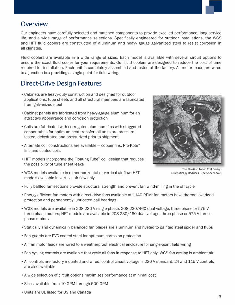
• HFT models incorporate the Floating Tube™ coil design that reduces the possibility of tube sheet leaks
• WGS models available in either horizontal or vertical air flow; HFT models available in vertical air flow only
• Fully baffled fan sections provide structural strength and prevent fan wind-milling in the off cycle
• Energy efficient fan motors with direct-drive fans available at 1140 RPM; fan motors have thermal overload protection and permanently lubricated ball bearings
• WGS models are available in 208-230 V single-phase, 208-230/460 dual-voltage, three-phase or 575 V three-phase motors; HFT models are available in 208-230/460 dual voltage, three-phase or 575 V three-phase motors
• Statically and dynamically balanced fan blades are aluminum and riveted to painted steel spider and hubs
• Fan guards are PVC coated steel for optimum corrosion protection
• All fan motor leads are wired to a weatherproof electrical enclosure for single-point field wiring
• Fan cycling controls are available that cycle all fans in response to HFT only; WGS fan cycling is ambient air
• All controls are factory mounted and wired; control circuit voltage is 230 V standard, 24 and 115 V controls are also available
• A wide selection of circuit options maximizes performance at minimal cost
• Sizes available from 10 GPM through 500 GPM
• Units are UL listed for US and Canada
The Floating Tube™ Coil DesignDramatically Reduces Tube Sheet Leaks
Overview
4
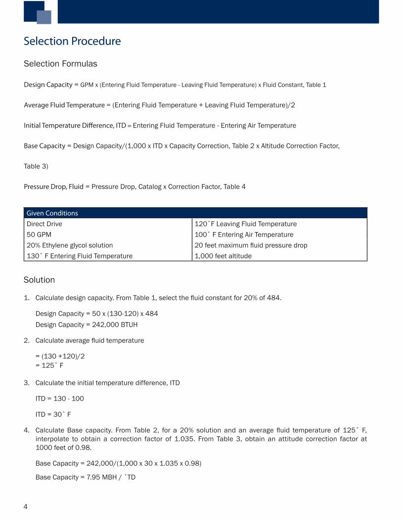
Selection Formulas
Design Capacity = GPM x (Entering Fluid Temperature - Leaving Fluid Temperature) x Fluid Constant, Table 1
Average Fluid Temperature = (Entering Fluid Temperature + Leaving Fluid Temperature)/2
Initial Temperature Difference, ITD = Entering Fluid Temperature - Entering Air Temperature
Base Capacity = Design Capacity/(1,000 x ITD x Capacity Correction, Table 2 x Altitude Correction Factor,
Table 3)
Pressure Drop, Fluid = Pressure Drop, Catalog x Correction Factor, Table 4
Solution
1. Calculate design capacity. From Table 1, select the fluid constant for 20% of 484.
Design Capacity = 50 x (130-120) x 484 Design Capacity = 242,000 BTUH
2. Calculate average fluid temperature
= (130 +120)/2 = 125˚ F 3. Calculate the initial temperature difference, ITD
ITD = 130 - 100
ITD = 30˚ F
4. Calculate Base capacity. From Table 2, for a 20% solution and an average fluid temperature of 125˚ F, interpolate to obtain a correction factor of 1.035. From Table 3, obtain an attitude correction factor at 1000 feet of 0.98.
Base Capacity = 242,000/(1,000 x 30 x 1.035 x 0.98)
Base Capacity = 7.95 MBH / ˚TD
Selection Procedure
Given ConditionsDirect Drive 120˚F Leaving Fluid Temperature50 GPM 100˚ F Entering Air Temperature20% Ethylene glycol solution 20 feet maximum fluid pressure drop130˚ F Entering Fluid Temperature 1,000 feet altitude
5
Percent Glycol
FluidConstant
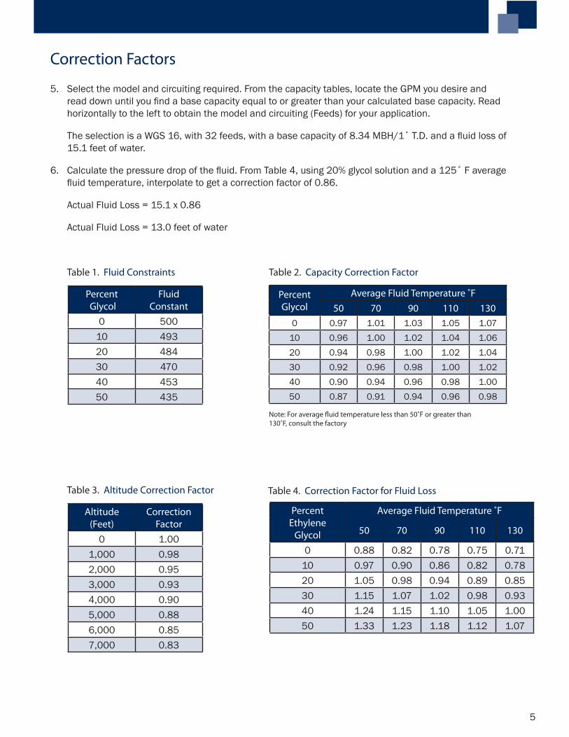
0 50010 49320 48430 47040 45350 435
PercentGlycol
Average Fluid Temperature ˚F50 70 90 110 130
0 0.97 1.01 1.03 1.05 1.0710 0.96 1.00 1.02 1.04 1.0620 0.94 0.98 1.00 1.02 1.0430 0.92 0.96 0.98 1.00 1.0240 0.90 0.94 0.96 0.98 1.0050 0.87 0.91 0.94 0.96 0.98
Table 1. Fluid Constraints
Altitude(Feet)
CorrectionFactor
0 1.001,000 0.982,000 0.953,000 0.934,000 0.905,000 0.886,000 0.857,000 0.83
Table 3. Altitude Correction Factor
Note: For average fluid temperature less than 50˚F or greater than 130˚F, consult the factory
Table 2. Capacity Correction Factor
Table 4. Correction Factor for Fluid Loss
PercentEthylene
Glycol
Average Fluid Temperature ˚F
50 70 90 110 130
0 0.88 0.82 0.78 0.75 0.7110 0.97 0.90 0.86 0.82 0.7820 1.05 0.98 0.94 0.89 0.8530 1.15 1.07 1.02 0.98 0.9340 1.24 1.15 1.10 1.05 1.0050 1.33 1.23 1.18 1.12 1.07
5. Select the model and circuiting required. From the capacity tables, locate the GPM you desire and read down until you find a base capacity equal to or greater than your calculated base capacity. Read horizontally to the left to obtain the model and circuiting (Feeds) for your application.
The selection is a WGS 16, with 32 feeds, with a base capacity of 8.34 MBH/1˚ T.D. and a fluid loss of 15.1 feet of water.
6. Calculate the pressure drop of the fluid. From Table 4, using 20% glycol solution and a 125˚ F average fluid temperature, interpolate to get a correction factor of 0.86.
Actual Fluid Loss = 15.1 x 0.86
Actual Fluid Loss = 13.0 feet of water
Correction Factors
6
Model Feeds GPM
10 15 20 25 30 40 50 60MBH PD* MBH PD* MBH PD* MBH PD* MBH PD* MBH PD* MBH PD* MBH PD*
WGS 049
81216
2.362.23
14.04.7
2.712.582.47
28.79.74.5
2.802.70
16.17.5
2.952.85
24.011.2 2.97 15.5
WGS 080
12162132
3.07 7.4 3.673.55
15.17.0
4.043.923.79
25.211.65.6
4.174.05
17.38.4
4.354.244.02
23.811.53.8
4.494.30
19.26.4
4.664.49
28.59.4 4.62 13.0
WGS 107
121624
3.46 7.5 4.324.16
15.57.1
4.884.734.46
25.711.94.0
5.134.86
17.66.0
5.425.17
24.38.3 5.60 13.8 5.89 20.4 6.10 28.2
WGS 123
121624
3.62 7.5 4.624.45
15.57.1
5.305.124.81
25.711.94.0
5.615.30
17.66.0
5.995.68
24.38.3 6.23 13.8 6.60 20.4 6.88 28.2
WGS 147
121624
3.92 9.4 5.124.96
19.38.9 5.78
5.4914.75.0
6.396.08
21.97.4 6.53 10.2 7.19 16.9 7.64 25.2
WGS 165
122132
4.17 12.4 5.57 25.47.27 9.2 8.44
6.5713.74.4
9.437.09
18.96.1 7.84 10.2 8.34 15.1 8.70 20.9
WGS 211
162448
5.93 12.3 7.226.93
20.56.8 7.90 10.2 8.68 14.0 9.83
8.9723.33.7 9.78 5.5 10.41 7.5
WGS 225
2448
6.99 6.8 7.98 10.2 8.78 14.0 9.969.25
23.33.7 10.14 5.5 10.82 7.5
WGS 248
213264
7.65 12.9 8.818.44
19.16.1
9.739.33
26.38.4 10.66 14.0 11.58
10.6320.83.3
12.2511.33
28.74.5
* PD is glycol fluid loss in feet of water at 130˚F fluid temperature
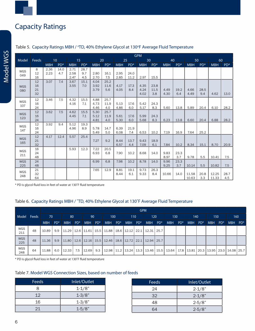
Table 5. Capacity Ratings MBH / oTD, 40% Ethylene Glycol at 130oF Average Fluid Temperature
Model Feeds
GPM
70 80 90 100 110 120 130 140 150 160
MBH PD* MBH PD* MBH PD* MBH PD* MBH PD* MBH PD* MBH PD* MBH PD* MBH PD* MBH PD*
WGS 211 48 10.89 9.9 11.29 12.6 11.61 15.5 11.88 18.6 12.12 22.1 12.31 25.7
WGS 225 48 11.36 9.9 11.80 12.6 12.16 15.5 12.46 18.6 12.72 22.1 12.94 25.7
WGS 248 64 11.88 6.0 12.33 7.5 12.69 9.3 12.98 11.2 13.24 13.3 13.46 15.5 13.64 17.8 13.81 20.3 13.95 23.0 14.08 25.7
* PD is glycol fluid loss in feet of water at 130˚F fluid temperature
Table 6. Capacity Ratings MBH / ˚TD, 40% Ethylene Glycol at 130˚F Average Fluid Temperature
Table 7. Model WGS Connection Sizes, based on number of feeds
Feeds Inlet/Outlet8 1-1/8”
12 1-3/8”16 1-3/8”21 1-5/8”
Feeds Inlet/Outlet24 2-1/8”32 2-1/8”48 2-5/8”64 2-5/8”
Capacity Ratings
Mod
el W
GS
7
Model
Dimensions
(in.) CFMFan Motor Data
Approx.
Net Wt.
(lbs.)A B No. Dia. HP1 FLA1 HP2 FLA2
WGS005WGS008WGS010
39-3/449-3/469-3/4
304060
5,0506,450
10,100
112
242624
1/31/21/3
3.43.96.8
1/31/31/3
2.6/1.32.6/1.35.2/2.6
180260450
WGS012WGS014WGS016
69-3/489-3/489-3/4
608080
12,40013,70012,900
222
262626
1/21/21/2
7.87.87.8
1/31/31/3
5.2/2.65.2/2.65.2/2.6
470510530
WGS021WGS023WGS026
129-3/4129-3/4129-3/4
120120120
20,50019,90019,400
333
262626
1/21/21/2
11.711.711.7
1/31/31/3
7.8/3.97.8/3.97.8/3.9
550580625
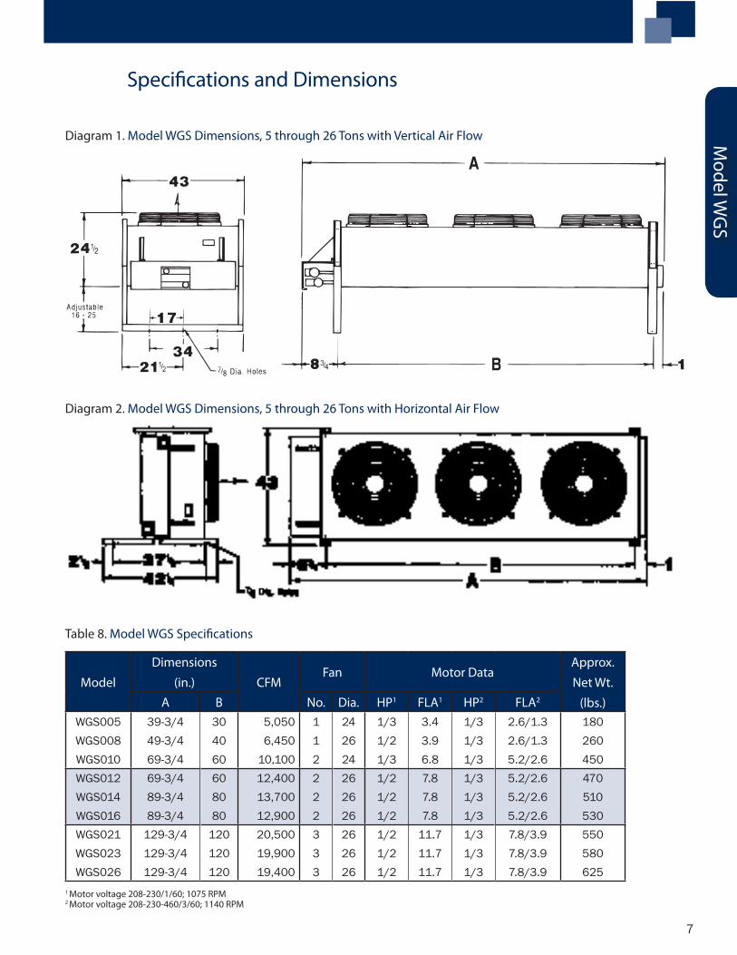
Table 8. Model WGS Specifications
1 Motor voltage 208-230/1/60; 1075 RPM2 Motor voltage 208-230-460/3/60; 1140 RPM
Diagram 1. Model WGS Dimensions, 5 through 26 Tons with Vertical Air Flow
Diagram 2. Model WGS Dimensions, 5 through 26 Tons with Horizontal Air Flow
Model W
GS
Specifications and Dimensions
8
Model Feeds FanConfig.
GPM
20 30 40 50 60 70 80 90 100
MBH PD* MBH PD* MBH PD* MBH PD* MBH PD* MBH PD* MBH PD* MBH PD* MBH PD*
HFS 113
1428 1 x 2 6.4 3.2 8.04 6.5 9.18
8.0810.81.5
10.018.9
16.12.3
10.649.55
22.23.1 10.07 4.1 10.51 5.2 10.87 6.4 11.18 7.8
HFS 133
142142
1 x 27.01 4.8 8.85
8.399.93.2
10.19.60
16.55.3
10.9910.49
24.47.9 11.17
10.0610.81.5
11.710.62
14.22.0
12.1311.08
18.02.6
12.4811.47
22.23.1 11.8 3.8
HFS 149
142142
1 x 27.42 4.8 9.56
9.029.93.2
11.0410.45
16.55.3
12.111.51
24.47.9 12.32
10.9910.81.5
12.9511.64
14.22.0
13.4712.19
18.02.6
13.8912.65
22.23.1 13.05 3.8
HFS 175
182856
1 x 210.2 6.6 11.88
11.211.03.2
13.0812.38
16.34.7
13.9813.29
22.56.5
14.6613.99
29.58.6 14.55
13.1610.81.5
15.0113.67
13.41.9
15.3914.1
16.12.3
HFS 199
142142
1 x 38.19 7.0 10.99
10.5414.34.6
13.0412.52
23.87.7 14.02 11.4 15.19
13.8315.82.3
16.1314.76
20.73.0
16.9015.54
26.23.7 16.19 4.6 16.76 5.6
HFS 223
142142
1 x 311.6211.15
14.34.6
14.0313.43
23.87.7 15.21 11.4 16.61
14.9915.82.3
17.7416.09
20.73.0
18.6617.01
26.23.7 17.79 4.6 18.46 5.6
HFS 226
182856
2 x 211.24 6.6 13.63
12.811.03.2
15.5414.6
16.34.7
17.0816.08
22.56.5
18.3517.31
29.58.6 18.35
16.1710.81.5
19.2417.04
13.41.9
20.0117.81
16.12.3
HFS 247
182856
1 x 311.92 9.5 14.49
13.8515.94.6
16.4515.73
23.56.9 17.22 9.5 18.41 12.4 19.37
17.6915.8 2.3
20.1818.51
19.42.8
20.8519.22
23.43.3
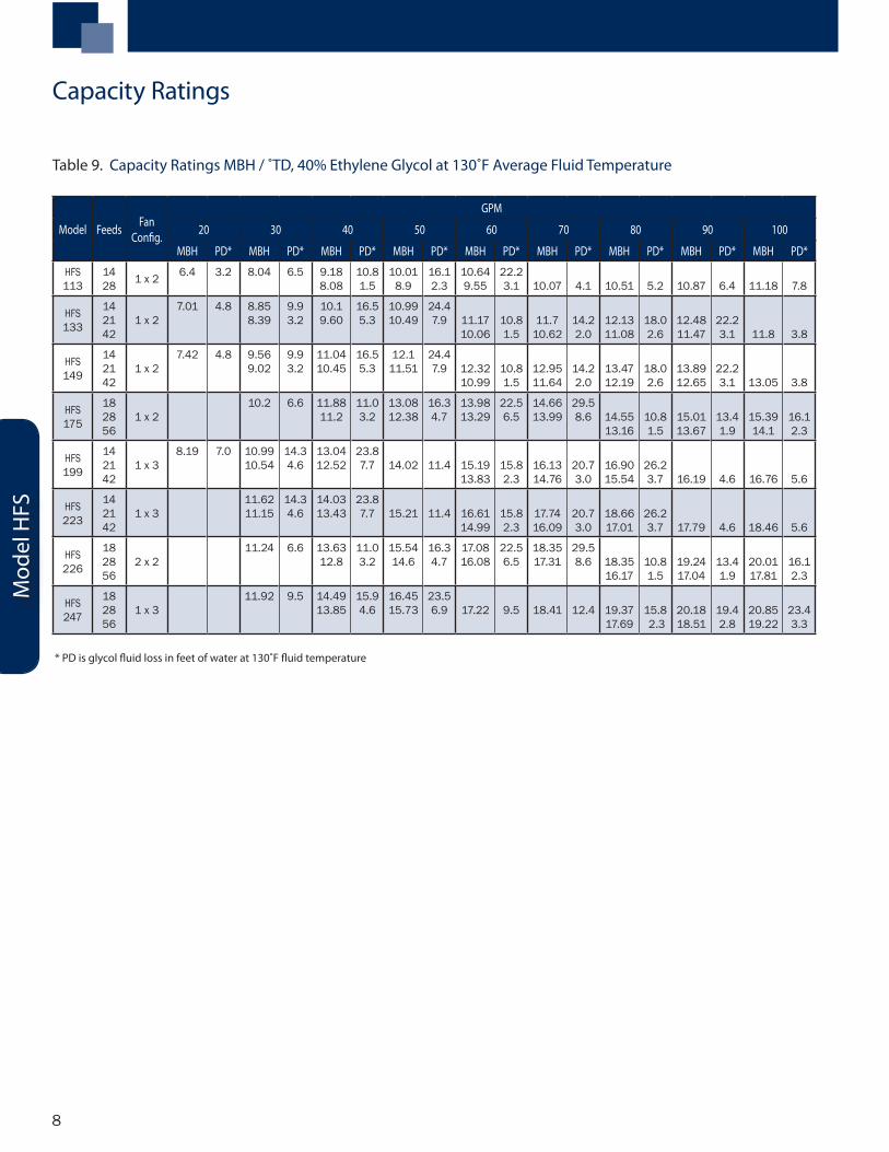
Table 9. Capacity Ratings MBH / ˚TD, 40% Ethylene Glycol at 130˚F Average Fluid Temperature
* PD is glycol fluid loss in feet of water at 130˚F fluid temperature
Mod
el H
FS
Capacity Ratings
9
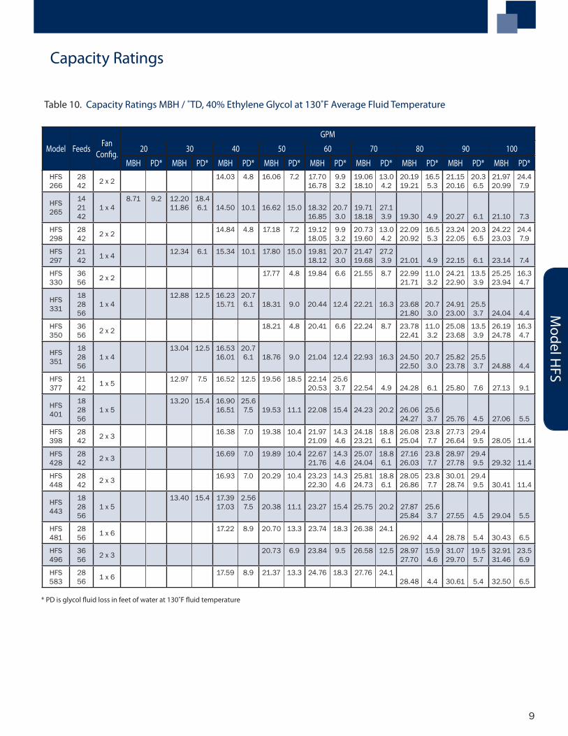
Table 10. Capacity Ratings MBH / ˚TD, 40% Ethylene Glycol at 130˚F Average Fluid Temperature
* PD is glycol fluid loss in feet of water at 130˚F fluid temperature
Model Feeds FanConfig.
GPM
20 30 40 50 60 70 80 90 100
MBH PD* MBH PD* MBH PD* MBH PD* MBH PD* MBH PD* MBH PD* MBH PD* MBH PD*HFS 266
2842 2 x 2 14.03 4.8 16.06 7.2 17.70
16.789.93.2
19.0618.10
13.04.2
20.1919.21
16.55.3
21.1520.16
20.36.5
21.9720.99
24.47.9
HFS 265
142142
1 x 48.71 9.2 12.20
11.8618.46.1 14.50 10.1 16.62 15.0 18.32
16.8520.73.0
19.7118.18
27.13.9 19.30 4.9 20.27 6.1 21.10 7.3
HFS 298
2842 2 x 2 14.84 4.8 17.18 7.2 19.12
18.059.93.2
20.7319.60
13.04.2
22.0920.92
16.55.3
23.2422.05
20.36.5
24.2223.03
24.47.9
HFS 297
2142 1 x 4 12.34 6.1 15.34 10.1 17.80 15.0 19.81
18.1220.73.0
21.4719.68
27.23.9 21.01 4.9 22.15 6.1 23.14 7.4
HFS 330
3656 2 x 2 17.77 4.8 19.84 6.6 21.55 8.7 22.99
21.7111.03.2
24.2122.90
13.53.9
25.2523.94
16.34.7
HFS 331
182856
1 x 412.88 12.5 16.23
15.7120.76.1 18.31 9.0 20.44 12.4 22.21 16.3 23.68
21.8020.73.0
24.9123.00
25.53.7 24.04 4.4
HFS 350
3656 2 x 2 18.21 4.8 20.41 6.6 22.24 8.7 23.78
22.4111.03.2
25.0823.68
13.53.9
26.1924.78
16.34.7
HFS 351
182856
1 x 413.04 12.5 16.53
16.0120.76.1 18.76 9.0 21.04 12.4 22.93 16.3 24.50
22.5020.73.0
25.8223.78
25.53.7 24.88 4.4
HFS 377
2142 1 x 5 12.97 7.5 16.52 12.5 19.56 18.5 22.14
20.5325.63.7 22.54 4.9 24.28 6.1 25.80 7.6 27.13 9.1
HFS 401
182856
1 x 513.20 15.4 16.90
16.5125.67.5 19.53 11.1 22.08 15.4 24.23 20.2 26.06
24.2725.63.7 25.76 4.5 27.06 5.5
HFS 398
2842 2 x 3 16.38 7.0 19.38 10.4 21.97
21.0914.34.6
24.1823.21
18.86.1
26.0825.04
23.87.7
27.7326.64
29.49.5 28.05 11.4
HFS 428
2842 2 x 3 16.69 7.0 19.89 10.4 22.67
21.7614.34.6
25.0724.04
18.86.1
27.1626.03
23.87.7
28.9727.78
29.49.5 29.32 11.4
HFS 448
2842 2 x 3 16.93 7.0 20.29 10.4 23.23
22.3014.34.6
25.8124.73
18.86.1
28.0526.86
23.87.7
30.0128.74
29.49.5 30.41 11.4
HFS 443
182856
1 x 513.40 15.4 17.39
17.032.567.5 20.38 11.1 23.27 15.4 25.75 20.2 27.87
25.8425.63.7 27.55 4.5 29.04 5.5
HFS 481
2856 1 x 6 17.22 8.9 20.70 13.3 23.74 18.3 26.38 24.1
26.92 4.4 28.78 5.4 30.43 6.5
HFS 496
3656 2 x 3 20.73 6.9 23.84 9.5 26.58 12.5 28.97
27.7015.94.6
31.0729.70
19.55.7
32.9131.46
23.56.9
HFS 583
2856 1 x 6 17.59 8.9 21.37 13.3 24.76 18.3 27.76 24.1
28.48 4.4 30.61 5.4 32.50 6.5
Model H
FS
Capacity Ratings
10
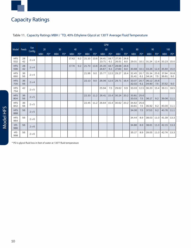
Table 11. Capacity Ratings MBH / ˚TD, 40% Ethylene Glycol at 130˚F Average Fluid Temperature
Model Feeds FanConfig.
GPM
20 30 40 50 60 70 80 90 100
MBH PD* MBH PD* MBH PD* MBH PD* MBH PD* MBH PD* MBH PD* MBH PD* MBH PD*
HFS 532
2842 2 x 4 17.42 9.2 21.10 13.6 24.41
23.7118.76.1
27.3526.51
24.68.0 29.01 10.1 31.24 12.4 33.23 15.0
HFS 596
2842 2 x 4 17.74 9.2 21.70 13.6 25.35
24.6718.76.1
28.6827.83
24.68.0 30.68 10.1 33.26 12.4 35.60 15.0
HFS 660
3656 2 x 4 21.96 9.0 25.77 12.5 29.27 16.4 32.45
31.4120.76.1
35.3434.14
25.67.5
37.9436.61
30.89.0
HFS 700
3656 2 x 4 22.13 9.0 26.06 12.5 29.71 16.4 33.07
32.0220.76.1
36.1234.90
25.67.5 37.52 9.0
HFS 754
42 2 x 5 25.94 7.5 29.62 9.9 33.03 12.5 36.20 15.4 39.11 18.5
HFS 804
3656 2 x 5 22.33 11.2 26.41 15.4 30.24 20.2 33.81
33.0325.67.5 36.17 9.2 39.06 11.1
HFS 842
3656 2 x 5 22.45 11.2 26.64 15.4 30.62 20.2 34.62
33.6125.67.5 36.92 9.2 40.00 11.1
HFS 888
56 2 x 5 34.06 7.5 37.53 9.2 40.76 11.1
HFS 964
56 2 x 6 34.44 8.9 38.03 11.0 41.39 13.3
HFS 986
56 2 x 6 34.86 8.9 38.61 11.0 42.15 13.3
HFS 998
56 2 x 6 35.17 8.9 39.05 11.0 42.74 13.3
* PD is glycol fluid loss in feet of water at 130˚F fluid temperature
Mod
el H
FS
Capacity Ratings
11
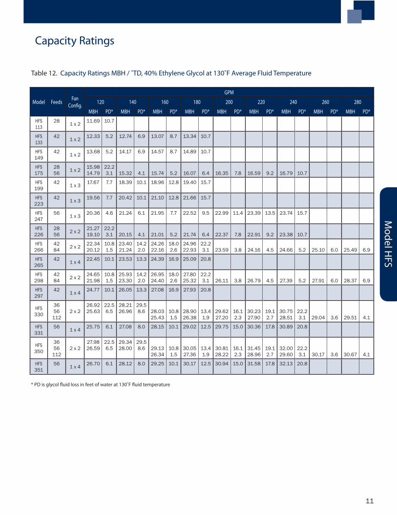
Table 12. Capacity Ratings MBH / ˚TD, 40% Ethylene Glycol at 130˚F Average Fluid Temperature
Model Feeds FanConfig.
GPM
120 140 160 180 200 220 240 260 280
MBH PD* MBH PD* MBH PD* MBH PD* MBH PD* MBH PD* MBH PD* MBH PD* MBH PD*
HFS 113
28 1 x 2 11.69 10.7
HFS 133
42 1 x 2 12.33 5.2 12.74 6.9 13.07 8.7 13.34 10.7
HFS 149
42 1 x 2 13.68 5.2 14.17 6.9 14.57 8.7 14.89 10.7
HFS 175
2856 1 x 2 15.98
14.7922.23.1 15.32 4.1 15.74 5.2 16.07 6.4 16.35 7.8 16.59 9.2 16.79 10.7
HFS 199
42 1 x 3 17.67 7.7 18.39 10.1 18.96 12.8 19.40 15.7
HFS 223
42 1 x 3 19.56 7.7 20.42 10.1 21.10 12.8 21.66 15.7
HFS 247
56 1 x 3 20.36 4.6 21.24 6.1 21.95 7.7 22.52 9.5 22.99 11.4 23.39 13.5 23.74 15.7
HFS 226
2856 2 x 2 21.27
19.1022.23.1 20.15 4.1 21.01 5.2 21.74 6.4 22.37 7.8 22.91 9.2 23.38 10.7
HFS 266
4284 2 x 2 22.34
20.1210.81.5
23.4021.24
14.22.0
24.2622.16
18.02.6
24.9622.93
22.23.1 23.59 3.8 24.16 4.5 24.66 5.2 25.10 6.0 25.49 6.9
HFS 265
42 1 x 4 22.45 10.1 23.53 13.3 24.39 16.9 25.09 20.8
HFS 298
4284 2 x 2 24.65
21.9810.81.5
25.9323.30
14.22.0
26.9524.40
18.02.6
27.8025.32
22.23.1 26.11 3.8 26.79 4.5 27.39 5.2 27.91 6.0 28.37 6.9
HFS 297
42 1 x 4 24.77 10.1 26.05 13.3 27.08 16.9 27.93 20.8
HFS 330
3656
1122 x 2
26.9225.63
22.56.5
28.2126.96
29.58.6 28.03
25.4310.81.5
28.9026.38
13.41.9
29.6227.20
16.12.3
30.2327.90
19.12.7
30.7528.51
22.23.1 29.04 3.6 29.51 4.1
HFS 331
56 1 x 4 25.75 6.1 27.08 8.0 28.15 10.1 29.02 12.5 29.75 15.0 30.36 17.8 30.89 20.8
HFS 350
3656
1122 x 2
27.9826.59
22.56.5
29.3428.00
29.58.6 29.13
26.3410.81.5
30.0527.36
13.41.9
30.8128.22
16.12.3
31.4528.96
19.12.7
32.00 29.60
22.23.1 30.17 3.6 30.67 4.1
HFS 351
56 1 x 4 26.70 6.1 28.12 8.0 29.25 10.1 30.17 12.5 30.94 15.0 31.58 17.8 32.13 20.8
* PD is glycol fluid loss in feet of water at 130˚F fluid temperature
Model H
FS
Capacity Ratings
12
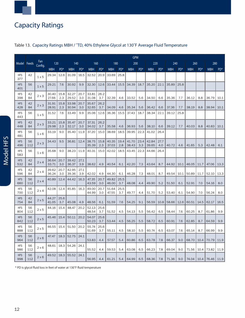
Table 13. Capacity Ratings MBH / ˚TD, 40% Ethylene Glycol at 130˚F Average Fluid Temperature
* PD is glycol fluid loss in feet of water at 130˚F fluid temperature
Model Feeds FanConfig.
GPM
120 140 160 180 200 220 240 260 280
MBH PD* MBH PD* MBH PD* MBH PD* MBH PD* MBH PD* MBH PD* MBH PD* MBH PD*
HFS 377
42 1 x 5 29.34 12.6 31.09 16.5 32.52 20.9 33.69 25.8
HFS 401
56 1 x 5 29.21 7.6 30.92 9.9 32.30 12.6 33.44 15.5 34.39 18.7 35.20 22.1 35.89 25.8
HFS 398
4284 2 x 3 30.40
27.6615.82.3
32.2729.52
20.73.0
33.8131.08
26.23.7 32.39 4.6 33.52 5.6 34.50 6.6 35.36 7.7 36.12 8.8 36.79 10.1
HFS 428
4284 2 x 3 31.91
28.9115.82.3
33.9830.94
20.73.0
35.6732.65
26.23.7 34.09 4.6 35.34 5.6 36.42 6.6 37.36 7.7 38.19 8.8 38.94 10.1
HFS 443
56 1 x 5 31.52 7.6 33.49 9.9 35.06 12.6 36.36 15.5 37.43 18.7 38.34 22.1 39.12 25.8
HFS 448
4284 2 x 3 33.21
29.9815.82.3
35.4732.17
20.73.0
37.3134.02
26.23.7 35.58 4.6 36.93 5.6 38.10 6.6 39.12 7.7 40.03 8.8 40.83 10.1
HFS 481
56 1 x 6 33.19 9.0 35.40 11.9 37.20 15.0 38.69 18.5 39.95 22.3 41.02 26.4
HFS 496
56112 2 x 3 34.43 9.5 36.81 12.4 38.75
35.3915.82.3
40.3537.03
19.42.8
41.7038.43
23.43.3
42.8439.65
27.74.0 40.72 4.6 41.65 5.3 42.48 6.1
HFS 583
56 1 x 6 35.68 9.0 38.23 11.9 40.31 15.0 42.02 18.5 43.45 22.3 44.66 26.4
HFS 532
4284 2 x 4 36.64
33.7120.73.0
39.4236.37
27.13.9 38.62 4.9 40.54 6.1 42.20 7.3 43.64 8.7 44.92 10.1 46.05 11.7 47.06 13.3
HFS 596
4284 2 x 4 39.62
36.2420.73.0
42.9539.36
27.13.9 42.02 4.9 44.30 6.1 46.28 7.3 48.01 8.7 49.54 10.1 50.89 11.7 52.10 13.3
HFS 660
56112 2 x 4 40.89 12.4 44.42 16.3 47.35
43.5920.73.0
49.8246.00
25.53.7 48.08 4.4 49.90 5.2 51.50 6.1 52.91 7.0 54.16 8.0
HFS 700
56112 2 x 4 42.08 12.4 45.85 16.3 49.00
44.9920.73.0
51.6447.55
25.53.7 49.77 4.4 51.70 5.2 53.40 6.1 54.90 7.0 56.24 8.0
HFS 754
4284 2 x 5 44.27
41.0525.63.7 45.08 4.9 48.56 6.1 51.59 7.6 54.25 9.1 56.59 10.8 58.66 12.6 60.51 14.5 62.17 16.5
HFS 804
56112 2 x 5 44.16 15.4 48.47 20.2 52.13
48.5425.63.7 51.52 4.5 54.13 5.5 56.42 6.5 58.44 7.6 60.25 8.7 61.86 9.9
HFS 842
56112 2 x 5 45.46 15.4 50.11 20.2 54.07
50.2325.63.7 53.44 4.5 56.25 5.5 58.72 6.5 60.91 7.6 62.85 8.7 64.59 9.9
HFS 888
56112 2 x 5 46.55 15.4 51.50 20.2 55.74
51.6925.63.7 55.11 4.5 58.10 5.5 60.74 6.5 63.07 7.6 65.14 8.7 66.99 9.9
HFS 964
56112 2 x 6 47.47 18.3 52.75 24.1
53.83 4.4 57.57 5.4 60.86 6.5 63.78 7.8 66.37 9.0 68.70 10.4 70.79 11.9
HFS 986
56112 2 x 6 48.61 18.3 54.26 24.1
55.52 4.4 59.53 5.4 63.08 6.5 66.23 7.8 69.04 9.0 71.56 10.4 73.82 11.9
HFS 998
56112 2 x 6 49.52 18.3 55.52 24.1
56.95 4.4 61.21 5.4 64.99 6.5 68.36 7.8 71.36 9.0 74.04 10.4 76.46 11.9
Mod
el H
FS
Capacity Ratings
13
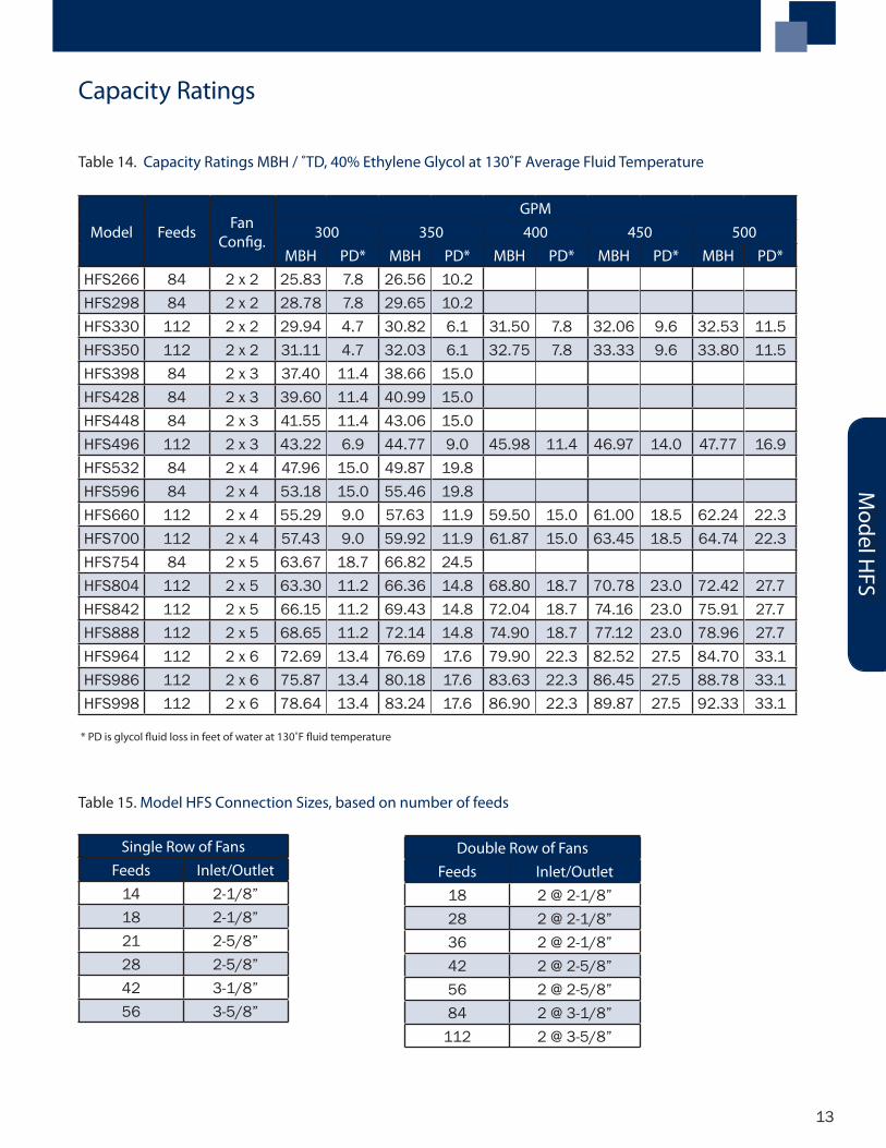
Single Row of FansFeeds Inlet/Outlet
14 2-1/8”18 2-1/8”21 2-5/8”28 2-5/8”42 3-1/8”56 3-5/8”
Double Row of FansFeeds Inlet/Outlet
18 2 @ 2-1/8”28 2 @ 2-1/8”36 2 @ 2-1/8”42 2 @ 2-5/8”56 2 @ 2-5/8”84 2 @ 3-1/8”
112 2 @ 3-5/8”
Table 14. Capacity Ratings MBH / ˚TD, 40% Ethylene Glycol at 130˚F Average Fluid Temperature
Model Feeds FanConfig.
GPM300 350 400 450 500
MBH PD* MBH PD* MBH PD* MBH PD* MBH PD*HFS266 84 2 x 2 25.83 7.8 26.56 10.2HFS298 84 2 x 2 28.78 7.8 29.65 10.2HFS330 112 2 x 2 29.94 4.7 30.82 6.1 31.50 7.8 32.06 9.6 32.53 11.5HFS350 112 2 x 2 31.11 4.7 32.03 6.1 32.75 7.8 33.33 9.6 33.80 11.5HFS398 84 2 x 3 37.40 11.4 38.66 15.0HFS428 84 2 x 3 39.60 11.4 40.99 15.0HFS448 84 2 x 3 41.55 11.4 43.06 15.0HFS496 112 2 x 3 43.22 6.9 44.77 9.0 45.98 11.4 46.97 14.0 47.77 16.9HFS532 84 2 x 4 47.96 15.0 49.87 19.8HFS596 84 2 x 4 53.18 15.0 55.46 19.8HFS660 112 2 x 4 55.29 9.0 57.63 11.9 59.50 15.0 61.00 18.5 62.24 22.3HFS700 112 2 x 4 57.43 9.0 59.92 11.9 61.87 15.0 63.45 18.5 64.74 22.3HFS754 84 2 x 5 63.67 18.7 66.82 24.5HFS804 112 2 x 5 63.30 11.2 66.36 14.8 68.80 18.7 70.78 23.0 72.42 27.7HFS842 112 2 x 5 66.15 11.2 69.43 14.8 72.04 18.7 74.16 23.0 75.91 27.7HFS888 112 2 x 5 68.65 11.2 72.14 14.8 74.90 18.7 77.12 23.0 78.96 27.7HFS964 112 2 x 6 72.69 13.4 76.69 17.6 79.90 22.3 82.52 27.5 84.70 33.1HFS986 112 2 x 6 75.87 13.4 80.18 17.6 83.63 22.3 86.45 27.5 88.78 33.1HFS998 112 2 x 6 78.64 13.4 83.24 17.6 86.90 22.3 89.87 27.5 92.33 33.1
* PD is glycol fluid loss in feet of water at 130˚F fluid temperature
Table 15. Model HFS Connection Sizes, based on number of feeds
Model H
FS
Capacity Ratings
14
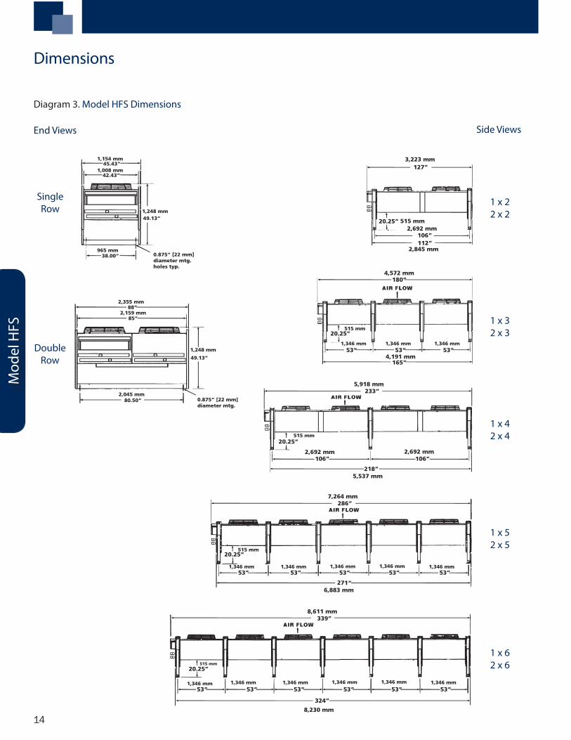
1 x 32 x 3
127”
20.25”
106”112”
180”
20.25”
53” 53” 53”
165”
233”
20.25”
106”
218”
106”
286”
20.25”
53” 53” 53” 53” 53”
271”
339”
20.25”
53” 53” 53” 53” 53” 53”
324”
3,223 mm
515 mm2,692 mm
2,845 mm
515 mm
4,572 mm
1,346 mm 1,346 mm1,346 mm
4,191 mm
1,346 mm 1,346 mm 1,346 mm 1,346 mm 1,346 mm
515 mm
515 mm
1,346 mm 1,346 mm 1,346 mm 1,346 mm 1,346 mm1,346 mm
515 mm
2,692 mm 2,692 mm
5,918 mm
5,537 mm
7,264 mm
6,883 mm
8,611 mm
8,230 mm
1 x 22 x 2
1 x 42 x 4
1 x 52 x 5
1 x 62 x 6
Single Row
Double Row
45.43”
42.43”
38.00”
49.13”
88”
85”
49.13”
80.50”
1,154 mm
1,008 mm
965 mm
1,248 mm
2,355 mm
2,159 mm
0.875” [22 mm] diameter mtg. holes typ.
0.875” [22 mm] diameter mtg. holes typ.
2,045 mm
1,248 mm
Mod
el H
FS
Dimensions
End Views Side Views
Diagram 3. Model HFS Dimensions
15
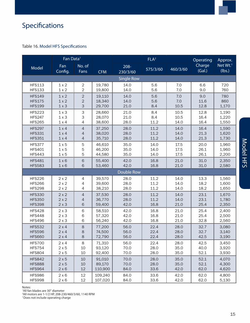
Notes: 1All fan blades are 30" diameter2All motors are 1-1/2 HP, 208-230/460/3/60, 1140 RPM† Does not include operating charge
Model
Fan Data1
CFM
FLA2 OperatingCharge
(Gal.)
Approx.Net Wt.†
(lbs.)Fan
Config.No. ofFans
208-230/3/60 575/3/60 460/3/60
Single RowHFS113HFS133
1 x 21 x 2
22
19,78019,800
14.014.0
5.65.6
7.07.0
6.69.0
720760
HFS149HFS175HFS199
1 x 21 x 21 x 3
223
19,11018,34029,700
14.014.021.0
5.65.68.4
7.07.0
10.5
9.011.612.8
780860
1,170HFS223HFS247HFS265
1 x 31 x 31 x 4
334
28,66028,07038,600
21.021.028.0
8.48.4
11.2
10.510.514.0
12.816.416.4
1,1901,2201,550
HFS297HFS331HFS351
1 x 41 x 41 x 4
444
37,25038,02035,710
28.028.028.0
11.211.211.2
14.014.014.0
16.421.321.3
1,5901,6201,730
HFS377HFS401HFS443
1 x 51 x 51 x 5
555
46,61046,20044,580
35.035.035.0
14.014.014.0
17.517.517.5
20.026.126.1
1,9601,9602,200
HFS481HFS583
1 x 61 x 6
66
55,40053,460
42.042.0
16.816.8
21.021.0
31.031.0
2,3502,580
Double RowHFS226HFS266HFS298
2 x 22 x 22 x 2
444
39,57039,60038,210
28.028.028.0
11.211.211.2
14.014.014.0
13.318.218.2
1,5601,6001,650
HFS330HFS350HFS398
2 x 22 x 22 x 3
446
37,53036,77059,400
28.028.042.0
11.211.216.8
14.014.021.0
23.123.125.4
1,6701,7802,350
HFS428HFS448HFS496
2 x 32 x 32 x 3
666
58,51057,32056,240
42.042.042.0
16.816.816.8
21.021.021.0
25.425.432.8
2,4002,5002,560
HFS532HFS596HFS660
2 x 42 x 42 x 4
888
77,20074,50072,790
56.056.056.0
22.422.422.4
28.028.028.0
32.732.742.5
3,0803,1403,190
HFS700HFS754HFS804
2 x 42 x 52 x 5
81010
71,31093,12092,400
56.070.070.0
22.428.028.0
28.035.035.0
42.540.052.1
3,4503,9203,930
HFS842HFS888HFS964
2 x 52 x 52 x 6
101012
91,01089,170
110,900
70.070.084.0
28.028.033.6
35.035.042.0
52.152.162.0
4,0704,3004,620
HFS986HFS998
2 x 62 x 6
1212
109,240107,020
84.084.0
33.633.6
42.042.0
62.062.0
4,8005,130
Table 16. Model HFS Specifications
Model H
FS
Specifications

A Brand of Heatcraft Refrigeration Products LLC2175 West Park Place Blvd. • Stone Mountain, GA 30087
800.321.1881 • FAX 770.465.5990
www.chandlerref.com
CH-FCTB-0407 | version 000
Since product improvement is a continuing effort, we reserve the right to make changes in specifications without notice.
For more information on Chandler products, contact your Chandler Sales Representative
or visit us at www.chandlerref.com