ch01 smith 140655-7 - media.techtarget.com · ch01_smith_140655-7 4/23/03 5:09 pm page 5. 1.3 pcs...
TRANSCRIPT
Chapter
1Introduction
Since its inception, the mobile wireless industry has undergone tremendouschanges and has seen a plethora of technologies introduced. While the tech-nologies utilized may seem diverse, they all are based on similar concepts andhave similar objectives: the delivery of voice and some data applications. Byunderstanding the similarities and differences between available wireless sys-tems, it is possible to determine how to improve their performance while offer-ing unique services.
In the next few chapters we discuss numerous aspects pertaining to thedesign, deployment, and operation of mobile wireless systems. This chapterbriefly covers some of the key concepts and terminology of mobile wirelesscommunication commonly referred to as cellular communications. The termcellular communications is often interchanged with the terms personal com-munication services (PCS), and third-generation (3G) services, all of which areinterrelated.
The wireless industry continues striving to augment or even replace thewired local loop. This effort has fostered the development of numerous radiotechnologies that operate over a vast range of spectrums from 400 megahertz(MHz) to 40 gigahertz (GHz). Initially wireless access involved delivering ana-log or digitized voice services utilizing a host of modulation techniques. Theprimary focus was on the deployment of radio base stations and then on thedevelopment of adjunct services to retain customers and enhance revenues.But as the Internet and other bandwidth-hungry services and products havebecome more prolific in society, the delivery of data taking precedence over thedelivery of voice services is what is envisioned.
With the proliferation of the Internet protocol (IP) and its permeation intoall aspects of life, both business and personal, the need to support additionalservices has become the driving force for all wired and wireless technologies.Society is being revolutionized through better access to information for thepurposes of making business as well as purchasing decisions. The available
1
Ch01_Smith_140655-7 4/23/03 5:09 PM Page 1

information is so vast that traditional concepts of time and location no longerapply (that is, information is accessible anytime, anyplace). But the revolutionis expected to take several years to fully unfold due to the current bandwidthbottleneck that exists at the “last mile” of any system, both wired and wire-less. Numerous technology platforms that provide the needed bandwidth tofacilitate the information revolution are currently being deployed or are beingconsidered for deployment. The difficulty in the technology platform race is todetermine which transport medium will meet both the current demand modeand any future demand models.
1.1 Communication History
Data communication began with Samuel Morse, who in 1844 invented and pio-neered the telegraph, which used Morse code (consisting of interweaving dotsand dashes) as its method for delivering communication over vast distances.This coding method was so good that it is still used extensively throughout the world today. Wireless data communication became possible thanks to theefforts of Guglielmo Marconi, who is credited with inventing radio.
A very condensed time line of major milestones for the telecommunicationindustry is provided here. There are numerous other milestones of equalimportance for communications, but this list represents shifts in thinking.
1844 Samuel Morse invents the telegraph.
1876 Alexander Bell invents the telephone.
1901 Guglielmo Marconi sends Morse code using a radio.
1931 First U.S. television transmission takes place.
1946 AT&T offers mobile phone service.
1953 First microwave network installed.
1956 Transatlantic cable constructed.
1977 Bell Labs transmits TV signals on optical fibers.
1983 Cellular communication fosters another communications revolution.
Wireless systems have not been in existence long. The first systems wereboth two-way and broadcast. Radio communication at its onset focused pri-marily on voice communications, but with the advent of television it was usedto deliver broadband video coupled with data for instructing the television onhow to display the picture. Microwave communications fostered in the high-speed delivery of data where speeds of 155 megabits per second (Mbit/s) arenow common.
The wired systems have also taken a major leap from just offering voice.Data applications initially involved use of a modem that operated at 300 baud,which then progressed to 1200 baud. Speeds now exceed 1 gigabit per second(Gbit/s) with higher speeds being reached every year as the need for morethroughput increases.
2 Chapter One
Ch01_Smith_140655-7 4/23/03 5:09 PM Page 2
Part of the need for more throughput was the invention of the fax machineand the proliferation of the computer and its numerous technological advances.The Internet has created the need for increased bandwidth so that a host of ser-vices, some still only being dreamed of, can be delivered to subscribers.
The transport platforms for voice and data are becoming similar and requirenot only bandwidth but design and management skills. The communicationsfuture at this time appears to be heading toward using IP as the primary edgeor end-user protocol with other supporting transport protocols like asynchronoustransfer mode (ATM) being used to deliver the information between similar anddissimilar networks.
1.2 Cellular
Cellular communication is one of the most prolific voice communication plat-forms that has been deployed within the last two decades. Cellular systemshave always been able to transport data, and many advancements in differentmodulation formats allow for the delivery of narrowband data. However, cellu-lar systems are unable to provide broadband data services because of band-width limitations. Typical data rates experienced by cellular applications are 9kilobits per second (kbit/s).
Overall, cellular communication is the form of wireless communication thatallows for
� Frequency reuse� Mobility of the subscriber� Handoffs
The cellular concept is employed in many different forms. Typically, whensomeone refers to cellular communication, the reference is to advanced mobilephone system (AMPS) or total-access communications system (TACS) technol-ogy. AMPS operates in the 800-MHz band: 821 to 849 MHz for the base stationreceive and 869 to 894 MHz for the base station transmit. For TACS the fre-quency range is 890 to 915 MHz for the base station receive and 935 to 960MHz for the base station transmit.
Many other technologies also fall within the guise of cellular communica-tion; these include both the domestic U.S. and the international PCS bands. Inaddition the same concept is applied to several technology platforms that arecurrently used in the specialized mobile radio (SMR) band. [IS-136 and inte-grated dispatch enhanced network (iDEN)]. However, cellular communicationreally refers to the AMPS and TACS bands but is sometimes interchangedwith the PCS and SMR bands because of the similarities.
The concept of cellular radio was initially developed by AT&T at their BellLaboratories to provide additional radio capacity for a geographic customerservice area. The initial mobile systems from which cellular evolved were
Introduction 3
Ch01_Smith_140655-7 4/23/03 5:09 PM Page 3

called mobile telephone systems (MTS). Later improvements to these systemsoccurred, and the systems were then referred to as improved mobile telephonesystems (IMTS). One of the main problems with these systems was that amobile call could not be transferred (handed off) from one radio station toanother without loss of the signal. This problem was resolved by reusing theallocated frequencies of the system. With the handoff problem solved, the mar-ket was able to offer higher radio traffic capacity, which allowed for more users,in a geographic service area than with the MTS or IMTS. Cellular radio wasthus a logical progression in the quest to provide additional radio capacity fora geographic area.
The cellular systems in the United States are broken into metropolitanstatistical areas (MSAs) and rural statistical areas (RSAs). Each MSA andRSA has two different cellular operators that offer service. The two cellularoperators are referred to as A-band and B-band systems. The A band is thenonwireline system, and the B band is the wireline system for the MSA orRSA. A brief configuration for a cellular system is shown in Fig. 1.1.
There are numerous types of cellular systems used in the United States andelsewhere. Here is a brief listing of some of the more common ones. All are sim-ilar in network layout in that they have base stations connected to a mobileswitching center (MSC) that in turn connects to the public switched telephonenetwork (PSTN) or postal, telegraph, and telephone (PTT) system.
4 Chapter One
CellularBase Station
Cellular Base Station
CellularBase Station
MSC
PSTN
Figure 1.1 Generic cellular system.
Ch01_Smith_140655-7 4/23/03 5:09 PM Page 4

1. Advanced mobile phone system (AMPS). The cellular standard developedfor use in North America. This type of system operates in the 800-MHz fre-quency band and has also been deployed in South America, Asia, andRussia.
2. Code-division multiple access (CDMA). An alternative digital cellularstandard developed in the United States. It utilizes the IS-95 standard andis implemented as the next generation for cellular systems. The CDMA sys-tem coexists with the current analog system.
3. Digital AMPS (D-AMPS). The digital standard for cellular systems developed for use in the United States, also called North American digitalcellular (NADC). When the existing analog systems needed to be expandedbecause they were growing at a rapid pace, instead of the creation of a newstandard, the AMPS standard was developed into the D-AMPS digital stan-dard. The D-AMPS is designed to coexist with current cellular systems and relies on both the IS-54 and the IS-136 standards.
4. Global system for mobile communications (GSM). The European standardfor digital cellular systems operating in the 900-MHz band. This technolo-gy was developed out of the need for increased service capacity due to theanalog system’s limited growth. This technology offers international roam-ing, high speech quality, increased security, and the ability to developadvanced systems features. It was completed by a consortium of 80 pan-European countries working together to provide integrated cellular sys-tems across different borders and cultures.
5. Nordic mobile telephone (NMT). The cellular standard developed by theNordic countries of Sweden, Denmark, Finland, and Norway in 1981. Thistype of system was designed to operate in the 450- (NMT 450) and 900-MHz(NMT 900) frequency bands. NMT systems have also been deployedthroughout Europe, Asia, and Australia.
6. Total-access communications system (TACS). A cellular standard derivedfrom the AMPS technology. TACS operates in both the 800- and 900-MHzbands. The first system of this kind was implemented in England. Laterthese systems were installed in Europe, China, Hong Kong, Singapore, andthe Middle East. A variation of this standard (JTACS) was implemented inJapan.
7. Integrated dispatch enhanced network (iDEN). The name for an alter-native form of cellular communication which operates in the SMR bandjust adjacent to the cellular frequency band. iDEN is a blend of wirelessinterconnect and dispatch services which makes it very unique comparedto existing cellular and PCS systems. iDEN utilizes a digital radio formatcalled quadrature amplitude modulation (QAM) and is a derivative ofGSM for the rest of the system with the exception of the radio link.
Introduction 5
Ch01_Smith_140655-7 4/23/03 5:09 PM Page 5

1.3 PCS
Personal communication services (PCS) is the next generation of wireless com-munications. It is a general name given to wireless systems that have recentlybeen developed out of the need for more capacity and design flexibility thanthat provided by the initial cellular systems. The similarities between PCS andcellular lie in the mobility of the user of the service. The differences betweenPCS and cellular fall into the applications and spectrum available for PCSoperators to provide to subscribers.
PCS, like its cellular cousin, is another narrowband service which offersmany enhanced data services in conjunction with voice services. It was her-alded in as providing many data services which would enable people to use onecommunication device for all their foreseeable needs. However, because of thebandwidth limitations associated with the PCS systems deployed, the datathroughput remained at 9.6 kbit/s.
Wideband PCS has many promises for offering high-speed data but has notyet been deployed because there are particular problems that must be over-come. The obvious issue is coexistence with the current PCS system. Coupledwith the coexistence problem is the need for more base stations due to reducedsensitivity caused by increased bandwidth. The third major problem thatneeds to be overcome is the offering of subscriber units that can act as dualband units in a vastly diverse PCS marketplace.
Figure 1.1, while labeled as a cellular system, has the same format and lay-out as a PCS system. The chief difference is that the frequency of operation ishigher for PCS and therefore more base stations are required in order to coverthe same geographic area.
The diverse PCS systems that an operator can possibly utilize are listedhere. It is important to note that in several markets the same operator can andhas deployed several types of PCS systems in order to capture market share.
1. DCS1800. A digital standard based upon the GSM technology with theexception that this type of system operates at a higher frequency range,1800 MHz. This technology is intended for use in personal communicationnetwork (PCN) systems. Systems of this type have been installed inGermany and England. (DCS stands for digital cellular system.)
2. PCS1900. A GSM system which is the same as DCS1800 except that itoperates in the PCS frequency band for the United States, 1900 MHz.
3. Personal digital cellular (PDC). A digital cellular standard developed inJapan. PDC-type systems were designed to operate in the 800-MHz and1.5-GHz bands.
4. IS-661. The technology platform that is being promoted by Omnipoint. Itis a spread-spectrum technology that relies on time-division duplexing(TDD).
5. IS-136. The PCS standard that relies on the NADC system except that itoperates in the 1900-MHz band.
6 Chapter One
Ch01_Smith_140655-7 4/23/03 5:09 PM Page 6
6. CDMA. Another popular PCS platform utilizing the same standard as thatfor CDMA in cellular except that it too operates in the 1900-MHz band.
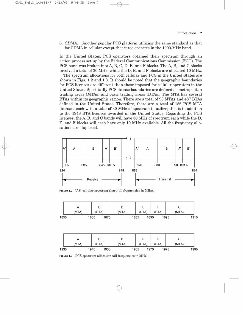
In the United States, PCS operators obtained their spectrum through anaction process set up by the Federal Communications Commission (FCC). ThePCS band was broken into A, B, C, D, E, and F blocks. The A, B, and C blocksinvolved a total of 30 MHz, while the D, E, and F blocks are allocated 10 MHz.
The spectrum allocations for both cellular and PCS in the United States areshown in Figs. 1.2 and 1.3. It should be noted that the geographic boundariesfor PCS licenses are different than those imposed for cellular operators in theUnited States. Specifically PCS license boundaries are defined as metropolitantrading areas (MTAs) and basic trading areas (BTAs). The MTA has severalBTAs within its geographic region. There are a total of 93 MTAs and 487 BTAsdefined in the United States. Therefore, there are a total of 186 PCS MTAlicenses, each with a total of 30 MHz of spectrum to utilize; this is in additionto the 1948 BTA licenses awarded in the United States. Regarding the PCSlicenses, the A, B, and C bands will have 30 MHz of spectrum each while the D,E, and F blocks will each have only 10 MHz available. All the frequency allo-cations are duplexed.
Introduction 7
Receive
824
825 835 845 846.5 870 880 890 891.5
849 869 894
A B A' B'A" A B A' B'A"
Transmit
Figure 1.2 U.S. cellular spectrum chart (all frequencies in MHz).
1850 1865 1870 1885 1890 1895 1910
A
(MTA)
D
(BTA)
B
(MTA)
E
(BTA)
F
(BTA)
C
(MTA)
1930 1945 1950 1965 1970 1975 1990
A
(MTA)
D
(BTA)
B
(MTA)
E
(BTA)
F
(BTA)
C
(MTA)
Figure 1.3 PCS spectrum allocation (all frequencies in MHz).
Ch01_Smith_140655-7 4/23/03 5:09 PM Page 7
1.4 WLL
The wireless local loop (WLL) system utilizes many similar, if not the same, plat-forms as used in the cellular and PCS systems and is primarily focused on voiceservices. The WLL system, however, is different from the cellular or PCS systemsin its application, which is fixed. Being a fixed service it is often referred to as alocal multipoint distribution system (LMDS) or a fixed wireless point-to-multi-point (FWPMP) system. In fact, WLL in many cases is the same as LMDS orFWPMP in its deployment and application. WLL is most applicable in areaswhere local phone service is not available or cost effective. Primarily WLL is asystem that connects a subscriber to the local telephone company (PTSN or PTTsystem) using a radio link as its transport medium instead of copper wires.
There is no specific band that WLL systems occupy or are deployed in. Thesystems can either operate in a dedicated, protected spectrum or in an unli-censed spectrum. Some of the services that fall within the definition of WLLinclude cordless phone systems and fixed cellular systems, as well as a varietyof proprietary systems.
Given the wide choice of system types and the spectrum considerations, thechoice of which combination of system types to use is directly dependent uponthe application and services desired. Some of the additional considerations forchoosing the right technology platform involve the determination of the geo-graphic area needed to be covered, the subscriber density, the usage volume andpatterns expected from the subscribers, and the desired speed of deployment.
Since no one radio protocol and service can do everything, the choice ofwhich system to deploy will be driven by the desired market and applicationsrequired to solve a particular set of issues. Some of the more common types ofWLL systems involve cellular, PCS, cordless telephone (CT-2), and digitalEuropean cordless telecommunication (DECT).
WLL has different implications when deployed in a developed country thanwhen deployed in an emerging country. For a developed country WLL allows foruse of a cordless phone as an extension of the house phone or private branchexchange (PBX), which is an added convenience. However, in an emergingcountry, which has areas without any access to a communication service, theuse of WLL can create profound changes because it is quicker, easier, and lessexpensive to install than a regular landline system.
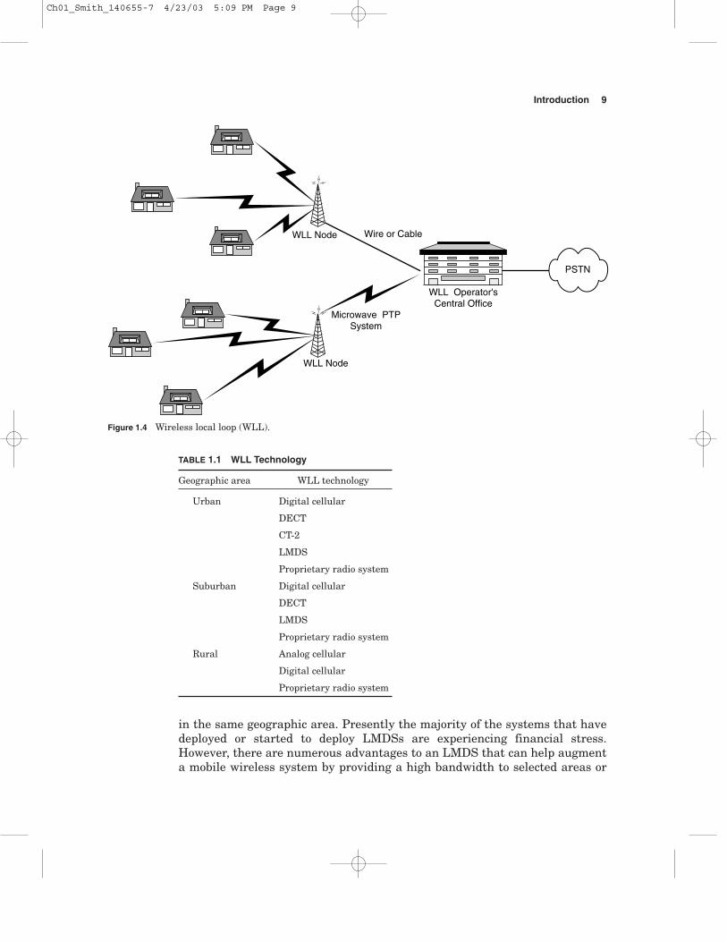
Figure 1.4 represents a typical WLL system. The WLL system has variousnodes that are connected back to a main concentration point. The method forconnecting the nodes to the concentration point can be by radio, wire, cable, ora combination of all three. Table 1.1 is a general representation of differenttechnology platforms that can be used depending on the application involved.This generalization illustrates that there is no single platform or applicationto use when deploying WLL systems.
1.5 LMDS
The local multipoint distribution system (LMDS) is a unique wireless accesssystem whose purpose is to provide broadband access to multiple subscribers
8 Chapter One
Ch01_Smith_140655-7 4/23/03 5:09 PM Page 8
in the same geographic area. Presently the majority of the systems that havedeployed or started to deploy LMDSs are experiencing financial stress.However, there are numerous advantages to an LMDS that can help augmenta mobile wireless system by providing a high bandwidth to selected areas or
Introduction 9
WLL Operator'sCentral Office
WLL Node
WLL Node
Microwave PTPSystem
Wire or Cable
PSTN
Figure 1.4 Wireless local loop (WLL).
TABLE 1.1 WLL Technology
Geographic area WLL technology
Urban Digital cellular
DECT
CT-2
LMDS
Proprietary radio system
Suburban Digital cellular
DECT
LMDS
Proprietary radio system
Rural Analog cellular
Digital cellular
Proprietary radio system
Ch01_Smith_140655-7 4/23/03 5:09 PM Page 9
campus environments coupled with 802.11 (wireless LAN protocol). AdditionallyLMDSs can be used as an effective backhaul method for data traffic.
The LMDS utilizes microwave radio as the fundamental transport mediumand is not really a new technology. It is an adaptation of existing technologyfor a new service implementation that allows multiple users to access thesame radio spectrum. The LMDS is a wireless system that employs cellular-like design and reuse with the exception that there is no handoff. It can beargued that LMDS is in fact another variant to the WLL portfolio describedpreviously and referenced as proprietary radio systems.
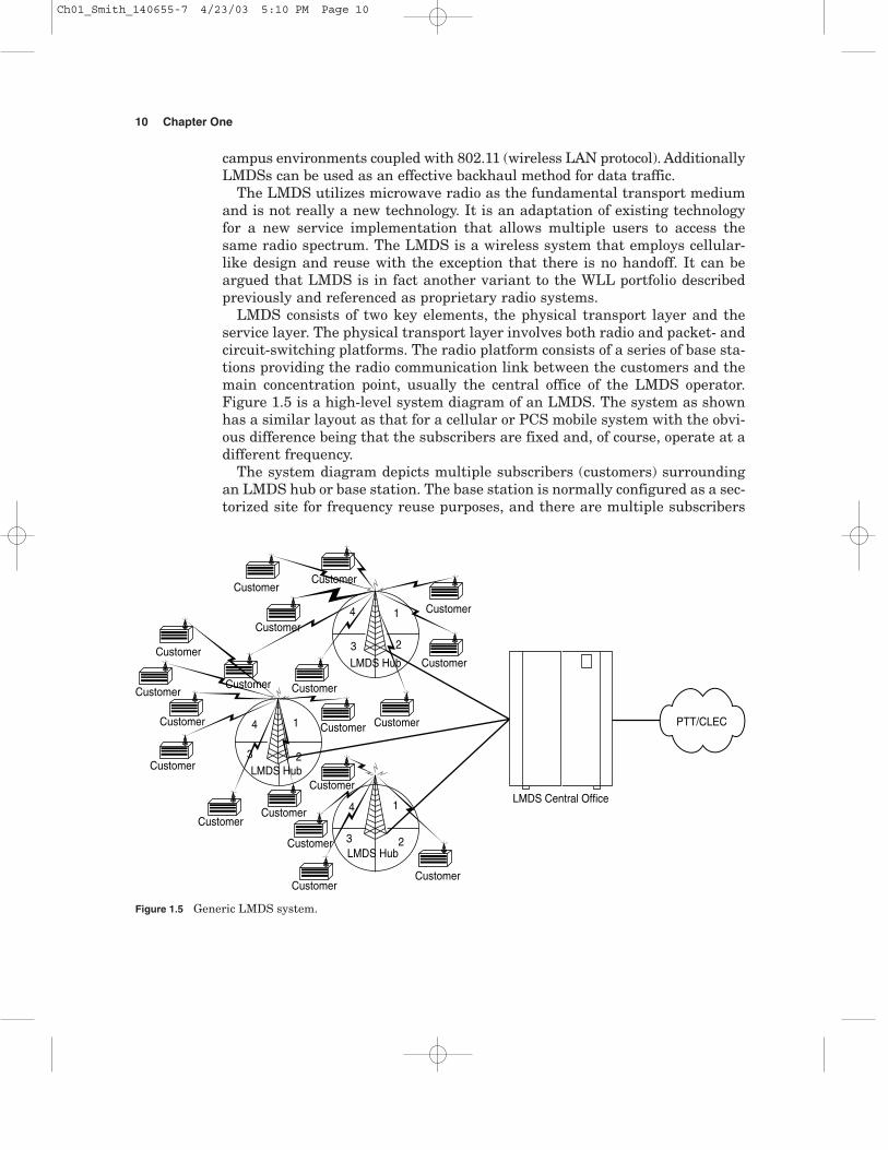
LMDS consists of two key elements, the physical transport layer and theservice layer. The physical transport layer involves both radio and packet- andcircuit-switching platforms. The radio platform consists of a series of base sta-tions providing the radio communication link between the customers and themain concentration point, usually the central office of the LMDS operator.Figure 1.5 is a high-level system diagram of an LMDS. The system as shownhas a similar layout as that for a cellular or PCS mobile system with the obvi-ous difference being that the subscribers are fixed and, of course, operate at adifferent frequency.
The system diagram depicts multiple subscribers (customers) surroundingan LMDS hub or base station. The base station is normally configured as a sec-torized site for frequency reuse purposes, and there are multiple subscribers
10 Chapter One
LMDS Hub
LMDS Central Office
LMDS Hub
LMDS Hub
Customer
Customer
Customer
Customer
Customer
Customer
Customer
1
1
23
4
1
23
4
3
4
2
Customer
Customer
Customer
Customer
Customer
Customer
Customer
Customer
Customer
Customer
Customer
Customer
PTT/CLEC
Figure 1.5 Generic LMDS system.
Ch01_Smith_140655-7 4/23/03 5:10 PM Page 10
assigned to any sector. The amount of channels and the overall frequency planfor the system are driven by the spectrum available in any given market andthe amount of capacity required in any geographic zone.
The LMDS is a point-to-multipoint system where multiple subscribers canaccess the same radio platform utilizing both a multiplexing method as well asqueuing. Specifically a single radio channel may have 12-Mbit/s total through-put, but you might be able to offer 24 Mbit/s or greater for the same channelby allocating it to the entire sector and not to specific customers through over-booking. There, of course, are quality-of-service (QOS) issues and specific ser-vice delivery requirements with any commercial system. However, the conceptis that an LMDS utilizing point-to-multipoint technology can provide vastlygreater bandwidth and services to a larger population than a point-to-pointsystem utilizing the same spectrum can.
Unlike mobile systems an LMDS has several key differences. The first isthat ubiquitous coverage is not required; this is a key advantage. The LMDSif deployed properly can have the operator only provide service where the cus-tomers are actually located thereby maximizing the capital infrastructureeffectiveness and minimizing operating expenses.
The other issue with LMDS relates to the fixed subscriber base that ispotentially there. A primary concept of LMDS delivery is to provide the servicenot to one customer in a sector but to multiple customers. The concept is fur-ther carried to each building where the service is deployed. Specifically, LMDSis best positioned when there are multiple customers that utilize the sameradio equipment, thereby maximizing the capital infrastructure installed atthat location.
A brief example of a building having multiple customers is shown in Fig. 1.6.The simple concept of having multiple customers per geographic location willminimize the cost of acquisition for any customer and at the same time reduceoperating and capital costs. It is important to note that initially the buildingwhere the equipment is to be deployed should be evaluated in order to prop-erly establish its bandwidth potential. In this example, it is assumed thataccess to the wiring closet is achieved for distribution of the services offered.Also, Fig. 1.6 implies that there is LOS (line of sight, that is, no obstructions)with the hub site in order to ensure that the link is of sufficient quality for sta-ble and reliable communication.
LMDS can be a very cost effective alternative for a competitive localexchange carrier (CLEC). With LMDS a CLEC can deploy a wireless systemwithout having to experience the heavy capital requirements of laying downcable or copper to reach customers. The cost effectiveness is born out of the abil-ity to focus the capital infrastructure where the customers are and at the sametime being able to deploy the system in an extremely short period of time.
Some of the services that LMDS can offer customers are listed here. Notethat the service offered cannot have a bandwidth requirement greater thanwhat the radio transport layer can support.
Introduction 11
Ch01_Smith_140655-7 4/23/03 5:10 PM Page 11

Applications
� LAN/wide area network (WAN) [virtual private network (VPN)]� Lease line (T1/E1) replacement (clear and channelized)� Fraction T1/E1 (clear and channelized)� Frame relay� Voice telephony [plain old telephone service (POTS) and enhanced services]� Videoconferencing� Internet connectivity� Web services [e-mail, hosting, virtual Internet service provider (ISP), etc.]� E-commerce� Voice over IP (VoIP)� Fax over IP (FaxIP)� Long-distance and international telephony� Integrated systems digital network (ISDN) [basic rate interference
(BRI) and primary rate interference (PRI)]
12 Chapter One
LMDS SubscriberRadio System
110/66Punchdown Block
MuxingEquipment
Wiring Closet
Router
PBX
PBX
Server
Customer A
Customer B
Customer C
Multiple Customer Location/Dwelling Unit
Figure 1.6 Host location.
Ch01_Smith_140655-7 4/23/03 5:10 PM Page 12

The host of services and perturbations to those just listed make an impres-sive portfolio. Of course, the necessary platforms and connectivity for thenetwork need to be in place in order to ensure that these services can andwill be offered and effectively delivered. It is interesting though that with anLMDS, as with any network, there are on-net and off-net traffic considera-tions. Ideally the traffic should be all on-net, but when the system initiallygoes on-line, most, if not all, the traffic goes off-net and the PTT system oranother CLEC will need to be used almost exclusively to facilitate the deliv-ery of the service.
As with all wireless systems, there are multiple LMDS from which anoperator can choose to deploy. Some of the system architectures to pick fromare frequency-division duplexing (FDD), TDD, time-division multiplexing(TDM)/ATM, ATM, FDD/TDM. Coupled with the transport method, thechoice of modulation scheme as well as frequency planning options must allbe weighed. Additionally another often overlooked aspect is the method foractually delivering service to a customer and the physical and electricaldemarcation location and method.
1.6 MMDS, MDS, ITFS
Multichannel, multipoint distribution systems (MMDSs); instructional televi-sion fixed service (ITFS); and multipoint distribution service (MDS) are all sis-ter bands to LMDS. The combination of MMDS, ITFS, and MDS bands makeup what is referred to as wireless cable.
A total of 33 channels, each 6-MHz wide, make up the MMDS, MDS, andITFS bands collectively. The bands, while currently being referenced together,were all developed for different reasons. However, the bands were originallybroadcast related in that they were one-way oriented. The exception was theITFS channels, which allocate a part of the band for upstream communication.
The MMDS, MDS, ITFS band has numerous subscribers utilizing its ser-vice. However, there has been increased activity in redefining the services theband can and will offer subscribers. The primary focus of the band is towardhigh-speed Internet traffic as compared to video services in conjunction withdata. To make this happen the band has been allocated for two-way communi-cation. But the channels are not paired as is done commonly in other bands.The two technology types now competing for use in this band are the FDD andTDD systems.
The technologies being deployed for the MMDS, MDS, and ITFS band aresimilar to that for the LMDS in that they involve a sectorized cell site whichhas multiple subscriber terminals associated with each channel in every sec-tor. One of the key advantages the MMDS, MDS, and ITFS band has is the fre-quency this band operates within. The bands for operation are 2.15 to 2.162GHz and 2.5 to 2.686 GHz, which do not require strict adherence to line ofsight (LOS) for communication reliability as well as the elimination of rainfade considerations in the link budget.
Introduction 13
Ch01_Smith_140655-7 4/23/03 5:10 PM Page 13
The chief disadvantage with this band is the coordination an operator mustachieve in order to utilize a particular frequency in a geographic area. Thecoordination is exceptionally tricky due to the present existence of MMDS,MDS, and ITFS operators that primarily utilize video as their service offer-ing. The issue arises from both upstream and downstream frequency coordi-nation since existing operators designed their systems based on a broadcastsystem basis.
1.7 Cable Systems
The proliferation of cable modems, primarily in the United States, has broughtbroadband service to many end users who were previously relying on dial-upIP. Cable operators have a unique advantage, as do PTT services, for deliver-ing broadband services to the residential market because they already have apresence in many residential homes.
The common issue facing all broadband providers is the quality of theirunderlying transport layer. The quality of the cable plant itself dictates thedelivery of services that can effectively be offered. The issues with cable plantquality are primarily driven by the number of drops (the wire or cable thatconnects to a house or building, as well as the wire or cable splits within thehouse or building) that are on any cable leg, which directly impacts the ingressnoise problem that limits the ability for the cable plant to provide high-speedtwo-way communication. Since most of the information flow is from the headend to the subscriber, the system does not have to support symmetrical band-width requirements.
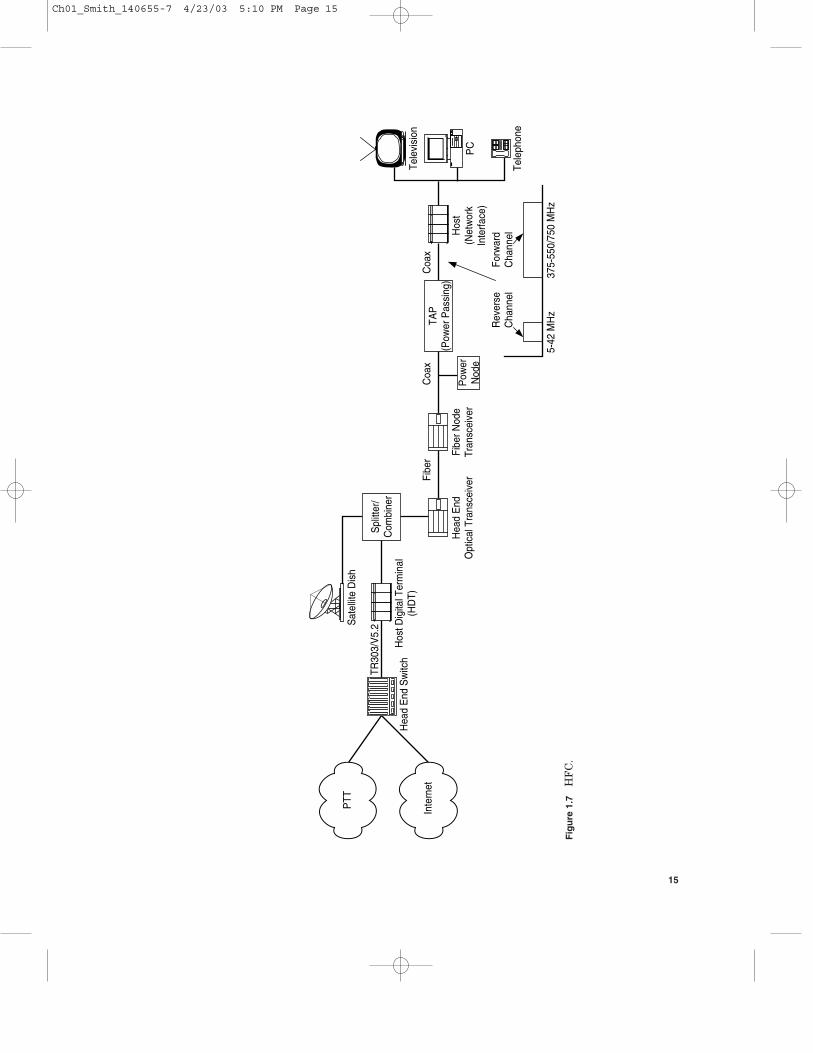
A hybrid fiber/coax (HFC) network is shown in Fig. 1.7, with the enhancementof providing two-way communication for both voice and data, besides the videoservice offering. The primary access method is physical media where the con-nection made to the subscriber at the end of the line is via coaxial cable. Forincreased distance and performance enhancements fiber-optic cables are oftenpart of the cable network’s topology.
Figure 1.8 is an example of a cable operator utilizing wireless access as thelast leg in the access system. The wireless device listed can be a base station ora small remote antenna driver/remote antenna signal processor (RAD/RASP)unit installed on the coaxial cable itself. The figure depicts the potential for acable operator and a wireless operator to utilize each other’s infrastructure todeliver services. It should be noted that PCS is listed in Fig. 1.8 not only formobility telephony but potentially also for better allocation for the PCS C bandauctioned in the United States for delivering last-mile, high-bandwidth services.
1.8 WAP
The wireless application protocol (WAP) is one of the many broadband proto-cols being implemented into the wireless arena for the purpose of increasingmobility by enabling mobile users the ability to surf the Internet. WAP is being
14 Chapter One
Ch01_Smith_140655-7 4/23/03 5:10 PM Page 14
Hea
d E
nd S
witc
hH
ost D
igita
l Ter
min
al(H
DT)
TR30
3/V
5.2
Spl
itter
/C
ombi
ner
Sat
ellit
e D
ish
Hea
d E
ndO
ptic
al T
rans
ceiv
erFi
ber N
ode
Tran
scei
ver
TAP
(Pow
er P
assi
ng)
Pow
erN
ode
Hos
t(N
etw
ork
Inte
rface
)
Tele
visi
on
PC
Tele
phon
e
Coa
xFi
ber
Coa
x
375-
550/
750
MH
z5-
42 M
Hz
Rev
erse
Cha
nnel
Forw
ard
Cha
nnel
PTT
Inte
rnet
Fig
ure
1.7
HF
C.
15
Ch01_Smith_140655-7 4/23/03 5:10 PM Page 15

Hea
d E
ndS
witc
h
Hos
t Dig
ital
Term
inal
(HD
T)
TR30
3/V
5.2
Sat
ellit
eD
ish
Hea
d E
ndO
ptic
al T
rans
ceiv
erFi
ber N
ode
Tran
scei
ver
Hos
t(N
etw
ork
Inte
rface
)
Tele
visi
on
PC
Tele
phon
e
Coa
xFi
ber
Coa
x
375-
550/
750
MH
z5-
42 M
Hz
Rev
erse
Cha
nnel
Forw
ard
Cha
nnel
RA
D/R
AS
P
LMD
S/M
MD
S/U
NII/
ISM
/P
CS
PTT
Inte
rnet
Spl
itter
/C
ombi
ner
Pow
erN
ode
TAP
(Pow
er P
assi
ng)
Fig
ure
1.8
RA
D/R
AS
P.
16
Ch01_Smith_140655-7 4/23/03 5:10 PM Page 16
implemented by numerous mobile equipment vendors since it is meant to pro-vide a universal open standard for wireless phones (i.e., cellular/GSM andPCS) for the purpose of delivering Internet content and other value-added ser-vices. Besides various mobile phones, WAP is also designed to be utilized bypersonal digital assistants (PDAs).
WAP will enable mobile users to surf the Internet in a limited fashion; thatis, they can send and receive e-mails and surf the net in a text-only format(without graphics). For WAP to be utilized by a mobile subscriber the cellularor PCS wireless operator needs to implement WAP in its system as well asensuring that the subscriber units (i.e., the phones) are capable of utilizing theprotocol. WAP is meant to be used by the following cellular/PCS system types:
� GSM-900, GASM-1800, GSM-1900� CDMA IS-95� TDMA IS-136� 3G systems: IMT-2000, universal mobile telecommunications system
(UMTS), wideband-CDMA (W-CDMA), wideband IS-95
WAP is fundamentally different than broadband technologies. While deliver-ing wireless data, it does not have the bandwidth to deliver leased line replace-ment or to support broadband technologies. However, WAP has the potentialto increase the mobility of many subscribers and enable a host of data appli-cations to be delivered for enhanced services to subscribers.
1.9 Bluetooth
Bluetooth is a wireless protocol that operates in the 2.4-GHz industrial-scientific-medical (ISM) band allowing wireless connectivity between mobile phones, PDAs,and other similar devices for the purpose of information exchange. Bluetooth ismeant to replace the infrared telemetry portion on mobile phones and PDAsenabling extended range and flexibility in addition to enhanced services.
Because Bluetooth systems utilize a radio link in the ISM band there areseveral key advantages to this transport protocol. Bluetooth can effectivelyoperate as an extension of a local area network (LAN) or a peer-to-peer LANand provide connectivity between a mobile device and the following otherdevice types:
� Printers� PDAs� Mobile phones� Liquid-crystal display (LCD) projectors� Wireless LAN devices� Notebooks and desktop personal computers
Introduction 17
Ch01_Smith_140655-7 4/23/03 5:10 PM Page 17

One of the key attributes that Bluetooth offers is the range that the system orconnection can operate over. Since Bluetooth operates in the 2.4-GHz ISMband, it has an effective range going from 10 to close to 100 meters (m). Theprotocol does not require line of sight for establishing communication. Its pat-tern is omnidirectional, thereby eliminating orientation issues, and can sup-port both isochronous and asynchronous services paving the way for effectiveuse of TCP/IP communication.
Bluetooth is different than the wireless LAN protocol 802.11 and WAP butagain looks at delivering data connectivity over radio. Bluetooth is also differentbecause of the applications, use of the unlicensed band, and focus on end-userdevices. Bluetooth is meant to be a LAN extension fostering communication con-nection ease for short distances.
1.10 Wireless LAN (802.11)
Wireless LAN (WLAN) is another wireless platform enabling various computersor separate LANs to be connected together into one LAN or WAN. A big advan-tage is that WLAN-enabled devices do not need to be physically connected to anywired outlet, which allows for location flexibility as shown in Fig. 1.9.
18 Chapter One
Router
Wireless LAN
Wireless LAN
Wireless LAN
Wireless LAN
Server
WirelessOperator’s
PDSN
Wireless Operator’sCell Site
Internet
2.5G/3G WirelessSystem
Ethernet
Ethernet
Figure 1.9 WLAN.
Ch01_Smith_140655-7 4/23/03 5:10 PM Page 18
The convergence of WLAN 802.11 with wireless mobility has been describedas the “real killer application.” This means that it will truly allow the sub-scriber to take advantage of all the applications available on the World WideWeb while at the office, home office, or on the road at some unknown location,provided, of course, there is coverage. The issue of security and provisioning tomake this a reality is not a trivial matter if true transparency (requiring nouser intervention) is desired with the intranet of a company by its sales andsupport staff.
There are several protocols that fall into the WLAN arena. Not all of themare compatible, which leaves the possibility of local islands (when the proto-cols cannot communicate with each other unless a device provides translation)being established. The most prevalent WLAN protocol is IEEE 802.11, butBluetooth is also referred to as a WLAN protocol. 802.11 is an Institute ofElectrical and Electronics Engineers (IEEE) specification encompassing sev-eral standards; some of the more prevalent ones are 802.11a, 802.11b (WiFi),and 802.11g.
What is interesting is that 802.11a operates in the 5-GHz, unlicensednational information infrastructure (UNII) band, while 802.11b and 802.11goperate in the 2.4-GHz ISM band along with Bluetooth. 802.11g specifically ismeant to increase the data rate to 54 Mbit/s while providing backward com-patibility for 802.11b (WiFi) equipment. What this means is that 802.11gequipment operating in the 2.4-GHz band can operate at speeds previouslyenjoyed by 802.11a equipment in the 5-GHz band. To complicate matters thereare a host of other 802.11 specifications, all which either exist or are in theprocess of being standardized.
The 802.11 specifications were designed initially as a wireless extension fora corporate LAN for enterprise applications, and numerous devices have beenmanufactured to this specification. For example, the 802.11b protocol is ashared medium and utilizes a listen-before-talk protocol called collision sensemultiple access/collision avoidance (CSMA/CA).
Table 1.2 is a simple comparison between the key 802.11 protocols andBluetooth. Both 802.11b and Bluetooth utilize the ISM band, but their formatsand purposes are different. However, 802.11a operates in the UNII band andcan operate at a much greater effective radiated power (ERP). Basically 802.11devices are meant to cover a wider area than Bluetooth devices, and 802.11devices have the potential for higher throughput. The data rate in the chart for802.11a and b shows a range of speeds, which, of course, are dependent uponthe modulation format used, available power, and interference experienced.
IEEE 802.11 is important for wireless mobility because it provides directmobile data interoperability between the LAN of a corporation and the wire-less operator’s system. The inclusion of expending the corporate IP-PBX hasgreat potential. Presently there have been many demonstrations and someoperational systems regarding this integration of wireless mobility andwireless LANs which require application-specific programs to enable theinteroperability.
Introduction 19
Ch01_Smith_140655-7 4/23/03 5:10 PM Page 19

There is also another WLAN specification, HiperLan/2, which was devel-oped under the European Telecommunications Standards Institute (ETSI).HiperLan/2 has similar physical layer properties as 802.11a in that it usesorthogonal frequency-division multiplexing (OFDM) and is deployed in the 5-GHz band. The media-specific access control protocol (MAC) layers are dif-ferent; hence, the different technology specification in that HiperLan/2 uses atime-division multiple access (TDMA) format as compared to 802.11a whichuses OFDM.
1.11 VoIP
Voice over IP has provided, and continues to provide, a viable alternative forcall delivery of voice traffic. It is interesting that most of the initial VoIP imple-mentations have not occurred over the Internet but rather over corporate LANsand private IP networks like long-distance providers. Private implementationhas mitigated the QOS problems associated with VoIP on the Internet.
In many circles, the mention of VoIP invokes quality concerns due to delayand jitter problems when the access medium is over the public Internet. Asmentioned previously though, the true application for VoIP is as a transportmedium over private or dedicated pipes or networks where the QOS issue nolonger is an issue.
The original standards activity for VoIP was defined in ITU H.323 which hasthe title “Packet-Based Multimedia Communication Systems.” This standard’swide use was a direct result of its being offered as freeware by Microsoft. Thereis, however, an alternative standard in competition with H.323: the media gate-way control protocol (MGCP), also called the single gateway control protocol(SGCP). SGCP assumes a control architecture similar to that of the currentPTT voice system where the control elements are located outside the gatewayitself. These external call control elements are referred to as call agents.
Wireless and CLEC operators that utilize the IP-based infrastructure onlycan also provide voice services as part of their offering if the proper QOS and delivery issues are addressed in the design and service offering. Wirelessoperators offering circuit emulation service (CES) voice services provide an
20 Chapter One
TABLE 1.2 Comparison between Key 802.11 Protocols and Bluetooth
WLAN 802.11a 802.11b Bluetooth
Transport 5-GHz UNII DSS 2.4-GHz ISM FHSS/DSS 2.4 GHz ISM FHSS
Data rate 6–54 Mbit/s 1–11 Mbit/s 1 Mbit/s
Range * 50 m 1–10 m
Power 0.05/0.25/1 W �20 dBm 0 dBm
*If used with an external antenna, the WLAN can be extended beyond the immediate officeenvironment.
Note: DSS � direct sequence spread spectrum, FHSS � frequency-hopping spread spectrum, W� watts, dBm � decibels referenced to 1 milliwatt.
Ch01_Smith_140655-7 4/23/03 5:10 PM Page 20
attractive entry point for customers. However, the fact that VoIP is being useddoes not need to be conveyed to the customer if the proper delivery and QOSissues are addressed. A primary reason that VoIP is so attractive for a wire-less operator is not solely related to the interconnect savings that may beachieved, but in saving the spectrum, since IP traffic is by itself dynamic inits bandwidth utilization.
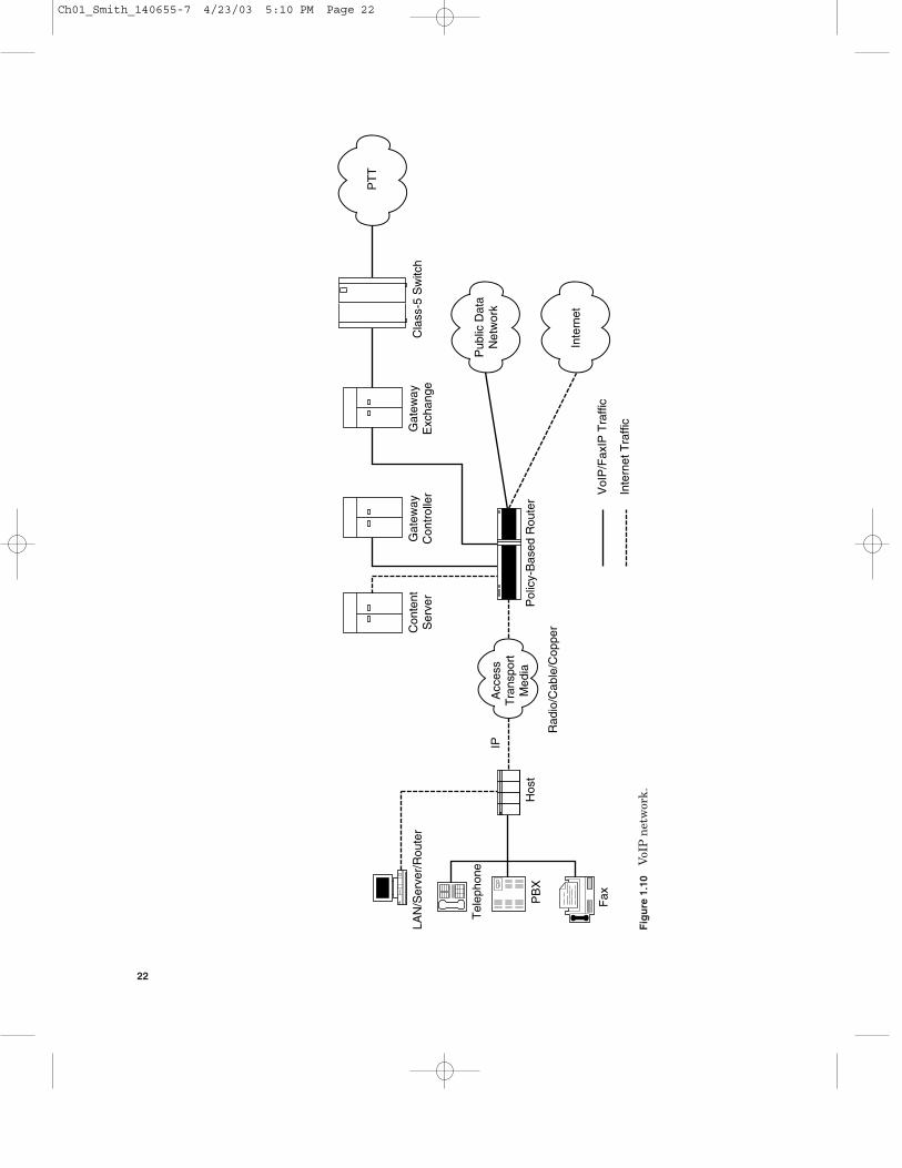
Figure 1.10 depicts the major components involved with providing VoIP,either as a direct service or as an alternative transport medium that the wire-less operator uses to be more cost competitive or better yet to improve the mar-gin. As Fig. 1.10 suggests, VoIP can be delivered either directly to a public datanetwork or via the Internet depending on the service-level agreement (SLA)used. In addition, the diagram depicts the issue of the operator using VoIP asa medium for handling voice traffic into the switching complex where it thenconverts the IP traffic into classical TDM traffic for interfacing to the PTT forcall delivery.
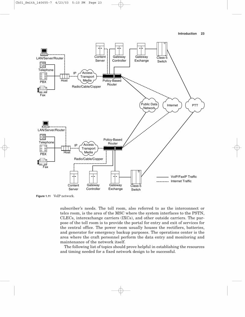
Figure 1.11 depicts the connection between a wireless operator in one mar-ket and its operation in another market. The diagram can, of course, be meantfor an ISP, CLEC, or large corporation.
Voice over IP is the most flexible choice for voice transport since it can runover any layer-one or layer-two infrastructure. This flexibility is particularlyimportant in heterogeneous environments like LMDSs.
1.12 Typical Central Office
Figure 1.12 is a generic mobile telephone center configuration. The mobileswitching center (MSC) is the portion of the network which interfaces theradio world to the public switched telephone network (PSTN). In mature sys-tems there are often multiple MSC locations, and each MSC can have severalcellular switches located within each building.
A mobile telephone switching office (MTSO) is commonly referred to as theMSC and is anything but typical. Although a MSC typically delivers voiceservices, the particular services that can be offered and delivered areextremely varied. For example, in AMPS only voice services could be deliv-ered. GSM system voice along with short messaging service (SMS) serviceswould be provided. However, with the advent of Internet and 2.5/3.0G (pack-et-based mobile) services, many residential MSCs which primarily deliveredvoice services are now transitioning from a circuit-switching to a packet-switching system.
A simplified example of a typical MSC layout is shown in Fig. 1.12.Naturally, when determining the dimensions and specific equipment requiredfor the facility, one will need to factor in the type of services to be provided as well as the time frame the design is to encompass (i.e., the growth poten-tial needed).
Typically a MSC consists of an equipment room, toll room, power room,and operations room. The functions of each room are unique. The equipmentroom has the switching and packet platforms for treating and servicing the
Introduction 21
Ch01_Smith_140655-7 4/23/03 5:10 PM Page 21
Hos
t
LAN
/Ser
ver/
Rou
ter
Tel
epho
ne
PB
XR
adio
/Cab
le/C
oppe
r
IP
Fax
Pol
icy-
Bas
ed R
oute
r
Con
tent
Ser
ver
Gat
eway
Con
trol
ler
Gat
eway
Exc
hang
eC
lass
-5 S
witc
h
Inte
rnet
Tra
ffic
VoI
P/F
axIP
Tra
ffic
Acc
ess
Tra
nspo
rtM
edia
Pub
lic D
ata
Net
wor
k
Inte
rnet
PT
T
Fig
ure
1.1
0V
oIP
net
wor
k.
22
Ch01_Smith_140655-7 4/23/03 5:10 PM Page 22
subscriber’s needs. The toll room, also referred to as the interconnect or telco room, is the area of the MSC where the system interfaces to the PSTN,CLECs, interexchange carriers (IXCs), and other outside carriers. The pur-pose of the toll room is to provide the portal for entry and exit of services forthe central office. The power room usually houses the rectifiers, batteries,and generator for emergency backup purposes. The operations center is thearea where the craft personnel perform the data entry and monitoring andmaintenance of the network itself.
The following list of topics should prove helpful in establishing the resourcesand timing needed for a fixed network design to be successful.
Introduction 23
Host
LAN/Server/Router
Telephone
PBX
Radio/Cable/Copper
IP
Fax
Policy-BasedRouter
ContentServer
GatewayController
GatewayExchange
Class-5Switch
Host
LAN/Server/Router
Telephone
PBX
Radio/Cable/Copper
IP
Fax
ContentServer
GatewayController
GatewayExchange
Class-5Switch
Internet TrafficVoIP/FaxIP Traffic
Policy-BasedRouter
AccessTransport
Media
AccessTransport
Media
InternetPublic DataNetwork
PTT
Figure 1.11 VoIP network.
Ch01_Smith_140655-7 4/23/03 5:10 PM Page 23

Equipment room
� Class 5 switch� ATM switches� Voice mail system� Servers� Billing system
Toll room
� Signaling transfer point (STP)� DXX (cross connect switch) equipment� Routers� Intercept equipment
This list does not address the issue of colocation with other service providersand the need to create a separate area for the operator to maintain andupgrade its equipment.
24 Chapter One
Toll Room
Power RoomNOCOperations
Switching/Packet Room
Class-5 Swtich
Voice Mailand
BillingPlatform
ServersATM/BSC
DDFODF
SONET
DXX
DXX
Routers
Routers
Routers
Intercept
Emergency PowerGenerator
Figure 1.12 Typical CO layout.
Ch01_Smith_140655-7 4/23/03 5:10 PM Page 24