ch2mhill engineeringchangenotice - hanford site · ch2mhill engineeringchangenotice ... persection...
TRANSCRIPT
t:)
CH2M HILL ENGINEERING CHANGE NOTICE1a. ECN 722818 R 0
Page 1 of 9 ® DM q FM q TM 1 b. Proj. ECN N/A - - R
2. Simple Modification 3. Design Inputs - For full ECNs, record information on the ECN-1 Form ( not 4. Date
® Yes q No required for Simple Modifications) 1/19/05
5. Originator's Name, Organization, MSIN, & Phone No. 6. USQ Number 7. Related ECNs
Owen Nelson, 7G330, R3-25, 3-1610 No. - - - R- N/A
® N/A
8. Title 9. Bldg. I Facility No. 10. Equipment I Component ID 11. Approval Designator
Specification for a Primary Exhaust System For 241-C POR-126/127 ESQRWaste Tank Ventilation
12. Engineering Documents/Drawings to be Changed (Incl. Sheet & Rev. Nos.) 13. Safety Designation 14. Expedited/Off-ShiftECN?
RPP-21568 Rev. 0 q SC q SS q GS ® N/A q Yes ® No
15a. Work Package Number 15b. Modification Work Completed 15c. Restored to Original Status (TM) 16. Fabrication SupportECN?
N/A q Yes ® NoN/A N/A
Responsible En ineer/ Date Rosponsible Engineer/ Date
17. Description of the Change (Use ECN Continuation pages as needed)
Details of changes:Section 3.2.9 (Electrical Grounding).
Was: all ducts joints using non-conductive gasket material shall have grounding jumpers provided across the connection.
Is: Verbiage deleted.
Design Change Summary:
This requirement is not necessary since an existing path for conductivity already exists in the design. The bolts are ASTM A193 Gr B8(stainless). Nuts are ASTM A194 Gr 8F (Stainless). The washers are 18-8 stainless. The flanges are ASTM A182 Gr F 304L (stainless).Conductivity continuity will be maintained through joints by like materials.
18. Justification of the Change (Use ECN Continuation pages as needed) 19. ECN Category
The Justification for each change is explained in the specific item Design Change Summary, sheets 3through 9. ® Direct Revision
q SupplementalNote: These documents do not implement any permanent or temporary changes to the facility or
q void/Canceiprocdures. The USQ process, therefore, is not applicable.
ECN Yvoe
q Supercedure
q Revision
20. Distribution Release Stamp
Name MSIN Name MSIN
B. Zuroff 57-67 W. T. Thompson 57-66 MA n
'
05
QO.D. Nelson R3-25 /^ ^ M t=(,^ o
J.G. Propson S7-70DATE:
HANFORD
T.L. Bennington R3-25 STA;^ RELEABE tD:
R. L. Brown S7-75
S.D. Doss 57-03
T.R. Farris S7-24
_i^
A-6003-563.1 (09/04)

1a. ECN 722818 R 0CH2M HILL ENGINEERING CHANGE NOTICE
Page 2 of 9 ® DM q FM q TM 1 b. Proj. ECN N/A - - R
21. Revisions Planned (Include a brief description of the contents of each revision) 22. Design Basis
None Documents
® Yes q NoNote: All revisions shall have the approvals of the affected organizations as identified in block 11 "Approval Designator," on page 1of this ECN.
23. Commercial Grade Item Dedication Numbers (associated with this 24. Engineering Data Transmittal Numbers (associated with this designdesign change) change, e.g., new drawings, new documents)
N/A EDT-820920
25. Other Non En ineerin not in HDCS) documents that need to be modified due to this chan ge
Type of Document Document Number Update Completed On Responsible Engineer (print/sign and date)
Alann Response Procedure N/A N/A N/A
Operations Procedure N/A N/A N/A
Maintenance Procedure N/A N/A N/A
Type of Document Document Number Type of Document Document Number
N/A NiA N/A N/A
N/A N/A N/A N/A
N/A N/A N/A N/A
N/A N/A N/A N/A
N/A N/A N/A N/A
N/A N/A N/A N/A
26. Field Change Notice(s) Used? NOTE: ECNs are required to record and approve all 27. Design Verification Required?
Yes Noq ®
FCNs issued. If the FCNs have not changed theq Yes
®No
original design media then they are just incorporatedIf Yes, Record Infonnation on the ECN-2 Form, into the design media via an ECN. If the FCN did If Yes, as a minimum attach the oneattach form(s), include a description of the interim change the original design media then the ECN will page checklist from TFC-ENG-resolution on ECN Page 1, block 17, and identify include the necessary engineering changes to the DESIGN-P-17.permanent changes. original design media.
28. ApprovalsFacility/Project Signatures
EL.t C.rR6ts
Date A/E Signatures at/^ / c
at
Design Authority ^^ff ^ ^ 4"DS Originator/Design Agent O.D. Nelsop^g/(IlC^ S
Resp. Engineer J.G. Propson t46^,Z j- Professional Engineer N/A
Resp. Manager W. T. Thom on 3 JLIA,$' Project Engineer N/A
QualityAssurance T.L. Bennington
ALZ
3-^s Quality Assurance N/A
IS&H Engineer R.E. Butler '451`1^^^ ,3-yTOS' Safety N/A
NS&L Engineer N/A Designer N/A
Environ. Engineer S.D. Doss '^yOA ^S 3- Y- o C^ Environ. Engineer N/A
Engineering Checker Other N/A
Other System Engineer: T.R. Farris -l",-,L 3 3-(:il - Other N/A
Other Rad Con: R. L. Brown DEPARTMENT OF ENERGY / OFFICE OF RIVER PROTECTION
Other Signature or a Control Number that tracks the Approval Signature
Other N/A
Other ADDITIONAL SIGNATURES
Other N/A
Other N/A
A-6003-563.1 (09/04)
CH2M HILL ENGINEERING CHANGE NOTICE 1a. ECN 722818 R 0
CONTINUATION SHEET
Page 3 of 9 1 b. Proj. ECN N/A - - R
Document/Drawing No. RPP-21568 Sheet N/A Revision 0
17. Description of the Change Cont.
Section 3.3.2.9 ( Isolation Valves).
Was: Stem packing shall be Teflon and the resilient seat shall be Buna-N.
Is: Stem packing shall be Teflon and the resilient seat shall be EPDM.
Design Change Summary:
Per Section 3.2.5.1 of RPP-21568 Rev. 0, the minimum ambient air temperature is -32 degrees F. Per the valve manufactures datasheets, Buna-N gasket is only rated to 0 degrees F. However, EPDM is rated to -40 degrees F. In order to meet this requirement,EPDM is required
Section 3.3.2.9 (Isolation Valves).
Was: Isolation valves shall meet the design requirements of ASME B31.3.
Is: Isolation valves shall meet the design requirements of ASME B31.1.
Design Change Summary:
Per the requirements of RPP-19233 Rev. 0 (General WAC 246-247 Technology Standards Exemptions for Waste Tank VentilationSystems) Section 4.4.3 (Section DA, Dampers and Louvers), the applicable code is ASME B31.1.
Section 3.3.2.13 (Condensate Drain and Seal Pot System) a).
Was: The system shall be designed to drain and capture any condensate located in the heater housing, the filter train assembly, or thefan housing to the buyer's waste tank(s) or collection tank/system (as determined by the buyer) located at the Hanford site. Thecondensate shall be returned to the tank/collection point by use of either a gravity drain or condensate pump. The drain systemwill need to operate effectively at the maximum negative pressure capacity of the fan. Individual lines from each drainage pointin the system shall be sloped a minimum of 1/8" per foot to the seal pot.
Is: The system shall be designed to drain and capture any condensate located in the heater housing, the filter train assembly, or thefan housing to the buyer's waste tank(s) or collection tank/system (as determined by the buyer) located at the Hanford site. Thecondensate shall be retumed to the tank/collection point by use of either a gravity drain or condensate pump. Electrical power forthe condensate pump will be provided by an off skid source. The drain system will need to operate effectively at the maximumnegative pressure capacity of the fan. Individual lines from each drainage point in the system shall be sloped a minimum of 1/8"per foot to the seal pot.
Design Change Summary:
The condensate pump is being powered by an off-skid source through a hardwired relay. This off skid branch circuit is connecteddirectly to the condensate pump. The condensate pump will be controlled by the exhauster PLC. The existing 120VAC power systemdoes not have the capacity to supply power to the condensate pump.The system engineer concurred with this approach.
Note: An AutoCAD page may be used in place of this form (the header section items must be included on the AutoC:AD page).
A-6003-563.1 (09/04)
CH2M HILL ENGINEERING CHANGE NOTICE 1a. ECN 722818 R 0
CONTINUATION SHEET
Page 4 of 9 1 b. Proj. ECN N/A -
Document/Drawing No. RPP-21568 Sheet N/A Revision 0
17- Description of the Change cont.
Section 3.3.2.13 (Condensate Drain and Seal Pot System) e).Was: The seal pot piping materials and construction shall conform to the requirements of ASME B31.3, Chapter 111. The piping shall be ASTM A 312,
Grade TP 304L and fittings shall be ASTM A 403, Class WP 304L. All piping shall be pressure tested in accordance with ASME B31.3 as anassembly with the filter housing.
Is: The seal pot piping materials and construction shall conform to the requirements of ASME B31.3, Chapter III. The piping shall be ASTM A 312,Grade TP 304L and fittings shall be ASTM A 403, Class WP 304L. All piping shall be pressure tested in accordance with methods of ASME B31.3as an assembly with the filter housing at an pneumatic test pressure of 2 psig.
Design Change Summary:
ASME B31.3 requires a test pressure of 15 psig. This is a pressure the condensate drain and seal pot system will never achieve. Maximum pressurethis system could possibly encounter would be the maximum fan static pressure of @ 30" of water. A test pressure of 2 psig was seler.ted as areasonable test pressure per engineering judgment.
Section 3.3.3.1 (Service Power).
Was: Dedicated non-ground fault interrupted (non-GFI) circuits shall be provided for the stack monitoring and sampling and control circuits.
Is: Deleted verbiage
Design Change Summary:
In order to meet the requirements of UL-508 as required in Section 3.3.3.6 (Wiring Practices and Electrical Safety Requirements), "Dedicated non-grounding fault interrupted circuits being deleted" arenot allowed.
Section 3.3.3.1 (Service Power).
Was: Seller shall provide calculations for and appropriately label electrical components (disconnects, etc.) with are flash hazard potentials.
Is: Deleted verbiage
Design Change Summary:
CHG will be providing the calculations and detennining labeling requirements for the flash hazard. CHG had been waiting for the electrical design forthe power system which will provide electricity to the exhausters to be completed. This is required to determine the electrical potential that will beavailable. An A/E is providing the design for the electrical power to the exhausters.
Sectlon 3.3.3.2 ( Mini-Power Zone).
Was: Capacity shall be included in mini-power zone to power additional customer-installed exhauster-to-tank(s) heat trace lines, approximately 300 feetworth ( assume same power rating as other exhauster heat trace).
Is: Deleted verbiage
Design Change Summary:
The existing exhauster 120VAC power system does not have the capacity to supply power to trace extemal to the exhauster. Power to supply the farmtrace heat will be provided by a new farm electrical system, not the exhauster power distribution system.
Note: An AutoCAD page may be used in place of this form (the header section items must be included on the AutoCAD page).

CH2M HILL ENGINEERING CHANGE NOTICE 1a. ECN 722818 R 0
CONTINUATION SHEET
Page 5 of 9 1 b. Proj. ECN N/A
Document/Drawing No. RPP-21568 Sheet N/A Revision 0
17. Description of the Change Cont.
Section 3.3.3.5 ( Cabinet Temperature Control)
Was: Heating and cooling components shall be powered with DC voltage. Thermostats shall be rated for outdoor use and mountedexternally for temperature changes made without opening cabinets. In addition, external cabinet temperatures shall be displayed.
Is: The sample cabinet shall include the following: 1) Cooling fan shall be powered with DC voltage; 2) Thermostats shall be rated foroutdoor use and mounted externally for temperature changes made without opening cabinets; and 3) internal cabinet temperature shallbe displayed on the outside of the cabinet.
Design Change Summary:
Clarification of information
Section 3.3.4.1 ( Pressure Monitorinol
Was: The system shall also have interlocks to shutdown the exhaust fan on certain abnormal tank pressure situations.
Is: Deleted verbiage
Design Change Summary:
This requirement was removed since vacuum relief devices will be installed at each tank. The vacuum relief devices will be the first lineof defense for tank pressure / vacuum abnormalities.
Section 3.3.4.3 (Stack Monitorina)
WAS: The exhaust stack monitoring system in compliance with 40 CFR 61.93 (b)(1 Xi), 40 CFR 61.93 (bx1)(ii), 40 CFR 61, Subpart H,"NationaV Emission Standards for Emissions of Radionuclides Other Than Radon from Department of Energy Facilities" and 40 CFR 52Appendix E, "Protection of Environment".
Is: The exhaust stack monitoring system in compliance with 40 CFR 61.93 (b)(1)(i), 40 CFR 61.93 (b)(1)(ii), 40 CFR 61, Subpart H,"National Emission Standards for Emissions of Radionuclides Other Than Radon from Department of Energy Facilities" and 40 CFR 52Appendix E, "Protection of Environment". Compliance with these requirements may be shown with data from the W-314 exhausters.
Design Change Summary:
Stack sampling system identical to W-314 design. W-314 design was designed and tested to 40 CFR 52 Appendix E. Requalification ofstack is not required.
Note: An AutoCAD page may be used in place of this form ( the header section items must be included on the AutoCAD page).
CH2M HILL ENGINEERING CHANGE NOTICE 1a. ECN 722818 R 0
CONTINUATION SHEET
Page 6 of 9 1 b. Proj. ECN N/A - - R
Document/Drawing No. RPP-21568 Sheet N/A Revision 0
17. Description of the Change Cont.
Section 3.3.4.3 (Stack Monitoring) a) SamDle Collection System
Was: The sample collection system shall be designed to operate in a pH range of 10-14, RH of 85% (or optionally use a sample line air dryer if othersystem components cannot meet humidity requirement), and a temperature range of 27 to 75 °C (80 to 167 °F).
Is: The sample collection system shall be designed to operate in a pH range of 10-14, RH of 85% (or optionally use a sample line air dryer if othersystem components cannot meet humidity requirement), and a temperature range of 27 to 48 °C (80 to 120 °F).
Design Change Summary:
The original design for the 241-C and W-314 exhausters required the use of a new design from Ebedine for a high temperature (167 degrees F). The167 degrees F requirement is only valid in Double shell tanks with multiple mixer pumps running for an extended (months) period of time. CAM detectorhead. Unfortunately, while W-314 was trying to qualify these heads at PNNL, they failed to pass qualification testing. The 241-C exhauster procurementspecification also had CAM temperature requirements for the high temperature CAMs. Since these CAMs are not available, the decision was made touse the standard AMS-4 CAM system for testing and initial operations. These CAMs have a operational upper limit of 122 degrees F.
Section 3.3.4.3 ( Stack Monitoring) fl Data CollectioNStorage Caoabilitv.
Was: The PLC will interface with the LAN system to store the rates and totals for historical reference.
Is: Deleted verbiage
Basis: This design feature is not required by SST engineering.
Section 3.3.4.3 (Stack Monitorina) al Vacuum System
Was: The vacuum pumps and associated equipment shall be mounted in an environmentally controlled cabinet. The cabinet shall be insulated (seeSection 3.3.2.14) and its vents shall be easily closeable (e.g., sliding doors/louvers) in winter months.
Is: Deleted verbiage
Design Change Summary:
This requirement is not required since the vacuum pumps and associated equipment are rated for outdoor use.
Section 3.3.4.4 ( Liquid Monitoring)
Was: The transmitters shall be a discrete signal switch type with 2 adjustable positions for the glycol heater transmitter (high and low level) and 5adjustable positions for the seal pot transmitter (high, high-high, pump control, low, low-low level).
Is: Deleted verbiage
Design Change Summary:
This was a design feature that was desired for the new 241-C exhausters based upon experience with existing portable exhausters. Unfortunately, aninstrument does not exist that will perform these functions in the specified environment.
Note: An AutoCAD page may be used in place of this fonn (the header section items must be included on the AutoCAD page).

CH2M HILL ENGINEERING CHANGE NOTICE 1a. ECN 722818 R 0
CONTINUATION SHEET
Page 7 of 9 1 b. Proj. ECN N/A - - R
Document/Drawing No. RPP-21568 Sheet N/A Revision 0
17. Description of the Change Cont.
Section 3.3.4.5 ( Programmable Loaic Controller).
Was: Separate power supplies shall be provided for the sample system and the loop power required by the pressure transmitters.
Is: Deleted verbiage
Design Change Summary:
Initially, this was a desired design feature imposed upon the new 241-C exhausters. Subsequently, a decision was made not to modify the existingexhauster electrical design. The system engineer concurred with this approach.
Section 3.3.5.41Weldina Procedures and Qualifications)
Was: The seller shall submit copies of all welding procedures, procedure qualification records, and welder qualification records to be employed in theperformance of this purchase order.
Is: The seller shall submit copies of all welding procedures, procedure qualification records required for the performance of this purchase order.
Design Change Summary:
Welding and NDE procedures were submitted and approved by CHG QA and a CHG welding engineer. Premier requested that welder qualificationrecords not be submitted to CHG due to the number of welders that might work on the exhausters. CHG QA concurred, but instituted a QAIP (QualityAssurance Inspect Plan) that had AVS verify welder qualifications at various times during fabrication. Fabrication is complete and all welderqualifications were found acceptable and documented per the CHG QAIP.
Section 4.1.2 (Rotatina Eauioment Balancing and Vibration Criteria).
Was: When vibration readings are taken, the exhauster shall be bolted to a level/flat concrete pad free of major cracks in order to simulate installationconditions at the Hanford site.
Is: When vibration readings are taken, the exhauster shall be placed on a concrete pad free of major cracks.
Design Change Summary:
This will produce the most extreme vibration condition and will bound the vibration testing.
Section 4.1.3 (Filter Housina Testinal e1.
Was: HEPA filter element holding frames at each filter position shall be pressure decay leak tested in accordance with the requirements of ASME AG-1,TabVe SA-B-1310. The leak rate shall not exceed 0.6% (Basis: RPP-16920) of the rated flow adjusted for section area (per ASME AG-1, Table SA-B-1310, Note 1).
Is: e) HEPA filter element holding frames at each filter position shall be pressure decay leak tested. The leak rate shall not exceed 0.1% of the housingvolume per hour at the system leak test pressure as defined in ASME N509, Section 4.6.4.
Design Change Summary:
The leak rate of 0.6% was not correct. This leak rate was calculated per the housing volume as shown in RPP-16920. The housing volume in RPP-16920 is smaller than the 241-C exhausters. Per TFC-ENGSTD-07, REV C, section 3.3.5.4 (Inspection and Testing), "The leak rate shall not exceed0.1% of the housing volume per hour at the system leak test pressure as defined in ASME N509, Section 4.6.4.".
Note: An AutoCAD page may be used in place of this form (the header section items must be included on the AutoCAD page).

CH2M HILL ENGINEERING CHANGE NOTICECONTINUATION SHEET
Page 8 of 9
1a. ECN 722818 R 0
1b. Proj. ECN N/A- - R
Document/Drawing No. RPP-21568
17. Description of the Change Cont.
Section 4.1.3 (Filter Housina Testing) fl.
Sheet N/A Revision 0
Was: The filter train, drain piping, and seal pot shall be pressure decay leak tested before pre-filter and HEPA filters are installed. Test shall beconducted to meet the requirements of ASME AG-1, Table SA-B-1 310. The leak rate shall not exceed 0.6% (Basis: RPP-16920) of the rated flowadjusted for section area (per ASME AG-1, Table SA-B-131 0, Note 1)
Is: The filter train, drain piping, and seal pot shall be pressure decay leak tested before pre-filter and HEPA filters are installed. The leak rate shall notexceed 0.1 % of the housing volume per hour at the system leak test pressure as defined in ASME N509, Section 4.6.4.
Design Change Summary:
The leak rate of 0.6% was not correct. This leak rate was calculated per the housing volume as shown in RPP-1 6920. The housing volume in RPP-16920 is smaller than the 241-C exhausters. Per TFC-ENG-STD-07, REV C, section 3.3.5.4 ( Inspection and Testing), "The leak rate shall not exceed0.1% of the housing volume per hour at the system leak test pressure as defined in ASME N509, Section 4.6.4.".
Table 5-1 Definitive Desian Reoort Documentation. Drawinas.
Was: Requirement for P&ID drawings.
Is: Deleted verbiage
Design Change Summary:
During the early stages of the ventilation design and fabrication effort, two copies of the P&ID were being maintained. A decision was inade to updatethe CH2M Hill P&ID drawing set relinquishing the fabrication vendor from having to supply them. TFC-ENG-STD-10, REV.A-3 " Drawing Standard"addresses uniform drawing symbology. This standard will be in effect for the life cycle of this drawing set.
Section 5.6.6.3 ( Pioina and Instrumentation Diaurams).
Was: All instruments and devices shall be shown symbolically and identified by letters that are found in ISA 5.1, section 3. Show all instrumentation onthe P&ID. The P&ID shall define and show in schematic form the piping, equipment and instrumentation adequately for subsequent engineering designmodifications and operation. The object of the P&ID is to provide sufficient information on all process and service lines, equipment, instruments, andcontrols. P&ID drawings shall be in accordance with buyer-supplied procedures, as well as the following guidelines:
P&ID Drafting Guidelines• Crossing lines must not touch. If possible, break lines in the vertical direction only.• Break instrument lines crossing process and service lines.• Keep parallel lines at least Y. inch apart.• Instrument supply or signal lines entering or leaving the P&ID are noted by hollow arrows.• Draw instrument identification balloons 9/16-inch diameter. For P&ID line type symbols see ISA 5.1.
Is: Deleted verbiage
Design Change Summary:
During the early stages of the ventilation design and fabrication effort, two copies of the P&ID were being maintained. A decision was made to updatethe CH2M Hill P&ID drawing set relinquishing the fabrication vendor from having to supply them. TFC-ENG-STD-10, REV.A-3 " Drawing Standard"addresses uniform drawing symbology. This standard will be in effect for the life cycle of this drawing set.
Note: An AutoCAD page may be used in place of this form (the header section items must be included on the AutoCAD page).
CH2M HILL ENGINEERING CHANGE NOTICE 1a. ECN 722818 R 0
CONTINUATION SHEET
Page 9 of 9 1 b. Proj. ECN N/A - - R
Document/Drawing No. RPP-21568 Sheet N/A Revision 0
17. Description of the Change Cont.
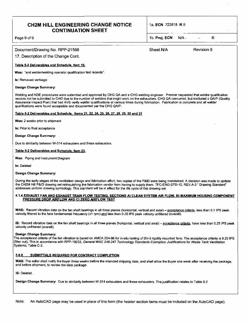
Table 5-2 Deliverables and Schedule , Item 16 .
Was: "and welder/welding operator qualification test records".
Is: Removed verbiage
Design Change Summary:
Welding and NDE procedures were submitted and approved by CHG QA and a CHG welding engineer. Premier requested that welder qualificationrecords not be submitted to CHG due to the number of welders that might work on the exhausters. CHG QA concurred, but instituted a QAIP (QualityAssurance Inspect Plan) that had AVS vedty welder qualifications at various times during fabrication. Fabrication is complete and all welderqualifications were found acceptable and documented per the CHG QAIP.
Table 5-2 Deliverables and Schedule. Items 21. 22. 24. 25. 26. 27. 28. 29. 30 and 31
Was: 2 weeks prior to shipment
Is: Prior to final acceptance
Design Change Summary:
Due to similarity between W-314 exhausters and these exhausters.
Table 5-2 Deliverables and Schedule. Item 23.
Was: Piping and Instrument Diagram
Is: Deleted
Design Change Summary:
During the early stages of the ventilation design and fabrication effort, two copies of the P&ID were being maintained. A decision was made to updatethe CH2M Hill P&ID drawing set relinquishing the fabrication vendor from having to supply them. TFC-ENG-STD-10, REV.A-3 " Drawing Standard"addresses uniform drawing symbology. This standard will be in effect for the life cycle of this drawing set.
4.1.4 EXHAUST FAN AND EXHAUST TRAIN FLOW TESTING. SECTIONS A) CLEAN SYSTEM AIR FLOW. B) MAXIMUM HOUSING COMPONENTPRESSURE DROP AIRFLOW AND CI ZERO AIRFLOW TEST
WAS: Record vibration data on the fan shaft bearings in all three planes (horizontal, vertical and axial) - acceotance criteria , less than 0.1 IPS peakvelocity filtered to the fans fundamental frequency (xl rpm) and less than 0.25 IPS peak velocity unfiltered (overall).
IS: Record vibration data on the fan shaft bearings in all three planes (horizontal, vertical and axial) - acceptance criteria , have less than 0.25 IPS peakvelocity unfiltered (overall).
Design Change Summary:'he acceptance criteria of the fan vibration is based on AMCA 204-96 for in-situ testing of BV-3 rigidity mounted fans. The acceptance criteria is 0.25 IPSfilter out). This in accordance with RPP-19233, General WAC 246-247 Technology Standards Exemption Justifications for Waste Tank Ventilation;vstems. Table C-2.
5.6.6 SUBMITTALS REQUIRED FOR CONTRACT COMPLETION
WAS: The seller shall notify the buyer three weeks before the intended shipping date, and shall allow the buyer one week after receiving the package,and before shipment, to review the data package.
IS: Deleted.
Design Change Summary: Due to similarity between W-314 exhausters and these exhausters. The justification relates to Table 5-2
Note: An AutoCAD page may be used in place of this form (the header section items must be included on the AutoCAD page).
RPP-21568, Re%,, 1
Specification for a Primary Exhaust System forWaste Tank Ventilation
Owen D. Nelson
CH2M Hill
Richland, WA 99352
U.S. Department of Energy Contract DE-AC27-99RL14047
EDT/ECN: ECN 722818 .RO UC:
Cost Center: Charge Code:B&R Code: Total Pages: 10,q
Key Words: Exhauster Procurement Specification
241-C Farm Portable Exhaust Skid Procurement Specification
AbstraCt: Exhaust Skid for C-Farm
Procurment specification for POREX 126 & 127 Exhausters
TRADEMARK DISCLAIMER. Reference herein to any specific commercial product, process, or service by trade name,trademark, manufacturer, or otherwise, does not necessarily constitute or imply its endorsement, recommendation, orfavoring by the United States Govemment or any agency thereof or its contractors or subcontractors.
Printed in the United States of America. To obtain copies of this document, contact: Document Control Services,P.O. Box 950, Mailstop H6-08, Richland WA 99352, Phone (509) 372-2420; Fax (509) 3764989.
Release Approval Date
8005DATE
7
HANFORD
STA ^ ID' QRELEASE
Release Stamp
Approved For Public Release
A-6002-767 (03/01)
Tank Farm Contractor (TFC)RECORD OF REVISION
(^) Documenl Number
RPP-21568Page 1
(2) Title
Specification for a Primary Exhaust System for Waste Tank Ventilation
Change Control Record
3 Authorized for Release
Revision (4) Description of Change - Replace, Add, and Delete Pages(5) Resp. Engr. ( print/sign/date) ( 6) Resp. Mgr. ( print/sign/date)
5.1 Direct Revision Per ECN 722818 Owen D. Nelson War en T. Thompson
A-6003-835 (05/04)

RPP-21568 Rev 1
TABLE OF CONTENTS
1.0 INTRODUCTION..............................................................................................................1
1.1 SCOPE ............................................................................................................................... 11.2 BACKGROUND ............................................................................................................... 1
1.3 SPECIFICATION APPROACH ..................................................................................... 2
2.0 APPLICABLE DOCUMENTS ........................................................................................ 3
2.1 NATIONAL CODES AND STANDARDS ..................................................................... 3
3.0 REQUIREMENTS ............................................................................................................ 6
3.1 ITEM DEFINITION ............. ........................................................................................... 63.1.1 MAJOR SYSTEM COMPONENTS .............................................................................. 63.1.2 INTERFACE DEFINITION ........................................................................................... 6
3.1.2.1 Airstream Design Conditions .......................................................................... 63.1.2.2 Electrical Connection ....................................................................................... 8
3.1.2.3 Seal Pot Condensate Drain .............................................................................. 83.1.2.4 Exhauster Inlet Flange Connection ................................................................ 9
3.1.2.5 Exhaust Skid Structural Installation .............................................................. 9
3.2 CHARACTERISTICS ..................................................................................................... 93.2.1 PERFORMANCE ............................................................................................................. 93.2.2 DESIGN LIFE .................................................................................................................. 93.2.3 SPACE ENVELOPE ........................................................................................................ 93.2.4 MAINTAINABILITY ...................................................................................................... 9
3.2.4.1 Accessibility ...................................................................................................... 93.2.4.2 Decontamination ..... ....................................................................................... 103.2.4.3 Special Tools .................................................................................................... 10
3.2.5 ENVIRONMENTAL REQUIREMENTS ..................................................................... 103.2.5.1 Climate .... ........................................................................................................ 103.2.5.2 Electromagnetic Noise/Radiafion .................................................................. 11
3.2.6 INDUCED LOADS ......................................................................................................... 113.2.6.1 Seismic ............................................................................................................. 113.2.6.2 Wind Loads ..................................................................................................... 123.2.6.3 Snow Loads ..................................................................................................... 133.2.6.4 Ashfall Events ................................................................................................. 133.2.6.5 Dead loads ....................................................................................................... 133.2.6.6 Thermal Forces ............................................................................................... 153.2.6.7 Load Combinations and Allowable Stresses ................................................ 15
3.2.7 STORAGE ..... ................................................................................................................. 163.2.8 TRANSPORTATION ACCELERATIONS ................................................................. 163.2.9 ELECTRICAL GROUNDING . .................................................................................... 163.3 DESIGN AND CONSTRUCTION................................................................................ 173.3.1 MATERIALS, PROCESSES, AND PARTS ................................................................ 17
3.3.1.1 Quality ............................................................................................................. 173.3.1.2 High-strength and Heat Treatments ............................................................. 173.3.1.3 Structural ........................................................................................................ 173.3.1.4 Metallic ............................................................................................................ 173.3.1.5 Deterioration and Protection ..... ................................................................... I83.3.1.6 Fasteners ............ ............................................................................................. 183.3.1.7 Edges ... ............................................................................................................ 1S
3.3.2 EXHAUSTER MECHANICAL COMPONENTS ................................................. ,...... 19
RPP-21568 Rev 1
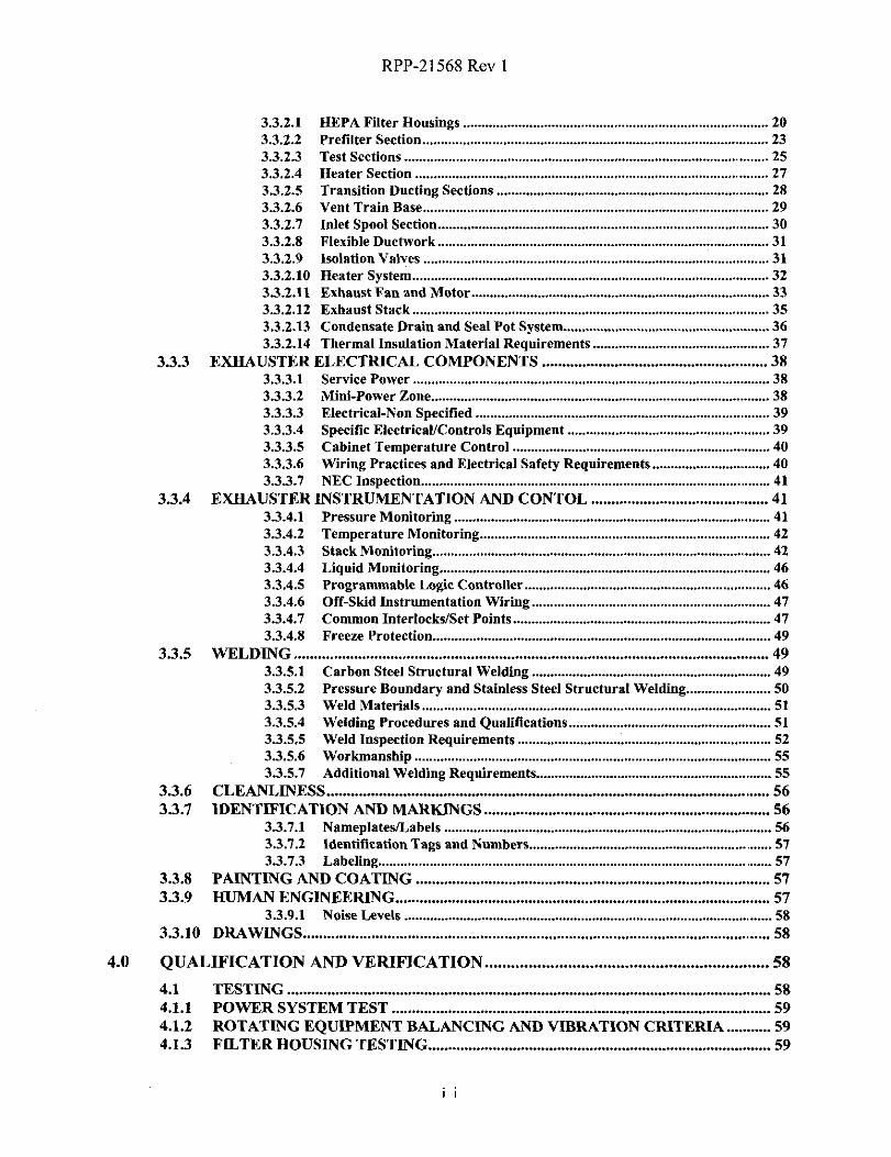
3.3.2.1 HEPA Filter Housings ................................................................................... 20
3.3.2.2 Prefilter Section ....................................................................... ........................ 233.3.2.3 Test Sections ............................................................................ ....................... 253.3.2.4 Heater Section ......................................................................... ....................... 27
3.3.2.5 Transition Ducting Sections .................. ................................. ....................... 28
3.3.2.6 Vent Train Base ....................................................................... ....................... 29
3.3.2.7 Inlet Spool Section ................................................................... ....................... 30
3.3.2.8 Flexible Ductwork ................................................................... ....................... 31
3.3.2.9 Isolation Valves ....................................................................... ....................... 313.3.2.10 Heater System .......................................................................... ....................... 323.3.2.11 Exhaust Fan and Motor .......................................................... ....................... 33
3.3.2.12 Exhaust Stack .......................................................................... ....................... 353.3.2.13 Condensate Drain and Seal Pot System................................. ....................... 363.3.2.14 Thermal Insulation Material Requirements ......................... ....................... 37
3.3.3 EXHAUSTER ELECTRICAL COMPONENTS ................................... ..................... 383.3.3.1 Service Power .......................................................................... ....................... 383.3.3.2 Mini-Power Zone ..................................................................... ....................... 383.3.3.3 Electrical-Non Specified ........................................................ ........................ 393.3.3.4 Specific ElectricaUControls Equipment ............................... ........................ 39
3.3.3.5 Cabinet Temperature Control .............................................. ........................ 40
3.3.3.6 Wiring Practices and Electrical Safety Requirements ........ ........................ 403.3.3.7 NEC Inspection ....................................................................... ........................ 41
3.3.4 EXHAUSTER INSTRUMENTATION AND CONTOL ............................................. 413.3.4.1 Pressure Monitoring ....................................................................................... 413.3.4.2 Temperature Monitoring ............................................................................... 42
3.3.4.3 Stack Monitoring............................................................................................ 42
3.3.4.4 Liquid Monitoring .......................................................................................... 463.3.4.5 Programmable Logic Controller ................................................................... 463.3.4.6 Off-Skid Instrumentation Wiring ................................................................. 47
3.3.4.7 Common Interlocks/Set Points ...................................................................... 47
3.3.4.8 Freeze Protection ............................................................................................ 49
3.3.5 WELDING ...................................................................................................................... 493.3.5.1 Carbon Steel Structural Welding ................................................................. 493.3.5.2 Pressure Boundary and Stainless Steel Structural Welding ....................... 503.3.5.3 Weld Materials ............................................................................................... 513.3.5.4 Welding Procedures and Qualifications ....................................................... 513.3.5.5 Weld Inspection Requirements ..................................................................... 523.3.5.6 Workmanship ................................................................................................. 553.3.5.7 Additional Welding Requirements ................................................................ 55
3.3.6 CLEANLINESS .............................................................................................................. 563.3.7 IDENTIFICATION AND MARKINGS ....................................................................... 56
3.3.7.1 Nameplates/Labels ......................................................................................... 563.3.7.2 Identification Tags and Numbers .................................................................. 573.3.7.3 Labeling ............................................................................................................ 57
3.3.8 PAINTING AND COATING ..................................................................................,...... 573.3.9 HUMAN ENGINEERING ............................................................................................. 57
3.3.9.1 Noise Levels .................................................................................................... 58
3.3.10 DRAWINGS.................................................................................................................... 58
4.0 QUALIFICATION AND VERIFICATION .................................................................. 58
4.1 TESTING . ....................................................................................................................... 584.1.1 POWER SYSTEM TEST .............................................................................................. 594.1.2 ROTATING EQUIPMENT BALANCING AND VIBRATION CRITERIA ........... 594.1.3 FILTER HOUSING TESTING ..................................................................................... 59
RPP-21568 Rev 1
4.1.4 EXHAUST FAN AND EXHAUST TRAIN FLOW TESTING .................................. 604.1.5 HEAT TRACE CHECK ................................................................................................ 634.1.6 INTERLOCK ALARM CHECK .................................................................................. 634.1.7 GLYCOL HEATER CHECK ....................................................................................... 634.1.8 STACK PRESSURE DECAY TEST ............................................................................ 634.1.9 SAMPLING SYSTEM LEAK TEST ............................................................................ 634.2 VERIFICATION METHODS ....................................................................................... 634.2.1 INSPECTION ................................................................................................................. 634.2.2 ANALYSIS ...................................................................................................................... 644.2.3 ENGINEERING EVALUATION ... .............................................................................. 644.2.4 FEATURE TEST ............................................................................................................ 644.2.5 ACCEPTANCE/SYSTEM TEST .................................................................................. 644.3 VERIFICATION MATRIX............................................................................................ 65
5.0 PROJECT MANAGEMENT ......................................................................................... 69
5.1 DESIGN ............................................................................................................................ 695.1.1 CONCEPTUAL DESIGN ............................................................................................... 69
5.1.1.1 Conceptual Design Report .............................................................................. 69
5.1.2 DEFINITIVE DESIGN .................................................................................................. 705.1.2.1 Definitive Design Report (DDR) ................................................................... 70
5.2 WORK PLAN ................................................................................................................. 755.2.1 MONTHLY STATUS REPORTS ................................................................................. 755.2.2 CONTRACT KICKOFF MEETING ........................................................................... 765.2.3 COMMITMENT TRACKING LIST ........................................................................... 765.3 FABRICATION .............................................................................................................. 765.3.1 GENERAL REQUIREMENTS..................................................................................... 765.3.2 SUBCONTRACTOR IDENTIFICATION................................................................... 775.3.3 FABRICATION AND INSPECTION PLAN............................................................... 775.4 TESTING AND EVALUATION ................................................................................... 785.4.1 ACCEPTANCE TEST PLAN ....................................................................................... 785.4.2 ACCEPTANCE TEST PROCEDURE (ATP) ............................................................. 785.4.3 ACCEPTANCE TEST REPORT (ATR)...................................................................... 785.5 OPERATION/MAINTENANCE PROCEDURES ...................................................... 795.5.1 OPERATION PROCEDURE/MANUAL ..................................................................... 795.5.2 MAINTENANCE/STORAGE PROCEDURES ........................................................... 795.6 SUBMITTALS ................................................................................................................ 805.6.1 SUBMITTALS REQUIRED WITH PROPOSAL ........................................................ 80
5.6.1.1 Preliminary List of Drawings and Documentation ....................................... 805.6.1.2 Quality Assurance Program ........................................................................... 805.6.1.3 Identification of Subcontractors ................................................................... 805.6.1.4 Preliminary Welding and NDE Submittals .................................................. 815.6.1.5 Preliminary Schedule ..................................................................................... 81
5.6.2 SUBMITTALS REQUIRED AFTER RECEIPT OF ORDER .. ................................ 815.6.2.1 Work Plan ....................................................................................................... 815.6.2.2 Detailed Schedule ........................................................................................... 815.6.2.3 Written Status Reports .................................................................................. 81
5.6.3 SUBMITTALS REQUIRED PRIOR TO FABRICATION ........................................ 815.6.3.1 Conceptual Design Report ............................................................................. 815.6.3.2 Preliminary Definitive Design Report .......................................................... 815.6.3.3 Fabrication and Inspection Plan ................................................................... 825.6.3.4 Welding and NDE .......................................................................................... 825.6.3.5 Preliminary Operation and Service Procedures/Manuals .......................... 82
RPP-21568 Rev 1
5.6.3.6 Other Information and Design Data to Evaluate Design ............................. 82
5.6.4 AUTHORIZATION TO START FABRICATION ..................................................... 825.6.5 SUBMITTALS REQUIRED TO START TESTING .................................................. 82
5.6.5.1 Acceptance Test Plan ..................................................................................... 82
5.6.5.2 Acceptance Test Procedure (ATP) ................................................................ 82
5.6.6 SUBMITTALS REQUIRED FOR CONTRACT COMPLETION ............................ 835.6.6.1 Final Design Analysis Report ........................................................................ 83
5.6.6.2 As-Built Drawings and Specifications .. ........................................................ 835.6.6.3 Piping and Instrument Diagram ........... ........................................................ 83
5.6.6.4 Final Calculations........................................................................................... 84
5.6.6.5 Inspection & Testing Reports ........................................................................ 845.6.6.6 Certified Test Reports .................................................................................... 845.6.6.7 Operation and Service Procedures/Manuals ............ ................................... 84
5.6.6.8 Calibration Reports ....................................................................................... 845.6.6.9 Packaging And Shipping Plan ....................................................................... 855.6.6.10 Records Maintenance, Control, and Disposition ......................................... 85
5.7 DOCUMENT CONTROL ... .......................................................................................... 855.7.1 CHANGES TO BUYER'S DOCUMENTS .................................................................. 865.7.2 CHANGES TO SELLER'S DOCUMENTS ......... ....................................................... 865.7.3 OWNERSHIP OF DESIGN MEDIA ............................................................................ 865.8 CORRESPONDENCE ................ ................................................................................... 865.9 QUALITY ASSURANCE PROGRAM ........................................................................ 865.10 PRE-AWARD SURVEYS ............................................................................................... 865.11 RIGHT OF ACCESS ...................................................................................................... 875.12 A SUBMITTAL COMPLIANCE REQUIREMENTS ................................................. 875.13 PACKAGING AND SHIPPING PLAN......................................................................... 875.13.1 CLEANING, PACKAGING AND SHIPPING ............................................................. 87
APPENDIX A: SUSPECT/COUNTERFEIT FASTENER HEADMARK LIST .............A-1
STAINLESS STEEL FASTNERE HEADMARK LISTSUSPECT FASTENER HEADMARK LIST..................
.... A-2
.... A-3
APPENDIX B: MECHANICAL COMPONENT DESIGN SKETCHES ......................B-1
EXHSTR-NOTES-1 .......... ............................................................................................B-2EXHSTR-PARTS-1 .......................................................................................................B-3EXHSTR-PARTS-2 .......................................................................................................B-4EXHSTR-PARTS-3 ...... .................................................................................................B-5EXHSTR-MECH1 .........................................................................................................B-6EXHSTR-MECH2 .........................................................................................................B-7EXHSTR-MECH3 .. .......................................................................................................B-8EXHSTR-MECH4 .........................................................................................................B-9EXHSTR-MECHS .......................................................................................................B-10EXHSTR-MECH6 .......................................................................................................B-11EXHSTR-MECH7 .......................................................................................................B-12EXHSTR-MECH8 .......................................................................................................B-13EXHSTR-MECH9 .......................................................................................................B-14EXHSTR-MECH10 .....................................................................................................B-15EXHSTR-MECHI 1 .....................................................................................................B-16EXHSTR-MECH12 .....................................................................................................B-17EXHSTR-MECH13 ......................................................................................................B-18EXHSTR-MECH14 ......................................................................................................B-19
iv

RPP-21568 Rev 1
EXHSTR-MECH15 .....................................................................................................B-20EXHSTR-MECH16 .....................................................................................................B-21EXHSTR-MECH17 .....................................................................................................B-22EXHSTR-MECH18 .....................................................................................................B-23
EXHSTR-MECH19 .....................................................................................................B-24EXHSTR-MECH2O ............................. ........................................................................B-25
EXHSTR-FRM1 ..........................................................................................................B-26EXHSTR-FRM2 ..........................................................................................................B-27EXHSTR-FRM3 .. ........................................................................................................B-28
APPENDIX C: ELECTRICAL AND INSTRUMENTATION DESIGN SKETCHES......C-1
EXHSTR-P&ID-1 .......................................................................................................... C-2EXHSTR-P&ID-2 .......................................................................................................... C-3EXHSTR-P&ID-3 .......................................................................................................... C-4
EXHSTR-P&ID-4 ......................................................................................................... C-5EXHSTR-P&ID-5 ......................................................................................................... C-6EXHSTR-ELECDIAGRAMS-1 .................................................................................. C-7EXHSTR-ELECDIAGRAMS-2 .................................................................................. C-8EXHSTR-ELECHEATRACE-1 .................................................................................. C-9EXHSTR-ENCLOSURE-1 ........................................................................................ C-10EXHSTR-ENCLOSURE-2 ........................................................................................ C-11EXHSTR-ENCLOSURE-3 ............. ........................................................................... C-12EXHSTR-ENCLOSURE-4 ........................................................................................ C-13EXHSTR-LOOPDIAGRAM-1 .................................................................................. C-14EXHSTR-LOOPDIAGRAM-2 .................................................................................. C-15EXHSTR-LOOPDIAGRAM-3 .................................................................................. C-16EXHSTR-LOOPDIAGRAM-4 .................................................................................. C-17EXHSTR-LOOPDIAGRAM-5 .................................................................................. C-1SEXHSTR-LOOPDIAGRAM-6 .................................................................................. C-19EXHSTR-LOOPDIAGRAM-7 .................................................................................. C-20EXHSTR-LOOPDIAGRAM-8 .................................................................................. C-21EXHSTR-LOOPDIAGRAM-9 .................................................................................. C-22EXHSTR-LOOPDIAGRAM-10 ................................................................................. C-23EXHSTR-LOOPDIAGRAM-11 ..............................................................................,,. C-24EXHSTR-LOOPDIAGRAM-12 ..............................................................................,,. C-25EXHSTR-LOOPDIAGRAM-13 ................................................................................. C-26EXHSTR-LOOPDIAGRAM-14 ................................................................................. C-27EXHSTR-LOOPDIAGRAM-15 ................................................................................ C-28EXHSTR-CONNECTION DIAGRAM-1 ................................................................. C-29EXIISTR-CONNECTION DIAGRAM-2 ................................................................. C-30EXHSTR-CONNECTION DIAGRAM-3 ................................................................. C-31EXHSTR-CONNECTION DIAGRAM-4 ................................................................. C-32EXHSTR-COMMDIAGRAM-1 ................................................................................ C-33EXHSTR-COMMDIAGRAM-2 ................................................................................ C-34EXHSTR-COMMDIAGRAM-3 ................................................................................ C-35
APPENDIX D: STACK MONITORING DESIGN SKETCHES ................................D-1
EXHSTR-GEMS-1 ... .................................................................................................... D-2EXIISTR-GEMS-2 ....................................................................................................... D-3EXHSTR-GEMS-3 ....................................................................................................... D-4

RPP-21568 Rev I
APPENDIX E: OFF-SHID INSTRUMENTATION CONNECTION
SKETCHES (REF) ....................................................................E-1EXHHSTR-REF-1 .........................................................................................................E-2EXHHSTR-REF-2 ................................................................................................... ......E-3EXHHSTR-REF-3 ................................................................................................... ......E-4
EXHHSTR-REF-4 ................................................................................................... ......E-5EXIIHSTR-REF-5 ................................................................................................... ......E-6EXHHSTR-REF-6 ................................................................................................... ......E-7EXHHSTR-REF-7 ................................................................................................... ......E-8EXHHSTR-REF-8 ................................................................................................... ......E-9EXHHSTR-REF-9 .................................................................................................... ....E-10EXHHSTR-REF-10 .................................................................................................. ....E-11EXHHSTR-REF-11 ................................................................................................., ....E-12EXHHSTR-REF-12 ................................................................................................. ....E-13EXHHSTR-REF-13 ................................................................................................. ....E-14EXHHSTR-REF-14 ................................................................................................. ....E-15
vi
RPP-21568 Rev I
SPECIFICATION FOR APRIMARY EXHAUSTER SYSTEMFOR WASTE TANK VENTILATION
1.0 INTRODUCTION
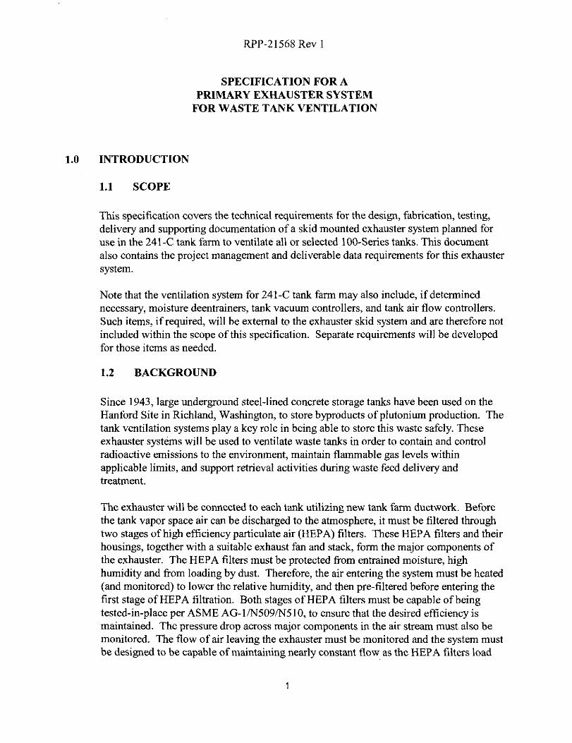
1.1 SCOPE
This specification covers the technical requirements for the design, fabrication, testing,delivery and supporting documentation of a skid mounted exhauster system planned foruse in the 241-C tank farm to ventilate all or selected 100-Series tanks. This documentalso contains the project management and deliverable data requirements for this exhaustersystem.
Note that the ventilation system for 241-C tank farm may also include, if determinednecessary, moisture deentrainers, tank vacuum controllers, and tank air flow controllers.
Such items, if required, will be external to the exhauster skid system and are therefore notincluded within the scope of this specification. Separate requirements will be developedfor those items as needed.
1.2 BACKGROUND
Since 1943, large underground steel-lined concrete storage tanks have been used on theHanford Site in Richland, Washington, to store byproducts of plutonium production. Thetank ventilation systems play a key role in being able to store this waste safely. Theseexhauster systems will be used to ventilate waste tanks in order to contain and controlradioactive emissions to the environment, maintain flammable gas levels withinapplicable limits, and support retrieval activities during waste feed delivery andtreatment.
The exhauster will be connected to each tank utilizing new tank farm ductwork. Beforethe tank vapor space air can be discharged to the atmosphere, it must be filtered throughtwo stages of high efficiency particulate air (HEPA) filters. These HEPA filters and theirhousings, together with a suitable exhaust fan and stack, form the major components ofthe exhauster. The HEPA filters must be protected from entrained moisture, highhumidity and from loading by dust. Therefore, the air entering the system must be heated(and monitored) to lower the relative humidity, and then pre-filtered before entering thefirst stage of HEPA filtration. Both stages of HEPA filters must be capable of beingtested-in-place per ASME AG-1/N509/N510, to ensure that the desired efficiency ismaintained. The pressure drop across major components in the air stream must also bemonitored. The flow of air leaving the exhauster must be monitored and the system mustbe designed to be capable of maintaining nearly constant flow as the HEPA filters load

RPP-21568 Rev 1
with particulate and/or as the pressure in the tank vapor space fluctuates. Instrumentation
will be installed for monitoring and sampling the exhaust gas for radionuclides.
1.3 SPECIFICATION APPROACH
This specification deals with the construction of an exhauster skid system. The buyer hasidentified specific electrical and control interface items to assure commonality in operator
training and maintenance with existing exhausters currently in use at Hanford. The selleris to perform analysis to assure that the components, parts, and assembly requirementsspecified in this specification meet all design and code requirements.
Those pieces of equipment identified by manufacturer, model number, etc., within thespecification shall be furnished as specified, if available. If not available, the buyer shallbe notified and a reasonable substitute will be mutually agreed upon. The seller is free tcselect the component suppliers and specific characteristics of those items not directlyspecified.
The buyer will supply to the seller the computer program used to control the exhauster.Once fabrication is complete, the seller shall perform testing as outlined in thisspecification using the supplied computer program. The buyer or buyer's representativeshall be present to witness the performance of the testing required by this specification.
Drawings provided in the appendices of this specification are intended to providesupplemental direction to assist the seller in understanding the overall scope and designattributes of the equipment assemblies required by this specification. These drawings arenot intended to depict the final configuration. As-built drawings of a previouslyconstructed exhauster system (for Project W-314) nearly identical to the exhauster systemspecified herein, are available upon request and should also be used by the seller to fullyunderstand the scope of the equipment assemblies required by this specification. Itshould be noted that these drawings depict a "dual train" exhauster system consisting oftwo mirror image exhauster units, whereas the system required by this specification is asingle train unit. There are other minor changes to equipment and instrumentation aswell, provided in the text sections of this specification. In any case, the drawingsincluded in the appendices of this specification will NOT be updated during the designand fabrication of the exhauster units built to this specification. Instead, any and allchanges will be formally communicated between the seller and buyer, and the seller willmaintain configuration control of the appropriate drawing sets (i.e., drawings createdfrom the appendices of this specification or from the prior as-built drawings) duringdesign and fabrication as required by Section 5.7. Post-fabrication as-built drawings willbe provided by the seller as required by this specification.

RPP-21568 Rev 1
2.0 APPLICABLE DOCUMENTS
The following codes and standards, including documents referenced therein, form a part of theBasis of Design as specified in the applicable sections of this document. The most currentrevisions shall be used. In the event of conflict between documents referenced herein and therequirements of this specification, the requirements of this specification shall take precedence.Exceptions to any of these codes/standards or any portion(s) thereof shall be allowed only asprovided and approved by the buyer.
2.1 NATIONAL CODES AND STANDARDS
ASCE 7-02 Minimum Design Load for Building and Other Structures
AISC 316/317 Manual of Steel Construction
AISI SG503 Design and Fabrication of Cold-Formed Steel Structures
AMCA 99 Standards Handbook, Publication 99
ANSI BI6.5a-1998 Pipe Flanges and Flanged Fittings
ANSI N13.1-1999 Guide to Sampling Airborne Radioactive Materials in NuclearFacilities
ANSI Y14.1-1995 American National Standard Drawing Sheet Size and Format
ANSI Y14.5M-1994 Dimensioning and Tolerancing
ANST-SNT-TC-I A American Society for Non-Destructive Testing
ASME B31.3-2002
ASME, SEC lI,Part C-2003
ASME, BPVC,SEC IX-2003
ASME N509-2002
Process Piping
Weld Filler Material
Welding and Brazing Qualifications
Nuclear Power Plant Air Cleaning Units and Components
ASME N510-1991 Testing of Nuclear Air Treatment Systems

RPP-21568 Rev I
ASME AG-1-2003 Code on Nuclear Air and Gas Treatment
ASME NQA-1-2000 Quality Assurance Program Requirements for Nuclear Facilities
ASTM A182-2004 Standard Specification for Forged or Rolled Alloy-Steel PipeFlanges, Forged Fittings, and Valves and Parts for High-Temperature Service
ASTM A240-2004 Standard Specification for Heat-Resisting Chromium andChromium-Nickel Stainless Steel Plate, Sheet, and Strip forPressure Vessels
ASTM A312-2004 Standard Specification for Seamless and Welded AusteniticStainless Steel Pipes
ASTM A36-2004 Standard Specification for Carbon Structural Steel
ASTM A403-2004 Standard Specification for Wrought Austenitic Stainless SteelPiping Fittings
ANSUABMA Load Ratings and Fatigue Life for Roller Bearings11-1999
AWS D1.1-2004 Structural Welding Code
AWS D1.2-2003 Structural Welding Code - Aluminum
AWS D1.3-1998 Structural Welding Code - Sheet Steel
AWS D9.1-2000 Specification for the Welding of Sheet metal
AWS QC-1-1996 Standard and Guide for Qualification & Certification of WeldingInspectors
DOE-RL-92-36 Hanford Site Hoisting and Rigging Manual
DOE-STD-1020 Natural Phenomena Hazards Design and Evaluation Criteria forDepartment of Energy Facilities
ERDA 76-21 Nuclear Air Cleaning Handbook
IEEE 112-1996 Test Procedure for Polyphase Induction Motors and Generators
ISA 5.4-1991 Instrument Loop diagrams

RPP-21568 Rev 1
ISA 5.1-1992 Instrumentation Symbols and Identifications
ISO-1940-1-2004 Mechanical Vibration - Balance Quality Requirements of RigidRotors
MICA Midwest Insulation Contractors Association
MIL-STD-889B Dissimilar Metals
MIL-STD-1472F Human Engineering
NCIG-01 Visual Weld Acceptance Criteria for Structural Welding at NuclearPower Plants
NEMA MG-1-2003 Motors and Generators
NFPA 70-2003 National Electrical Code
NFPA 77-2002 Recommended Practice on Static Electricity
NFPA 79-2002 Electrical Standard for Industrial Machinery
NUREG 0700 The Human-System Interface Design Review Guideline
SMACNA HVAC Duct Construction Standards Metal and Flexible1481-1997
SNT-TC-1A-2001 ASNT's Guideline to Personnel Qualification and Certification inNDT
SSPC SP 3-2000 Power Tool Cleaning
UL 508-2003 UL Standard for Safety Industrial Control Equipment SeventeenthEdition
40CFR52 Protection of Environment
40CFR60Method 1, lA, 2, 2C Sampler Location and Placement Design Criteria
40CFR61 National Emission Standards for Hazardous Air Pollutants
5

RPP-21568 Rev I
3.0 REQUIREMENTS
3.1 ITEM DEFINITION
3.1.1 MAJOR SYSTEM COMPONENTS
The major components of the exhauster are:
• Support Skid
• Ductwork
• Isolation Valves
• Heater System
• Filter Train Assembly
• Exhaust Fan and Motor
• Stack
• Condensate Drain and Sea] Pot System
• Power Distribution System
• Instrumentation and Controls
3.1.2 INTERFACE DEFINITION
The seller's design shall incorporate the capabilities to accommodate all interfacerequirements as defined below:
3.1.2.1 Airstream Design Conditions
The design conditions of the airstream entering the exhauster will be from20°F to 150°F at 100% relative humidity with no entrained moisture. Therelative humidity of the air entering the HEPA filter assembly shall notexceed 70% and the relative humidity of the air leaving the exhaust stackshall not exceed 85%. The airstream may contain varying amounts ofhydrogen, nitrous oxide, methane, and ammonia vapors. The airstreamentering the exhauster is drawn from tanks containing a high pH (10-14nominal) waste.
Vapor compounds of the chemical waste concentrations listed in Table 3-1
may be present in the airstream. Minimum and maximum concentrations
for wastes in single-shell tanks (SSTs) and double-shell tanks (DSTs) are

RPP-21568 Rev 1
presented. These concentrations are from the Best-Basis InventoryCalculation Detail Report and Calculation Detail Report - SupplementalAnalytes, queried on June 20, 2004. The Calculation Detail Report listsadjusted concentrations for each waste phase and waste type in the 149SSTs and 28 DSTs. The highest and lowest reported adjustedconcentrations are listed in the table below. Because a tank usuallycontains more than one waste phase and waste type, the actual range: ofaverage tank concentrations would be expected to be smaller than the
range of concentrations listed. For the purposes of this specification,however, the worst case data from either the single shell tank or double
shell tank list shall be considered (since it is possible that the exhaustercould be used to ventilate either type of tank in the future).
Table 3-1 Chemical Composition Range
Double-Shell TankChemical Composition Range
Single-Shell TankChemical Composition Range
Analyte
MinimumConcentration
I
MaximumConcentration
(pg/9) , Analyte
MinimumConcentration
,
MaximumConcentration
(ILg/g)I
Al 1.29E+02 1.40E+05 1 0E+00 2.87E+05
Bi 0.00E+00 8.91E+03 i OE+00 9.28E+04
Ca <1.55E+00 1.07E+05 Ca 0E+00 4.60E+05
C1 5.75E+01 8.07E+03 1 OE+00 1.05E+04
Cr 6.43E+01 2.96E+04 Cr OE+00 2.45E+04
F <2.37E+01 7.43E+04 OE+00 4.52E+04
Fe <2.70E-01 1.04E+05 e OE+00 2.71 E+05
H 0.00E+00 1.96E+02 OE+00 1.49E+03
K 2.76E+02 3.12E+04 0E+00 7.49E+03
La 0.00E+00 1.90E+03 La 0E+00 1.81 E+04
Mn O.OOE+00 3.48E+04 Mn OE+00 6.54E+04
Na 2.08E+04 2.25E+05 Na 0E+00 3.26E+05
Ni 0.00E+00 3.08E+03 Ni 0E+00 5.09E+04
NO2O 4.94E+02 1.04E+05 N02 OE+00 1.15E+05
03 6.95E+01 2.22E+05 N03 0E+00 6.00E+05
OH 7.84E-01 6.77E+04 OH 0E+00 2.46E+04
Pb O.00E+00 4.92E+03 Pb 0E+00 1.89E+04
P04 2.99E+02 1 .72E+05 04 0E+00 2.50E-05

RPP-21568 Rev I
Double-Shell TankChemical Composition Range
Single-Shell TankChemical Composition Range
Analyte
MinimumConcentration
t
MaximumConcentration
t Analyte
MinimumConcentration
,
MaximumConcentration
t
Si 6.99E+00 1.73E+04 Si 0E+00 6.52E+05
SO4 1.57E+02 2.47E+04 SO4 0E+00 1.62E+05
Sr O.00E+00 3.56E+02 Sr 0E+00 1.89E+04
TIC as CO3 3.30E+03 1.89E+05 IC as CO3 0E+00 1.81 E+05
TOC O.00E+00 5.06E+04 OC 0E+00 4.25E+04
UTOTAL
Zr
1.01E+00
O.00E+00
3.50E+04
1.14E+05ToTALr
0E+00
0E+00
1.61E+05
3.92E+04
Radionuclides 4.90E-01 4.36E+04 adionuclides 0E+00 9.05E+04
'Radionuclide concentration in µCi/g.
3.1.2.2 Electrical Connection
The exhauster power connection design shall be capable of operating theexhauster from either a 480V, AC terminal buss connection (3-phase, 4-wire) or a standard weld receptacle (480V, 3-phase, 4-wire). A groundinglug shall be incorporated onto the skid (for equipment ground - not thepower system ground). The buyer shall provide location of this lug on theskid. A 2" power conduit routed from the transfer switch enclosure to theduct inlet end of exhaust skid shall be included. This conduit will be usedby the buyer to install power at the Hanford site.
3.1.2.3 Seal Pot Condensate Drain
The condensate shall be returned to the buyer's designated waste tank(s) orcollection tank/system (drain point determined and piping supplied by thebuyer) by use of the exhauster's gravity drain or condensate pumpconnection. A 1" flanged connection shall be provided on the gravitydrain line (used for normal seal pot overflow) and condensate pump line.A 1/2" flanged connection shall also be provided on the seal pot drain line(used for complete draining of the seal pot).
RPP-21568 Rev 1
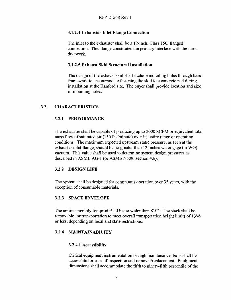
3.1.2.4 Exhauster Inlet Flange Connection
The inlet to the exhauster shall be a 12-inch, Class 150, flangedconnection. This flange constitutes the primary interface with the farmductwork.
3.1.2.5 Exhaust Skid Structural Installation
The design of the exhaust skid shall include mounting holes through baseframework to accommodate fastening the skid to a concrete pad duringinstallation at the Hanford site. The buyer shall provide location and sizeof mounting holes.
3.2 CHARACTERISTICS
3.2.1 PERFORMANCE
The exhauster shall be capable of producing up to 2000 SCFM or equivalent totalmass flow of saturated air (1501bslminute) over its entire range of operatingconditions. The maximum expected upstream static pressure, as seen at theexhauster inlet flange, should be no greater than 12 inches water gage (in WG)vacuum. This value shall be used to determine system design pressures asdescribed in ASME AG-1 (or ASME N509, section 4.6).
3.2.2 DESIGN LIFE
The system shall be designed for continuous operation over 35 years, with theexception of consumable materials.
3.2.3 SPACE ENVELOPE
The entire assembly footprint shall be no wider than 8'-0". The stack shall beremovable for transportation to meet overall transportation height limits of 13'-6"or less, depending on local and state restrictions.
3.2.4 MAINTAINABILITY
3.2.4.1 Accessibility
Critical equipment instrumentation or high maintenance items shall beaccessible for ease of inspection and removallreplacement. Equipmentdimensions shall accommodate the fifth to ninety-fifth percentile of the

RPP-21568 Rev 1
user population when possible (per NUREG 0700, section 6.1 and MIL-STD-1472F, section 5.6). Adequate space and accessibility shall beprovided for removal and replacement of individual instruments orequipment without removal of adjacent equipment. Valves, testpoints/ports, and calibration adjustments shall be accessible. Largeequipment items shall have integral lifting attachments as practical. Thestructural skid frame shall allow convenient access to the filter traincomponents for maintenance and operations.
3.2.4.2 Decontamination
The design shall take into consideration that all components must becapable of being decontaminated and ultimately decommissioned,dismantled, and disposed of as radioactive waste. All material andequipment shall be fabricated and installed to facilitate routine removal,cleaning or decontamination. Attention shall be paid to eliminatingcrevices and obtaining smooth weldments through the entire exhausterflow stream. Longitudinal seams shall be placed in the top quadrant ofductwork.
3.2.4.3 Special Tools
The exhauster system shall be designed to facilitate maintenance withcommercially available tools wherever possible. The seller shall furnishall special tools unique to the seller's equipment that are necessary forinstallation, start-up, operation, maintenance, and adjustment of theequipment and accessories furnished by the seller. The special toolsbecome the property of the buyer. If supplied, the seller shall also providea list of all special tools furnished, identifying the function of each tooland the specific item(s) for which it is used. Seller shall also indicatewhether the tool is required for assembly, disassembly, installation, start-up, operation, maintenance, or adjustment. The seller shall providedetailed drawings or procurement information for the special tools.
3.2.5 ENVIRONMENTAL REQUIREMENTS
3.2.5.1 Climate
This section defines the natural conditions (e.g., weather) in which theexhauster will be subjected to. Equipment shall be designed to operate inthe environmental conditions listed in this section.
• Ambient Air Temperature
10
RPP-21568 Rev 1
The ambient air temperature range is 120°F to -32°F, and with amaximum 24-hour differential of 52°F.
• Relative Humidity
The relative humidity range is 0 to 100% (Rate of change is negligible)
• Surface Precipitation
The surface precipitation is 1.56 inches in a 24-hour period.
• Hail Events
The hail diameter is less than or equal to 0.75 in.
• Sand and Dust
The sand/dust concentration is 1.10x10"51bm/ft2 with a typical size of350 µm.
• Solar Radiation
The maximum expected solar radiation is 900 Langleys per day.
• Glaze
The maximum expected glaze is 1 in.
3.2.5.2 Electromagnetic Noise/Radiation
The control systems shall be designed and constructed such that strayelectromagnetic radiation/noise (i.e. RF, cellular phones, power) does notinterfere with the control circuit function.
3.2.6 INDUCED LOADS
This section defines the induced loads in which the Exhauster will be subjected to.
3.2.6.1 Seismic
a) The exhaust train assembly consisting of components defined inSection 3.1.1 shall be designed to retain structural integrity during andafter a design basis earthquake (DBE). A mathematic analysis forDBE shall be performed unless the manufacturer provides justification
11
RPP-21568 Rev 1
for the conservatism of an alternate method.
b) Seismic qualification of the filter housings as a separate component,shall be based on a seismic shake table test of the housing with HEPAfilter elements installed in accordance with the requirements of ASMEAG-1, Article AA-4350.
c) Table 3-2 shows the response spectra for design motion for theequipment. These design spectra are applied for two horizontal andone vertical direction in a free field. The critical damping used for thedesign and analysis shall be 5 percent.
d) If similar equipment has previously been qualified by means of testingand/or analysis equivalent to those described above, the results of thesetest/analysis may be used to demonstrate seismic qualification if it canbe shown that previous seismic inputs can envelope the responsespectra corresponding to the unit components.
3.2.6.2 Wind Loads
a) The exhaust train assembly consisting of components defined inSection 3.1.1 shall be designed to retain structural and operationalintegrity during and after an extreme wind condition. A mathematicanalysis for this condition shall be performed unless the manufacturerprovides justification for the conservatism of an alternate method.
b) Wind loading design shall be in accordance with the definitions andrequirement of ASCE 7-02 utilizing the following criteria:
1) Wind speed - 80 mph
2) 3 second wind gust - 100 mph
3) Importance factor - 1.0
4) Exposure category - C
5) Horizontal wind missile - yes, 2 x 4 timber plank, 15 Ibs,traveling at 50 mph (73.5 ft/s), maximum trajectory height=30ft.
c) If similar equipment has previously been qualified by means of testingand/or analysis equivalent to those described above, the results of thesetest/analysis may be used to demonstrate wind-loading qualification.
12
RPP-21568 Rev 1
3.2.6.3 Snow Loads
a) The exhaust train assembly consisting of components defined inSection 3.1.1 shall be designed to retain structural and operationalintegrity during and after a snow load condition. A mathematicanalysis for this condition shall be performed unless the manufacturerprovides justification for the conservatism of an alternate method.
b) The ground snow loads are: 15 lb/ft2
3.2.6.4 Ashfall Events
a) The exhaust train assembly consisting of components defined inSection 3.1.1 shall be designed to retain structural and operationalintegrity during and after an ashfall load condition. A mathematicanalysis for this condition shall be performed unless the manufacturerprovides justification for the conservatism of an alternate method.
b) A combination snowfall and ash fall LOAD of 201b/ft2 shall be used.
3.2.6.5 Dead loads
a) The exhaust train assembly consisting of components defined inSection 3.1.1 shall be designed to retain structural and operationalintegrity with dead loads applied. A mathematic analysis for thiscondition shall be performed unless the manufacturer providesjustification for the conservatism of an alternate method.
b) Dead loads include the weights of all permanent materials andequipment, including the structure's own weight. Design dead loadsshall include the weight of all permanent service equipment. Loadcalculations shall include an allowance for any loading anticipated tobe added at a later date. Initially assumed loads shall be revised so thatthe final design reflects the configuration shown on the drawings.
c) The unit weights of materials and construction assemblies forbuildings and other structures shall be those given in ASCE 7-02.Where unit weights are neither established in that standard nordetermined by test or analysis, the weights shall be determined fromdata in manufacturer drawings or catalogs.
13
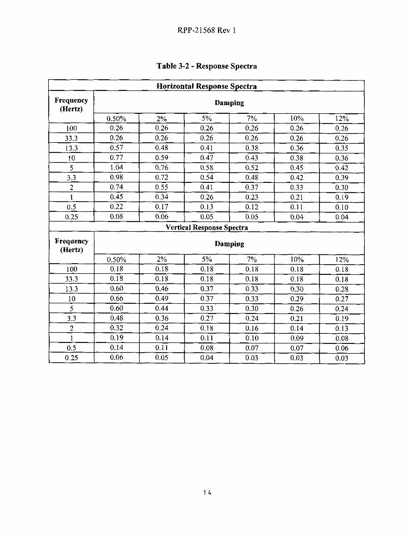
RPP-21568 Rev I
Table 3-2 - Response Spectra
Horizontal Response Spectra
Frequency(Hertz)
Damping
0.50% 2% 5% 7% 10% 12%
100 0.26 0.26 0.26 0.26 0.26 0.26
33.3 0.26 0.26 0.26 0.26 0.26 0.26
13.3 0.57 0.48 0.41 0.38 0.36 0.35
10 0.77 0.59 0.47 0.43 0.38 0.36
5 1.04 0.76 0.58 0.52 0.45 0.42
3.3 0.98 0.72 0.54 0.48 0.42 0.39
2 0.74 0.55 0.41 0.37 0.33 0.30
1 0.45 0.34 0.26 0.23 0.21 0.19
0.5 0.22 0.17 0.13 0.12 0.11 0.10
0.25 0.08 0.06 0.05 0.05 0.04 0.04
Vertical Response Spectra
Frequency(Hertz)
Damping
0.50% 2% 5% 7% 10% 12%
100 0.18 0.18 0.18 0.18 0.18 0.18
33.3 0.18 0.18 0.18 0.18 0.18 0.18
13.3 0.60 0.46 0.37 0.33 0.30 0.28
10 0.66 0.49 0.37 0.33 0.29 0.27
5 0.60 0.44 0.33 0.30 0.26 0.24
3.3 0.48 0.36 0.27 0.24 0.21 0.19
2 0.32 0.24 0.18 0.16 0.14 0.13
1 0.19 0.14 0.11 0.10 0.09 0.08
0.5 0.14 0.11 0.08 0.07 0.07 0.06
0.25 0.06 0.05 0.04 0.03 0.03 0.03
14

RPP-21568 Rev 1
3.2.6.6 Thermal Forces
a) The exhaust train assembly consisting of components defined inSection 3.1.1 shall be designed to retain structural and operationalintegrity caused by Thermal forces. A mathematic analysis for thiscondition shall be performed unless the manufacturer providesjustification for the conservatism of an alternate method.
b) The design of structures shall include the effects of stresses andmovements resulting from variations in temperature. Structures shallbe designed for movements resulting from the maximum seasonaltemperature change. The design shall provide for the lags between airtemperatures and the interior temperatures of massive concretemembers or structures. Consideration shall be given to passive soilloading resulting from thermal growth of subgrade structures.
3.2.6.7 Load Combinations and Allowable Stresses
Load combinations, allowable stresses, and strength requirements for loadconditions that include live load; dead load; snow load; normal operatingloads; and NPH loads of extreme wind, earthquake, flood, and ashfall forall structures, systems, and components shall comply withDOE-STD-1020.
Load factors and load combination for structures, systems, andcomponents
Combine response from various loading to determine structuraldemand as follows.
Where:
DL = DEAD LOAD
LL = LIVE LOAD
RL = ROOF LIVE LOAD
S = SNOW LOAD
W = WIND LOAD
E = EARTHQUAKE
A = ASHFALL
T = THERMAL
C = CREEP/SHRINKAGE
15

RPP-21568 Rev 1
Allowable Stress (AS) Design:
AS = DL + LL + RL(or S)
AS = 0.62 [ DL + LL + RL(or S) + W+ T(or C)]
For shear stress
AS = 0.71 [ DL + LL + RL(or S) + E(or A) + T(or C)]
For all stress other than shear stress
AS = 0.59 [ DL + LL + RL(or S) + or A) + T(or C)]
Ultimate Strength (U) Design:
U = 1.4DL + 1.7LL + 1.7RL(or 1.7S)
U = 1.4 [ DL + T(or C) ]
U = DL + LL + RL(or S) + W(or E or A) + T(or C)
Strength (S) Design: Steel (Load & Resistance Factor Design)
S = 1.4DL
S = 1.2DL + 1.6LL + 0.5(RL or S)
S = 1.2DL + 0.5LL + 1.6(RL or S)
S = DL + LL + RL(or S) + W(or E or A)
3.2.7 STORAGE
The exhauster shall be capable of being stored outside for up to 1 year withoutpermanent damage that would impair the exhauster system from operation. Sheetmetal isolation covers shall be provided on the inlet and exit of the filter train andstack during transport and storage. The seller shall identify any special storagerequirements deemed necessary to protect the mechanical or electronic equipmentfrom this storage requirement.
3.2.8 TRANSPORTATION ACCELERATIONS
The packaged exhauster shall be contained within a shipping container or suitableprotective device. The exhauster shipping container, or protective device, shall bedesigned to support the exhauster so it can withstand a .75g (forward) hardbraking stop and a rearward acceleration of .25g's, as well as shock and vibrationloads associated with transportation.
3.2.9 ELECTRICAL GROUNDING
The exhauster will be properly grounded when installed and connected to a tank.All non-energized metallic objects shall be grounded and bonded per NFPA 70(article 250) to assure grounding of the entire system during any lightning activity.
16
RPP-21568 Rev 1
The exhauster shall also be designed to ensure that the requirements of NFPA 77are met to prevent the build-up of static electricity.
3.3 DESIGN AND CONSTRUCTION
3.3.1 MATERIALS, PROCESSES, AND PARTS
3.3.1.1 Quality
Materials shall be free from any defects or imperfections that may affectperformance. The seller shall not incorporate any rebuilt or refurbishedcomponents into this assembly.
When requested by the buyer, the Supplier shall provide a Certificate ofCompliance that must certify conformance and traceability of suppliedmaterials to the subject Purchase Order/Contract Order. The documentmust be legible and reproducible.
The Supplier shall warrant that "all items furnished under this PurchaseOrder/Contract Order are genuine (i.e., not counterfeit) and match thequality, test reports, markings and/or fitness for use required by thePurchase Order/Contract Order". The statement shall be on supplierletterhead and signed by an authorized agent of the supplier. Anymaterials furnished as part of this Purchase Order/Contract Order, whichhave been previously found to be suspect/counterfeit by the Department ofEnergy, shall not be accepted.
3.3.1.2 High-strength and Heat Treatments
The seller shall identify to the buyer for review of all high-strengthmaterials to be incorporated and applicable post-weld heat treatments.
3.3.1.3 Structural
Materials for all structural members shall be selected in accordance withindustry-accepted procedures.
3.3.1.4 Metallic
Metallic parts shall be of corrosion-resistant metal, or shall be suitablyfinished to resist corrosion. Dissimilar metals, such as those defined byMIL-STD-889, that have active electrolytic corrosion properties shall notbe used in direct contact.
17

RPP-21568 Rev 1
3.3.1.5 Deterioration and Protection
Material subject to deterioration when exposed to climatic and otherenvironmental conditions specified herein shall be protected against suchdeterioration. The use of any protective coating that will crack, scale, orerode due to extremes of climatic or other environmental conditionsduring the required exhauster life shall not be used. All protectivecoatings shall require the concurrence of the buyer.
3.3.1.6 Fasteners
All fasteners provided must meet the following requirements:
Fasteners shall exhibit grade marks and manufacturer's identificationsymbols (head marks) as required in the specifications referenced in thePurchase Order/Contract Order.
Any fasteners supplied with head marks matching those displayed inAppendix A, Suspect/Counterfeit Fastener Head mark list, or facsimilesthereof, shall be deemed to be unacceptable under the terms of thisPurchase Order/Contract Order.
When requested by the buyer, the supplier shall provide a legible andreproducible copy of the manufacturer's Certified Material Test Reports(CMTR). These CMTRs shall report the values of the actual chemical andphysical tests performed on the represented fastener lot/material heat.Fastener packaging/labeling shall be traceable by lot number or otherpositive means to the CMTRs.
Fasteners shall be inspected to verify compliance with the PurchaseOrder/Contract Order requirements. Additionally, fasteners may also besubjected to destructive testing.
3.3.1.7 Edges
All sharp and flame-cut edges shall be deburred.
18
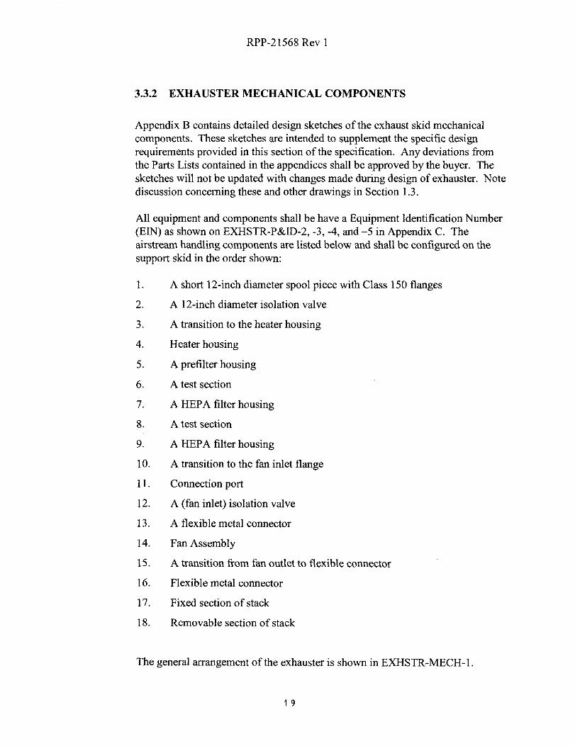
RPP-21568 Rev 1
3.3.2 EXHAUSTER MECHANICAL COMPONENTS
Appendix B contains detailed design sketches of the exhaust skid mechanicalcomponents. These sketches are intended to supplement the specific designrequirements provided in this section of the specification. Any deviations fromthe Parts Lists contained in the appendices shall be approved by the buyer. Thesketches will not be updated with changes made during design of exhauster. Notediscussion concerning these and other drawings in Section 1.3.
All equipment and components shall be have a Equipment Identification Number(EIN) as shown on EXHSTR-P&ID-2, -3, -4, and -5 in Appendix C. Theairstream handling components are listed below and shall be configured on thesupport skid in the order shown:
A short 12-inch diameter spool piece with Class 150 flanges
2. A 12-inch diameter isolation valve
3. A transition to the heater housing
4. Heater housing
5. A prefilter housing
6. A test section
7. A HEPA filter housing
8. A test section
9. A HEPA filter housing
10. A transition to the fan inlet flange
11. Connection port
12. A (fan inlet) isolation valve
13. A flexible metal connector
14. Fan Assembly
15. A transition from fan outlet to flexible connector
16. Flexible metal connector
17. Fixed section of stack
18. Removable section of stack
The general arrangement of the exhauster is shown in EXHSTR-MECH-1
19

RPP-21568 Rev 1
Ventilation system components shall be fabricated, assembled, and tested to meetthe latest requirements of ASME AG-1 and ASME N509/ASME N510. Whereconflicts occur or if one requirement is less stringent, ASME AG-1 takesprecedence.
Items 5 through 9 shall be considered a combined assembly and the product of asingle manufacturer.
3.3.2.1 HEPA Filter Housings
a) The exhaust train assembly will require two (2) HEPA filter housings.These filter housings shall be a Flanders BF Series, I x 2, type 1, righthand access (when facing direction of air flow) and shall be fabricatedfrom 11 and 14 gage, ASTM A240, Type 300 series stainless steelwith a 2-B mill finish. All welded components shall be fabricatedfrom Type 300 series stainless steel, Grade L.
b) Housing hardware material shall meet the requirements for Type 300series stainless steel, excluding the access door knobs which shall becast aluminum.
c) The filter housings shall not exceed a nominal depth of 25" in thedirection of airflow.
d) The filter housings shall be adequately reinforced to withstand thesystem structural capability pressure as defined in ASME AG-1 (orASME N509, section 4.6.6.1).
e) All "pressure retaining" weld joints and seams shall be 100%continuously welded. Weld joints and seams shall be wire brushed orbuffed after final NDE/inspection as required to remove heatdiscoloration, oxidation, all burrs and sharp edges.
f) The housings shall be insulated to a nominal thickness of 2" using 8-lb/cubic foot mineral wool insulation. The insulation shall cover thesides, top, bottom and access doors for the housings and shall fill, tothe maximum extent practical, the external housing voids. Theinsulation shall be permanently sealed into the housing by the weldedinstallation of 11 or 12 gage ASTM A240, Type 300 series stainlesssteel false panels. All welded components shall be fabricated fromType 300 series stainless steel, Grade L.
g) The housings shall accommodate two (2) Flanders GG-F (24" x 24" x
20

RPP-21568 Rev 1
11 1/2") Fluid Seal, Type B (Nuclear Grade) HEPA elements. Filter-
to-housing seal shall be effected by means of a "knife-edge" frame inthe housing that engages with a continuous perimeter channel on theface of a filter element that has been filled with a viscous, non-dryingfluid. The filter elements shall not require any special attachments ordevices to function correctly within the housings.
h) The housings shall be equipped with two (2) static pressure ports. Theports shall be located upstream and downstream of the filter elementson the top of the housing. The port fittings shall be 1/4", Schedule 40,seamless, stainless steel pipe meeting the requirements of ASTMA312, Type 300 series stainless steel. All welded components shall befabricated from Type 300 series stainless steel Grade L. The portsshall extend a minimum of 1" above the insulation false panel andthreaded to accept a 1/4" FNPT fitting.
i) The first filter housing shall be equipped with one (1) temperature port.The port will be located on the top of the housing directly in front ofthe HEPA filter. The port fitting shall be I", Schedule 40, seamless,stainless steel pipe meeting the requirements of ASTM A312, Type300 series stainless steel. All welded components shall be fabricatedfrom Type 300 stainless steel Grade L. The port shall extend aminimum of 1" above the insulation false panel and threaded to accepta 1" FNPT fitting.
j) The housings shall be equipped with a floor drain centered at thebottom of the housing. The drain shall be 1" Schedule 40, seamless,pipe meeting the requirements of ASTM A312, Type 300 seriesstainless steel. All welded components shall be fabricated from'type300 series stainless steel Grade L.
k) A toggle or over-center ("Davis-Lok") type filter element clampingassembly or locking tray shall be used to secure the filter elements inthe housing. The clamping assembly shall apply a sealing force that iseven and uniform across the top and bottom of the filter element. Theclamping assembly or locking tray shall be replaceable.
1) The housings shall be equipped with an access port for the filterelement.
m) The filter element clamping assembly or locking tray shall beaccessible from the access port and shall be operable through anycontainment change-out bags.
21

RPP-21568 Rev 1
n) The housings shall be equipped with filter removal rods to draw thefilters to the change-out position. The removal rods shall be operatedfrom inside the change-out bag, and the filters shall be removed bypulling against the bottom of the filter frame. There shall be nopenetration through the housing for operation of the removal rod. Allchange out operations shall be within the bag so there is a barrierbetween the worker and the filter at all times.
o) The access port shall be equipped with a containment change-out bagadapter. The adapter shall be welded to the housing. The weldedjoints/seams used to fabricate and secure the change-out adapter to thehousing shall be considered "pressure retaining" joints and meet therequirements of 3.3.2.1.e. The adapter shall be hemmed or rolled onits outer edge and include two (2) continuous ribs. The ribs arerequired to hold the containment bag elastic cord and/or safety strapduring filter element bag in/bag out procedures.
p) A containment change-out bag shall be provided for each access portthat meets the airstream design conditions of Section 3.1.2.1. The bagsshall be nominal 5 mils thick, translucent and have elastic O-ring(compatible with the maximum bag temperature) hemmed into theopen end of the bag.
q) A nylon safety strap shall be provided with the bag to prevent the bagfrom slipping off of the access port bag adapter during filter elementbag in/bag out procedures.
r) A nylon-cinching strap shall also be provided with the bag to "tie-off'the bags slack when the housing door is installed and the unit isoperational.
s) The access port shall include a removable door assembly that enclosesthe access port, the bag adapter and the bag with its accessories.
t) The door shall include a minimum of four (4) tie down latches. Thelatches shall be designed in such a manner as not to impede the bagin/bag out process.
u) The door shall include a continuous rubber lip on its perimeter thataffects a positive "compression" seal between the door and thehousing.
v) The door shall interface with the housing in such a manner that the
22
RPP-21568 Rev 1
door cannot be closed or installed until the filter element is correctlyinstalled in the housing and the clamping assembly or locking tray isfully engaged.
3.3.2.2 Prefilter Section
a) The exhaust train assembly will require one (1) prefilter housing. Thisprefilter housing shall be a Flanders BF Series, I x 2, type 1, right handaccess (when facing direction of air flow) and shall be fabricated from11 and 14 gage, ASTM A240, Type 300 series stainless steel with a 2-B mill finish. All welded components shall be fabricated from Type300 series stainless steel, Grade L.
b) Housing hardware material shall meet the requirements for Type 300series stainless steel.
c) The prefilter housing shall not exceed a nominal depth of 14" in thedirection of airflow.
d) The prefilter housing shall be adequately reinforced to withstand thestructural capability pressure of the system as defined in ASME AG-1(or ASME N509, section 4.6.6.1).
e) All "pressure retaining" weld joints and seams shall be 100%continuously welded. Weld joints and seams shall be wire brushed orbuffed after final NDE/inspection as required to remove heatdiscoloration, oxidation, all burrs and sharp edges.
f) The housings shall be insulated to a nominal thickness of 2" using 8-lb/cubic foot mineral wool insulation. The insulation shall cover thesides, top and bottom of the housings and shall fill, to the maximumextent practical, the external housing voids. The insulation shall bepermanently sealed into the housing by the welded installation of 11 or12 gage ASTM A240, Type 300 series stainless steel false panels. Allwelded components shall be fabricated from Type 300 series stainlesssteel, Grade L.
g) The housing shall accommodate two (2) 24" x 24" x 2" UL Class I pre-filters, with a minimum efficiency of 45% (in accordance withASHRAE standard 52) and metal frames. The filter element shall notrequire any special attachments or devices to function correctly withinthe housings.
23
RPP-21568 Rev I
h) The housing shall be equipped with two (2) static pressure ports. Theports shall be located upstream and downstream of the filter elementon the top of the housing. The port fittings shall be 1/4", Schedule 40,seamless, stainless steel pipe meeting the requirements of ASTMA312, Type 300 series stainless steel. All welded components shall befabricated from Type 300 series stainless steel Grade L. The portsshall extend a minimum of 1" above the insulation false panel andthreaded to accept a 1/4" FNPT fitting.
i) The housing shall be equipped with a floor drain centered at thebottom of the housing. The drain shall be 1" Schedule 40, seamless,pipe meeting the requirements of ASTM A312, Type 300 seriesstainless steel. All welded components shall be fabricated from Type300 series stainless steel Grade L.
j) The housings shall be equipped with an access port for the filterelement.
k) The housings shall be equipped with filter removal rods to draw thefilters to the change-out position. The removal rods shall be operatedfrom inside the change-out bag, and the filters shall be removed bypulling against the bottom of the filter frame. There shall be nopenetration through the housing for operation of the removal rod. Allchange out operations shall be within the bag so there is a barrierbetween the worker and the filter at all times.
1) The access port shall be equipped with a containment change-out bagadapter. The adapter shall be welded to the housing. The weldedjoints/seams used to fabricate and secure the change-out adapter to thehousing shall be considered "pressure retaining" joints and meet therequirements of 3.3.2.2.e. The adapter shall be hemmed or rolled onits outer edge and include two (2) continuous ribs. The ribs arerequired to hold the containment bag elastic cord and/or safety strapduring filter element bag infbag out procedures.
m) A containment change-out bag shall be provided for each access portthat meets the airstream design conditions of Section 3.1.2.1. The bagsshall be nominal 5 mils thick, translucent and have elastic O-ring(compatible with the maximum bag temperature) hemmed into theopen end of the bag.
n) A nylon safety strap shall be provided with the bag to prevent the bagfrom slipping off of the access port bag adapter during filter element
24
RPP-21568 Rev 1
bag in/bag out procedures.
o) A nylon-cinching strap shall also be provided with the bag to "tie-off'
the bags slack when the housing door is installed and the unit is
operational.
p) The access port shall include a removable door assembly that encloses
the access port, the bag adapter and the bag with its accessories.
q) The door shall include a minimum of four (4) tie down latches. The
latches shall be designed in such a manner as not to impede the bag
inlbag out process.
r) The door shall include a continuous rubber lip on its perimeter that
affects a positive "compression" seal between the door and the
housing.
3.3.2.3 Test Sections
a) The exhaust train assembly will require one (1) filter housing inlet test
section and one (1) filter housing combination test section.
b) The inlet test section shall be a Flanders test "inlet" section, type 1arrangement for a BF Series, 1 x 2, type 1, right hand access (whenfacing direction of air flow) filter housing. The inlet test section shall
be located upstream of the first bank of HEPA filter elements.
c) The combination test section shall be a Flanders test "combination"section, type 1 arrangement for a BF Series, 1 x 2, type 1, right handaccess (when facing direction of air flow) filter housing. Thecombination test section shall be located between the two banks ofHEPA filter elements.
d) The test sections shall be fabricated from 11 and 14 gage, ASTMA240, Type 300 series stainless steel with a 2-B mill finish. Allwelded components shall be fabricated from Type 300 series stainlesssteel, Grade L.
e) The test sections shall not exceed a nominal depth of 28" in thedirection of airflow.
f) Test section hardware material shall meet the requirements for Type
25
RPP-21568 Rev 1
300 series stainless steel.
g) The test sections shall be adequately reinforced to withstand thesystem structural capability pressure as defined in ASME AG-1 (orASME N509, section 4.6.6.1).
h) The differential pressure drop across each of the test sections shall notexceed 0.75 in WG at the rated capacity of the HEPA filter assembly.
i) All "pressure retaining" weld joints and seams shall be 100%continuously welded. Weld joints and seams shall be wire brushed orbuffed after final NDE/inspection as required to remove heatdiscoloration, oxidation, all bun•s and sharp edges.
j) The test sections shall be insulated to a nominal thickness of 2" using8-lb/cubic foot mineral wool insulation. The insulation shall cover thesides, top and bottom of the test sections and shall fill, to themaximum extent practical, the external housing voids. The insulationshall be permanently sealed into the housings by the weldedinstallation of 11 or 12 gage ASTM A240, Type 300 series stainlesssteel false panels. All welded components shall be fabricated fromType 300 series stainless steel Grade L.
k) The test sections shall be constructed in such a manner to allow HEPAfilter "in place" testing in accordance with the requirements of ASMEAG-1, Article FC-5120 (or ASME N510, section 10) outside thesystem using apparatus and devices which are supplied as an integralpart of the test section. Apparatus and devices shall include as aminimum:
Inlet test section - challenge aerosol inlets, mixing apparatus(diffusers) and upstream sample outlets.
2. Combination test section - downstream mixing apparatus(diffusers) and sample outlets for the upstream filter elements, pluschallenge aerosol inlets, mixing apparatus (diffusers) and upstreamsample outlets for the downstream filter elements.
1) Apparatus and devices that make up the test sections shall meet theintent of the non-mandatory design guidelines of ASME AG-l,Appendix HA-C (or N509, Appendix C).
m) Apparatus and devices that make up the test sections shall be designed
26
RPP-21568 Rev 1
to allow qualification testing of the apparatus and devices inaccordance with ASME AG-l, Appendix HA-D (or ASME N510,section 9) as required.
n) The inlet and combination test sections shall be equipped with a floordrain centered at the bottom of the housing. The drain shall be 1"Schedule 40, seamless, pipe meeting the requirements of ASTM A312,Type 300 series stainless steel. All welded components shall befabricated from Type 300 series stainless steel Grade L.
3.3.2.4 Heater Section
a) The exhaust train assembly will require one (1) heater housing ductsection.
b) The heater housing section details are shown on EXHSTR-MECH-10.
c) The heater section shall be fabricated from 10, 11 or 12 Gage (as
required), ASTM A240, Type 300 series stainless steel with a 2-B millfinish. All welded components shall be fabricated from Type 300
series stainless steel, Grade L.
d) The heater section shall be adequately reinforced to withstand thesystem structural capability pressure as defined in ASME AG-1 (orASME N509, section 4.6.6.1).
e) The heater section shall be all welded construction and fabricated inaccordance with the housing/test section manufacturers standardfabrication processes.
f) All "pressure retaining" weld joints and seams shall be 100%continuously welded. Weld joints and seams shall be wire brushed orbuffed after final NDE/inspection as required to remove heatdiscoloration, oxidation, all burrs and sharp edges.
g) The heater section shall be insulated to a nominal thickness of 2" using
8-lb/cubic foot mineral wool insulation. The insulation shall cover the
sides, top and bottom of the heater section. The insulation shall be
permanently sealed into the heater housing by the welded installation
of 11 or 12 Gage ASTM A240 Type 300 stainless steel false panels.
All welded components shall be fabricated from Type 300 series
stainless steel Grade L.
27

RPP-21568 Rev 1
h) The heater section shall be equipped with a heat exchanger mounting
flange. The flange shall be considered a "pressure retaining"component and fabricated from 1/4" ASTM A240 Type 300 stainlesssteel plate. All welded components shall be fabricated from Type 300series stainless steel Grade L. The flange shall accept the installationof a liquid to stainless steel air heating coil.
i) The heater housing shall be equipped with two (2) static pressure ports.The ports shall be located upstream and downstream of the heatexchanger on the top of the housing. The port fittings shall be 1/4",Schedule 40, seamless, stainless steel pipe meeting the requirements ofASTM A312, Type 300 series stainless steel. All welded componentsshall be fabricated from Type 300 series stainless steel Grade L. The
ports shall extend a minimum of 1" above the insulation false panel
and threaded to accept a 1/4" FNPT fitting.
j) The heater housing shall be equipped with one (1) temperature port.The port will be located on the top of the housing before the heatexchanger. The port fitting shall be 1", Schedule 40, seamless,
stainless steel pipe meeting the requirements of ASTM A312, Type
300 series stainless steel. All welded components shall be fabricatedfrom Type 300 series stainless steel Grade L. The ports shall extend aminimum of 1" above the insulation false panel and threaded to accept
a P' FNPT fitting.
k) The heater section shall be equipped with a floor drain centered at thebottom of the housing. The drain shall be 1" Schedule 40, seamless,pipe meeting the requirements of ASTM A312, Type 300 seriesstainless steel. All welded components shall be fabricated from Type300 series stainless steel Grade L.
3.3.2.5 Transition Ducting Sections
a) The exhaust train assembly will require one (1) filter housing inlettransition duct section and one (1) filter housing outlet transition ductsection.
b) The transition section details are shown on EXHSTR-MECH-8.
c) The transition sections shall be fabricated from 10, 11 or 12 Gage (asrequired), ASTM A240, Type 300 series stainless steel with a 2-B millfinish. All welded components shall be fabricated from Type 300series stainless steel, Grade L. The flanges shall be, at a minimum,150# flanges and meet the requirements of ASTM A182.
28
RPP-21568 Rev I
d) The transition sections shall be adequately reinforced to withstand thesystem structural capability pressure, as defined in ASME AG-1 (orASME N509, section 4.6.6.1), and to support 150% of their ownfinished weight when mounted to the housing/test section.
e) The transition sections shall be all welded construction and fabricatedin accordance with the housing/test section manufacturers standardfabrication processes.
f) All "pressure retaining" weld joints and seams shall be 100%continuously welded. Weld joints and seams shall be wire brushed orbuffed after final NDE/inspection as required to remove heatdiscoloration, oxidation, all burrs and sharp edges.
g) The transition sections shall be insulated to a nominal thickness of 2"using 8-lb/cubic foot mineral wool insulation. The insulation shall
cover the sides, top and bottom of the transition sections. Theinsulation shall be permanently sealed into the transition by the weldedinstallation of 11 or 12 Gage ASTM A240 Type 300 stainless steelfalse panels. All welded components shall be fabricated from Type300 series stainless steel Grade L.
h) The outlet transition section shall be equipped with two (2)instrumentation ports. The ports shall be located on the top of thetransition section. The port fittings shall be 1", schedule 40, seamlesspipe meeting the requirements of ASTM A312, Type 300 seriesstainless steel. All welded components shall be fabricated from Type300 series stainless steel, Grade L. The ports shall be long enough toextend past the insulation false panel and be threaded to accept a 1"FNPT fitting. One (1) of the ports shall be sealed using a 1" NPTClass 3000 pipe cap. The buyer will install instrumentation in thisport, if required, at a later date.
3.3.2.6 Vent Train Base
a) The exhaust train assembly will require one (1) vent train base thatsupports the system components as well as any required electrical,instrumentation and control components.
b) The vent train base details are shown on EXHSTR-FRM-1.
c) The skid shall be fabricated from ASTM A-36 carbon steel or a buyer
29

RPP-21568 Rev I
approved substitution.
d) The vent train base shall be all welded construction. Joints and seamsshall be wire brushed or buffed after final NDE/inspection as requiredto remove heat discoloration, oxidation, all burrs and sharp edges.
e) The vent train base shall be designed to allow the exhauster skid to beportable, allowing it to be lifted without any damage to componentsthereof (e.g., pressure boundary seams/seals). The skid shall becapable of being moved, by crane and truck, with no modifications ofthe system (except stack removal for transport). Lift points shall beprovided for Lifting and Handling rigging, and attachment of loadbinders (transportation). Any spreader bar or special lifting deviceshall be provided and load tested in accordance with DOE-RL-92-36.The lift points shall be designed to lift the gross weight of the unit bycrane with a minimum design load factor of 5.0 on ultimate strength ofmaterial. The transportation attachment shall be designed to withstand1.5 g's in any axis applied non-simultaneously. The lifting points andthe gross weight of the unit shall be identified on the drawing and onthe skid. The skid shall identify the approximate center of gravity of
the assembly for lifting and handling.
3.3.2.7 Inlet Spool Section
a) The exhaust train assembly will require one (1) inlet spool section.
b) The inlet spool section details are shown on EXHSTR-MECH-11.
c) The inlet spool section shall be fabricated from 12" Schedule 40,straight seam welded stainless steel pipe meeting the requirements ofASTM A312, Type 300 stainless steel. All welded components shallbe fabricated from Type 300 series stainless steel Grade L. Theflanges shall be, at a minimum, 150# flanges and meet therequirements of ASTM A182.
d) The inlet spool section shall be adequately reinforced to withstand thesystem structural capability pressure, as defined in ASME AG-1 (orASME N509, section 4.6.6.1), and to support 150% of its own weightwhen mounted to the filter train.
e) All "pressure retaining" weld joints and seams shall be 100%continuously welded. Weld joints and seams shall be wire brushed orbuffed after final NDE/inspection as required to remove heat
30
RPP-21568 Rev I
discoloration, oxidation, all burrs and sharp edges.
t) The inlet spool shall be equipped with one (1) static pressure port. Theport shall be located on the top of the spool section. The port fittingshall be'/<", schedule 40, seamless, stainless steel pipe meeting therequirements of ASTM A312, Type 300 series stainless steel. Allwelded components shall be fabricated from Type 300 series stainlesssteel Grade L. The port length shall be long enough to allow forinsulation to be added to the inlet spool section at time of exhausterinstallation and be threaded to accept a'/<" FNPT fitting.
3.3.2.8 Flexible Ductwork
a) To minimize fan induced vibration a flexible duct joint shall beinstalled on both sides of the fan. The flex joint shall be flanged atboth ends and be constructed of Type 300 series stainless steel GradeL. Flanges shall be flat faced and conform to 150# class. One flangeshall be welded in place and the other flange to be floating lap type(Vanstone flange). [Hyspan]
b) The flex joints shall be leak tight and be able to withstand the systemstructural capability pressure as defined in ASME AG-1 (or ASMEN509, section 4.6.6.1). Both fan inlet and outlet flex joints shall be ableto accommodate a minimum lateral flange offset and extension of'h" ineach direction, a compression of 1'/z", and a temperature range of -32°Fto 170°F. A Type 300 series stainless steel Grade L flow liner shall beprovided for each flex joint to accommodate the 2000 SCFM airflowrate.
3.3.2.9 Isolation Valves
a) Butterfly valves shall be used to isolate the filter train assembly fromthe storage tanks and the exhaust fan. Isolation valves shall meet thedesign requirements of ASME B31.1. Isolation valves shall beKeystone KLOK BFV 360-173, or approved equivalent, with 316stainless steel body, disc, and stem. Stem packing shall be Teflon andthe resilient seat shall be EPDM. The stem bushing shall beRFTF/Fiberglass Epoxy. The valves shall be furnished with electricactuators and position switches. The electric actuators shall include astandard manual override. Valves shall meet the requirements ofASME AG-1 (or ASME N509 par 5.9.1.4) for leakage Class I andshall be individually tested in accordance with ASME AG-1 (or ASMEN509 section 5.9.7).
31

RPP-21568 Rev 1
b) A 12-inch valve shall be located at the inlet to the heater housingtransition section and a TBD-inch valve (sized by the seller) shall belocated at the outlet of the filter train assembly transition section.Reach handles shall be provided if easy access to the valves is notattainable.
c) All instrumentation shall have the capability to isolate the pressuretransmitters from the plenum atmosphere to allow for calibrationtesting of the transmitters.
3.3.2.10 Heater System
a) The heater system shall be capable of heating a 2000-SCFM airstreamhaving a dry bulb temperature of 150°F and a relative humidity of100% to a dry bulb temperature of approximately 170°F. The airtemperature downstream of the heater shall be verified by the seller
based on the relative humidity requirements stated in Section 3.1.2.1.
The seller shall evaluate ASTM A182 for the need of high temperature
service items.
b) The heater system details are shown on EXHSTR-MECH-17.
c) The heater system shall consist of the following components: anelectric heating element, circulating pump, expansion tank (with sight
glass), and a liquid to stainless steel air heating coil in a stainless steelhousing sized to connect directly to the filter train assembly.
d) The heater shall use a 480 VAC, 3-phase, electric in-line heating unitto heat the liquid medium. The heater operation shall be controlled bythe Programmable Logic Controller (PLC).
e) A 120 VAC electric, sealless circulating pump and an expansion tankwill serve as a liquid reservoir. The liquid side of the system is to befilled with a mixture of demineralized water and propylene glycol.Water and glycol mixture to be rated for -32° F. The liquid side of thesystem shall be vented to atmosphere or otherwise protected fromoverpressure.
f) The expansion tank shall be equipped with a fill port and be fabricated
from Type 304L stainless steel. The expansion tank shall be
adequately sized to preclude adding/removing glycol over its entire
expected operating temperature range. The expansion tank shall
include a sight glass which indicates minimum and maximum fill
levels.
32

RPP-21568 Rev 1
g) The heating system shall be equipped with a drain pan adequatelysized to accommodate a full glycol dump (not shown on EXHSTR-MECH-17).
h) Piping materials and construction shall conform to the requirements ofASME B31.3 chapter III for normal service fluids. The piping for theexpansion tank system shall be ASTM A 312, Grade TP 304L, andfittings shall be ASTM A 403, Class WP 304L.
i) All piping shall be pressure tested as an assembly. Hydrostatic orpneumatic leak test heater reservoir and heater system piping perASME/ANSI B31.3.
3.3.2.11 Exhaust Fan and Motor
a) The fan and fan drive shall be designed and tested to ASME AG-I (orASME N509). The fan shall be tested and rated per AMCA 210 andAMCA 211A.
b) The fan shall meet AMCA Standard 99-0401-86, Type A constructionwith a CCW or CW up blast (as required for right hand filter train
configuration), AMCA arrangement eight, and be constructed of buyer
approved spark-arresting materials. The fan shall be equipped with a
factory installed shaft drive and all drive components shall be covered
with guards. The fan shall have a 1" IPS drain connection at the lowpoint on the fan housing to allow for attachment of condensate drainpiping. The minimum housing thickness shall be no less than `/4". The
fan shall be equipped with inlet and outlet flanges with standard boltpatterns. Flange thickness shall be no less than 3/8" and flange facesshall be flat to within a tolerance of + 1/32". All seams and flangesshall be seal welded. The fan shall be equipped with a bolted accessdoor with 40 - 45 durometer neoprene gasketing (or buyer approvedreplacement) that is flush with the housing surface. The access doorshall be sized to accommodate balancing the fan wheel in place. Thebolted inlet collar for access to the fan wheel shall have neoprenegasket 40 - 45 durometer (or buyer approved replacement) between theinlet collar and the fan housing to assure water tightness.
c) The fan shall be selected to operate on the stable portion of its
performance curve at a nominal flow range of 500 to 2000 SCFM.
The fan shall be sized to move 2000 SCFM of air at the system
maximum operating pressure, as defined in ASME AG-1 (or ASME
N509 section 4.6.3). Pressure losses through the exhaust train shall
account for all components and ductwork and include, as a minimum,
5.9 in WG for dirty HEPA filters and 1 in WG across the pre-filter and
heater section. Fan sizing shall also include pressure losses through
33

RPP-21568 Rev 1
the stack. The fan shall operate at the airstream conditions describedin Section 3.1.2.1.
d) The fan shall be statically and dynamically balanced per ASME AG-1(or ASME N509) as an assembly. Amplitudes over the motor rpmrange of operation shall not exceed those presented in Table BA-4162-1 of ASME AG-1 (or section 5.7.3 of ASME N509).
e) The natural frequency of the fan rotating assembly (includes shaft,wheel, and coupling hub) shall be determined to ensure that whenoperating at maximum speed, the assembly is at a minimum of 25%below its first resonance modal. The natural frequency of the fanwheel in the axial direction shall be verified to be at least 10% below
or above the fan over its entire operating speed range. Additionally,the natural frequency of the entire exhauster skid shall be verified toshow that any structural resonance frequency is at least 10% above orbelow the fan over its entire operating speed range.
f) Fan bearings shall be grease lubricated, anti-friction bearings inaccordance with ANSI/ABMA 11 (or buyer approved equal) with aminimum of L-10 life of 100,000 hours. Bearings shall be furnishedwith pressure lubrication fittings that are accessible withoutdisassembly of the fan shaft/bearing guard. Bearings and all greasefittings shall be located outside of the airstream. A bearing to shaftlocking device shall maintain shaft concentric with the bearinghousing. The fan wheel shall be tested for an over speed condition of
15% above its maximum operating speed for 10 minutes withoutincreased vibration. A visual inspection shall serve to further verifythat no deformation or cracks have occurred.
g) The motor shall be a totally enclosed inverter duty motor designed forvariable speed operation to allow for a constant air volume at changingpressure conditions. The motor shall be tested and rated in accordancewith IEEE-112 and NEMA MG-1 as determined by the manufacturer.
h) The fan motor shall be a continuous duty UL/Canadian StandardAssociation approved 480 VAC, 3-phase, 60 hertz Motor, inverter dutywith non-hygroscopic minimum class F insulation, class B(105° Ftemperature rise), with a service factor of 1.15. The motor shall betotally enclosed and suitable for the service conditions identified in theenvironmental section for the driven equipment. Motor coupling tofan shall allow for dial indications for in-field ranout checkout.
i) The exhaust fan shall be equipped with a method of limiting shaftleakage. The mechanism to limit shaft leakage shall be manufacturedfrom the same material that satisfies the requirements of Section
34
RPP-21568 Rev I
3.3.2.11.b. The seal arrangement shall be non-contact labyrinth orapproved by the buyer prior to ordering the fan or any associatedfabrication that deals with the fan assembly.
j) Fan shafting shall be ground and polished to a dimensional tolerancebased on the requirements of the selected bearing manufacturer. Thevendor shall provide the bearing manufacturer data prior to orderingshafting for buyer approval of the diametrical tolerance. The shaftingshall not exceed 0.001" run out over the entire length of the shaft.
k) The fan housing shall be thermally insulated ( see Section 3.3.2.14).
1) The fan bearing/shaft guard shall be "finger safe" but also allow formaintenance (i.e., greasing the bearings, performing vibrationmonitoring) without removal of the guard.
3.3.2.12 Exhaust Stack
a) The stack provides the means to exhaust the filtered air, houses the air
velocity probe for measurement of the stack velocity, and houses theair-sampling probes.
b) The stack shall be sized to maintain a minimum exhaust air velocity of2500 fpm at 2000-SCFM airflow. The maximum stack exit velocityshall not exceed the accuracy ranges of all stack instrumentation andshall meet the noise requirement of Section 3.3.9.
c) The exhaust stack shall be constructed of ASTM A312, Type 304Lstainless steel and supported independently of the exhaust fan andground attachments. The use of guide wires is not permitted. Theflanges for each section shall be, at a minimum, 150# flanges and meetthe requirements of ASTM A182.
d) The stack shall consist of two sections. The sections are identified asthe lower and upper sections respectively.
e) The lower section shall be constructed of 304L stainless steel, schedule40 pipe. The lower section will have two sample ports, 90 degreesapart, constructed of 304L stainless steel, 1 inch schedule 40 pipe. Thelower section details are shown on EXHSTR-MECH-6.
I) The air sample probes shall be located and qualified by the seller. The
sampler location shall be placed as required per 40 CFR 61.93.
(40CFR60 Appendix A Method 1 and 1A.)
35

RPP-21568 Rev 1
To locate the sample probes within the stack, in terms of distance fromlast disturbance, ANSI/HPS N13.1 requires that testing be completedto find a location where the contaminant concentration and the fluidmomentum can both be demonstrated to meet numerical criteria foracceptable mixing. The stack details presented in this specificationlocate the probes within the stack per Environmental ProtectionAgency (EPA) Method 1, which contains the "8- and 2-diameter" rule.This rule states that sampling shall be conducted at locations that areat least 8 stack diameters downstream and 2 diameters upstream fromany flow disturbance.
g) The upper section contains an air velocity probe for measurement ofsystem flow and two shrouded probes for taking air samples. Access
port(s) shall be provided to allow installation, inspection and testing ofthe sample probes, as required by ANSI N13.1. The inspection andtesting port(s) shall be 4 inch. The upper section also includes seven 1
inch ports. The upper section details are shown on EXHSTR-MECH-6.
h) The upper stack section (removable) shall be equipped with lift pointsprovided for lifting and handling, and shall be analyzed by calculationfor adequacy. The lifting points and the gross weight of the stacksection shall be identified on the drawing and on the stack.
i) The exhauster stack shall be thermally insulated ( See Section3.3.2.14).
3.3.2.13 Condensate Drain and Seal Pot System
a) The system shall be designed to drain and capture any condensatelocated in the heater housing, the filter train assembly, or the fanhousing to the buyer's waste tank(s) or collection tank/system point byuse of either a gravity drain or condensate pump. Electrical power forthe condensate pump will be provided by an off skid source. The drainsystem will need to operate effectively at the maximum negativepressure capacity of the fan. Individual lines from each drainage pointin the system shall be sloped a minimum of 1/8" per foot to the sealpot.
b) The seal pot system details are shown on EXHSTR-MECH-15.
c) The seal pot shall have penetrations for a 1" IPS valved fill port, 1" IPS
valved drain to the tank, 1" IPS valved drain to the condensate pump,
and %2" IPS drain to atmosphere (total drainage). The seal pot design
shall include a vent to release air pressure from the headspace to
accommodate filling and level measurement of the seal pot. The vent
36
RPP-21568 Rev 1
shall be routed from the top of the seal pot back to the airstream beforethe HEPA filters. The seal pot shall be fabricated from ASTM A 240,Type 304L, using all welded and flanged end construction. (See LevelIndication 3.3.4.4)
d) The seal pot shall have a sight glass (with minimum and maximum %full marks indicated) so that the seal pot liquid level can be visuallyverified during various operations.
e) The seal pot piping materials and construction shall conform to therequirements of ASME B31.3, Chapter III. The piping shall be ASTMA 312, Grade TP 304L and fittings shall be ASTM A 403, ClassWP 304L. All piping shall be pressure tested in accordance with themethods of ASME B31.3 as an assembly with the filter housing at anpneumatic test pressure of 2 psig.
f) The drain lines and seal pot shall be heat traced, insulated per Section3.3.2.14, and weather protected to assure freezing cannot occur underthe design conditions of Section 3.2.5.1. The inspection of heat tracingshall be performed before insulation is applied.
g) The drain lines shall be protected by grating, or similar, from personnelstanding on the drain lines and damaging the piping, heat trace orinsulation. The grating shall not obstruct the ability to access the fillport (or require removal).
3.3.2.14 Thermal Insulation Material Requirements
a) The fan housing, heating system including heater expansion tank, drainsystem, seal pot, stack, stack flow monitoring sample & pumpcabinets, and all stack flow monitoring sample lines (includingcondensate drain, and lines inside of cabinets) shall be insulated withUV resistant, closed cell insulation to resist retention of, anddegradation by, water.
b) The insulation material shall have a minimum "R" value of 7 and shallmeet the requirements of the Midwest Insulation ContractorsAssociation (MICA) for materials, design and application and shall notinterfere with the operating, testing, maintenance, and service of anycomponents or systems. Insulation shall be removable and re-installable from components requiring periodic maintenance andinspection. The use of lead or asbestos material is not permitted.Insulation material shall be free of halogenated hydrocarbons.
3 i

RPP-21568 Rev 1
3.3.3 EXHAUSTER ELECTRICAL COMPONENTS
Appendix C contains detailed design sketches of the exhaust skid electrical andinstrumentation components. These sketches are intended to supplement thespecific design requirements provided in this section of the specification. Thesketches will not be updated with changes made during design of exhauster. Notediscussion concerning these and other drawings in Section 1.3.
3.3.3.1 Service Power
Electrical components shall meet the requirements ofNEC (NFPA 70),UL, and NEMA MG-1 (as applicable), and shall be provided withcomplete test reports. Utilization equipment rated greater than 1,000 Wand lighting equipment with an inductive reactance load component shallhave a power factor of not less than 85 percent under rated loadconditions. Utilization equipment with a power factor of less than 90percent shall be corrected to at least 90 percent under rated loadconditions.
Electrical service to the exhauster skid shall be 3-phase, 4-wire, 480 VAC.The service disconnect shall be sized as required for the total electricalload and shall be provided in a weatherproof enclosure suitable foroutdoor installation. The symmetrical short circuit current rating shall beas required to withstand the available fault current at the point ofconnection.
Appropriately sized individual fused disconnects in weather proofenclosures shall be provided for the variable speed drive and the glycolheater.
A 480-120/240 VAC single-phase transformer with service disconnect anddistribution panel board shall be provided with feeder and branch circuitbreakers ampere rating sized for the electrical equipment loads shown onEXHSTR-ELECDIAGRAMS-1 in Appendix C.
3.3.3.2 Mini-Power Zone
A 480-120/240 VAC single phase 10 KVA transformer and panel boardwith at least 10 single-pole 20 A breaker, and a minimum NEMA 3Rrating, shall be provided.
Two duplex convenience receptacles with GFCI shall be mounted to theexterior of the mini-power zone. The convenience receptacle shall beprovided with weather caps.
38

RPP-21568 Rev 1
3.3.3.3 Electrical-Non Specified
Electrical materials and equipment shall be UL or FM tested, with labelattached, for the purpose intended, whenever such products are available.When there are no UL or FM listed products of the type, testing andcertification by another nationally recognized testing agency may beacceptable. Deviations to this requirement shall be evaluated andapproved by the buyer on a case-by-case basis.
Butt splicing of wires is not allowed. All wires shall be terminated onterminal strips. Passing a NEC inspection is required prior to shipping.The NEC inspection shall be provided by the buyer.
Provisions shall be made for isolating instruments and equipment fromhazardous energy sources during maintenance and repair. Electricalenclosures shall provide means for lock and tag application.
All exposed electrical power terminations >50 V within control cabinetsshall have electrical rated barriers to avoid inadvertent contact withenergized conductors during maintenance.
3.3.3.4 Specific Electrical/Controls Equipment
The exhauster electrical enclosures shall have a Equipment IdentificationNumber (EIN) as shown on EXHSTR-MECH I in Appendix B.
The various electrical enclosures required are listed below includingminimum required NEMA rating:
Main 480-Volt Disconnect Switch (NEMA 4)
2. Exhaust Fan Disconnect Switch (NEMA 3R)
Glycol Heater Disconnect Switch (NEMA 3R)
4. Instrument Enclosure (NEMA 4)
5. Control Cabinet (NEMA 4X)
6. Heat Trace Cabinet (NEMA 4X)
Mini-Power Zone Cabinet (NEMA 3R)
8. Sample Cabinet (NEMA 4)
9. Field Terminal Enclosure (NEMA 4X)
10. Glycol Heater Controller (NEMA 4)
11. Vacuum Pump Terminal Enclosure (NEMA 4)
39

RPP-21568 Rev I
12. VFD Enclosure (NEMA 4)
13. Transfer Switch (NEMA 3R)
14. External Signal Connection Cabinet (NEMA 4)
The general arrangement of the electrical enclosures is shown inEXHSTR-MECH3. Items 1, 2, and 3 shall be connected by a wire way.
All enclosures shall be weatherproof and suitable for outdoor use. The
control cabinet shall be a Hoffman model A-72H3724SSFS custom type
with PLC access window as shown on EXHSTR-ENCLOSURE-3.
3.3.3.5 Cabinet Temperature Control
The cabinets shall be controlled to maintain the interior cabinettemperature within the operating limits of installed equipment. Thecontrol cabinet temperature and humidity shall be monitored to prevent thesystem from exceeding operating limits. The Sample cabinent shall
include the following:
1) Cooling fan shall be powered with DC voltage.2) Thermostats shall be rated for outdoor use and mounted
externally for temperature changes made without openingcabinets.
3) Internal cabinet shall be displayed on the outside of thecabinent.
3.3.3.6 Wiring Practices and Electrical Safety Requirements
All cabinets shall be fabricated to comply with UL-508, NFPA 70, andNFPA 79. A clear insulating cover shall be placed over energized parts(e.g. terminal blocks, motor starters, and/or relay blocks) if the voltage isabove 50 Volts to ground. The purpose of insulating cover is to preventcontact with energized parts. All electrical heaters shall be installed inaccordance with the manufacturer's instructions and with properclearances. All other components are to be installed in accordance withthe manufacturer's instructions. Applicable cabinets shall be labeled toindicate UL-508 compliance.
The minimum conductor size shall be as shown in Table 310-16 in NFPA70, with the exception that the minimum conductor size shall be 14 AWGfor power conductors and 16 AWG for control circuits. Lead wires formanufactured components are permitted to be 18 AWG or larger. 16AWG control circuit wiring shall have either MTW or THHN/THWNinsulation. All other wiring shall have THHN/THWN insulation with theexception of the lead wires of an UL or NRTL listed or recognizedcomponent. All wires shall be labeled with either a numeric or an
40

RPP-21568 Rev I
alphanumeric labeling scheme. A wire run list or schedule shall beprovided if required. Copper conductors shall be used.
All power and instrumentation circuits shall be routed in separateraceways to ensure electromagnetic interference/frequency (EMI/EMF)
noise does not impact the instrumentation, control and alarm circuits.
Where possible all electrical penetrations into the cabinets shall be fromthe bottom of the cabinet. Wire ways or equivalent methods shall be used
to separate power and control wiring from instrumentation wiring.Instrumentation wire pairs shall be terminated side by side (high next to
low) and the shield wire shall be terminated next to the low wire.
Electronic modules or relays installed in sockets shall be secured with a
spring clip or other restraining device.
The door of the cabinet shall be bonded to the cabinet ground. The
grounding conductor coming from the AC power source shall be bonded
to the cabinet grounding point as designated by cabinet manufacturer.
3.3.3.7 NEC Inspection
An NEC electrical inspector, provided by the buyer, shall inspect exhaust
skids fabricated under this contract. All deficiencies found shall becorrected or dispositioned prior to shipment.
3.3.4 EXHAUSTER INSTRUMENTATION AND CONTOL
Appendix C contains detailed design sketches of the exhaust skid electrical andinstrumentation components and Appendix D contains sketches of the stackmonitoring system. The sketches in Appendices C and D are intended tosupplement this section of the specification. The sketches will not be updatedwith changes made during design of exhauster. Note discussion concerning theseand other drawings in Section 1.3.
All of the exhauster instrumentation shall comply with the NEC.
All transmitters, temperature sensors, and velocity probes shall be capable of 2%accuracy (of full scale) or better.
3.3.4.1 Pressure Monitoring
The exhaust system shall be equipped with a differential pressure (DP)system that measures filter performance. The DP indicating transmittersshall measure the DP across the prefilter, first HEPA filter, and the second
41

RPP-21568 Rev 1
HEPA filter. The exhaust system shall also be equipped with DPindicating transmitters that measure the DP from the inlet plenum toatmosphere and across the heater plenum. A stable atmospheric referenceshall be provided for measuring the DP at the inlet plenum.
The DP transmitter signals shall be input to the PLC and shall be indicated
on the control panel with digital indicators. The PLC will add the twoHEPA filter readings and display the DP for both filters. The system shallalso have interlocks to shutdown the exhaust fan on certain abnormalalarm situations and prevent start up on some of those conditions. Alarmsshall be indicated on a data message display and illuminate a clear strobelight for abnormal situations.
The heater system shall include a pressure indicating transmitter at thedischarge of the circulating pump. The system shall also have interlocksto shutdown the heater system on certain abnormal pump dischargepressure situations.
The exhaust system shall also be capable of monitoring the pressure withinthe storage tanks in which the system is ventilating. The exhaust systemshall communicate with existing pressure instrumentation on the storagetanks.
3.3.4.2 Temperature Monitoring
Exhaust temperature monitoring system shall consist of three 10052platinum resistance temperature detector (RTD) probes, one before theheater, one before the first HEPA filter, and one after the second HEPAfilter. The RTDs shall be installed in 12" deep thermowells. The RTDsignals shall be input to the PLC and shall be indicated on the controlpanel with digital indicators. The RTD before the first HEPA filter shallhave an interlock. Upon detection of a high temperature, and a lowtemperature differential, alarms shall be indicated on a data messagedisplay and illuminate a clear strobe light.
A RTD shall also be provided with the stack flow measurementinstrument. This device shall be used to provide temperaturecompensation for volumetric and mass flow rates.
3.3.4.3 Stack Monitoring
The exhaust stack shall be equipped with flow instrumentation, sampleand measuring ports, and a particulate effluent monitoring system asshown on the attached sketches in Appendix D. This portion of the designis required to utilize the buyer specified components unless specificwritten exemption is provided to the seller by the authorized representative
42

RPP-21568 Rev 1
of the buyer. The descriptions provided below are intended to supplementthe sketch requirements. Any discrepancy between the two sources shallbe addressed to the buyers' representative.
The exhaust stack monitoring system in compliance with 40 CFR 61.93(b)(1)(i), 40 CFR 61.93 (b)(1)(ii), 40 CFR 61, Subpart H, "NationalEmission Standards for Emissions of Radionuclides Other Than Radonfrom Department of Energy Facilities" and 40 CFR 52 Appendix E,"Protection of Environment". Compliance with these requirements may
be shown with data from the W-314 exhausters. The monitoring systemshall meet the following requirements:
a) Sample collection system - including probes and transport system shallcomply with the requirements of ANSI N13.1. Two sample probes arerequired. One loop shall be dedicated to the record sample and theother shall supply the sample to the continuous air monitor (CAM).The sample collection probes shall employ shrouded probe technology.The transport lines shall be insulated and heated (inside and outside ofcabinets) to preclude the condensation of moisture between the samplepoint and the entry into the EMS Sample Cabinet, between the EMSSample Cabinet and the vacuum pumps, and on the return line of thesample pumps to the exhaust stack. The sample collection systemshall be designed to operate in a pH range of 10-14, RH of 85% (oroptionally use a sample line air dryer if other system componentscannot meet humidity requirement), and a temperature range of 27 to48 °C (80 to 120 °F).
The sample collection system shall be designed (per ANSI N13.1) tominimize depositional losses. The system layout shown in AppendixB is intended only as a guide. The seller's design shall optimizeparticulate penetration, and provide justification for each percentageincrease in depositional loss. The configuration of the seller's sampletransport system design shall be approved by the buyer.
The sample transport lines shall be provided with fittings that providea near-seamless connection at all tubing joints. The fittings shallenable a smooth transition of sample flow from the probe assembly tothe sample transport line. Most compression-type fittings have steptransitions. The above restrictions do not apply to the vacuum returnlines which are connected downstream from the CAM heads or therecord sample filter holder.
The sample transport lines (both sample and CAM) shall be designedto include the following features to accommodate maintenance/testingactivities: Include "T" fittings with isolation ball valves for connectingvacuum source/pressure indicator, and include in-line isolation ball
43
RPP-21568 Rev 1
valves to aid in testing of low flow alarms.
b) Particulate Record Sampler - The Record Sample loop shall consist ofthe sample probe, delivery tubing, a modified Gelman Sciences 47mmfilter holder, flexible hose/tubing, mass flow controller, vacuum gauge,isolation valves and manifolding into the redundant vacuum pumps.The mass flow controller will provide a flow signal to the PLC andcontrol sample flow rate based upon input from the PLC. The buyer
will be using 47-mm diameter Gelman Sciences Versapor 3000collection filter paper, which is 0.0025-inches thick.
c) Particulate Beta Continuous Air Monitor (CAM) - The CAM loopshall consist of a sample probe, delivery tubing, the CAM, flexiblehose/tubing, mass flow controller, vacuum gauge, isolation valves, andmanifolding into the redundant vacuum pumps. The CAM shall be anEberline model AMS-4 with remote in-line head. The AMS-4 shall beprocured with fail-safe alarm logic (fail alarm shall initiate upon lossof power), output relays, and RS-485 host communications port. Theseller shall ensure the AMS-4 is qualified by the manufacturer tofunction at maximum expected sample air stream temperatures, whilestill meeting detection, accuracy, and response tolerances as describedin ANSI N42.18 (NOTE: This may require factory modifications to thein-line sample head). The vendor shall perform calculations todetermine the maximum air sample temperature at the CAM given thedesign conditions in Section 3.1.2.1.
d) Stack Flow Instrumentation - The stack shall be equipped with a VerisVerabar type multi-port flow element with integral RTD (fortemperature compensation) and remote mount flow transmitter. Thetransmitter shall have an integral square root function and transmit aflow proportional 4 to 20mA signal to the skid PLC. The buyer willprovide the operational logic and PLC program.
e) Sample Flow Instrumentation - Both sample loops (record and CAM)shall be provided with Hastings model HFC-303, or buyer approvedequal, mass flow controllers capable of providing a flow rate signal tothe PLC and controlling the flow in proportion to a control signal fromthe PLC. The mass flow controllers shall operate over a range of 0 to4 SCFM. The flow controllers shall be mounted such that their flowpath is horizontal.
f) Data Collection/Storage Capability - The stack monitoring equipment
shall interface with the PLC. The PLC logic shall include the
following control functions:
1. Vacuum pump start, stop, and alternating commands (including
44
RPP-21568 Rev I
interlock with exhauster fan)
2. Control function for sample/monitor mass flow controllers3. Shutdown of exhauster based on High Radiation or system failures4. CAM bypass to allow functional testing and filter paper change out
while maintaining continuous exhauster operation
Stack flow and sample flow rates shall be input to the PLC. The PLCwill compute the total flow volume for each loop and display bothrates and totals (regardless of whether in CAM bypass or not). TheCAM alarm will have a method to by-pass the High Beta and CAMfailure alarms for testing of the CAM. The following data will bedisplayed on the HMI during by-pass testing of the CAM: Stack Flow(SCFM), Stack Total (SCF), Record Sample Flow (SCFM), RecordSample Total (SCF), CAM Sample Flow Rate (SCFM), and CAMtotal flow (SCF). All system interlocks will remain in operation andoverride the by-pass on an alarm condition.
g) Vacuum System - Two sample vacuum pumps shall be provided, eachcapable of drawing a minimum of 1.42 Lls (3 SCFM) at system staticpressure through the sample/monitor loops. The vacuum pumps shallbe provided with appropriate motor starters. The discharge from thevacuum pumps shall be routed back to the stack to a point above thesample extraction point. The PLC will control the operation of thevacuum pumps and will alternate lead-lag positions for the pumps inaddition to providing an automatic switch from lead to lag upon failureof the lead unit. Valving shall be provided in the delivery systemsfrom the record and CAM loops to individually control the vacuum toeach loop for maintenance and filter changing operations. Hour metersshall be provided for both the primary and the secondary vacuumpumps. The hour meters may be mounted in the control cabinet. Thehour meter housing shall be rated for the environment where it ismounted.
h) Environmentally Controlled Sample Cabinet - The seller shall providean enclosure for the effluent monitoring system. The cabinet shallinclude the record sample filter holder, the CAM detector head, themass flow controllers for each loop, valving for the loops, andnecessary wiring and terminal blocks. The cabinet shall be equippedwith environmental controls compatible with the requirements of theequipment contained in the enclosure. The seller shall provideanalysis that the maximum and minimum temperatures expected in thecabinets do not fall outside the published operating limits for theincluded equipment. The cabinet shall be insulated (see Section3.3.2.14) and its vents shall be easily closeable (e.g., slidingdoors/louvers) in winter months.
45

RPP-21568 Rev 1
i) Condensation Collection System - The seller shall provide acondensate collection system, as required, to ensure reliable operationof the flow control valves, stack flow instrumentation, and othersampling components. The condensate collection system shall bedesigned for ease of operation and removal of collected condensate.The seller shall determine the requirements for the condensatecollection, including the collection location(s) and required capacityand type of collection bottle. Condensate collection requirements andsupporting calculations shall be documented in the definitive designreport.
3.3.4.4 Liquid Monitoring
The seal pot and heater glycol reservoir shall have a level transmitter. Theseal pot system will be equipped with low liquid level and high liquidlevel alarms. The liquid level shall be indicated.on the control panel LCDand have latching visual alarms. The seal pot shall also have a sight glass(with minimum and maximum % full marks indicated) so that the seal potliquid level can be visually verified during various operations.
3.3.4.5 Programmable Logic Controller
The exhauster control system shall consist of a programmable logiccontroller (PLC) with a Human Machine Interface (HMI) that will monitorand control the exhauster skid and alert personnel of alarm situations. Thecontrol system will be located inside the exhauster control cabinet andshall be readily accessible by farm personnel. The control cabinet shallcontain Class II, 24 V DC power (for the control loops), Fieldbus toModbus communication equipment (to monitor instruments external to theexhauster skid), control relays for exhauster control equipment (motor-operated valves, pumps), the PLC unit, and the HMI unit. A heating andair conditioning unit shall provide climate control within the cabinet toprevent the internal climate of the cabinet from exceeding the operatingrange of the equipment. The PLC shall include a computer controller, l/Oslots, and an Ethernet TCP/IP communications port for communicatingexhauster data to systems located outside the tank farm. The HMI shallhave a color display screen of no less than 15 inches and capable of 256colors, input keypad for operator input of alphanumeric values, and apointing device with left and right input buttons.
The control system shall have interlocks to shutdown the exhauster on
certain defined alarm situations (see Section 3.3.4.6 and EXHSTR-P&ID-
1, in Appendix Q. Capabilities of the PLC, in addition to those specified
elsewhere in this document, shall include the following. The PLC shall be
able to maintain a set fan speed or a set flow rate. The PLC shall have the
capability to monitor up to 18 external pressure/flow inputs from storage
46
RPP-21568 Rev 1
tank instruments. The PLC shall have the capability to monitor/output the
total runtime for the exhauster fan and total runtime for the air samplevacuum pumps. The air monitoring vacuum pumps shall be interlocked tothe exhauster fan, but there shall also be a capability to start the vacuum
pumps independently of the exhauster fan, in order to establish flowthrough the sampling system for low flow alarms and CAM failure. The
buyer will provide the seller with the Logic Program for the programmable
controller.
A Variable Speed Drive (VSD) for the fan and shall be provided and becompatible with the PLC and shall control exhauster flow rates over therange of 500 - 2000 SCFM. The VSD shall be located in a cabinet
separate from the PLC and shall meet the environmental requirements setforth in Section 3.2.5.
3.3.4.6 Off-Skid Instrumentation Wiring
The exhauster control system shall interface with field instrumentation nota part of this design package. The field instrumentation will include up to18 tank pressure and/or air flow signals. The seller shall route conduit andprovide the necessary wiring, connections, and standard terminationsbetween the associated exhauster instrument enclosures and theexhauster's External Signal Connection Cabinet. Interfaces are shown inAppendix E for reference only.
3.3.4.7 Common Interlocks/Set Points
System interlocks and set points described in this section and EXHSTR-P&ID-1 are intended to provide the seller with a general understanding ofthe operation of the exhauster skid. They are provided to assist the sellerwhen determining operating ranges for instrumentation, however they areestimates and are subject to change. These parameters will be a part of theLogic Program supplied by the buyer and will be verified during testing.
The HEPA filter DP interlocks will consist of a Low DP and High HighDP on the 1 s` and 2"a HEPA filters and across both HEPA filters. The LowDP shall be set at 25 Pa (0.3 in WG). The High High DP on the 1s` FIEPAfilter shall be set at 1345 Pa (5.4 in WG), the 2"d HEPA filter set at 922 Pa(3.7 in WG) and across both HEPA filters set at 1345 Pa (5.4 in WG). Theexhauster shall shutdown when receiving a Low DP or High High DP.During system start-up there will be a 30-second time delay allowing; thesystem to clear the Low DP condition. Each HEPA filter shall also have aHigh DP alarm, with set points of 4.5 in WG for the lrst HEPA filter, and3.2 in WG for the 2"d HEPA filter.
The RTD before the 1 s' HEPA filter shall have a high temperature
47

RPP-21568 Rev 1
interlock set at 220°F. On detection of a high temperature the heater willshutdown. Alarms shall be indicated on a data message display andilluminate a clear strobe light.
The seal pot shall be equipped to alarm and interlock (exhaustershutdown) with a low liquid level setting and a high liquid level setting.The liquid level shall be indicated on the control panel HMI. The seal potinterlock will consist of low and high liquid level set at 30% and 80% ofthe seal pot volume respectively. On detection of seal pot liquid levelsoutside of the operating parameters, the exhauster fan will be shutdown.
The glycol reservoir, upon detection of less than 40% volume, shall shutdown the heater core and glycol recirculation pump, display an alarm andactuate the strobe. A glycol system preheat function shall also beincorporated into the PLC logic to ensure the filter housing maintains aconstant temperature greater than ambient and on startup the air willeffectively be warmed reducing the humidity to below 70%.
The system shall be equipped to shutdown the exhaust fan upon detectionof a high vacuum within the storage tanks. The fan shall shutdown at apressure differential setpoint adequate to ensure the tank dome space doesnot exceed allowable limits (typica1241-C tank vacuum limits range from0.8 to 9 in WG).
See EXHSTR-P&ID-1, in Appendix C, for a preliminary listing of setpoints for each of the operating modes.
48

RPP-21568 Rev I
3.3.4.8 Freeze Protection
Freeze protection shall be installed on each of the condensate lines and on
the seal pot reservoir. Heat trace shall be separated in at least two separate
sections and provide indication that the heat trace is operating correctly.The heat trace system shall be thermostatically controlled to energize when
the temperature drops below freezing. Heat trace inspection and testing
shall be performed before addition of the insulation.
3.3.5 WELDING
Welding, welding procedures, welder qualifications, and inspections shall be inaccordance with ASME AG-1 (or ASME N509). All welding performed by thefilter housing manufacturer and/or the filter train fabricator/manufacturer shall bebased on published consensus standards such as AWS D1.1, AWS D1.3, AWS
139.1, ASME B31.3.
Weld size and type shall be selected by the filter housing manufacturer and/or thefilter train fabricator/manufacturer based on applicable seismic, wind loading andsystem pressure requirements established within this specification.
Special care shall be taken to limit contamination of stainless steel componentswith halides, which are common to adhesive products. If necessary, stainless steelcomponents shall be cleaned with neutral detergent and water.
3.3.5.1 Carbon Steel Structural Welding
a) All welders, welder operators and welding procedures shall bequalified in accordance with the requirements of the AWS D1.1, AWSD1.3 and/or AWS D9.1 to the extent that these standards apply to thefabrication and production welding of the vent train base and stacksupport.
b) All welds shall be visually inspected and documented by a certifiedwelding inspector (CWI) who has received formal certification inaccordance with the requirements of AWS QC- 1.
c) Welds for these components shall meet the visual acceptance criteriaofASME AG-1, Article AA-6330. As an option the weld acceptancecriteria of NCIG-Ol may be used in lieu of the criteria of ASME AG-1,Articles AA-6324 and AA-633 1.1 for structures and supportsfabricated to the requirements of the AISC specification and AWS
49

RPP-21568 Rev 1
D1.1.
d) All load bearing welds, or welds deemed critical by the buyer, shall berequired to have magnetic particle weld examinations. The buyer willwork with the seller to identify all these weldments at the conceptualdesign review. An example of a critical weldment is the attachment ofthe skid lifting lugs to the vent train base.
3.3.5.2 Pressure Boundary and Stainless Steel Structural Welding
a) All welders, welder operators and welding procedures shall bequalified in accordance with the requirements of the ASME boiler andpressure vessel code (BPVC), Section IX.
b) All welders shall be qualified in all positions and with the thinnestgage metal used in production welding. If welder qualification on asingle gage of metal qualifies the welder to a"range" of thickness(including the thinnest gage) utilized in production welding inaccordance with the requirements of the ASME BPVC, Section IX,then qualification of the thinnest gage is not required.
c) All welds shall be visually inspected and documented by a certifiedwelding inspector (CWI) who has received formal certification inaccordance with the requirements of AWS QC-1.
d) Performance qualification test samples for materials used in "pressureboundary" construction shall be inspected with liquid penetrant onboth root and face surfaces in accordance with the ASME BPVC,Section V.
e) All HEPA filter element holding frame welds, where failure couldresult in process media bypassing the filter element, shall be inspectedwith liquid penetrant in accordance with the ASME BPVC, Section V.
f) Stainless steel piping, seal pot, and heater reservoir welds shall be perASME 1331.3, Dye penetrant test all welds in drain piping and seal potat final pass.
g) Stainless steel sheet metal shall be welded per AWS D9.1. Dyepenetrant test all welds in ducting and transitions in contact with theexhauster airstream at final pass.
h) All load bearing welds, or welds deemed critical by the buyer, shall be
50
RPP-21568 Rev 1
required to have liquid penetrant weld examinations. The buyer willwork with the seller to identify all these weldments at the conceptualdesign review. Examples of critical weldments are the fan andductwork connections that are deemed critical by the structural andapplied loads analyses.
i) If a bimetal weldment joint exists between the fan condensate drainconnection and the stainless steel condensate drain system a weldingprocedure prepared by the seller and approved by the buyer shall becompleted.
j) Acceptance criteria for welds shall be in accordance with theapplicable design codes.
k) Welds for those components not required to be fabricated to a specificASME design section of the BPVC may utilize the visual acceptancecriteria of NCIG-01.
1) If the filter housing manufacturers visual weld inspection proceduresdefining specific weld acceptance criteria are based on, include orexceed this specification's referenced requirements (3.3.5.5) of ASMEAG-1 (or N509, section 7.3), then a copy of their procedure, marked toindicate the applicable requirements, shall be submitted as part of theNDE operational procedures package for approval prior to the start offabrication.
3.3.5.3 Weld Materials
All welding filler metals and fluxes used in the fabrication and repair ofthe exhauster components shall be in accordance with the requirements ofASME, SEC II, Part C. Material does not have to be purchased from anASME supplier.
3.3.5.4 Welding Procedures and Qualifications
The seller shall prepare written welding procedures. Welding proceduresand personnel shall be qualified in accordance with the applicable AWS orASME specifications as specified. The seller shall submit copies of allwelding procedures, procedure qualification records for the performanceof this purchase order. Buyer approval is required prior to the start offabrication. Data and changes thereto shall be submitted to the buyer.Procedures and procedure qualification records shall be in the form ofclear, reproducible prints, and shall be produced on forms, as specified inAWS D1.1, or on forms of equivalent format. The seller's quality control
51

RPP-21568 Rev 1
procedures shall include the requirement that no welders shall have in theirpossession more than one type of filler metal at any one time, an exceptionis that welders may have both bare wire and covered electrodes thatdeposit weld metal of the same A-number class.
3.3.5.5 Weld Inspection Requirements
a) Personnel performing visual weld inspections shall be certified as acertified weld inspector (CWI) in accordance with the requirementsspecified in AWS QC-1. The following documentation shall besubmitted prior to the start of fabrication:
1) Current AWS CWI certificates.
2) Current and valid visual acuity examination. Theexamination must be performed annually.
3) Visual weld inspection procedures.
Approval shall be obtained from the buyer prior to start offabrication. To meet code requirements, it must be shown that:
Inspectors performing visual inspections to ASMEB31.3 requirements shall have natural correctednear-distance acuity in at least one eye, asdemonstrated by the ability to read the Jaegernumber 1 type on a standard Jaeger test at a distanceof 12 inches or more, or equivalent. Also,inspectors performing visual inspections to AWScode requirements shall receive an examination forfar-distance acuity, such as a Snellen test at 20 feetor equivalent. The minimum acceptable natural orcorrected far-distance acuity shall be a Snellenfraction of 20/40 or equivalent for AWS.
ii. Inspectors shall be capable of distinguishingcontrast between colors when using Ishira colorplates, or equivalent results if another method isused. Color visual is considered normal asindicated by the inspector identifying 19 or 25 Ishiracolor plates or equivalent.
b) Nondestructive examination processes required within this purchase
52

RPP-21568 Rev 1
order shall require review and approval of seller's:
1) Personnel certification procedure.
2) Personnel certifications.
3) The NDE operational procedures.
This approval shall be obtained from the buyer prior to start offabrication.
c) The personnel certification procedure shall accurately reflect therequirements embodied in the applicable issue of SNT-TC-1A plus anyother requirements of the seller.
d) The personnel certification package shall contain:
1) A letter of certification signed by an officer of the seller'scompany.
2) Objective evidence of the certified person's educationallevel.
3) Objective evidence of the required training and thesuccessful completion thereof.
4) Evidence of claimed experience.
5) Hire-rehire dates, if applicable.
6) Valid, current eye examination results.
e) The NDE operational procedures shall contain all applicablerequirements of the documentation referenced in the purchase orderincluding:
1) Reference standard or image quality indicator information.
2) Chemical purity requirements.
53
RPP-21568 Rev 1
3) Calibration requirements.
4) Report forms, as a minimum.
f) When radiography is required, demonstration radiographs shall beprovided for review.
g) Seller's authorized personnel shall approve NDE practices, procedures,reports, etc., for release. The functions and position of the personapproving the release shall be described in the seller's qualityassurance program. Approval signatures shall be accompanied by thesigner's typed or printed signature and title.
h) The seller is responsible for and shall certify to nondestructiveexamination (NDE) specification compliance by their organization andtheir subtier sellers for those special processes listed in the purchaseorder. Objective evidence shall be maintained at the seller's facilityand be available for audit by the buyer. Each shipment shall beaccompanied by legible, reproducible copies of certification statingthat the process(es) was performed in accordance with specificationrequirements. A signature and certification level. The certificationand the NDE report shall identify the applicable specification andrevision to which the special process conforms; the name of the agencythat performed the special process, if other than the seller; the date andthe signature of the seller's representative. When parts are serialized,the serial numbers shall appear on the certification and NDE report.
i) Data and changes thereto shall be submitted to the buyer as identifiedin the purchase order.
j) Personnel performing NDE (RT, PT, UT, ET, LT, AC or MT) shall bequalified/certified to SNT-TC-lA, current edition unless otherwisespecified. The recommended practices in SNT-TC-lA are mandatoryrequirements for this purchase order.
k) Weld inspection and records including a weld map shall be assembledinto data packages for each weld and submitted to the buyer. The weldmap shall consist of an electronic drawing with initials of welders whoperformed the welds and identify the acceptance procedure utilized.
54
RPP-21568 Rev 1
3.3.5.6 Workmanship
Acceptable workmanship shall be based on satisfactory completion of thefollowing inspections, and those required by the drawings:
• Overall dimensional check for compliance with the drawings
• All interface dimensions checked and verified to meet drawingrequirements
• Satisfactory completion and acceptance of all specified nondestroctiveexaminations
• Visual inspection and acceptance of welded components to specifiedstandards; (e.g., no undercutting, cracks, crevices)
• Surface finishes per drawing requirements, ensuring that no scratchesor gouges that violate these finishes are present
• Cleanliness in accordance with specified requirements
• Fabrication inspections stamped or signed off by the seller's qualitycontrol organization.
• Completed weld map(s) per applicable industry standard.
3.3.5.7 Additional Welding Requirements
• All tools used for stainless steel shall be kept separate from any toolspreviously used or currently being used for cleaning carbon steelcomponents. For example, tools for stainless steel shall be used onlyon stainless steel surfaces.
• All areas from which temporary attachments have been removed shallbe examined by the liquid penetrant method after the surface has beenrestored.
• Preparation for welds shall be by non-thermal methods wherepractical.
• Thermally cut surfaces shall be ground to provide slag-free metal andfit-up equivalent to machining.
55
RPP-21568 Rev 1
• Where welding destroys protective plating on hardware items, the weldand surrounding area shall be thoroughly cleaned, primed, and painted.
• Ensure insulation is dry before welding around insulation, and controlheat to prevent material damage.
3.3.6 CLEANLINESS
Before assembly, all components shall be clean to the extent that extraneousmaterials, such as those listed below, are not present:
• Metals poly dusts (shop dust), chips, and turnings
• Abrasive particles
• Rust and other loose corrosion products
• Magneticlliquid penetrant residues, dye check, etc.
• Foreign material, such as paper, plastic, and wood
• Cutting oils
• Excess lubrication grease and oil
• Marking dyes
• Adhesives
3.3.7 IDENTIFICATION AND MARKINGS
3.3.7.1 Nameplates/Labels
Nameplates shall be provided on all major components as specified in thespecific sections of ASME AG-1. Additionally, the seller shall affix apermanent stainless steel nameplate on the exhauster that is affixed in sucha manner that it cannot be removed without destroying or defacing it andshall include the following information stamped or etched in 1/2 -in.characters:
• Manufacturer
• Date of manufacture
• Buyer's purchase order number
• Buyer's specification number and revision
• Serial identification number
• Maximum Weight
• Electrical power requirements (volts, phase, cycles).
56
RPP-21568 Rev I
3.3.7.2 Identification Tags and Numbers
Valves, instruments, equipment, and electrical connectors shall beidentified by permanently affixed identification tags with uniqueidentification numbers. Component and instrument identification numbersare provided on the P&ID sketches in Appendix C.
3.3.7.3 Labeling.
Labeling shall be legible and conform to human visual capabilities andlimitations in regard to physical characteristics, (e.g. letter and symbolsize, contrast, font, simplicity, spacing, and stroke width). Componentlabeling shall be in accordance with buyer-supplied procedures.
3.3.8 PAINTING AND COATING
Painting and coating shall comply with Sections 3.3.1.5 and 3.3.2 of thisspecification. Prepare and paint all exposed carbon steel surfaces with one coat offast dry industrial rust inhibitive primer and two finish coats of fast dry industrialenamel. Finish color shall be gray. The minimum paint thickness shall be 0.004".Paint shall be applied per manufacturer's recommendation. All internal andexternal surfaces of non-corrosion resistant material shall be coated with a paintmeeting the requirements for outside storage and operation. Where carbon steelmetal is welded to stainless steel, the painted surface shall extend a minimum 1/4"beyond the weld zone onto the stainless steel surface. Flange faces and threadedsurfaces shall not be painted. The lifting lugs shall be painted yellow andidentified using 1" high black characters.
The exhauster skids shall be weighed and marked on each side of the frame with"GROSS WT xxxxx LBS". Apply with 2" high black letters on a yellowbackground. Use sign painters enamel paint or fast dry alkyd industrial enamelpaint. Apply per manufacturer's specifications.
3.3.9 HUMAN ENGINEERING
The seller's design shall apply the principles of human engineering regardinginstallation, operation, and maintenance of the equipment. Factors to beconsidered include, but are not limited to,
Accessibility of equipment for maintenance and repair (i.e. bearingsrequiring lubrication shall be accessible without disassembly).
Gauge visibility.
57
RPP-21568 Rev 1
Accessibility of valves and controls.
Storage requirements for maintenance and repair equipment.
Minimizing the loads required by operators (operator effort of less than35-501bs) while operating the equipment.
3.3.9.1 Noise Levels
The stack and mechanical equipment noise emissions at the maximumflow rate condition (2000-SCFM) shall not create noise levels equal to orgreater than 85 dBA 8-hour time weighted average, or equivalent noisedose. This shall be measured by a calibrated noise meter at 1 meter.
3.3.10 DRAWINGS
All design drawings produced for the Exhauster and associated equipment shallutilize AutoCAD(l) Release 2002 or higher for all drawings produced for thisspecification. All equipment designs shall comply with ANSI Y14.5M,"Dimensioning and Tolerancing." Drawings shall meet all the requirements ofbuyer-supplied procedures as well as the following:
• ISA 5.1 Instrumentation Symbols and Identifications
• ISA 5.4 Instrument Loop diagrams
4.0 QUALIFICATION AND VERIFICATION
The objective of the qualification and verification matrix is to define a method for ensuring thatall requirements have been included and that the engineering development of the exhaustersystem is complete. The seller shall functionally test all indicators, alarms, and interlocks via aAcceptance Test Procedure (ATP).
4.1 TESTING
The seller shall be responsible for the completion of all tests, identified in Table 4-1,"Verification Matrix," (Section 4.3). The testing shall include acceptance test, featuretests, analysis, engineering evaluations, and inspections. The seller shall submit anacceptance test procedure that covers all identified tests to the buyer for approval.Analyses, engineering evaluations, and inspections shall be reviewed with the buyer prior
"'AutoCAD is a t r a d e m a r k of Autodesk, Inc.
58

RPP-21568 Rev 1
to initiation of the tests as applicable. The buyer or buyer's representative shall bepresent to witness the performance of the testing required by this specification.
4.1.1 POWER SYSTEM TEST
This test will verify that electrical power is properly distributed to all exhaustersystems, and that applicable codes and standards were adhered to duringassembly.
4.1.2 ROTATING EQUIPMENT BALANCING AND VIBRATIONCRITERIA
The following rotating components are applicable to this section:
3) The drive motor rotating element3) The fan wheel and shaft assembly
The drive motor rotating element shall be dynamically balanced as a minimum tothe requirements of ISO 1940, G 2.5. All attempts by the balancing serviceprovider to balance the drive motor rotating element to as close to therequirements of ISO 1940 G 1.0 as attainable shall be made. The fan wheel andshaft assembly shall be dynamically balanced as a minimum to the requirementsof ISO 1940, G 6.3. All attempts by the balancing service provider to balance thefan wheel and shaft assembly to as close to the requirements of ISO 1940 G 2.5 asattainable shall be made. Balancing services may be performed by componentO.E.M. or by a seller selected balancing company. When vibration readings aretaken, the exhauster shall be on a concrete pad free of major cracks.
4.1.3 FILTER HOUSING TESTING
a) The filter housing assembly, including inlet/outlet transitions, shall be visuallyinspected in accordance with the requirements of ASME AG-I (or ASMEN5 10, section 5). Observed deficiencies shall be documented on theinspection checklist and as a non-conformance report (NCR) if needed. Acorrective action shall be noted and re-inspection results documented on theinspection checklist and on the NCR disposition.
b) The filter housings/test sections shall be tested for airflow distribution inaccordance with the requirements of ASME AG-1 (or ASME N510, section8). If similar equipment (duplicate in design, layout and fabrication) haspreviously been qualified by this test, the results of this testing may be used todemonstrate airflow distribution qualification. Acceptance criteria shall be asgiven in ASME AG-1 (or ASME N510, section 8).
59
RPP-21568 Rev I
c) The filter housings/test sections shall be tested for air-aerosol mixinguniformity in accordance with the requirements of ASME AG-I (or ASMEN510, section 9). Qualification testing of sampling manifolds shall beconducted in accordance with ASME AG-1 (or ASME N509, Appendix D).Qualification testing of challenge aerosol injection manifolds shall beperformed in accordance with ASME AG-1 (or ASME N510, section 9). Ifsimilar equipment (duplicate in design, layout and fabrication) has previouslybeen qualified by these tests, the results of this testing may be used todemonstrate manifold and air-aerosol mixing uniformity qualification.Acceptance criteria shall be as given in ASME AG-1 (or ASME N510, section
9).
d) The filter housing/test sections (including heater housing and transitionsection) shall undergo a structural capability test in accordance with ASMEAG-1 (or ASME N510, section 6). The structural capability pressure shall beas defined in ASME AG-1 (or ASME N509, section 4.6.6.1).
e) HEPA filter element holding frames at each filter position shall be pressuredecay leak tested. The leak rate shall not exceed 0.1% of the housing volumeper hour at the system leak test pressure as defined in ASME N509, Section4.6.4.
f) The filter train, drain piping, and seal pot shall be pressure decay leak testedbefore pre-filter and HEPA filters are installed. The leak rate shall not exceed0.1 % of the housing volume per hour at the system leak test pressure asdefined in ASME N509, Section 4.6.4.
g) A buyer's representative shall be present to witness the decay leak test of theassembly. The seller shall give a minimum of five (5) days advance noticeprior to performing the test(s).
4.1.4 EXHAUST FAN AND EXHAUST TRAIN FLOW TESTING
This test will verify that the exhauster fan and drive motor operate freely, rotate inthe correct direction, and operate within defined vibration limits. Filters shall beinstalled to perform the following tests. The three tests (a, b, and c) may beperformed concurrently as a single test.
a) Clean System Airflow
The following test shall be performed over the entire fan operating speedin a maximum of 30-RPM increments, thus ensuring the fan does not passthrough a resonance frequency at a lower operating speed. In instances
60
RPP-21568 Rev 1
where vibration readings approach the acceptance criteria the incrementsshall be lowered to 10-RPM.
1) Install a device (orifice plate, valve, etc.) to generate a 12 ±0.5 inWG pressure loss to simulate the permanent system pressurelosses.
2) Start the system fan and verify stable (no surging) fan operation fora minimum 15 minutes. Adjust fan speed and pressure device tocreate 12 t0.5 inWG pressure loss at the lower fan operatingspeed.
3) Record system airflow, housing differential pressure, HEPA filterdifferential pressure, fan drive motor current, and fan shaft andmotor shaft rpm.
4) Record vibration data on the fan shaft bearings in all three planes(horizontal, vertical and axial) - acceptance criteria,have less than0.25 IPS peak velocity unfiltered (overall).
5) Record vibration data on the motor bearings in all three planes(horizontal, vertical and axial) - information only, peak velocity(IPS) filtered to the motors fundamental frequency (xl rpm) andpeak velocity unfiltered (overall).
6) Increase fan speed while maintaining 12 t0.5inWG pressure iossand record all required information.
b) Maximum Housin2 Comaonent Pressure Drop Airflow
The following test shall be performed at the fan system nominal flowrateof 2000 ACFM.
1) Install a device (orifice plate, valve, etc.) that can generate asequential pressure from 12 ±0.5 in WG (to simulate the permanentsystem pressure loss) up to 19 ±0.5 in WG to simulate fully loadedHEPA and pre-filters.
2) Start the system fan and verify stable (no surging) fan operation fora minimum of 15 minutes.
3) Manipulate the device that is generating the artificial pressure loss
61
RPP-21568 Rev 1
on the exhauster system such that initially, only the systempressure loss is applied. Record system airflow, housingdifferential pressure, HEPA filter differential pressure, fan drivemotor current, and fan shaft and motor shaft rpm.
4) Record vibration data on the fan shaft bearings in all three planes(horizontal, vertical and axial) - acceptance criteria, have less than0.25 IPS peak velocity unfiltered (overall).
5) Record vibration data on the motor bearings in all three planes(horizontal, vertical and axial) - information only, peak velocity(IPS) filtered to the motors fundamental frequency (x1 rpm) andpeak velocity unfiltered (overall).
6) Increase pressure loss in 1 in WG increments and record allrequired information until 19 in WG (corresponding to loadedHEPA and pre-filters) is applied.
c) Zero Airflow Test
1) Install an isolation valve on the inlet
2) Start the system fan and verify stable (no surging) fan operation fora minimum of 15 minutes.
3) Slowly adjust isolation valve to the fully closed position. Caution:At no time shall the pressure developed within the filterhousing exceed the structural capability pressure as defined inASME AGO1 (or ASME N509, section 4.6.6.1).
4) Record system airflow, housing differential pressure, HEPA filterdifferential pressure, fan drive motor current, and fan shaft andmotor shaft rpm.
5) Record vibration data on the fan shaft bearings in all three planes(horizontal, vertical and axial) - acceptance criteria, have less than0.25 IPS peak velocity unfiltered (overall).
6) Record vibration data on the motor bearings in all three planes(horizontal, vertical and axial) - information only, peak velocity(IPS) filtered to the motors fundamental frequency (xl rpm) andpeak velocity unfiltered (overall).
62
RPP-21568 Rev 1
4.1.5 HEAT TRACE CHECK
This check will verify that the Heat Trace functions properly and in a safe manor.
4.1.6 INTERLOCK ALARM CHECK
This check will verify that interlocks perform as required to specific alarmconditions.
4.1.7 GLYCOL HEATER CHECK
This check will verify that the Heater and Glycol Circulation Pump functionproperly. This will also perform a capacity check of glycol pump to verify thepump is operating within the limits of its pump curve.
4.1.8 STACK PRESSURE DECAY TEST
This test will verify the integrity of the exhaust stack assembly air boundary(including the flex duct) in accordance with ASME AG-1/N509/N510.
4.1.9 SAMPLING SYSTEM LEAK TEST
The stack sampling system shall be inspected for leaks at the time of installationin accordance with ANSI N13.1, section 6.9.
4.2 VERIFICATION METHODS
4.2.1 INSPECTION
The inspection method shall be defined as visual or other means of determiningthat the requirement was achieved. It can include standard measurement orlaboratory instruments to achieve the required accuracy of the inspection.
63
RPP-21568 Rev I
4.2.2 ANALYSIS
The analysis method shall be defined as engineering calculations using recognizedstandards and identified assumptions to prove that a requirement can be achieved.
4.2.3 ENGINEERING EVALUATION
The engineering evaluation method shall be defined as an evaluation of designapproaches or comparison of requirements to the design that cannot be analyzedby established standards/assumptions. The use of engineering evaluation requiresthe concurrence of the buyer to establish if the requirement has been met.
4.2.4 FEATURE TEST
The feature test shall be defined as a bench test; component tests; or tests thatmust be conducted to gather data to ensure that the design will meet itsrequirement. Feature test plans shall be reviewed and approved by the buyer.Feature tests not identified in the verification matrix, but that the seller deemsnecessary, shall not be required to be reviewed by the buyer. Feature testing maybe incorporated in the acceptance test after discussions with the buyer.
4.2.5 ACCEPTANCE/SYSTEM TEST
The acceptance test shall be defined as the system test that demonstrated therequirements that can only be tested as a unit or an assembly. The Acceptance testshall confirm that the system operates as designed.
64

RPP-21568 Rev 1
4.3 VERIFICATION MATRIX
TABLE 4-1 - VERIFICATION MATRIX
SPECIFICATION REQUIREMENTPARAGRAPH DESCRIPTION E. O
zZ Z
^W W F
VwlH
>'
wW w d^ '
3.1.2.1 Airstream Design Conditions X and X
3.1.2.2 Electrical Connection x
^Seal Pot Condensate Drain x3.1.2.3
3.1.2.4 i Exhauster Inlet Flange Connection x
3.1.2.5 Exhaust Skid Structural Installation x
3. 2. 1 Performance x or X
3.2.2 Design Life x
3.2.3 Space Envelope x
3.2.4.1 Accessibility X orX
3.2.4.2 Decontamination X or X
3.2.4.3 Special Tools x
3.2.5.1 Climate x or x or X
3.2.5.2 Electromagnetic Noise/Radiation x or x
3.2.6.1 Seismic X or X
3.2.6.2 Wind Loads x
3.2.6.3 Snow Loads x
3.2.6.4 Ashfall Events x
3.2.6.5-
Dead Loads--
x
3.2.6.6
^ -Thermal Forces
-x
-
3.2.6.7Load Combinations and Allowable xStresse s
65
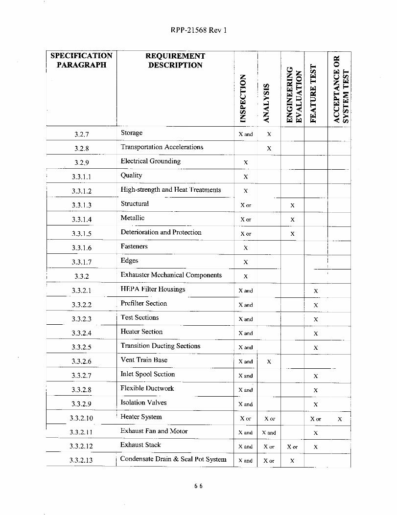
RPP-21568 Rev 1
SPECIFICATION REQUIREMENT aPARAGRAPH DESCRIPTION
z zo ^, W
W a ^a aWp Ud C7d ri
ww ¢
3.2.7 Storage x and X
3.2.8 Transportation Accelerations x
3.2.9 Electrical Grounding x
3.3.1.1 Quality X
3.3.1.2 High-strength and Heat Treatments x^_.._ - --- -
3.3.1.3 Structural X or X
M lli3.3.1.4 eta c x or X
3.3.1.5 Deterioration and Protection x or X
3.3.1.6 Fasteners--
x
3.3.1.7 Edges XI-- -
3.3.2 Exhauster Mechanical Components x
3.3.2.1 HEPA Filter Housings X and X
3.3.2.2 Prefilter Section X and X
3.3.2.3 Test Sections x and X_
3.3.2.4- -
Heater Section X and-^
X
3.3.2.5 Transition Ducting Sections X and X
3.3.2.6 Vent Train Base X and X
3.3.2. 7 Inlet Spool Section X and X
3,3,2.8 Flexible Ductwork x and X
3.3.2.9 Isolation Valves x and X
3.3.2.10 Heater System x or x or x or z
3.3.2.11 Exhaust Fan and Motor X and X and X
3.3.2.1 2 Exhaust Stack x and X or X or X
3 . 3.2.13 Condensate Drain & Seal Pot System X and X or X
66
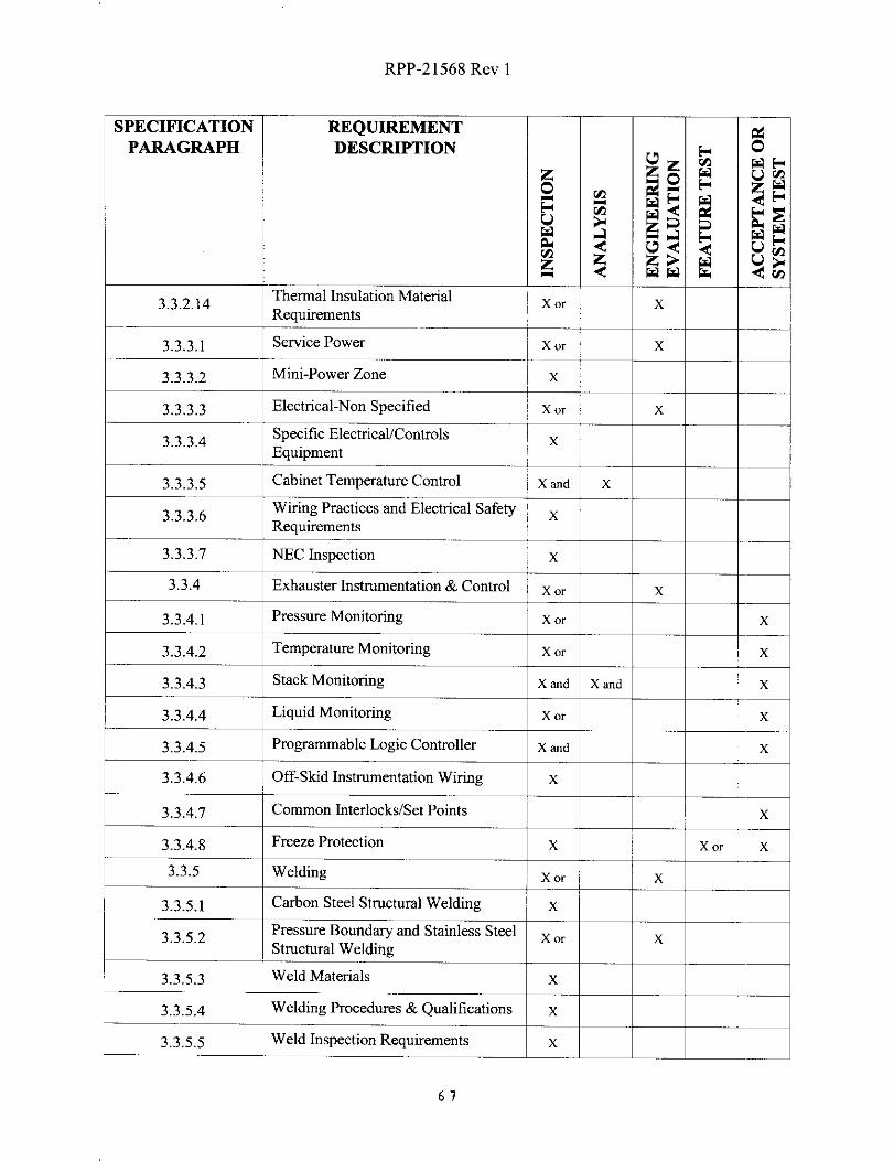
RPP-21568 Rev 1
SPECIFICATION REQUIREMENTPARAGRAPH DESCRIPTION E^ O
ZUzp F UW
O rA
C^w a ^^7 H aww l
z ^ ww w d^+
3.3.2.14Thermal Insulation Material x or xRequirements
3.3.3.1 Service Power X or X
3.3.3.2 Mini-Power Zone x
3.3.3.3 Electrical-Non Specified x or X
3.3.3.4Specific Electrical/Controls
-Equipment
-- ^3.3.3.5
--,Cabinet Temperature Control X and
-X
3.3.3.6Wiring Practices and Electrical Safety xRequirements
3.3.3.7 NEC Inspection x
3.3.4 Exhauster Instrumentation & Control x or X
3.3.4.1 Pressure Monitoring x or x
3.3.4.2 Temperature Monitoring x or x
3.3.4.3 Stack Monitoring X and X and X
3.3.4.4 Liquid Monitoring x or x
3.3.4.5 Programmable Logic Controller X and X
3.3.4.6 Off-Skid Instrumentation Wiring x
3.3.4.7 Common Interlocks/Set Points x
3.3.4.8 Freeze Protection X x or X
3.3.5 Welding Xor X
3.3.5.1 Carbon Steel Structural Welding x
3.3.5.2Pressure Boundary and Stainless Steel X or XStructural Welding
3.3 . 5.3 Weld Materials x
3.3 .5.4 Welding Procedures & Qualifications x
3.3.5.5 Weld Inspection Requirements x
67

RPP-21568 Rev 1
SPECIFICATION REQUIREMENTPARAGRAPH DESCRIPTION
Z z W U
WUZ
^ ^ W W W U- d
3.3.5.6 Workmanship x
3.3.5.7 Additional Welding Requirements x
3.3.6 Cleanliness x
3.3.7.1 Nameplates/Labels x
3.3.7.2 Identification Tags & Numbers x
3.3.7.3 Labeling x
3.3.8 Painting & Coating x
3.3.9 Human Engineering X or X
3.3.9.1 Noise Levels x
3.3.10 Drawings X
4.1. 1 Power System Testing x
Rotating Equipment Balancing &4.1.2 Vibration Criteria x or j X
4.1.3 Filter Housing Testing-^-
x or X
4 1 4Exhaust Fan & Exhaust Train Flow
X. .Testing
4.1.5 Heat Trace Check x
4.1.6 Interlock Alarm Check x
4.1.7 Glycol Heater Check
S k
x
4,1.8
4.1.9
tac Pressure Decay Test
Record Sample Filter Holder Leak I
x
^ XTest ^-
68

RPP-21568 Rev 0
5.0 PROJECT MANAGEMENT
5.1 DESIGN
5.1.1 CONCEPTUAL DESIGN
The seller shall complete a conceptual design in accordance with the requirementsof this specification.
This task shall consist of conceptual design identifying design features that drivethe system cost and manufacturing complexity, interfaces, layouts, andappropriate analyses for all systems/components. The conceptual design shalladdress all of the specification requirements; verification testing and technicalissues shall be identified and evaluated in a conceptual design review and report.The conceptual design task shall include an independent oral review of the designto be presented by the seller at the buyer's facility.
5.1.1.1 Conceptual Design Report
The conceptual design summary report shall include, as a minimum, thefollowing:
• Layout drawings, or arrangement of major component drawings
• Design assumptions and rationale
• Draft assembly drawings showing major items, subassemblies, andestimated component weights.
• Manufacturer's certification of components for explosive atmosphereoperation. This includes all components in contact with exhaustairstream with exception to the CAM, sample flow control valves andsample vacuum pumps.
• Fan performance curves
• Sellers QA Program showing compliance with ASME NQA-1
• Design feature selection rationale, preliminary calculations of seismic
analyses and analyses supporting concept selection. Features
incorporated for leak-check, lifting and handling, etc. Preliminary
interface control documentation that identifies all required interfaces.
69
RPP-21568 Rev 0
5.1.2 DEFINITIVE DESIGN
This effort will include the detailed design of the Exhauster System and allassociated hardware. The seller shall be responsible for all design activitiesrequired to complete all design documentation and analyses, including detail andassembly drawings in sufficient detail to determine interfaces, assembly, anddisassembly sequences. The drawing shall include section views that showsystem details. Structural and seismic analyses will be completed and provided todemonstrate that the chosen design(s) can withstand the load conditions.
The definitive design must be reviewed and approved by the buyer beforefabrication can be initiated. The buyer will review and approve the preliminaryDefinitive Design Report (DDR), and the seller shall successfully complete aindependent oral design review at the buyer's facility with completion of actionitems to the buyer's satisfaction prior to initiation of fabrication. The buyer willreview the release of long lead manufactured items on a case by case basis.
5.1.2.1 Definitive Design Report (DDR)
The seller shall furnish the buyer a final DDR that demonstrates that theseller's design satisfies all the requirements of this specification. As aminimum, this report shall contain, but is not limited to, all the design andsupporting analyses conducted, quality assurance (QA) requirements,testing methods and or analysis of materials, lifting and handling analyses,the acceptance criteria for tests, and all results of completed tests.Identification of all manufacturing equipment and processes,manufacturing tooling, applicable QA inspection requirements, andequipment calibration results shall also be contained in a separate datapackage that shall accompany the final DDR.
Calculations shall meet buyer supplied procedures and be organized in thefollowing order:
a) Objectiveb) Design inputs (criteria and source, given/known data, assumptions,
methods used, computer programs used, reference sources)c) Calculationsd) Findings and conclusions
Calculations and drawings shall be stamped by a licensed engineer of the
appropriate discipline. The stamp shall be recognized by the Washington
State Professional Engineers Department.
70

RPP-21568 Rev 0
The DDR shall include legible, reproducible copies of inspection/testreports. The report(s) shall include the following:
a) Identification of the applicable inspection and/or test procedureutilized.
b) Resulting data for all characteristics evaluated, as required by thegoverning inspection/test procedure.
c) Traceability to the item inspected/tested, (i.e., serial number, partnumber, lot number, etc.).
d) Signature of the seller's authorized representative or agency thatperformed the inspectionsltests.
e) The seller shall provide a legible/reproducible certification ofcompliance (C of Q. The C of C shall be signed by the seller'sauthorized representative. This C of C shall, as a minimum:
1) Identify the appropriate buyer purchase order number underwhich the material, equipment, item, or service is beingsupplied.
2) Provide traceability by means of positive identification fromthe material, equipment, item, or service to the C of C. Thecertificate of compliance shall be signed or otherwiseauthenticated (e.g., initialed, stamped) by a person who isresponsible for this quality assurance function and whosefunction and position are described in the supplier's quality
assurance program.
3) Identify the specific procurement requirements met by thematerial, equipment, item or service supplied, such as codes,standards, and other applicable specifications. Theprocurement requirements identified shall include anyapproved changes, waivers, or deviations applicable to thesubject material, equipment, item, or service.
4) Identify any procurement requirements not met, together with
an explanation and means for resolving the non-conformances.
In addition, this report shall contain, but is not limited to, the
3 1

RPP-21568 Rev 0
documentation listed in Table 5-1.
TABLE 5-1 DEFINITIVE DESIGN REPORT DOCUMENTATION
DOCUMENTATION ITEM DOCUMENT REQUIRED
Design Design documentation applicable to the exhauster unitfabrication and testing as required by ASME AG-1, N509„ andN510, including the applicable sections thereof identifiedthroughout this specification.
ASME AG-1 design verification matrix.
Documentation to certify that stack design complies with ANSIN13.1 and that the CAM accuracy meets ANSI N42. 18 atsample airstream temperatures. This includes testreports/results qualifying sampling location per themethodology described in ANSI N13.1, Table 4.
Design AnalysisCalculations, Acceptance Test Report or Qualification TestData supporting assembly seismic qualification.
Acceptance Test Reports or Qualification Test Data supportingaerosol testing (ASME AG-1 or ASME N5 10, section 10)during shake table test.
Calculations, Acceptance Test Report or Qualification Test
Data supporting assembly induced loading qualification.
Airstream heater design supporting calculations including
psychometric requirements and heat transfer.
Fan calculations and curve including static pressurerequirements.
Seal pot drainage calculations including pot size and drainageinto seal pot when fan is operating. These calculations shallinclude both gravity drain operations, and the maximum headavailable at the condensate pump discharge line flangeconnection.
Exhaust stack design support calculations including size andsampling analysis.
Sampling system vacuum pump sizing calculations.
Record sample filter holder leak rate.
Exhauster assembly design life evaluation.
Electrical and instrument cabinet temperature controlcalculations including both summer and winter analysis.
72
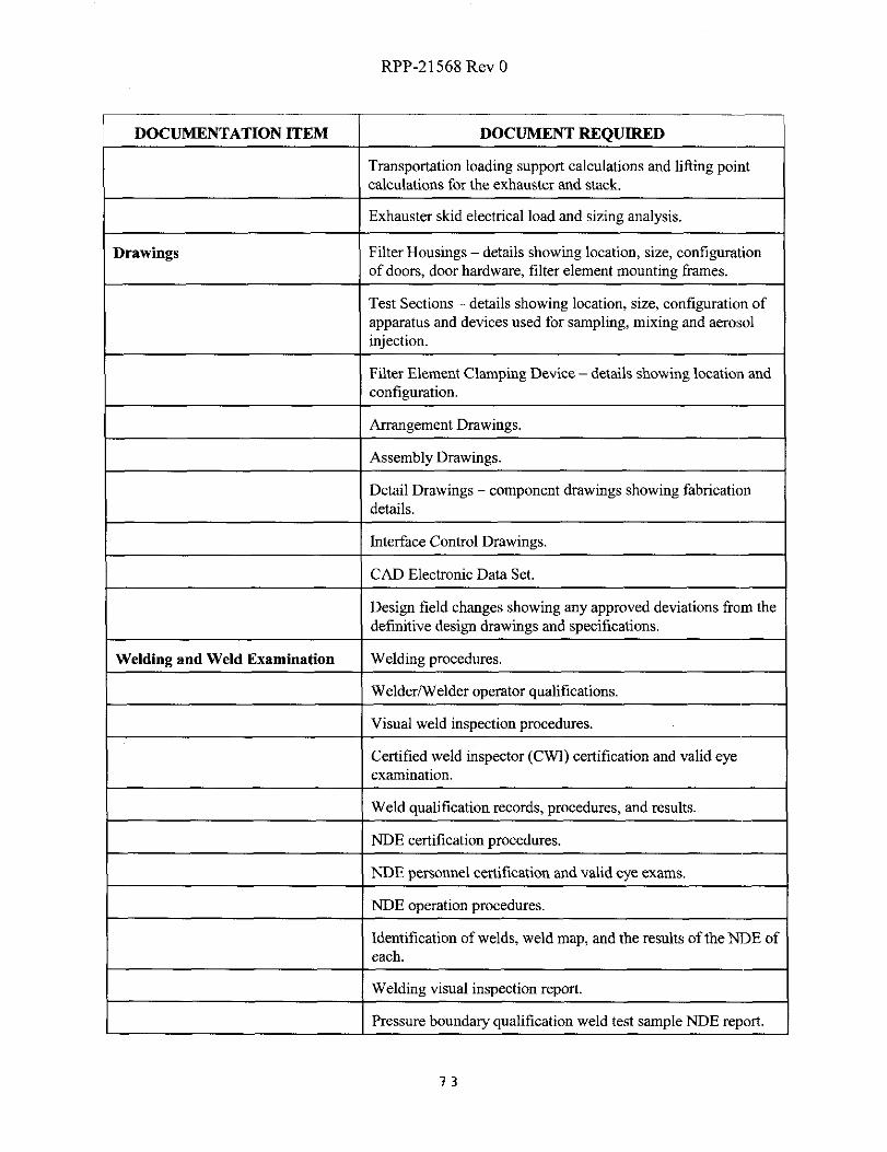
RPP-21568 Rev 0
DOCUMENTATION ITEM DOCUMENT REQUIRED
Transportation loading support calculations and lifting pointcalculations for the exhauster and stack.
Exhauster skid electrical load and sizing analysis.
Drawings Filter Housings - details showing location, size, configurationof doors, door hardware, filter element mounting frames.
Test Sections - details showing location, size, configuration ofapparatus and devices used for sampling, mixing and aerosolinjection.
Filter Element Clamping Device - details showing location andconfiguration.
Arrangement Drawings.
Assembly Drawings.
Detail Drawings - component drawings showing fabricationdetails.
Interface Control Drawings.
CAD Electronic Data Set.
Design field changes showing any approved deviations from the
definitive design drawings and specifications.
Welding and Weld Examination Welding procedures.
Welder/Welder operator qualifications.
Visual weld inspection procedures.
Certified weld inspector (CWI) certification and valid eyeexamination.
Weld qualification records, procedures, and results.
NDE certification procedures.
NDE personnel certification and valid eye exams.
NDE operation procedures.
Identification of welds, weld map, and the results of the NDE ofeach.
Welding visual inspection report.
Pressure boundary qualification weld test sample NDE report.
73

RPP-21568 Rev 0
DOCUMENTATION ITEM DOCUMENT REQUIRED
Filter element holding frame weld NDE report.
Inspection/TestProcedures/Reports
Exhauster system Acceptance Test Procedure (ATP).
Exhauster system Acceptance Test Report (ATR).
Visual inspection check list per ASME AG-1 or ASME N5 10section 5.
Airflow distribution test per ASME AG-1 or ASME N510section 8.
Air-aerosol mixing uniformity test per ASME AG-1 or ASMEN510 section 9.
Filter element holding frame decay leakage test per ASME AG-1 or ASME N510 section 7.
Assembly decay leakage test per ASME AG-1 or ASME N5 10section 6.
Exhaust fan and exhaust train flow testing.
Rotating component balancing reports.
Record sample filter holder leak test reports.
Test procedure demonstrating that stray electromagneticradiation/noise (i.e. RF, cellular phones, power) does notinterfere with the control circuit function per Section 3.2.5.2.
Leak test procedure for the stack sampling system in accordancewith ANSI N13.1, section 6.9
QA Sellers program shows compliance with ASME NQA-1.
All NCR's will be submitted.
Supplier certification and release completed.
C of C stating seller has met requirements of this specification.
C of C stating NDE requirements of this specification havebeen met.
Objective evidence showing procured assemblies (i.e., gages,valves, etc....) were provided from the original equipmentmanufacture and received at sellers facility in an acceptablecondition to perform its intended function.
System Procedures/Manuals Operation procedure/manual.
74

RPP-21568 Rev 0
DOCUMENTATION ITEM DOCUMENT REQUIRED
Maintenance/storage procedure.
Spare parts list.
Special handling and loading procedures.
System Equipment Catalog cuts of exhauster assembly components andinstrumentation in organized notebook.
Warranties.
5.2 WORK PLAN
The seller shall ensure all work is consistent with the requirements of the purchase order
terms and conditions, and this specification.
A work plan describing all deliverable dates shall be submitted to the buyer. The workplan must include a complete project schedule. The deliverable schedule must meet theoverall project schedule listed in the request for proposal and/or purchase order.
This schedule will be updated as required for the monthly status reporting. Any changesto the work plan will require written concurrence of the buyer.
5.2.1 MONTHLY STATUS REPORTS
On the fifth working day of the month, the seller shall submit to the buyer asimple summary of accomplishments, upcoming events, issues that requireresolution, and technical and programmatic problems encountered during theprevious month. The monthly input shall be organized according to the seller'swork plan. Included in each monthly report shall be a status schedule for theentire program.
75
RPP-21568 Rev 0
5.2.2 CONTRACT KICKOFF MEETING
A kickoff meeting will be held between the buyer and seller at the seller'smanufacturing location at the time of the contract award. This meeting will focuson the seller's scope, line by line discussions of the specification, deliverables,information transfer, reviews, meetings, reporting, etc.
5.2.3 COMMITMENT TRACKING LIST
The seller shall maintain a listing of all buyer-seller review comments generatedduring the design, fabrication, and testing process. The seller shall track the statusof comment disposition until all comments are satisfactorily incorporated into thedesign or otherwise resolved.
5.3 FABRICATION
The fabrication includes equipment procurement, component fabrication, assembly andfabrication inspection. The seller shall be responsible for the manpower, facilities, andequipment to complete purchasing, fabrication, assembly, checkouts, and delivery of theExhauster System. The seller shall also manage the fabrication activities, which includecreating and maintaining production scheduling, and the quality assurance plan (QAP).Manufacturing activities include manufacturing and documentation for componentfabrication, assembly, purchasing, storage, and spare parts. Additional manufacturingactivities include transportation and packaging, tooling design, tooling documentation,
and fabrication as required. Engineering support includes design documentation, designanalysis, logistics, engineering support, and configuration management. The seller shallprovide all special tools and calibrated equipment necessary for assembly, operation, andmaintenance.
5.3.1 GENERAL REQUIREMENTS
a) Distributors furnishing items on this purchase order to the seller shall obtainsaid items directly from the original manufacturer of the items. Thedistributor shall provide legible and reproducible documentation to the sellerthat provides objective evidence that the items were provided by the originalmanufacturer. These may include the purchase order to the originalmanufacturer, shipping documentation, or manufacturer invoice; each ofwhich identifies the items obtained from the original manufacturer.
b) The seller shall submit, with or prior to item shipment, a recommended spareparts list. The list shall provide the name and address of the original supplier
76

RPP-21568 Rev 0
of the replacement part, and the part's drawings, specification, or catalogidentity including applicable change or revision information.
c) Seller shall warrant that all items furnished under this purchase order aregenuine (i.e., not counterfeit) and match the quality, test reports, markingsand/or fitness for use required by the purchase order.
d) Any materials furnished as part of this purchase order which have beenpreviously found to be suspect/counterfeit by the buyer or any U.S.Government agency shall not be accepted.
e) Further information about suspect/counterfeit products may be obtaineddirectly from the Department Of Energy.
5.3.2 SUBCONTRACTOR IDENTIFICATION
The seller shall include a list of subcontractors if required for specializeddesign/analysis or fabrication tasks. The seller shall provide relevant inform ationregarding the experience, management and personnel. The seller's subcontractorwill be bound by the same welding, inspection, and submittal requirements as theseller.
5.3.3 FABRICATION AND INSPECTION PLAN
The seller shall provide to the buyer for review and approval a Fabrication andInspection Plan to include a sequential listing of major fabrication steps and theassociated inspections required for compliance with this contract. The seller'sfabrication plan shall identify fabrication activities, with a production schedule,and manufacturing activities such as tooling design and fabrication. The qualityassurance plan shall define the approach for manufacturing, documentation forcomponent fabrication, assembly, purchasing, storage, spare parts, control ofnonconforming items, and configuration management. The fabrication plan willdefine all inspect hold points and critical items or features as defined from thedesign to be inspected. The buyer shall reserve the right while reviewing this planto identify in writing to the seller inspection or testing activities to be witnessedby the buyer representative. The buyer retains the right to witness any and allcritical items/feature inspections. The seller shall notify the buyer no later than 10working days prior to any specified witness points.
77

RPP-21568 Rev 0
5.4 TESTING AND EVALUATION
The exhauster assembly shall be shop tested at the seller's facility as a complete unit priorto shipment. A buyer's representative shall witness and accept final shop test prior toshipment. The acceptance test will serve as design verification. Acceptance testing willdemonstrate all alarm circuits, the ability of the exhauster to operate continuously overthe full range of design basis flow rates, and the capability of monitoring instruments atminimum and maximum flow rates.
The seller shall submit all analyses and engineering evaluations required by theverification matrix to the buyer for review and approval.
5.4.1 ACCEPTANCE TEST PLAN
The acceptance test plan shall include the test objectives, schedules for testing,test matrix, test acceptance criteria, test facilities, special test equipment,calibrated instrumentation, and data reduction requirements, if appropriate. Allrequired testing instrumentation shall be provided by the seller unless otherwisenoted. Any special test equipment required for testing shall also be identified andprovided by the seller. Special test equipment will be designed and developed bythe seller as required to complete acceptance and verification testing. The buyerwill review and approve the acceptance test plan.
The seller shall identify in his plan if any feature testing required by theverification matrix has been previously completed for another program or activity.This use of similar or previously collected data that directly applies to thespecification requirement(s) will be allowed as approved by the buyer.
5.4.2 ACCEPTANCE TEST PROCEDURE (ATP)
The seller shall submit an acceptance test procedure (ATP) that includes testsidentified in the verification matrix to the buyer for approval. The seller isresponsible for all equipment required for the ATP. The seller shall notify thebuyer two weeks prior to starting the ATP. The seller shall assure the buyer thatall of the tests can be performed satisfactorily before scheduling the official ATP.At conclusion of the testing a NEC certification sticker shall be applied to theexhauster.
5.4.3 ACCEPTANCE TEST REPORT (ATR)
The seller shall assemble the results of the acceptance tests into an ATR to be
78

RPP-21568 Rev 0
submitted as part of the record package. The ATR shall summarize the results ofthe acceptance tests and shall contain the test results and test exceptions with theirdispositions.
5.5 OPERATION/MAINTENANCE PROCEDURES
5.5.1 OPERATION PROCEDURE/MANUAL
The seller shall provide an Exhauster System operating procedure/manual. Thebuyer will review and approve the operation procedure/manual. The operationsprocedure/manual shall provide detailed information for operation of allequipment including one-line diagrams for electrical, piping and instrumentation.The seller's procedure/manual shall include sketches as appropriate utilizing,isometric figures to the greatest extent possible. The operations procedure/manualshall include trouble shooting of all systems and discuss all control system faultsand appropriate operator actions for those faults. The procedure/manual shall bebound in a binder with weather resistant page protection.
5.5.2 MAINTENANCE/STORAGE PROCEDURES
The maintenance procedure shall include information for the maintenance, repair,assembly, and disassembly of the Exhauster System and all ancillary equipment.The procedure may refer to manufacturers manuals for the servicing ofcommercial items and must include these manuals and instructions as part of themaintenance procedure. The seller's manual shall identify removal/assemblysequences, lubrication schedules, isometric sketches of equipment and weights,lifting points and approximate centers of gravity, identification of consumableitems (such as seals/gaskets), and the use of special tooling for the procedure.
The seller shall provide a master list of all equipment requiring maintenance. Thelist shall include the manufacturers' recommendations, instructions, and intervalsfor maintaining the equipment. Particular emphasis shall be placed on the type ofmaintenance (preventive, predictive, or corrective) and the manufacturers' specificrecommendations. The maintenances procedure shall apply the principles ofreliability-based analysis for maintenance task identification for components thatare worthy of the rigors of Reliability Centered Maintenance (RCM) analysis.The buyer will review and approve the maintenance procedures.
Seller shall provide a list of recommended spare parts, identifying each specificsubassembly at which it applies. Seller shall indicate the minimum recommendedinventory of the spare parts for installation, start-up, and maintenance for a one (1)year period based on 8700 hours of operation per year. Seller shall state whether
79

RPP-21568 Rev 0
the recommended spare part is stock item or a special item, and shall furnish nameand location of the nearest supplier.
The seller shall also provide a storage procedure for the Exhauster System. Thestorage procedure shall identify if any special storage precautions are required forwinter, or summer storage and how to protect the electronics and control systemsfrom damage during storage. The storage procedure shall also ensure rotatingequipment is protected during storage. The buyer will review and approve thestorage procedures.
5.6 SUBMITTALS
Table 5-2 contains the submittal schedule for the contract and the following sectionsprovide a description of the required submittals. Four copies of submittals shall beprovided if not otherwise specified. All submittals shall be in English. Electronic copiesof submittals will be provided whenever practical
5.6.1 SUBMITTALS REQUIRED WITH PROPOSAL
5.6.1.1 Preliminary List of Drawings and Documentation
The seller shall provide a preliminary list of drawings and documentationthat will be provided as part of the contract. Typical drawings include:
• System Schematics or P&ID
• Assembly Drawings
• Subassembly Drawings
• Connection Diagrams
• Wire Run Lists
• One Line Electrical Diagrams
• Elementary Diagrams
• Instrument Loop Diagrams
• Outline Drawings
• Panel Schedules
• Instrument Set Point/Program Set-Up List
5.6.1.2 Quality Assurance Program
The seller shall provide a copy of their Quality Assurance Plan.
5.6.1.3 Identification of Subcontractors
The seller shall provide a list of proposed subcontractors.
80

RPP-21568 Rev 0
5.6.1.4 Preliminary Welding and NDE Submittals
Qualified Welding and NDE Procedures and Certified ProcedureQualification Records shall be submitted with the proposal by the sellerfor each type of weld and each characteristically different welding joint.
5.6.1.5 Preliminary Schedule
The seller shall provide a schedule assuming that the start date is thereceipt of the order. The schedule shall contain a summary of activitiesrequired to design, fabricate, test, and ship the exhauster System.
5.6.2 SUBMITTALS REQUIRED AFTER RECEIPT OF ORDER
5.6.2.1 Work Plan
The seller shall submit a work plan per Section 5.2 of this specification.
5.6.2.2 Detailed Schedule
The seller shall provide a detailed schedule showing the activities required
to design, fabricate, test, and ship the Exhauster System.
5.6.2.3 Written Status Reports
The seller shall provide written status reports on a monthly basis duringthe execution of this contract. The status reports shall summarize theactivities completed during the last reporting interval and provide schedulestatus (e.g. schedule slippage).
5.6.3 SUBMITTALS REQUIRED PRIOR TO FABRICATION
5.6.3.1 Conceptual Design Report
The seller shall submit a conceptual design report per Section 5.1.1 of thisspecification.
5.6.3.2 Preliminary Definitive Design Report
The seller shall submit a preliminary definitive design report per Section5.1.2 of this specification. This report shall consist of all items listed inTable 5-1 that can be completed prior to fabrication. Report to include alldesign analysis and fabrication drawings.
81
RPP-21568 Rev 0
5.6.3.3 Fabrication and Inspection Plan
The seller shall submit a fabrication and inspection plan per Section 5.3.3of this specification.
5.6.3.4 Welding and NDE
Qualified Welding Procedures and Certified Procedure QualificationRecords shall be submitted by the seller for each type of weld and eachcharacteristically different welding joint listed in the plan for welding andNDE.
Certified records of qualified personnel who will perform or verify thewelding or NDE, if not already provided with the proposal, shall besubmitted by the seller.
5.6.3.5 Preliminary Operation and Service Procedures/Manuals
The seller shall provide a preliminary version of the procedures/manualsrequired in Section 5.8 of this specification.
5.6.3.6 Other Information and Design Data to Evaluate Design
The seller shall submit sufficient information and design data that isnecessary to support proposed design.
5.6.4 AUTHORIZATION TO START FABRICATION
The seller shall not start fabrication until written authorization has been receivedfrom the buyer.
5.6.5 SUBMITTALS REQUIRED TO START TESTING
5.6.5.1 Acceptance Test Plan
The seller shall submit to the buyer the Acceptance Test Plan per Section5.4.1 of this specification.
5.6.5.2 Acceptance Test Procedure (ATP)
The seller shall submit to the buyer the ATP per Section 5.4.2 of thisspecification.
82

RPP-21568 Rev 0
5.6.6 SUBMITTALS REQUIRED FOR CONTRACT COMPLETION
The seller shall not ship the Exhauster System and ancillary hardware until alltests and inspections have been performed and the documentation data package iscomplete and approved by the buyer. A separate data package (consisting o1'thedocuments identified in this section) shall be provided for each exhauster unitpurchased. The documents shall be traceable to the exhauster unit (e.g., containthe exhauster unit's identification number). All software used/delivered shall beregistered in the buyer's name prior to turnover of the exhauster.
5.6.6.1 Final Design Analysis Report
The seller shall submit a Final Design Analysis Report that includes allitems listed in Table 5-1 as a minimum.
5.6.6.2 As-Built Drawings and Specifications
The seller shall deliver to the buyer eight (8) copies of the final fabricationlevel as-built drawings and specifications accurately depicting the productdelivered. Drawings shall include dimensional layouts, dimensionedsubassemblies, dimensioned component details (if not included onmanufacturers' cut sheets), flow and electrical diagrams, material andfastener sizes, descriptions, weld symbols and notes. The designer'sname, responsible engineer's name, bill of materials, and drawing numbersshall appear on the index (cover sheet).
Drawing size shall be per ANSI Y14.1. Bills of material on drawings shallinclude quantity, manufacturer, material type, electrical characteristics,size, and general descriptions. All component parts shall refer toapplicable material specifications, such as the Military, ASME, ASTM,Federal, or other specifications. As-Built Drawings shall be verified inaccordance with Quality Assurance Program Controls of Section 5.9.2prior to submittal, and shall be in accordance with buyer supplied drawingprocedures.
Drawings shall be prepared using AutoCAD compatible drafting software.A copy of all as-built drawing files (one of which shall be an electronicAutoCAD release 12, 13, or 14 compatible file format) shall be includedin the final drawing package. Drawings shall use the ROMANSAutoCAD text font and the minimum text height shall be 1/8 inch.
83

RPP-21568 Rev 0
5.6.6.3 Final Calculations
Reviewed and approved calculations shall be legible and prepared on 8'h"by 1 P' sheets with all pages numbered and bound in hard cover binder.Calculations shall be organized as described above in Section 5.1.2. 1. Thecalculations listed in Table 5-1 under "Design Analysis" shall be provided
as a minimum.
5.6.6.4 Inspection & Testing Reports
Inspections, examinations, and testing activities, including the completedATP and ATR as described in Section 5.4, shall be documented and thedocumentation delivered before shipment of the product. InspectionReports shall provide actual inspection results, specifying what wasinspected, who inspected it, the characteristics inspected, and theacceptance criteria.
5.6.6.5 Certified Test Reports
The seller shall provide the buyer with Certified Material Test Reports for
the structural materials, tubing, fittings, and material used in weldingapplications, as well as a certificate of compliance for the system.
Certified Material Test Reports shall list all specification numbers(including revision status) to which the material is required toconform. Each certification shall contain the substance of thefollowing statement; "It is hereby certified that the material identifiedherein conforms to the listed specifications."
The Certificate of Compliance shall describe the product and identifycontract requirements met, including reference to codes, standards,specifications, (including revision status), written change orders andany buyer-approved Contractor Non-Conformance Requests. TheCertificate of Compliance shall describe the quality assurance fuictionand position of the person attesting to its accuracy.
5.6.6.6 Operation and Service Procedures/Manuals
The seller shall provide the procedures/manuals required in Section 5.5,Operations/Maintenance Procedures, of this specification.
5.6.6.7 Calibration Reports
The seller shall provide instrument factory calibration data sheets and
84
RPP-21568 Rev 0
calibration reports for the measuring and test equipment provided with theproduct. The reports shall contain the parameters calibrated, acceptancecriteria and the actual calibration results. The seller shall certify that thesupplies tendered for acceptance have been calibrated using standardswhose calibration is (a) traceable to the NIST (or other nationallyrecognized standards acceptable to the buyer), (b) derived for acceptedvalues of natural physical constants, or (c) derived by the ratio type of self-calibration techniques.
5.6.6.8 Packaging And Shipping Plan
The seller shall submit the packaging and shipping plan required inSection 5.12 of this specification.
5.6.6.9 Records Maintenance, Control, and Disposition
The seller shall collect, identify, and maintain originals of recordsgenerated for this contract and included in Table 5-2, Deliverables andSchedule. Where contract records include generic procedures such aswelding or NDE procedures, reproducible copies may be submitted insteadof originals if validated.
Where submittals are required during the term of the contract for thebuyer's review, copies shall be submitted. Within 10 days of contractcompletion, however, the originals (or validated reproducible copies) ofthe records shall be delivered to the buyer at a location specified by thebuyer's Contract Specialist. The originals of records which are not ofreproducible quality shall be so identified.
All records shall be protected against damage, deterioration, loss orunauthorized use. All records shall meet the following standards:
1) Signed, initialed, or otherwise authenticated and dated.Handwritten signatures are not required if a statement from thereporting individual or organization identifies the record.
2) Traceable to the item or activity.3) Legible, accurate, reproducible, and complete.4) Corrected, if necessary, by the record originator, who shall
mark out the incorrect information with a single line, enter thecorrect information and then initial and date the correction. Ifthe reason for the change is not obvious, then it must be stated.
5.7 DOCUMENT CONTROL
85
RPP-21568 Rev 0
5.7.1 CHANGES TO BUYER'S DOCUMENTS
Changes to buyer's purchase order requirements will be documented byissuance of buyer's Purchase Order Modification that will be transmittedto seller for determination of impact on cost and schedule.
5.7.2 CHANGES TO SELLER'S DOCUMENTS
Changes to seller's approved design shall be controlled by change controlprocess approved by buyer. Seller shall notify buyer of proposed change.Detailed description of change, including justification for change, shall beincluded.
5.7.3 OWNERSHIP OF DESIGN MEDIA
At contract closeout, all contract data (e.g. prints, computer files,procedures, vendor data, etc.) shall become the property of the buyer. Thebuyer shall have unlimited rights to use, duplicate, disclose to others, ormodify any part or all of the supplied contract data.
5.8 CORRESPONDENCE
The seller shall deliver legible copies, as required by document submittal. Theseller shall send these and all other documents to:
CH2M HILL Hanford GroupP.O. Box 1500Richland, WA 99352
ATTN: (Buyer's name and MSIN as it appears on the purchase order)
5.9 QUALITY ASSURANCE PROGRAM
The seller shall have in place a Quality Assurance Program (QAP) that satisfies thecriteria of ASME NQA-1 as specified in the contract. The seller shall furnish a matrixthat cross-references the plan with the corresponding requirements listed.
5.10 PRE-AWARD SURVEYS
A pre-award survey will be conducted by the buyer on each of the sellers who aredetermined to be in the competitive range. This survey shall be scheduled by the buyer'srepresentative and shall encompass the seller's and identified major subcontractors'
86

RPP-21568 Rev 0
technical, quality assurance, production, or financial capability.
5.11 RIGHT OF ACCESS
The seller shall permit and make arrangements in writing for the buyer to enter all areasof the seller's or subcontractor's facilities associated with producing the exhausterequipment, for the purpose of examining the materials, equipment, processes, andprocedures employed during the design, fabrication, assembly, testing, and shipment ofthe equipment. The seller shall permit photograph and video records by the buyer in theseller's facilities associated with producing the exhauster equipment.
5.12 A SUBMITTAL COMPLIANCE REQUIREMENTS
The seller shall comply with the inspection and test plans and welding and Non-Destructive Examination (NDE) procedures and plans submitted and approved by thebuyer and utilize, except as authorized by the buyer in writing, only those qualifiedpersonnel to perform or verify the special processes and operations for whom certifiedrecords were reviewed and approved by the buyer.
5.13 PACKAGING AND SHIPPING PLAN
The seller shall recommend the preferred transportation method to provide the bestprotection of the Exhauster System during transit. The final plan shall be completed atthe conclusion of the design with approval by the buyer.
5.13.1 CLEANING, PACKAGING AND SHIPPING
The seller shall submit for buyer approval a packaging and shipping plan whichcontains seller's procedures for packaging, marking, and shipping the exhauster tothe buyer. Buyer approval of the plan is required before packaging and shipment.If a special type of transportation to protect the electronics is required, or specialhandling devices are needed for assembly or installation of equipment, thosedevices shall be part of the seller's package and identified as special equipment.
Each item of equipment shall be packaged to eliminate damage due to outsidestorage for up to one year, or damage due to shipping and handling by forklift orhoist. Packages or skids shall be marked at the seller's site with the buyer'spurchase order number. Equipment shall be dismantled only as necessary forshipment, and dismantled equipment shall require the approval of the buyer. Eachcomponent to be shipped loose shall be marked at the seller's site with the buyer's
87

RPP-21568 Rev 0
purchase order number and the identifying number of its respective component.Lift points or centers of gravity shall be marked on shipping crates.
Filter housings shall be packaged and shipped in accordance with therequirements of ASME N509 from the manufacturer's plant to the seller's point ofinstallation.
Material not shipped in a weatherproof vehicle shall be protected from theweather in a manner acceptable to the buyer. The shipping procedures shalldefine the method of protecting exhauster components from the weather.
88
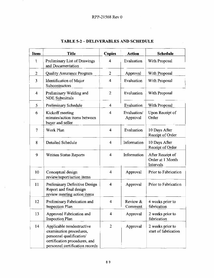
RPP-21568 Rev 0
TABLE 5-2 - DELIVERABLES AND SCHEDULE
Item Title Copies Action Schedule
1 Preliminary List of Drawings 4 Evaluation With Proposaland Documentation
2 ualit Assurance Program 2 A roval With Pro osal
3 Identification of Major 4 Evaluation With ProposalSubcontractors
4 Preliminary Welding and 2 Evaluation With ProposalNDE Submittals
5 Preliminary Schedule 4 Evaluation With Pro osal
6 Kickoff meeting 4 Evaluation/ Upon Receipt ofminutes/action items between Approval Order
buyer and seller
7 Work Plan 4 Evaluation 10 Days AfterReceipt of Order
8 Detailed Schedule 4 Information 10 Days AfterReceipt of Order
9 Written Status Reports 4 Information After Receipt ofOrder at 1 MonthIntervals
10 Conceptual design 4 Approval Prior to Fabrication
review/report/action items
11 Preliminary Definitive Design 4 Approval Prior to FabricationReport and final designreview meeting action items
12 Preliminary Fabrication and 4 Review & 4 weeks prior toIns ction Plan Comment fabrication
13 Approved Fabrication and 4 Approval 2 weeks prior toInspection Plan fabrication
14 Applicable nondestructive 2 Approval 2 weeks prior toexamination procedures, start of fabricationpersonnel qualification/
L t
certification procedures, and
- personnel certificati on records
89
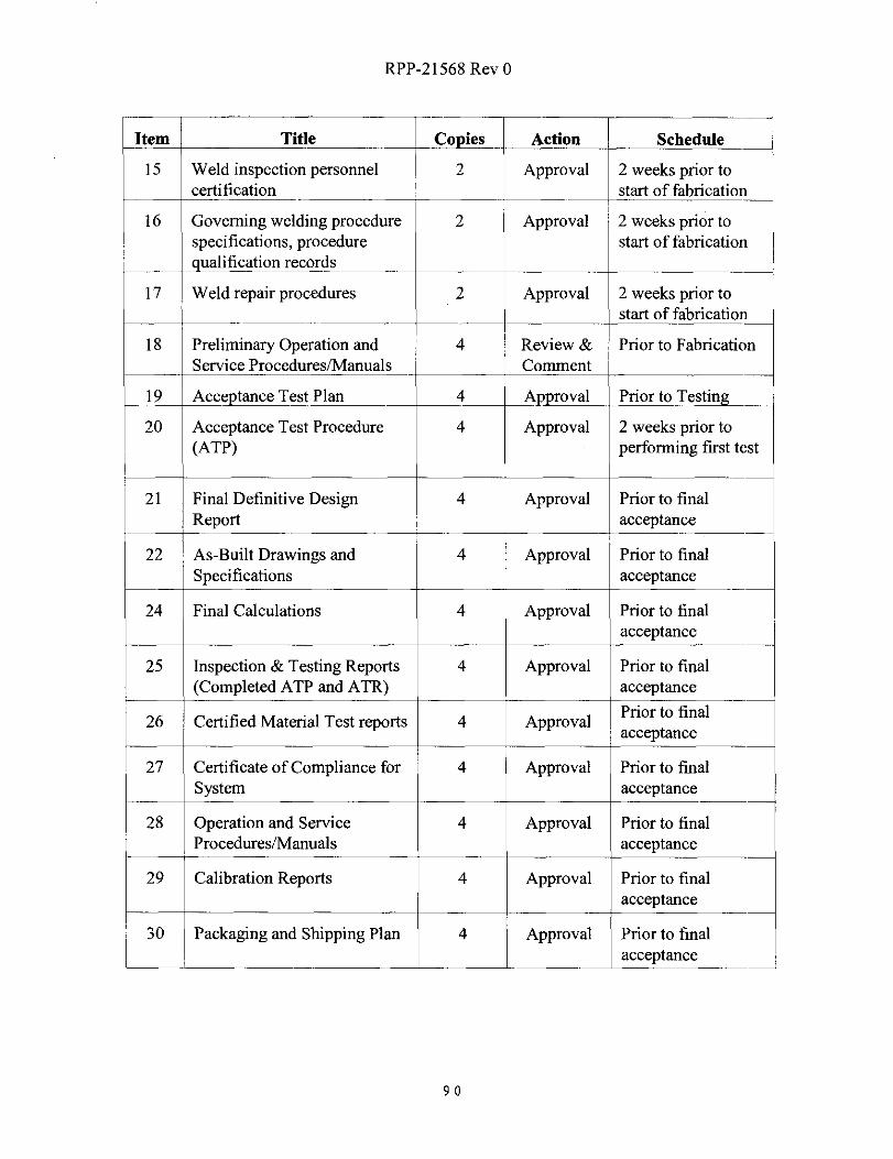
RPP-21568 Rev 0
Item Title Co ies Action Schedule
15 Weld inspection personnel 2 Approval 2 weeks prior tocertification start of fabricatio n
16 Governing welding procedure 2 Approval 2 weeks prior tospecifications, procedure start of fabricationualification records
17 Weld repair procedures 2 Approval 2 weeks prior tostart of fabricatio n
18 Preliminary Operation and 4 Review & Prior to FabricationService Procedures/Manuals Comment
19 Acceptance Test Plan 4 Approval Prior to Testing
20 Acceptance Test Procedure 4 Approval 2 weeks prior to(ATP) performing first test
21 Final Definitive Design 4 Approval Prior to finalReport acceptance
22 As-Built Drawings and 4 Approval Prior to finalSpecifications acceptance
24 Final Calculations 4 Approval Prior to finalacceptance
25 Inspection & Testing Reports 4 Approval Prior to final(Completed ATP and ATR) acceptance
26 Certified Material Test reports 4 ApprovalPrior to finalacceptance
27 Certificate of Compliance for 4 Approval Prior to finalSystem acceptance
28 Operation and Service 4 Approval Prior to finalProcedures/Manuals acceptan ce
29 Calibration Reports 4 Approval Prior to finalacceptance
30 Packaging and Shipping Plan 4 Approval Prior to finalacceptance
90
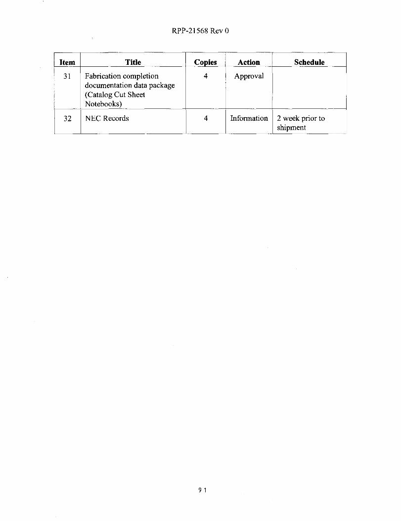
RPP-21568 Rev 0
Item Title Co ies Action Schedule
31 Fabrication completion 4 Approvaldocumentation data package(Catalog Cut SheetNotebooks)
32 NEC Records 4 Information 2 week prior toshipment
91
RPP-21568 Rev 0
APPENDIX A
SUSPECT/COUNTERFEIT FASTENER HEADMARK LIST
92

RPP-21568 Rev 0
APPENDIX B
MECHANICAL COMPONENT DESIGN SKETCHES
93
RPP-21568 Rev 0
APPENDIX C
ELECTRICAL AND INSTRUMENTATION DESIGN SKETCHES
94
RPP-21568 Rev 0
APPENDIX D
STACK MONITORING DESIGN SKETCHES
95

RPP-21568 Rev 0
APPENDIX E
OFF-SKID INSTRUMENTATIONCONNECTION SKETCHES (REF ONLY)
96