chainsaw chain sharpenercdn0.blocksassets.com/...manuals/.../ozccs85wa.pdf · chainsaw chain...
TRANSCRIPT

Chainsaw Chain Sharpener85 WattOperation Manual2 Year Replacement Warranty
OZCCS85WA
To view the entire range visit: www.ozito.com.au1108

Motor: 85 wattInput: 230V ~ 50HzNo load speed: 4,800/minTable/vice angles: 0 – 35° left & rightDisc dimensions: 108 x 3.2mmBore diameter: 23mmSuitable for use withChain pitch sizes: 0.325” and 3/8” Weight: 2.4kg
Features: Bench mounting holesSafety guard
1. Lowering hand piece2. Grinding disc cover3. Depth of grind knob4. Depth of grind locking knob5. Depth of grind pin6. Depth stop platform7. Bench mounting holes8. Sharpener base9. Guide10. Table locking knob
11. Adjustable table12. Table scale13. Guide clamp lever14. Chain stop adjusting knob lock nut15. Chain stop adjusting knob16. Chain (tooth) stop17. Grinding disc18. Grinding disc safety guard 19. Direction of rotation indicator
4
8
11
3
17
13
12
5
6
1
18
2
SPECIFICATIONS - MODEL NO. OZCCS85WA
2
7
910
14
15
16
19

3
TABLE OF CONTENTS
SPECIFICATIONS………………………………………….
TABLE OF CONTENTS…………………………………...
INTRODUCTION………………………………………….
SAFETY INSTRUCTIONS………………………………...
GENERAL………………………………………………….
ASSEMBLY ………………………………………………..
SETTING OF THE SHARPENER………………………...
OPERATION ………………………………………………
MAINTENANCE …………….……………………………
DESCRIPTION OF SYMBOLS……………………………
CONTENTS ……………………………………………….
WARRANTY………………………………………………..
Page 2
Page 3
Page 4
Page 4
Page 5
Page 7
Page 8
Page 10
Page 13
Page 13
Page 14
Page 15

INTRODUCTION
SAFETY INSTRUCTIONS
ELECTRICAL SAFETY
4
Congratulations on purchasing the Ozito ChainsawChain Sharpener. We aim to provide quality tools at anaffordable price. We hope you will enjoy using thisSharpener for many years.
Your Sharpener OZCCS85WA has been designed forsharpening chainsaw chains. This product is intendedfor DIY use only.
Warning! When using mains-powered equipment, basic safety precautions,including the following, should always be followed to reduce risk of fire,electric shock, personal injury and material damage.
Read and understand the manual prior to operating this tool.
Save these instructions and other documents supplied with this tool for future reference.
The electric motor has been designed for 230V and 240V only. Always check thatthe power supply corresponds to the voltage on the rating plate.
Note: The supply of 230V and 240V on Ozito tools are interchangeable forAustralia and New Zealand.
This tool is double insulated in accordance with AS/NZS 3100: 2002;therefore no earth wire is required.
If the supply cord is damaged, it must be replaced by an electrician or a powertool repairer in order to avoid a hazard.
Note: Double insulation does not take the place of normal safety precautions whenoperating this tool. The insulation system is for added protection against injuryresulting from a possible electrical insulation failure within the tool.
Using an Extension Lead
Always use an approved extension lead suitable for the power input of this tool.Before use, inspect the extension lead for signs of damage, wear and ageing.Replace the extension lead if damaged or defective. When using an extension leadon a reel, always unwind the lead completely. Use of an extension lead not suitablefor the power input of the tool or which is damaged or defective may result in a riskof fire and electric shock.

5
GENERAL
!! Warning! Read all instructions. Failure to follow all instructions listed belowmay result in electric shock, fire and/or serious injury. The term “Power Tool”in all of the warnings listed below refers to your mains operated (corded)power tool or battery operated (cordless) power tool.
SAVE THESE INSTRUCTIONS
1) WORK AREA
a) Keep work area clean and well lit. Cluttered and dark areas invite accidents.
b) Do not operate power tools in explosive atmospheres, such as in thepresence of flammable liquids, gases, or dust. Power tools create sparks whichmay ignite the dust or fumes.
c) Keep children and bystanders away while operating a power tool. Distractionscan cause you to lose control.
2) ELECTRICAL SAFETY
a) Power tool plugs must match the outlet. Never modify the plug in any way.Do not use any adapter plugs with earthed (grounded) power tools.Unmodified plugs and matching outlets will reduce risk of electric shock.
b) Avoid body contact with earthed or grounded surfaces such as pipes,radiators, ranges and refrigerators. There is an increased risk of electric shock ifyour body is earthed or grounded.
c) Do not expose power tools to rain or wet conditions. Water entering a powertool will increase the risk of electric shock.
d) Do not abuse the cord. Never use the cord for carrying, pulling or unpluggingthe power tool. Keep cord away from heat, oil, sharp edges or moving parts.Damaged or entangled cords increase the risk of electric shock.
e) When operating a power tool outdoors, use an extension cord suitable foroutdoor use. Use of a cord suitable for outdoor use reduces the risk of electric shock.
3) PERSONAL SAFETY
a) Stay alert, watch what you are doing and use common sense when operating apower tool. Do not use a power tool while you are tired or under the influenceof drugs, alcohol or medication. A moment of inattention while operating powertools may result in serious personal injury.
b) Use safety equipment. Always wear eye protection. Safety equipment such asdust mask, non-skid safety shoes, hard hat, or hearing protection used forappropriate conditions will reduce personal injuries.
c) Avoid accidental starting. Ensure the switch is in the off position beforeplugging in. Carrying power tools with your finger on the switch or plugging inpower tools that have the switch on invites accidents.
d) Remove any adjusting key or wrench before turning the power tool on. Awrench or a key left attached to a rotating part of the power tool may result inpersonal injury.

6
GENERAL (cont.)
e) Do not overreach. Keep proper footing and balance at all times. Thisenables better control of the power tool in unexpected situations.
f) Dress properly. Do not wear loose clothing or jewellery. Keep your hair,clothing and gloves away from moving parts. Loose clothes, jewellery orlong hair can be caught in moving parts.
g) If devices are provided for the connection of dust extraction and collectionfacilities, ensure these are connected and properly used. Use of thesedevices can reduce dust related hazards.
4) POWER TOOL USE AND CARE
a) Do not force the power tool. Use the correct power tool for yourapplication. The correct power tool will do the job better and safer at the ratefor which it was designed.
b) Do not use the power tool if the switch does not turn it on and off. Anypower tool that can not be controlled with the switch is dangerous and must be repaired.
c) Disconnect the plug from the power source before making anyadjustments, changing accessories, or storing power tools. Such preventivesafety measures reduce the risk of starting the power tool accidentally.
d) Store idle power tools, unplugged & out of the reach of children and do notallow persons unfamiliar with the power tool or these instructions to operatethe power tool. Power tools are dangerous in the hands of untrained users.
e) Maintain power tools. Check for misalignment or binding of moving parts,breakage of parts and any other condition that may affect the power toolsoperation. If damaged, have the power tool repaired before use. Manyaccidents are caused by poorly maintained power tools.
f) Keep cutting tools sharp and clean. Properly maintained cutting tools withsharp cutting edges are less likely to bind and are easier to control.
g) Use the power tool, accessories and tool bits etc., in accordance withthese instructions and in the manner intended for the particular type ofpower tool, taking into account the working conditions and the work tobe performed. Use of the power tool for operations different from intendedcould result in a hazardous situation.
h) This appliance is not intended for use by persons (including children) withreduced physical, sensory or mental capabilities, or lack of experience andknowledge, unless they have been given supervision or instruction concerninguse of the appliance by a person responsible for their safety.
i) Children should be supervised to ensure that they do not play with the appliance.
5) SERVICE
a) Have your power tool serviced by a qualified repair person using onlyidentical replacement parts. This will ensure that the safety of the power tool is maintained.
b) If the supply cord is damaged, it must be replaced by the manufacturer, itsservice agent or similarly qualified persons in order to avoid a hazard.

Always disconnect the sharpener from the power supply prior to making anyadjustments or performing any maintenance.
Always wear eye protection.
Ensure replacement discs are rated at 4800/min or higher. Using a disc rated below thespeed of the sharpener is a hazard.
Rags, clothes and other loose catch-able objects should be kept away from the work area.
If interrupted whilst operating the tool, complete the process and switch the tool offbefore looking away from the machine.
Periodically check all nuts, bolts and other fixings are properly tightened.
Always turn the sharpener off when it is not in use and never leave it unattendedwithout first switching off and disconnecting the tool from the power supply. Neverleave the sharpener until the grinding disc has come to a complete stop.
When using the sharpener, use safety equipment including safety glasses, earprotection, dust mask and protective gloves.
Warning! Always ensure the sharpener is disconnected from the powersupply during assembly, mounting, setting and maintenance.
1. Insert the bolt of the table through the hole in the base as shown in Fig. A.
2. Secure the table in place fixing the locking knob to the bolt (by screwing the knobclockwise) as shown in Fig. B.
ADDITIONAL SAFETY RULES FOR SHARPENERS
7
!!
ASSEMBLY
Fig. BFig. A

8
ASSEMBLY (cont.)
Mounting the sharpener
For safe operation of the sharpener, the base of the tool must be fitted to a flat, solid, secure surface such as a work bench.
The sharpener base is designed in twohalves. The rear half is for fitting flat to astable surface and the front is designed to protrude over the edge of the mounting surface.
The sharpener base should be fitted to the mounting surface by sliding the rearhalf back until the two ‘Steps’ on the base align with the edge of the mountingsurface. Ensure when mounting, that the table locking knob (10) is still easilyaccessible for when adjusting the table angles.
Two 6mm mounting holes allow for fixing the base to the mounting surface (boltsnot supplied). Ensure the mounting surface is capable of supporting the weight ofthe sharpener and chain to be sharpened.
Important: Prior to using the sharpener, several adjustments must be made inorder to sharpen the teeth of the chain effectively.
1. Adjusting the angle of cut.
2. Adjusting the chain (tooth) stop.
3. Adjusting the depth of cut.
Failure to perform these adjustments will result in poor sharpening and possibledamage to the chain being sharpened.
Before making adjustments, always ensure the sharpener has been disconnectedfrom the power supply.
Adjusting the angle of cut
Open the slide guide groove by rotating the guide clamp knob (13) anti-clockwise (fig. D).
Fit a chain over the guide groove ensuring the inner side of the chain sits inside theguide groove. Ensure the chain hangs freely over the side of the mounting surface(fig. E). The chain should be fitted so the teeth face the right hand side of thesharpener (Fig. D) and the chain can move freely in both directions.
SETTING OF THE SHARPENER
Fig. EFig. DTooth
Clamp lever
Step
Fig. C
Mounting hole

9
1. If you know the angle of the chain, rotate the table (11) to the same angle as thechain. To rotate the table loosen the table lock knob (10) and rotate the table untilthe scale indicator lines up with the scale on the base of the sharpener.
2. If you do not know the angle of the chain set, the table angle to 35°. Take hold of thehand piece and bring down so the disc is slowly lowered into the chain, along thecutting tooth. Slowly move the table so the cutting face of the tooth is parallel with theedge of the disc. The most common chain angles are 30 - 35°. It may be necessary toslide the chain slightly to allow the disc to enter down the face of the tooth.
3. Once the correct angle as been achieved tighten the table locking knob (10) tolock the table in the current position. After the table is locked in the requiredposition, take hold of the hand piece (1) and lower the head assembly till the discis aligned along the tooth of the chain. Confirm the angle then slide the chain sothe face of the tooth is just touching the face of the disc.
4. Lock the guide (9) by rotating the clamping lever (13) as far as it will go in aclockwise direction. Ensure the chain is clamped firmly into the sliding guide.Should the chain still not be clamped, pull the clamping lever outwards (away fromthe guide), turn the lever anti-clockwise 1/4 of a turn. Push the lever back intowards the guide. Proceed to rotate the lever fully clockwise. Check the chain isclamped. Should it still not be clamped, repeat the process above.
Adjusting the chain (tooth) stop
1. With the chain clamped in position, rotate thechain stop in behind the chain tooth alignedwith the grinding disc from the previous setting.
2. Adjust the chain stop so as the chain stop isfirmly behind and at the bottom of the alignedchain tooth by rotating the chain stopadjustment knob either clockwise to move thechain stop forward or anti-clockwise to movethe chain stop backward.
3. When the chain stop is properly adjusted itshould be directly behind the chain tooth asshown in Fig. G. To secure in position rotatethe lock knob clockwise as far as possible. See Fig. G.
Adjusting the depth of cut
1. Ensure the chain is still locked in place, the chain stop still flipped into position andthe chain stop adjustment knobs still secured. See Fig. G.
2. Rotate the depth adjustment knob (FIG. H) clockwise as far as it will go (so as muchof the pin is exposed under the head piece as possible).
3. Rotate the lock knob towards the housing of the tool as pictured in Fig. H.
4. Lower disc towards the face of the tooth. The depth pin should meet the depthstop platform and stop the disc from traveling the full distance to the tooth.
SETTING OF THE SHARPENER (cont.)
Fig. G
Fig. F
Lock Knob
Chain stopagainst tooth
Chain stop
Chain stopadjustmentknob
10
SETTING OF THE SHARPENER (cont.)
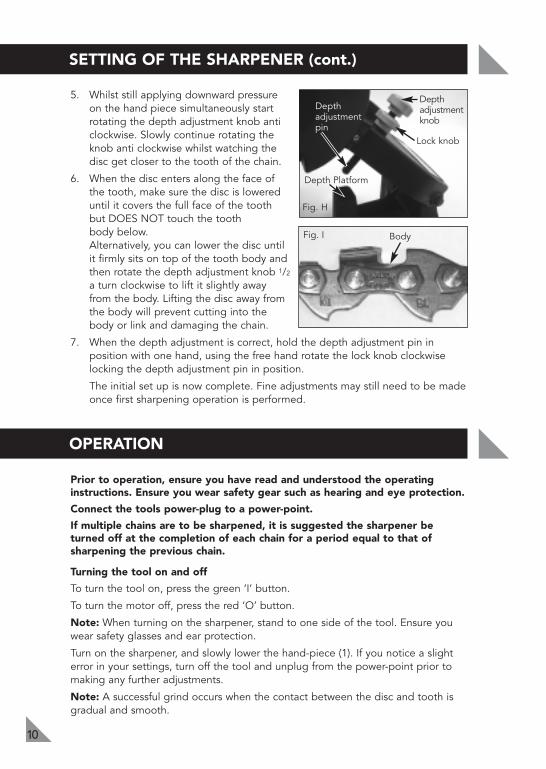
5. Whilst still applying downward pressureon the hand piece simultaneously startrotating the depth adjustment knob anticlockwise. Slowly continue rotating theknob anti clockwise whilst watching thedisc get closer to the tooth of the chain.
6. When the disc enters along the face ofthe tooth, make sure the disc is lowereduntil it covers the full face of the toothbut DOES NOT touch the tooth body below.Alternatively, you can lower the disc untilit firmly sits on top of the tooth body andthen rotate the depth adjustment knob 1/2
a turn clockwise to lift it slightly awayfrom the body. Lifting the disc away fromthe body will prevent cutting into thebody or link and damaging the chain.
7. When the depth adjustment is correct, hold the depth adjustment pin inposition with one hand, using the free hand rotate the lock knob clockwiselocking the depth adjustment pin in position.
The initial set up is now complete. Fine adjustments may still need to be madeonce first sharpening operation is performed.
Prior to operation, ensure you have read and understood the operatinginstructions. Ensure you wear safety gear such as hearing and eye protection.
Connect the tools power-plug to a power-point.
If multiple chains are to be sharpened, it is suggested the sharpener beturned off at the completion of each chain for a period equal to that ofsharpening the previous chain.
Turning the tool on and off
To turn the tool on, press the green ‘I’ button.
To turn the motor off, press the red ‘O’ button.
Note: When turning on the sharpener, stand to one side of the tool. Ensure youwear safety glasses and ear protection.
Turn on the sharpener, and slowly lower the hand-piece (1). If you notice a slighterror in your settings, turn off the tool and unplug from the power-point prior tomaking any further adjustments.
Note: A successful grind occurs when the contact between the disc and tooth isgradual and smooth.
OPERATION
Fig. I
Lock knob
Depthadjustmentknob
Depth Platform
Fig. H
Body
Depthadjustmentpin

OPERATION (cont.)
11
Caution: During operation, it is important not to overload the sharpener. Thesharpener should run at almost full speed at all times. If too much pressure is applied,the sharpener will start to slow down (noticed mainly by the dramatic audible changeof the motor.
Should the sharpener speed slow down, allow the hand-piece (1) to raise up a little(in effect allowing the disc to lift away from the chain) and let the motor return to fullspeed before continuing to sharpen.
The chain saw chain is fitted with two sets of teeth, usually every second tooth is theopposite to the last. When there is an odd number of teeth in the chain, the teethcan be doubled up ie. left, left, right.
Should the chain have an odd number of teeth, check to find this point, and beaware of this condition.
The sharpening process consists of two operations. These are, setting to the left, andthen setting the right. It is suggested to sharpen all of the teeth that face one side(every second tooth) and then proceeding to sharpen all the teeth on the opposite side.
It is important to always ensure the tooth is correctly located against the chain stop,the chain is correctly locked in place, the initial set-up as previously described hasbeen correctly carried out, and the correct safety gear is being worn.
With the chain correctly aligned against the chain stop and the depth stop set (referto Setting instructions prior to the operation), start the tool whilst standing to oneside of the grinding disc and allow the motor to run for several seconds (allowing themotor to get up to full speed).
Check the above settings by carefully lowering the grinding disc down the face of thetooth until the hand-piece (1) comes to a stop.
As the grinding disc passes down the face of the tooth, it should be a light even pass.
DO NOT attempt to try and make a heavy pass. It should be a very light “brush” ofthe front face of the tooth. If the cut is too heavy, stop and allow the hand-piece (1)to rise back up, and turn the tool off. If the pass was too heavy, adjust the chain stopadjusting knob (15) in an anti-clockwise direction slightly (suggest no more than 1/8of a turn). Then tighten the chain stop adjusting knob lock nut (14).
Once sharpening of the tooth completed, rotate the guide clamp lever (13) fully to the leftto un-lock the chain clamp (sliding guide).
Slide the chain to the right, allowing the chain stop to ride over the links and teethuntil the next tooth (orientated the same as the first tooth) rides under the stop.
When the tooth slides under the chain stop, gently slide the chain to the left so thestop engages and locates the tooth.
With the rear of the tooth firmly located, lock the clamping lever, and repeat thecutting test. If the grinding disc is not grinding sufficient off the face of the tooth,repeat the above adjustment but rotate the chain stop adjustment knob (15) clockwise.
Lower the hand-piece (in effect lowering the disc) fully until the disc reaches thebottom of the tooth. Check to ensure the grinding disc has not cut into the chain link.If the grinding disc touches the chain link, re-set the stop by adjusting the depth ofgrind knob (3) in a clock wise direction (suggest 1/8 turn at a time). Re-test after each adjustment.

OPERATION (cont.)
12
Note: Movement of the chain through the chain clamp (sliding guide) should befrom the HANGING chain as shown. Movement of the chain should NOT be fromthe top of the clamp area.
To move the chain, the clamp lever (13) should be loosened then gently pulldownwards on the hanging chain. After the tooth to be sharpened has passedunder the stop, gently pull the chain via the hanging chain to the left until the stoplocates the chain tooth.
Always select the correct orientated tooth for the set up for the table.
Sharpening teeth in opposite direction
1. Ensure the sharpener is turned off and the disc is not rotating.
2. Check the angle of the table of the current setting, loosen the angle lockingknob (10), and rotate the table to the opposite side, but to the samecorresponding angle.
3. Lock the angle locking knob firmly.
4. Using the same method above, release the clamping lever and move the chain tothe right and locate the first chain tooth with the opposite orientation from thefirst sharpening process. The settings should be the same, however when makingthe first cut always take care and check the amount being cut off the tooth, andalso the depth of the cut. Check both of these settings and adjust accordingly.
Removing a disc
1. Disconnect the sharpener from the power supply.
2. Remove the 3 screws holding the disc cover to the sharpener housing.
3. Lift off the cover.
4. Hold the disc with one hand and using the free hand turn the knob at thecentre of the disc anti clockwise. Remove the knob.
5. Remove the disc and replace with a new one.
Fitting a disc
1. Replace a new disc over the spindle.
2. Replace the locking knob and screw clockwise (hold the disc with the freehand to ensure the locking knob can be tightened properly).
3. Replace the cover.
4. Secure cover by fixing the 3 screws through the cover back into the sharpener housing.

MAINTENANCE
13
Keep the Sharpener clean and free of dust, metal debris and dirt.
Check the grinding disc before each use to make sure it isn’t damaged. Do not use agrinding disc if it is chipped, cracked, or worn. You can check if the wheel has cracksnot visible to the human eye by hanging it up by the central hole and tapping it with anon metal object (ie. screwdriver handle). If it is in good condition it will produce ametallic sound. A dull sound indicates a crack or break.
Replace the grinding disc when it grinds down to a diameter of 3 inches.
Filing the chain depth
If the chain has been repeatedly sharpened, the chain depth limiting gauges (depthgauge) may need to be filed down with a flat file (not included).
The depth of the depth gauges should be NOmore than 0.5mm below the cutters.
Always disconnect the sharpener from the powersupply prior to making any adjustments orperforming any maintenance.
Ensure replacement discs are rated at 4,800/minor higher. Using a disc rated below the speed ofthe sharpener is a hazard.
Periodically check that all nuts, bolts and other fixings are properly tightened.
Note: Ozito Industries will not be responsible for any damage or injuries caused byrepair of the tool by an unauthorised person or mishandling or mistreatment of thetool. This tool is designed for DIY use - use in commercial or industrial environmentswill void the warranty.
DESCRIPTION OF SYMBOLS
Double insulated V Voltage
Regulator compliance mark Hz Herts
no No load speed W Wattage
/min Revolutions or reciprocation per minute Warning
~ Alternating current
!!
Depth Gauge
Cutters

CARING FOR THE ENVIRONMENT
14
AUSTRALIA (Head Office)1-23 Letcon Drive, Bangholme, Victoria, Australia 3175Telephone:1800 069 486Website: www.ozito.com.auEmail: [email protected]
1 x Chainsaw Chain Sharpener OZCCS85WA
1 x Disc (assembled)
1 x Table & lock knob
1 x Operation Manual
Power tools that are no longer usable should not bedisposed of with household waste but in an environmentallyfriendly way. Please recycle where facilities exist. Check withyour local council authority for recycling advice.
Recycling packaging reduces the need for landfill and rawmaterials. Reuse of recycled material decreases pollution in theenvironment. Please recycle packaging where facilities exist.Check with your local council authority for recycling advice.
CONTENTS
OZITO INDUSTRIES PTY LTD

WARRANTYTHIS WARRANTY FORM AND CONFIRMED BUNNINGS REGISTER RECEIPT SHOULDBE RETAINED BY THE CUSTOMER AT ALL TIMES
The warranty is only made available by returning the product to your nearestBunnings Warehouse with a confirmed Bunnings register receipt.
PURCHASED FROM:________________________________________________
DATE PURCHASED: ________________________________________________
2 YEAR REPLACEMENT WARRANTYYour Ozito tool is guaranteed for a period of 24 months from the ORIGINAL date ofpurchase under the following conditions: Professional, industrial or high frequencyuse will VOID this warranty.
WARNING
The following actions will result in the warranty being void.
• If the tool has been operated on a supply voltage other than that specified onthe unit.
• If the tool shows signs of damage or defects caused by or resulting from abuseaccidents or alterations.
• If the tool has been disassembled or tampered with in any way.
Note: Warranty excludes consumable parts such as brushes, batteries, sandingpads, blades, discs, drill bits, collets and router bits.
YOUR WARRANTY FORM SHOULD BE RETAINEDBY YOU AT ALL TIMES.
SHOULD YOU HAVE ANY QUESTIONS PRIOR TORETURNING YOUR PRODUCT FOR WARRANTY OR
REPAIR PLEASE TELEPHONE OUR CUSTOMERSERVICE HELPLINE:
Australia 1800 069 486New Zealand 0508 069 486
TO ENSURE A SPEEDY RESPONSE PLEASE HAVE THE MODEL NUMBERAND DATE OF PURCHASE AVAILABLE. AN OZITO CUSTOMER SERVICE
REPRESENTATIVE WILL TAKE YOUR CALL AND ANSWER ANY QUESTIONSYOU MAY HAVE RELATING TO THE WARRANTY POLICY OR PROCEDURE.