chair and stand user’s guidedoclibrary.com/msc167/prm/advantage 15070-101-rev-c-ug0933.pdf ·...
TRANSCRIPT

ADVANTAGEChair and Stand
User’s Guide

2 15070-101-REV-C
© 2011 Reichert, Inc. Reichert is a registered trademark of Reichert, Inc. All other trademarks are property of their respective owners.
The information contained in this document was accurate at time of publication. Specifications are subject to change without notice. Reichert, Inc. reserves the right to make changes in the product described in this manual without notice and without incorporating those changes in any products already sold.
Federal law restricts this device to sale by or on the order of a physician.
ISO 9001/13485 Certified – Reichert products are designed and manufactured under quality processes meeting ISO 9001/13485 requirements.
No part of this publication may be reproduced, stored in a retrieval system, or transmitted in any form or by any means, electronic, mechanical, recording, or otherwise, without the prior written permission of Reichert, Inc.

315070-101-REV-C
Table of Contents
Table of Contents ..........................................................................3 Warnings and Cautions ................................................................4
Symbol Information .................................................................4 Introduction ...................................................................................5
Unpacking ...............................................................................5 Features and Functions ................................................................6
Contents .................................................................................6 Installation & Assembly .................................................................8
Lower Instrument Arm .............................................................8Vertical Post Assembly ...........................................................9Optional Third Arm Installation ..............................................10Refractor Arm Assembly .......................................................10Overhead Lamp Assembly ....................................................10Counterbalance Weights ...................................................... 11Chair Set-Up ......................................................................... 11
Operation ....................................................................................12Control Panel ........................................................................12 Main ON/OFF Switch .......................................................12 Chair UP/DOWN Switch ..................................................12 Lower Instrument Arm Outlet Switch ...............................12 Chart Projector Outlet Switch ..........................................12 Accessory Outlet Switch ..................................................12 Overhead Lamp ON/OFF Intensity Controls ....................12 Charging Wells ................................................................13 Corded Instrument Voltage Selector ................................13Lower Instrument Arm ...........................................................13Refractor Arm ........................................................................14 Counterbalance Adjustment .............................................14Overhead Lamp ....................................................................15Chair Operation ....................................................................15
Maintenance ...............................................................................16External Cleaning .................................................................16Fuses ....................................................................................16
Accessories ................................................................................16 Troubleshooting ..........................................................................17 Classification ..............................................................................18Specifications .............................................................................18Storage & Transportation ............................................................18Disposal ......................................................................................18Warranty .....................................................................................19

4 15070-101-REV-C
Warnings and Cautions
WARNING: AN INSTRUCTION THAT DRAWS ATTENTION TO RISK OF INJURY OR DEATH.
WARNING: DO NOT REMOVE OR DEFEAT THE EARTH GROUND CONNECTION ON THE ADVANTAGE CHAIR & STAND POWER INPUT CONNECTOR OR THE UNIT’S POWER CORD. DAMAGE TO THE ADVAN-TAGE CHAIR & STAND AND/OR INJURY TO THE OPERATOR MAY OCCUR. WARNING: THE ADVANTAGE CHAIR & STAND SHOULD BE USED IN STRICT ACCORDANCE WITH THE INSTRUCTIONS OUTLINED IN THIS USERS GUIDE. THE SAFETY OF THE OPERATOR AND THE PERFOR-MANCE OF THE INSTRUMENT CANNOT BE GUARANTEED IF USED IN A MANNER NOT SPECIFIED BY REICHERT OPHTHALMIC INSTRUMENTS.
WARNING: DISCONNECT POWER TO THE UNIT BEFORE OPENING ANY OF THE COVERS ON THE CHAIR OR STAND.
CAUTION: AN INSTRUCTION THAT DRAWS ATTENTION TO THE RISK OF DAMAGE TO THE PRODUCT.
CAUTION: IN ORDER TO ENSURE THAT CORRECT OPERATION OF THE ADVANTAGE CHAIR & STAND IS MAINTAINED, ANY REPAIR OR SERVICE MUST BE PERFORMED BY EXPERIENCED PERSONNEL THAT ARE TRAINED BY REICHERT OPHTHALMIC INSTRUMENTS.
CAUTION: THE INTERNAL CIRCUITRY OF THE ADVANTAGE CHAIR & STAND CONTAINS ELECTROSTATIC DISCHARGE SENSITIVE DEVICES (ESDS). SUCH COMPONENTS MAY BE SENSITIVE TO HIGH VOLTAGES PRODUCED BY STATIC CHARGES FROM THE HUMAN BODY. DO NOT REMOVE ANY OF THE COVERS OF THE ADVANTAGE CHAIR & STAND WITHOUT TAKING PROPER PRECAUTIONS OR DAMAGE TO THE ADVANTAGE CHAIR & STAND MAY OCCUR.
CAUTION: DO NOT USE SOLVENTS OR STRONG CLEANING SOLUTIONS ON ANY PART OF THE ADVAN-TAGE CHAIR & STAND OR DAMAGE TO THE UNIT MAY OCCUR.
Symbol Information
The following symbols appear on the instrument:
CAUTION: Indicates that important operating and maintenance instructions are included in this User’s Guide.
Authorization to mark give by Intertek ETL Semko for confor-mance with electrical standards.
WARNING: The lightning bolt with the arrow-head symbol within an equilateral triangle is intended to alert the user to the presence of “dangerous voltage” within the unit’s enclosure that may be of sufficient magnitude to consti-tute risk of electrical shock.
Functional Earth
On / Off
Protective Earth Type B-Class1 Product Symbol
Date of Manufacture
515070-101-REV-C
Congratulations on the purchase of your new Advantage Chair and Stand.
This User’s Guide is designed as a training and reference manual for operation, maintenance, and trouble-shooting. We recommend that you read it carefully prior to use and follow the instructions in the guide to ensure optimum performance of your new product.
Please retain this manual for future reference and to share with other users. Additional copies can be obtained from your authorized Reichert dealer or from the Reichert Customer Service department. Contact information is provided at the end of this guide.
Unpacking
Remove the plastic banding straps from the shipping carton.
Note: Open the top of the shipping carton and look inside to make sure everything is secured before re-moving the carton.
Remove the six nails from the base of the carton(s) and lift the carton(s) from the skid. Remove the acces-sories from the stand and set aside for later assembly. Remove the box containing the Head Rest and Foot Switch from the seat of the chair and set aside. Remove the two wooden braces that secure the base to the skid. You will need a claw hammer or crow/pry bar.
WARNING: TO REDUCE THE RISK OF PERSONAl INJURY OR DAMAGE TO THE STAND OR CHAIR, YOU SHOUlD HAVE SOMEONE ASSIST YOU WITH REMOVING THE STAND OR CHAIR FROM THE SKID. NEVER TRY MOVING THE STAND bY HOlDING ON TO THE CONTROl PANEl.
Carefully slide the stand or chair from the shipping skid. You will need to tilt the stand or chair to remove the skid. Maneuver the stand and chair to your desired location (be sure your location is level) and remove the remaining packing materials. Unpack the remaining component boxes.
Introduction

6 15070-101-REV-C
Features and Functions
Contents
The items listed below should be included in the Advantage Chair and Stand packaging containers. If any of these items are missing, please contact Reichert Customer Service.
Advantage Chair (P/N 15070)•Foot Switch (P/N 5070-005)•Stand Base With Control Panel and Charging Wells (P/N 15071)•Lower Instrument Arm (P/N 15073)•Overhead Lamp Assembly (P/N 15072-001)•Lamp Cord (P/N 15072-025)•Refractor Arm (P/N 15072-024)•Vertical Mounting Post (P/N 15072-029)•Extra Weights (P/N 15072-026)•User’s Guide (P/N 15070-101)•Allen Wrenches (8, 6, 5, 4, 3, 2.5, 2 mm)•Spare Fuses (Refer to • Maintenance section for fuse details.)
Overhead Lamp Assembly
Vertical Mounting Post
Refractor Arm
Stand Base with Control Panel and Charging Wells
Lower Instrument Arm
Chair
Foot Switch

715070-101-REV-C
Features and Functions (continued)
Outlets For Accessories
Chart Projector
Outlet
Corded Instrument
Binding Posts
Main Power Fuses
External Ground Terminal
Input Power Cable
Chair Connector
Rear Covers
Power Input Panel
Voltage Limit SwitchFor Corded Instruments
Hand Instrument Charging Wells
Accessory ON/OFF Switch & LED
Chair UP/DOWN Switches
Corded Instrument ON/OFF Switch
Voltage Selector Switches & Scale:Controls voltage to corded instrument binding posts on rear panel.
Overhead Lamp Brightness Control Switches and Scale
Overhead Lamp ON/OFF Switch
Charge Indicators
Lower Arm Power (Slit Lamp) ON/OFF
Switch & LED
Chart Projector ON/OFF Switch & LED
Main Power ON/OFF Switch
8 15070-101-REV-C
Installation And Assembly
WARNING: TO REDUCE THE RISK OF ElECTRICAl SHOCK, DO NOT CONNECT THIS UNIT TO A POWER SOURCE UNTIl THE ASSEMblY PROCESS IS COMPlETED.
before you begin the assembly process:
Be sure the floor is level.1. Be sure your stand is correctly positioned in the desired location.2.
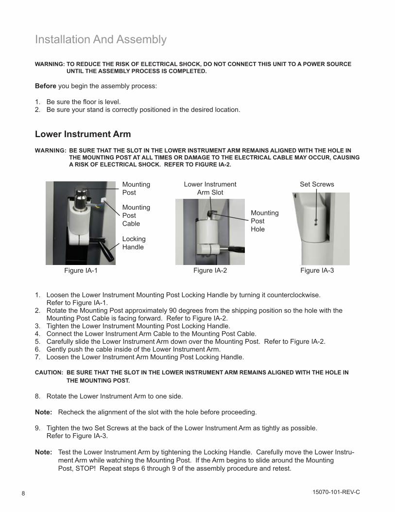
lower Instrument ArmWARNING: bE SURE THAT THE SlOT IN THE lOWER INSTRUMENT ARM REMAINS AlIGNED WITH THE HOlE IN
THE MOUNTING POST AT All TIMES OR DAMAGE TO THE ElECTRICAl CAblE MAY OCCUR, CAUSING A RISK OF ElECTRICAl SHOCK. REFER TO FIGURE IA-2.
Mounting Post
Locking Handle
Mounting Post Cable
Set ScrewsLower Instrument Arm Slot
Mounting Post Hole
Figure IA-2 Figure IA-3Figure IA-1
Loosen the Lower Instrument Mounting Post Locking Handle by turning it counterclockwise. 1. Refer to Figure IA-1.Rotate the Mounting Post approximately 90 degrees from the shipping position so the hole with the 2. Mounting Post Cable is facing forward. Refer to Figure IA-2.Tighten the Lower Instrument Mounting Post Locking Handle. 3. Connect the Lower Instrument Arm Cable to the Mounting Post Cable. 4. Carefully slide the Lower Instrument Arm down over the Mounting Post. Refer to Figure IA-2.5. Gently push the cable inside of the Lower Instrument Arm. 6. Loosen the Lower Instrument Arm Mounting Post Locking Handle. 7.
CAUTION: bE SURE THAT THE SlOT IN THE lOWER INSTRUMENT ARM REMAINS AlIGNED WITH THE HOlE IN THE MOUNTING POST.
Rotate the Lower Instrument Arm to one side. 8.
Note: Recheck the alignment of the slot with the hole before proceeding.
Tighten9. the two Set Screws at the back of the Lower Instrument Arm as tightly as possible. Refer to Figure IA-3.
Note: Test the Lower Instrument Arm by tightening the Locking Handle. Carefully move the Lower Instru-ment Arm while watching the Mounting Post. If the Arm begins to slide around the Mounting Post, STOP! Repeat steps 6 through 9 of the assembly procedure and retest.
915070-101-REV-C
Installation And Assembly (continued)
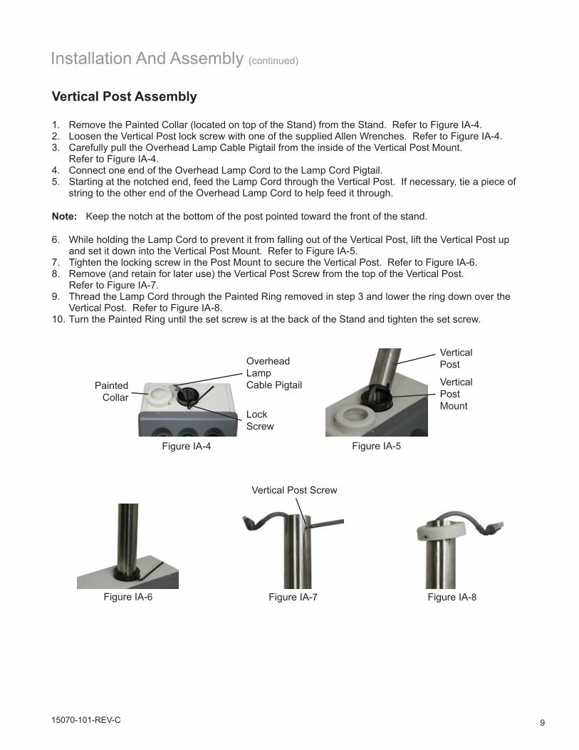
Vertical Post Assembly
Remove the Painted Collar (located on top of the Stand) from the Stand. Refer to Figure IA-4.1. Loosen the Vertical Post lock screw with one of the supplied Allen Wrenches. Refer to Figure IA-4.2. Carefully pull the Overhead Lamp Cable Pigtail from the inside of the Vertical Post Mount. 3. Refer to Figure IA-4.Connect one end of the Overhead Lamp Cord to the Lamp Cord Pigtail.4. Starting at the notched end, feed the Lamp Cord through the Vertical Post. If necessary, tie a piece of 5. string to the other end of the Overhead Lamp Cord to help feed it through.
Note: Keep the notch at the bottom of the post pointed toward the front of the stand.
While holding the Lamp Cord to prevent it from falling out of the Vertical Post, lift the Vertical Post up 6. and set it down into the Vertical Post Mount. Refer to Figure IA-5.Tighten the locking screw in the Post Mount to secure the Vertical Post. Refer to Figure IA-6.7. Remove (and retain for later use) the Vertical Post Screw from the top of the Vertical Post. 8. Refer to Figure IA-7.Thread the Lamp Cord through the Painted Ring removed in step 3 and lower the ring down over the 9. Vertical Post. Refer to Figure IA-8.Turn the Painted Ring until the set screw is at the back of the Stand and tighten the set screw.10.
Vertical Post
Vertical Post Mount
Figure IA-5
Painted Collar
Lock Screw
Overhead Lamp Cable Pigtail
Figure IA-4
Vertical Post Screw
Figure IA-6 Figure IA-7 Figure IA-8

10 15070-101-REV-C
Installation And Assembly (continued)
Optional Third Arm Installation
With the Locking Ring facing down, feed the Lamp Cord through the mounting hole of the Third Arm.1. Slide the Third Arm, with the Lock Ring toward the bottom, down over the Vertical Post to the desired 2. location and tighten the Locking Ring Allen Screw.Remove the two shipping nuts. Do not remove the washers.3. Install the two Locking Handles supplied with the Third Arm.4. Remove the Access Cover over the Auxiliary Power Panel and plug the Third Arm Power Cord into the 5. outlet labeled ACC.
Refractor Arm Assembly
With the Locking Ring facing down, feed the Lamp Cord through the Mounting Hole of the Refractor Arm.1. Slide the Refractor Arm (with the Lock Ring to the bottom) down over the Vertical Post to the desired 2. position and tighten the Locking Ring Allen Screw. Refer to Figure IA-9.Screw the Locking Handle into the Refractor Arm and tighten. Refer to Figure IA-10.3. Slide the Refractor Mounting Bar in the Refractor Arm and tighten. Refer to Figure IA-11.4.
Locking Ring Allen Screw
Lock Ring
Refractor Mounting Bar
Figure IA-9 Figure IA-10 Figure IA-11
Locking Handle
Overhead lamp Assembly
Connect the Overhead Lamp Cord to the Overhead Lamp. Refer to Figure IA-12.1. Raise the Overhead Lamp and insert the Lamp Bushing into the Vertical Post. Refer to Figure IA-13.2. Reinstall the Vertical Post Screw removed from the top of the Vertical Post. Refer to Figure IA-13.3.
Overhead Lamp Cord
Lamp Busing Vertical
Post Screw
Figure IA-12 Figure IA-13
1115070-101-REV-C
Installation And Assembly (continued)
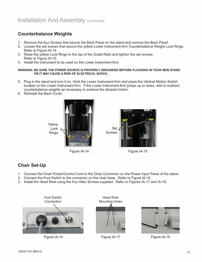
Counterbalance Weights
Remove the four Screws that secure the Back Panel on the stand and remove the Back Panel.1. Loosen the set screws that secure the yellow Lower Instrument Arm Counterbalance Weight Lock Rings. 2. Refer to Figure IA-14.Raise the yellow Lock Rings to the top of the Guide Rails and tighten the set screws. 3. Refer to Figure IA-15.Install the instrument to be used on the Lower Instrument Arm. 4.
WARNING: bE SURE THE POWER SOURCE IS PROPERlY GROUNDED bEFORE PlUGGING IN YOUR NEW STAND OR IT MAY CAUSE A RISK OF ElECTRICAl SHOCK.
Plug in the stand and turn it on. Hold the Lower Instrument Arm and press the Vertical Motion Switch 5. located on the Lower Instrument Arm. If the Lower Instrument Arm jumps up or down, add or subtract counterbalance weights as necessary to achieve the desired motion.Reinstall the Back Cover.6.
Yellow Lock
Rings
Figure IA-14 Figure IA-15
Chair Set-Up
Connect the Chair Power/Control Cord to the Chair Connector on the Power Input Panel of the stand.1. Connect the Foot Switch to the connector on the chair base. Refer to Figure IA-16.2. Install the Head Rest using the four Allen Screws supplied. Refer to Figures IA-17 and IA-18.3.
Foot Switch Connection
Head Rest Mounting Holes
Figure IA-16 Figure IA-17 Figure IA-18
Set Screws

12 15070-101-REV-C
Operation
Control Panel
The Control Panel (See page 7 for Control Panel diagram) contains all of the electrical controls except (1) the Main Power ON/OFF Switch, (2) a secondary Chair UP/DOWN Switch and (3) the Lower Arm Vertical Motion Switch.
Main ON/OFF SwitchThe Main ON/OFF Switch controls the electric power for the entire stand. This switch is a rocker type with an internal lamp that glows green when the power is ON. Press the side with the straight line “I” to turn the stand ON. You will hear a beep that indicates the stand is energized. Press the side with the circle “O” to turn the stand OFF.
Chair UP/DOWN Switch Press and hold the UP Arrow to raise the chair. Press and hold the DOWN Arrow to lower the chair. Single press the DOWN Arrow for Auto-Down.
Note: Chair can be operated from Foot-Switch or Lower Arm Switch as well.
lower Instrument Arm Outlet SwitchThe S.L. Switch is a push type on-off switch to control the electricity to the outlet on the Lower Instru-ment Arm. If the switch is off, depressing it once will turn it on and apply power to the outlet on the Lower Instrument Arm. If the switch is on, depressing it once will turn the switch off. An LED just to the left of the switch illuminates to indicate the switch is on.
Chart Projector Outlet SwitchThe C.P. Switch is a push type on-off button. It controls the electricity to the C.P. Outlet on the lower left of the Auxiliary Power Panel. If the switch is OFF, pressing the switch once will turn it on. If the switch is on, pressing the switch once will turn it off. An LED just to the left of the switch lights up when the switch is ON.
Accessory Outlet SwitchThe ACC Switch is a push type on-off switch. It controls the electricity to the ACC Outlets on the left and upper right of the Power Input Panel. If the switch is OFF, pressing the switch once will turn it ON. If the switch is ON, pressing the switch once will turn it OFF. An LED just to the left of the switch lights up when the switch is ON.
Overhead lamp ON/OFF Intensity ControlsCAUTION: DO NOT USE A bUlb RATED HIGHER THAN 60 WATTS OR EXCESSIVE HEATING MAY OCCUR.
The area labeled “LAMP” has 3 separate buttons and a minimum to maximum LED scale. Pressing the Left or Right Arrow one position at a time will increase or decrease lamp intensity. Pressing the POWER Switch will apply power to the Overhead Lamp. The LED on the scale will flash indicating power is applied to the lamp. You will hear a “beep” if the voltage has been changed from a previous setting. Pressing the POWER Switch again removes power from the Overhead Lamp and the LED will remain ON.
Note: There is also a rocker type switch on the Lower Arm of the Overhead Lamp. This switch must be ON for the Touch Pad Controls to work.
1315070-101-REV-C
Operation (continued)
Charging WellsThe Charging Wells are designed for hand-held instruments with a rechargeable battery. The Charging Wells will charge instrument batteries as long as the instrument handle is fully inserted in the well. There is a Charge Indicator Light beneath each well that indicates an instrument is properly seated and charg-ing.
Note: Your hand-held instruments must be turned OFF prior to placing them in the Charging Well. Ad-ditionally, the Stand Main ON/OFF Switch must be ON for the instrument batteries to charge.
CAUTION: DO NOT ATTEMPT TO STORE HANDlES THAT USE ONlY AlKAlINE bATTERIES IN THE CHARGING WEllS OR DAMAGE TO THE CHARGING WEllS OR HAND-HElD INSTRUMENTS MAY OCCUR.
Corded Instrument Voltage SelectorLocate the Voltage Limit Switch for corded instruments (P. 7) located on the rear of the stand. Using a small flathead screwdriver, adjust the switch to the maximum voltage of your corded instrument con-nected to the Binding Post.
CAUTION: DO NOT SElECT A VOlTAGE THAT EXCEEDS THE VOlTAGE RATING OF THE bUlb IN YOUR IN-STRUMENT OR DAMAGE TO THE bUlb MAY OCCUR.
Once the maximum voltage has been selected, press the Power Button in the area labeled “VOLTAGE” to turn your corded instrument on and off. Pressing the Left or Right Arrow one position at a time will increase or decrease the voltage to the corded instrument connected to the Binding Posts of the stand within the range of the maximum voltage set by the Voltage Limit Switch on the rear of the stand.
lower Instrument Arm WARNING: THE lOWER INSTRUMENT ARM CAN RISE AbRUPTlY IF THE VERTICAl MOTION SWITCH IS DE-
PRESSED WHEN THE ARM IS IN THE DOWN POSITION AND IS NOT bAlANCED. DO NOT lEAVE THE ARM IN THE DOWN POSITION WITHOUT AN INSTRUMENT INSTAllED ON THE ARM OR ACCIDENTAl MOVEMENT OF THE ARM MAY OCCUR, CAUSING ACCIDENTAl INJURY.
The Lower Instrument Arm is counter-balanced by means of weights contained within the stand. Depending on which instrument you install, it may be necessary to add or remove weights to fine tune the balance of the Lower Instrument Arm.
To move the Lower Instrument Arm up or down, grasp the arm firmly then press and hold the Vertical Motion Switch while raising or lowering the arm. Release the switch to lock the Lower Instrument Arm in the desired position.
The Lower Instrument Arm can be rotated 180 degrees to the left or right about the lower pivot point by releasing the Locking Handle located on the lower portion of the Lower Instrument Arm.
The intermediate section of the Lower Instrument Arm can be rotated about its pivot point by releasing the Locking Handle located in the middle of the Lower Instrument Arm.
Note: To release the Locking Handle, turn it counterclockwise. To tighten the Locking Handle, turn it clock-wise.
The outer-most portion of the Lower Instrument Arm is a stiff friction joint capable of being rotated 180 degrees and will stay in position. The knob at the end of the arm locks the rotation of the instrument about its pivot point.
14 15070-101-REV-C
Operation (continued)
Refractor ArmWARNING: THE REFRACTOR ARM CAN RISE AbRUPTlY IF THE lOCKING HANDlE IS RElEASED, WHEN THE
ARM HAS bEEN lEFT IN A DOWNWARD POSITION, AND IT HAS NOT bEEN bAlANCED. DO NOT lOCK THE ARM IN THE lOWER POSITION WITHOUT A REFRACTOR INSTAllED OR ACCIDENTAl MOVE-MENT OF THE ARM MAY OCCUR, CAUSING ACCIDENTAl INJURY.
The Refractor Arm can be operated by releasing the Locking Handle. Push the handle away from yourself to release it. Pull the handle toward yourself to lock the Refractor Arm in place. The Locking Handle controls all vertical and rotational movement of the arm.
Counterbalance Adjustment
To “fine tune” the counterbalancing action of the Refractor Arm:
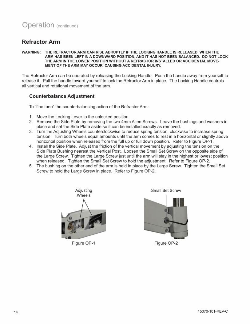
Move the Locking Lever to the unlocked position.1. Remove the Side Plate by removing the two 4mm Allen Screws. Leave the bushings and washers in 2. place and set the Side Plate aside so it can be installed exactly as removed.Turn the Adjusting Wheels counterclockwise to reduce spring tension, clockwise to increase spring 3. tension. Turn both wheels equal amounts until the arm comes to rest in a horizontal or slightly above horizontal position when released from the full up or full down position. Refer to Figure OP-1.Install the Side Plate. Adjust the friction of the vertical movement by adjusting the tension on the 4. Side Plate Bushing nearest the Vertical Post. Loosen the Small Set Screw on the opposite side of the Large Screw. Tighten the Large Screw just until the arm will stay in the highest or lowest position when released. Tighten the Small Set Screw to hold the adjustment. Refer to Figure OP-2.The bushing on the other end of the arm is held in place by the Large Screw. Tighten the Small Set 5. Screw to hold the Large Screw in place. Refer to Figure OP-2.
Adjusting Wheels
Small Set Screw
Figure OP-1 Figure OP-2
1515070-101-REV-C
Operation (continued)
Overhead lampWARNING: THE OVERHEAD lAMP SHADE CAN GET VERY HOT. DO NOT GRASP THE lAMPSHADE NEAR THE
bUlb TO ADJUST THE POSITION OF THE lAMP ASSEMblY OR SERIOUS INJURY MAY OCCUR.
To operate the Overhead Lamp you must:
Switch on the Main ON/OFF Switch on the front of the stand.1. Switch on the rocker switch on the lower arm of the Overhead Lamp Arm.2. Press the Lamp POWER Switch on the Control Panel.3. Press the Left or Right Arrow to increase or decrease lamp intensity. 4.
Note: The Overhead Lamp can be adjusted by holding the Lamp Assembly by the back of the housing.
Chair Operation
Note: To raise or lower the chair, the Main Power ON/OFF Switch on the front of the stand must be ON.
To raise the chair press the blue up arrow on the Foot Switch, the up arrow in the CHAIR section of the Control Panel, or the UP Switch on the Lower Instrument Arm. Single press the green down arrow on the Foot Switch, the down arrow in the CHAIR section of the Control Panel, or the DOWN Switch on the Lower Instrument Arm for the chair’s Auto-Down feature. To lower the chair incrementally, press and hold the green down arrow on the Foot Switch, the down arrow in the CHAIR section of the Control Panel, or the DOWN switch on the Lower Instrument Arm, release when chair has reached desired height.
Head RestThe Head Rest can be positioned by pulling the Lock Handle to the unlocked position, positioning the Head Rest in the desired position and squeezing the handle until it snaps into the locked position.
Chair back RestThe Back Rest can be positioned as required by squeezing the Back Rest Lock Handle and positioning the Back Rest as desired. When released, the handle will lock the Back Rest in position.
Arm RestsThe Arm Rests can be positioned in the vertical or horizontal position as desired.
Foot RestThe Foot Rest can be positioned in the upright or horizontal position as needed.
16 15070-101-REV-C
There is no periodic or routine maintenance required.
External CleaningWARNING: bEFORE ClEANING WITH A DAMP ClOTH, DISCONNECT OR UNPlUG THE STAND FROM ANY POWER
SOURCE.
CAUTION: DO NOT USE SOlVENTS OR STRONG ClEANING SOlUTIONS ON ANY PART OF THE ADVANTAGE CHAIR & STAND OR DAMAGE TO THE UNIT MAY OCCUR.
Clean the external surfaces of this instrument using a clean, soft cloth moistened with a mild detergent solu-tion (1 cc of liquid dish soap to one liter of clean, filtered water (filtered below 5 microns)).
Fuses WARNING: bEFORE CHECKING THE FUSES, DISCONNECT OR UNPlUG THE STAND FROM ANY POWER SOURCE.
Binding Post Fuse 2AL-250VLamp Fuse 4AH-250VMain Stand Fuse 10AL-250VChain Fuse 10AL-250V
Accessories P/N Description15070-005 Foot Switch 15072-026 Extra Weights15070-101 User’s Guide15073 Keratometer Arm12092 Projector Arm15070-016 Advantage Chair Extension Cord15070-001 Power Cord (used on the Chair w/out the Stand)
Maintenance
1715070-101-REV-C
Troubleshooting
If your Stand does not function at all:
Check your facility power source. Is the outlet “live”? 1. Check your electrical connections.2. Check the Fuses located on the Power Input Panel.3.
WARNING: TO HElP PREVENT THE POSSIbIlITY OF ElECTRICAl SHOCK, AlWAYS UNPlUG THE STAND bEFORE REMOVING OR REPlACING THE FUSES.
If the Overhead Lamp does not light:
Check the Stand Main ON/OFF Switch.1. Check the ON/OFF Switch on the lower arm of the Overhead Lamp.2. Replace the bulb with a long life or heavy duty 60 W bulb.3.
WARNING: THE bUlb MAY bE HOT! AllOW TO COOl bEFORE REMOVING. DO NOT USE A bUlb RATED HIGHER THAN 60 WATTS.
If the Lower Instrument Arm will not move up or down:
Be sure that the Main ON/OFF Switch is ON.1. Check the position of the Counterbalance Weight Lock Rings.2.
18 15070-101-REV-C
Protection against electric shockClass [I]Type B applied parts: Surface of the ChairProtection against harmful ingress of water: OrdinaryDegree of safety in the presence of a flammable anesthetics mixture with air or with oxygen or with nitrous oxide: Not suitable for use in the presence of a flammable anesthetics mixture with air or with oxygen or with nitrous oxide.Mode of operation: Continuous
SpecificationsHeight: 75 in. (191 cm) Width: 21 in. (53.3 cm)Depth: 21 in. (53.3 cm)Weight: 370 lbs (168 kg) Electrical Rating: 120 VAC, 50-60 Hz, 10 Amps
Note: For fuse ratings, refer to the Maintenance section
Arm RangeRefractor Arm: 8 in. (20.3cm) vertical movement Lower Instrument Arm: 26.5 to 35.5 in. (67.3 cm to 90.2cm) Corded Instrument Voltages: 2.5V, 3.5V, 4.5V, 5.5V, 6.5V, 7.5V, 12V (Volts AC)
Storage & Transportation You should observe the following conditions when storing or transporting this unit:
Recommended ranges:Storage:Temperature range: -10° C to +55° CRelative humidity: 10% to 85%Atmospheric Pressure: 70 to 106 kPa
Transportation:Temperature range: -40° C to +70° CRelative humidity: 10% to 85%Atmospheric Pressure: 50 to 106 kPa
DisposalThis product does not generate any environmentally hazardous residues. At the end of its product life, follow your local laws and ordinances regarding the proper disposal of this equipment.
Classification

1915070-101-REV-C
Warranty
This product is warranted by Reichert, Inc. against defective material and workmanship under normal use for a period of one year from the date of invoice to the original purchaser. (An authorized dealer shall not be considered an original purchaser.) Under this warranty, Reichert’s sole obligation is to repair or replace the defective part or product at Reichert’s discretion.
This warranty applies to new products and does not apply to a product that has been tampered with, altered in any way, misused, damaged by accident or negligence, or which has had the serial number removed, altered or effaced. Nor shall this warranty be extended to a product installed or operated in a manner not in accordance with the applicable Reichert instruction manual, nor to a product which has been sold, ser-viced, installed or repaired other than by a Reichert factory, Technical Service Center, or authorized Reichert Dealer.
Lamps, bulbs, charts, cards and other expendable items are not covered by this warranty.
All claims under this warranty must be in writing and directed to the Reichert factory, Technical Service Center, or authorized instrument dealer making the original sale and must be accompanied by a copy of the purchaser’s invoice.
This warranty is in lieu of all other warranties implied or expressed. All implied warranties of merchantabil-ity or fitness for a particular use are hereby disclaimed. No representative or other person is authorized to make any other obligations for Reichert. Reichert shall not be liable for any special, incidental, or conse-quent damages for any negligence, breach of warranty, strict liability or any other damages resulting from or relating to design, manufacture, sale, use or handling of the product.
If notified promptly in writing of any action brought against the purchaser based on a claim that the instru-ment infringes a U.S. Patent, Reichert will defend such action at its expense and will pay costs and dam-ages awarded in any such action, provided that Reichert shall have sole control of the defense of any such action with information and assistance (at Reichert’s expense) for such defense, and of all negotiation for the settlement and compromise thereof.
Reichert reserves the right to make changes in design or to make additions to or improvements in its prod-ucts without obligation to add such to products previously manufactured. We use extreme care in selection, checking, rechecking and packing to eliminate the possibility of error. If any shipping errors are discovered:
Carefully go through the packing materials to be sure nothing was inadvertently overlooked when the 1. unit was unpacked. Call the dealer you purchased the product from and report the shortage. The materials are packed at 2. the factory and none should be missing if the box has never been opened. Claims must be filed within 30 days of purchase. 3.
Our shipping responsibility ceases with the safe delivery in good condition to the transportation company. Claims for loss or damage in transit should be made promptly and directly to the transportation company.
If, upon delivery, the outside of the packing case shows evidence of rough handling or damage, the trans-portation company’s agent should be requested to make a “Received in Bad Order” notation on the delivery receipt. If within 48 hours of delivery, concealed damage is noted upon unpacking the shipment and no exterior evidence of rough handling is apparent, the transportation company should be requested to make out a “Bad Order” report. This procedure is necessary in order for the dealer to maintain the right of recov-ery from the carrier.

20
Reichert, Inc.3362 Walden AveDepew, NY 14043
USA
Toll Free: 888-849-8955Phone: 716-686-4500
Fax: 716-686-4545Email: [email protected]
www.reichert.com
Reichert GmbHHubertstrasse 2D-82229 Seefeld
Germany
Tel: +49 8152 993530Fax: +49 8152 993535
ISO-9001/13485 Registered
15070-101 Rev. CMarch, 2011