challenger jorc (2012) mineral resources estimate
TRANSCRIPT
BARTON GOLD PTY LTD | ACN 633 445 253
5 November 2020
Private Market Announcement
CHALLENGER JORC (2012) MINERAL RESOURCES ESTIMATE
HIGHLIGHTS
➢ Challenger remnant mineralisation converted to JORC (2012) MRE of 530kt @ 3.9 g/t Au (65.6koz Au)
Preliminary Challenger JORC (2012) Mineral Resource Estimate
Barton Gold Pty Ltd (Barton or the Company) is pleased to announce that unmined and remnant mineralisation
in the Challenger underground mine has been converted to a JORC (2012) compliant Inferred Mineral Resources
Estimate (MRE) of 530kt @ 3.9 g/t Au for 65.6koz Au. The MRE has been reported at a 2 g/t Au cut-off combined
with parameters that meet the requirement for Reasonable Prospects of Eventual Economic Extraction (RPEEE).
Challenger Geology
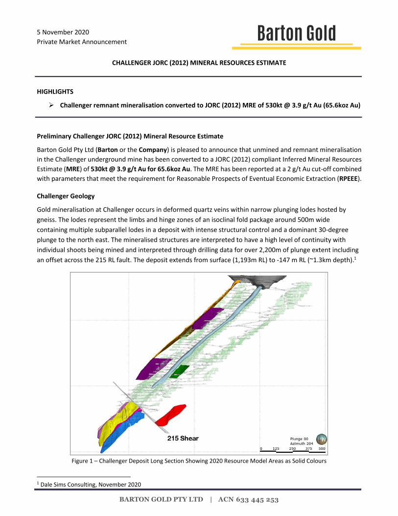
Gold mineralisation at Challenger occurs in deformed quartz veins within narrow plunging lodes hosted by
gneiss. The lodes represent the limbs and hinge zones of an isoclinal fold package around 500m wide
containing multiple subparallel lodes in a deposit with intense structural control and a dominant 30-degree
plunge to the north east. The mineralised structures are interpreted to have a high level of continuity with
individual shoots being mined and interpreted through drilling data for over 2,200m of plunge extent including
an offset across the 215 RL fault. The deposit extends from surface (1,193m RL) to -147 m RL (~1.3km depth).1
Figure 1 – Challenger Deposit Long Section Showing 2020 Resource Model Areas as Solid Colours
1 Dale Sims Consulting, November 2020

BARTON GOLD PTY LTD | ACN 633 445 253
Challenger lodes include Challenger West (CW), Challenger South-Southwest (CSSW), Aminus, M1, M2, M3 and
South East Zone (SEZ). They are offset some 150m in plan by the 215 Shear but continue to plunge at a similar
orientation below the shear and all are open to depth. M1 and M2 have been mined on several levels below the
215 Shear. The deposit has been developed to ~1,120m depth (065 mRL).2
Figure 2 – Challenger Ore Shoots in Plan View below 215 Shear
There are currently no plans for exploration or development of the Challenger underground mineralisation, with
the Company focused on extension and growth of its larger-scale exploration projects at Tarcoola and Tunkillia,
some ~130k and ~200km SE of the Challenger underground mine (respectively).
“The Challenger mine has a history as a significant gold producer in South Australia,
producing some ~1.2Moz gold from 2002 – 2018. The deposit remains open at depth and
provides optionality for future extension of mineralisation to depth, as well as a potential
source of remnant mineralisation for supplemental mill feed to the Company’s local mill.”
- Alexander Scanlon, Managing Director
For and on behalf of the Board
Alexander Scanlon Managing Director
For further information, please contact:
Alexander Scanlon Neil Rose Shannon Coates
Managing Director Director Company Secretary
[email protected] [email protected] [email protected]
+61 425 226 649 +61 419 614 783 +61 8 9322 1587
2 SRK Consulting, October 2018

BARTON GOLD PTY LTD | ACN 633 445 253
ABOUT BARTON GOLD:
Barton Gold Pty Ltd is a privately held Australian gold acquisition and development company with a primary focus on low-
capital-cost developments and optimisations of existing mines and processing infrastructure. Current major projects
include the Company’s South Australian Tarcoola Project which hosts the historical high-grade Perseverance open pit gold
mine and the neighbouring Tunkillia Gold Project which is South Australia’s largest undeveloped gold-only Resource.
The Company’s leadership and team include experienced natural resources investment and development professionals,
and the Company’s technical and execution capability are strengthened through its technical alliances with Australia’s
leading mine geology, mine engineering, processing and contract operations teams.
www.bartongold.com.au
__________________________________________________________________________________________
IMPORTANT NOTICES:
Disclaimer
This document has been prepared by Barton Gold Pty Ltd and/or its affiliates (together, “Barton”) for the exclusive use of the party to
whom Barton delivers this document (the “Recipient”). The information contained in this document has been prepared in good faith by
Barton. However, no representation or warranty, either express or implied, is made as to the accuracy, completeness, adequacy or
reliability of the information contained in this document. This document contains only a synopsis of more detailed information in relation
to the matters described herein and accordingly no reliance may be placed for any purpose whatsoever on the sufficiency or completeness
of such information as presented herein. This document should not be regarded by the Recipient as a substitute for the exercise of its
own judgment and the Recipient should conduct its own due diligence in respect of the contents of this document. To the maximum
extent permitted by law Barton, its directors, officers, employees, advisers, and agents disclaim any or all liability for any loss or damage
which may be suffered by any person as a result of the use of, or reliance upon, anything contained within or omitted from this document.
This document has been prepared solely for informational purposes. This document does not constitute a prospectus and is not to be
construed as a solicitation or an offer to buy or sell any securities, or related financial instruments, in any jurisdiction. The Recipient should
not construe the contents of this document as legal, tax, accounting or investment advice or a recommendation. The Recipient should
consult its own legal counsel, tax and financial advisors concerning any matter described herein. This document does not purport to be
all-inclusive or to contain all of the information that the Recipient may require. No investment, divestment or other financial decisions or
actions should be based solely on the information in this document. The distribution of this document may be restricted by law in certain
jurisdictions. The Recipient and any other persons who come into possession of the document must inform themselves about, and
observe, any such restrictions.
Cautionary Statement Regarding Values & Forward-Looking Information
The figures, valuations, forecasts, estimates, opinions and projections contained herein involve elements of subjective judgment and
analysis and assumption. Barton does not accept any liability in relation to any such matters, or to inform the Recipient of any matter
arising or coming to the company’s notice after the date of this document which may affect any matter referred to herein. Any opinions
expressed in this material are subject to change without notice, including as a result of using different assumptions and criteria. This
document may contain forward-looking statements. Forward-looking statements are often, but not always, identified by the use of words
such as “seek”, “anticipate”, “believe”, “plan”, “expect”, and “intend” and statements than an event or result “may”, “will”, “should”,
“could”, or “might” occur or be achieved and other similar expressions. Forward-looking information is subject to business, legal and
economic risks and uncertainties and other factors that could cause actual results to differ materially from those contained in forward-
looking statements. Such factors include, among other things, risks relating to property interests, the global economic climate, commodity
prices, sovereign and legal risks, and environmental risks. Forward-looking statements are based upon estimates and opinions at the date
the statements are made. Barton undertakes no obligation to update these forward-looking statements for events or circumstances that
occur subsequent to such dates or to update or keep current any of the information contained herein. The Recipient should not place
undue reliance upon forward-looking statements. Any estimates or projections as to events that may occur in the future (including
projections of revenue, expense, net income and performance) are based upon the best judgment of Barton from information available
as of the date of this document. There is no guarantee that any of these estimates or projections will be achieved. Actual results will vary
from the projections and such variations may be material. Nothing contained herein is, or shall be relied upon as, a promise or
representation as to the past or future. Barton, its affiliates, directors, employees and/or agents expressly disclaim any and all liability
relating or resulting from the use of all or any part of this document or any of the information contained herein.
This material must not be copied, reproduced, distributed or passed to others at any time, in whole or in part, without the prior written
consent of Barton.
BARTON GOLD PTY LTD | ACN 633 445 253
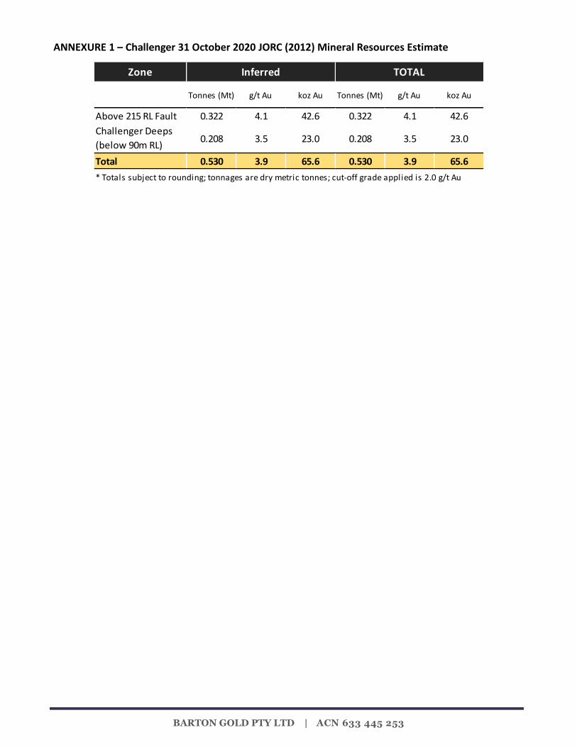
ANNEXURE 1 – Challenger 31 October 2020 JORC (2012) Mineral Resources Estimate
Zone
Tonnes (Mt) g/t Au koz Au Tonnes (Mt) g/t Au koz Au
Above 215 RL Fault 0.322 4.1 42.6 0.322 4.1 42.6
Challenger Deeps
(below 90m RL)0.208 3.5 23.0 0.208 3.5 23.0
Total 0.530 3.9 65.6 0.530 3.9 65.6
Inferred TOTAL
* Totals subject to rounding; tonnages are dry metric tonnes; cut-off grade applied is 2.0 g/t Au

BARTON GOLD PTY LTD | ACN 633 445 253
Competent Persons Statement:
The information in this announcement that relates to the Mineral Resource statement for the Challenger Goldmine is based on
information compiled by Mr Dale Sims, a Competent Person, who is a Fellow of the Australasian Institute of Mining and
Metallurgy. Mr Sims is an independent consultant engaged by Barton Gold Pty Ltd for this work and has sufficient experience
that is relevant to the style of mineralisation and type of deposit under consideration and to the activity being undertaken to
qualify as Competent Person as defined in the 2012 edition of the “ Australasian Code for Reporting of Exploration Results,
Mineral Resources ad Ore Reserves”. Mr Sims consents to the inclusion in this report of the matters based on this information in
the form and context in which it appears.

BARTON GOLD PTY LTD | ACN 633 445 253
JORC Code, 2012 Edition – Table 1
Challenger Deeps below 90 level and Remnant Areas above 215RL fault
Section 1 – Sampling Techniques and Data
Criteria JORC Code explanation Commentary
Sampling techniques
• Nature and quality of sampling (e.g. cut channels, random chips, or specific specialised industry standard measurement tools appropriate to the minerals under investigation, such as down hole gamma sondes, or handheld XRF instruments, etc.). These examples should not be taken as limiting the broad meaning of sampling.
• Include reference to measures taken to ensure sample representivity and the appropriate calibration of any measurement tools or systems used.
• Aspects of the determination of mineralisation that are Material to the Public Report.
• In cases where ‘industry standard’ work has been done this would be relatively simple (e.g. ‘reverse circulation drilling was used to obtain 1 m samples from which 3 kg was pulverised to produce a 30 g charge for fire assay’). In other cases more explanation may be required, such as where there is coarse gold that has inherent sampling problems. Unusual commodities or mineralisation types (e.g. submarine nodules) may warrant disclosure of detailed information.
• All primary samples used in the estimate are from diamond drilling. For the Challenger Deeps estimate below the 90 Level the estimate has only used diamond drilling data while for the Remnant areas above the 215 RL fault include chip sampling and sludge drilling where available.
• Core has been whole core sampled for UG BQ drilling or half core sampled for NQ surface drilling. The sample volume for the half NQ sample is approximately 13% lower than the whole core BQ sample.
• No second half core sampling or other formal sampling imprecision work on primary sampling has been undertaken. Primary samples are not weighed.
• The deposit contains particulate gold and has a high level of imprecision in the data based on duplicate crushed material subsampling results in work undertaken by the onsite laboratory.
• Based on the current nature of the drillhole assay data and its distribution/location the models produced can only be used for a global estimate and are not suitable for detailed mine planning at this stage. It is considered that for better local estimation larger primary sample volumes are required given the particulate gold present in the deposit (whole HQ core or UG RC drilling).
• Face chip and open hole percussion ‘sludge’ samples have been collected for grade control during the mine’s operation. Analysis of their subsampling and analytical imprecision indicates they have similar imprecision to DDH data. There is no sampling QAQC data from chip sampling or sludge drilling, yet they have been included to increase the number of available samples for interpolation given sampling and assay imprecision in the data.
Drilling techniques
• Drill type (e.g. core, reverse circulation, open-hole hammer, rotary air blast, auger, Bangka, sonic, etc.) and details (e.g. core diameter, triple or standard tube, depth of diamond tails, face-sampling bit or other type, whether core is oriented and if so, by what method, etc.).
• Diamond drilling data used is dominantly whole core BQ /LTK48 with some half core NQ drilling in surface holes. Sparce surface holes are the only data below ~70RL.
• Oriented core has not been used in underground drilling. Surface drilling has been oriented with a spear technique but the data not used in this work.
• All drilling has been single shot electronic surveyed on 30m nominal intervals.
• Sludge drilling was a routine grade control process and utilised a converted underground blasthole rig drilling 76mm diameter holes. Holes were drilled through a collar stuffing box
BARTON GOLD PTY LTD | ACN 633 445 253
Criteria JORC Code explanation Commentary
established within an oversize collar hole. Samples were collected into a rotating sample bag holder below the stuffing box outlet. Sample weights were not collected. Sludge holes were dominantly steeply inclined into the backs of the drives.
Drill sample recovery
• Method of recording and assessing core and chip sample recoveries and results assessed.
• Measures taken to maximise sample recovery and ensure representative nature of the samples.
• Whether a relationship exists between sample recovery and grade and whether sample bias may have occurred due to preferential loss/gain of fine/coarse material.
• Recovery data it is collected at the logging stage with core loss logged as a specific lithology.
• The gneissic host rock and gold bearing quartz veining is very competent and core loss is not significant based on a review of the database and core photos from recent UG and past surface drilling.
• Core loss for holes collared below 215RL averages 0.2% of drilled intervals above 0.2gpt Au and so is not considered significant given the general imprecision of the data (see below).
• As loss is a logged interval it is not always assayed as no sample exists in total loss zones. Where assays do occur in core loss affected intervals the average grade in the database is 3 gpt Au.
Logging • Whether core and chip samples have been geologically and geotechnically logged to a level of detail to support appropriate Mineral Resource estimation, mining studies and metallurgical studies.
• Whether logging is qualitative or quantitative in nature. Core (or costean, channel, etc.) photography.
• The total length and percentage of the relevant intersections logged.
• Core has been geologically (qualitative) and geotechnically (quantitate) logged. The site has had recent experience mining the lodes down to the 095 level and for 2400m of down plunge extent since mining began.
• All core is photographed in the core yard with a moving camera frame on the racks. Quality is variable but generally adequate to verify or investigate contact positions for lode boundaries.
• The core logging proved to be less useful in lode boundary identification compared to the core photographs given the mineralisation is vein hosted and veins are common in the gneiss and not well discriminated in the logging. Mineralised veins have a slightly different appearance being whiter rather than the dark/grey barren background veining.
• The ground is very competent and has not been a major consideration in mine design and extraction to date.
• All core is logged and assayed through the mineralised zones.
Sub-sampling techniques and sample preparation
• If core, whether cut or sawn and whether quarter, half or all core taken.
• If non-core, whether riffled, tube sampled, rotary split, etc. and whether sampled wet or dry.
• For all sample types, the nature, quality and appropriateness of the sample preparation technique.
• Quality control procedures adopted for all sub-sampling stages to maximise
• For Challenger Deep the samples used in the estimate are from diamond drilling while for the Remnant Areas above the 215RL fault the full dataset is used (diamond drilling samples plus chip and sludge samples).
• Core has been whole core sampled for UG BQ drilling or half core sampled for NQ2 surface drilling. The sample volume for either sample is approximately equal.
• No second half core sampling or other formal sampling imprecision work on primary sampling has been undertaken.
• The deposit contains particulate gold and has a

BARTON GOLD PTY LTD | ACN 633 445 253
Criteria JORC Code explanation Commentary
representivity of samples.
• Measures taken to ensure that the sampling is representative of the in situ material collected, including for instance results for field duplicate/second-half sampling.
• Whether sample sizes are appropriate to the grain size of the material being sampled.
high level of imprecision in the assay data based on duplicate crushed material subsampling results from work undertaken by the onsite laboratory.
• It is considered that for better local estimation larger primary sample volumes are required given the particulate gold present in the deposit (whole HQ core or UG RC drilling). Imprecision studies on core samples should also be undertaken.
Quality of assay data and laboratory tests
• The nature, quality and appropriateness of the assaying and laboratory procedures used and whether the technique is considered partial or total.
• For geophysical tools, spectrometers, handheld XRF instruments, etc., the parameters used in determining the analysis including instrument make and model, reading times, calibrations factors applied and their derivation, etc.
• Nature of quality control procedures adopted (e.g. standards, blanks, duplicates, external laboratory checks) and whether acceptable levels of accuracy (i.e. lack of bias) and precision have been established.
• All sample types at Challenger are assayed on-site using the PAL1000 process which uses accelerated Cn leaching of a ~400gm crushed aliquot during pulverisation within a steel flask using grinding media plus an accelerant tablet. This technique has been applied due to the recognised high nugget of the deposit yet yields imprecise and at times biased data.
• Primary samples are crushed to -10mm top size then rotary sample divided (RSD) to produce the flask charge. The resultant slurry is subsampled to ~100ml and centrifuged with the leachate then diluted and read for Au via an AAS instrument.
• As only leachable gold is recovered in the process the method is considered ‘partial’ although no indications of refractory/nonleachable Au were reported or recognised over the mine life.
• Duplicate samples (1:25) indicate a high level of imprecision and bias in the primary assay vs duplicate. The bias is thought to be due to poor subsampling practices where operators hand grab material circumventing the effective working of the RSD.
• CRM materials also run through the process indicate sporadic accuracy issues and blanks indicate a level of material carry over between flask charges can occur in the process.
• External fire assay (FA) checks indicate an overall bias between PAL1000 data and external lab data where original PAL data is biased high compared to FA data. This is thought again to be largely due to subsampling errors in obtaining the check samples from crushed residues.
Verification of sampling and assaying
• The verification of significant intersections by either independent or alternative company personnel.
• The use of twinned holes.
• Documentation of primary data, data entry procedures, data verification, data storage (physical and electronic) protocols.
• Discuss any adjustment to assay data.
• PAL1000 assays are duplicated during the primary batch at 1:25 (termed R1 assays) but are also duplicated on request (termed R2 assays) to verify assays over 2gpt Au. R2 sample requests also include flanking intervals. Analysis of original assay / R1 and original assay / R2 paired data for the Challenger Deeps area indicates original samples are around 7% higher grade on average than R1 duplicates and 13% higher than R2 duplicates. These biases are believed to come from improper subsampling where hand grabbing of duplicate ‘splits’ from crushed residue bags reduces fines content.
• Imprecision is a material issue for the data as is relatively small aliquot in the PAL1000 compared
BARTON GOLD PTY LTD | ACN 633 445 253
Criteria JORC Code explanation Commentary
to the ‘industry standard’ of total sample preparation by pulverising mill. The verification of specific significant intersections is difficult in this high nugget environment where 50-60% of gold is recovered in the gravity circuit.
• No holes are twinned, while data processing and management uses an access database.
• Overall the verification/calibration of the data at a ‘global’ scale has been undertaken using comparison of lode-bounded OK models produced with the mill-reconciled production data for multi-level production areas. Metallurgical accounting data will also contain error yet over a large volume of production it is anticipated errors will tend to cancel out, but that may not be the case.
Location of data points
• Accuracy and quality of surveys used to locate drill holes (collar and down-hole surveys), trenches, mine workings and other locations used in Mineral Resource estimation.
• Specification of the grid system used.
• Quality and adequacy of topographic control.
• All drillhole collars have been surveyed in by site surveyors using total station equipment. Underground drilling has used the mine survey control system to establish drill hole, sludge and chip sample location.
• Surface drilling within Challenger Deeps has hole lengths of 1500-1600m. Survey errors in long holes compound creating locational uncertainty particularly critical for narrow lode deposits such as at Challenger. This locational uncertainty can impact confidence in interpretation where lode intercepts can not be confidently correlated over long distances/depths.
• It is a metric grid based on the surveyed mine coordinate system. For grid conversion data see the prior public report (2017 resource statement).
• Topographic control is not critical in this environment as the terrain is very flat and the site under survey control due to mining activity / statutory requirements.
Data spacing and distribution
• Data spacing for reporting of Exploration Results.
• Whether the data spacing and distribution is sufficient to establish the degree of geological and grade continuity appropriate for the Mineral Resource and Ore Reserve estimation procedure(s) and classifications applied.
• Whether sample compositing has been applied.
• Data spacing in the resource areas are variable and in general significantly less in the Challenger Deeps resource below 90RL than in the Remnants around production areas. Diamond drilling is on a nominal 20-25m vertical x 10-15m horizontal grid while chip sampling exists on most faces and along sidewalls on 3m intervals. Sludge drilling is on 10-20m spaced up-hole rings along drives.
• Sampling intervals has been dominantly 1m in diamond drilling and face chips while sludge drilling has been sampled on 0.8-1.0m intervals.
Orientation of data in relation to geological structure
• Whether the orientation of sampling achieves unbiased sampling of possible structures and the extent to which this is known, considering the deposit type.
• If the relationship between the drilling orientation and the orientation of key mineralised
• Diamond drilling platforms were limited underground, and so highly skewed angles can exist between the drillhole and lodes on the extremities of the pattern coverage. Highly oblique intercepts were excluded from lode geometry modelling particularly in Challenger Deeps.
• In general, drillhole intercepts in the remnant areas are at high angles to the lodes and so are well oriented for lode definition.
BARTON GOLD PTY LTD | ACN 633 445 253
Criteria JORC Code explanation Commentary
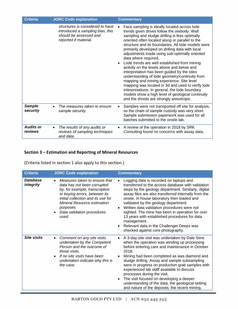
structures is considered to have introduced a sampling bias, this should be assessed and reported if material.
• Face sampling is ideally located across lode trends given drives follow the orebody. Wall sampling and sludge drilling is less optimally oriented often located along or parallel to the structure and its boundaries. All lode models were primarily developed on drilling data with local adjustments made using sub-optimally oriented data where required.
• Lode trends are well established from mining activity on the levels above and below and interpretation has been guided by the sites understanding of lode geometry/continuity from mapping and mining experience. Site level mapping was located in 3d and used to verify lode interpretations. In general, the lode boundary models show a high level of geological continuity and the shoots are strongly anisotropic.
Sample security
• The measures taken to ensure sample security.
• Samples were not transported off site for analysis, so the chain of sample custody was very short. Sample submission paperwork was used for all batches submitted to the onsite lab.
Audits or reviews
• The results of any audits or reviews of sampling techniques and data.
• A review of the operation in 2018 by SRK Consulting found no concerns with assay data.
Section 3 – Estimation and Reporting of Mineral Resources
(Criteria listed in section 1 also apply to this section.)
Criteria JORC Code explanation Commentary
Database integrity
• Measures taken to ensure that data has not been corrupted by, for example, transcription or keying errors, between its initial collection and its use for Mineral Resource estimation purposes.
• Data validation procedures used.
• Logging data is recorded on laptops and transferred to the access database with validation steps by the geology department. Similarly, digital assay files are also transferred internally from the onsite, in-house laboratory then loaded and validated by the geology department.
• Written data validation procedures were not sighted. The mine has been in operation for over 13 years with established procedures for data management.
• Relevant data in the Challenger Deeps was checked against core photography.
Site visits • Comment on any site visits undertaken by the Competent Person and the outcome of those visits.
• If no site visits have been undertaken indicate why this is the case.
• A 3-day site visit was undertaken by Dale Sims when the operation was winding up processing before entering care and maintenance in October 2018.
• Mining had been completed as was diamond and sludge drilling. Assay and sample subsampling were in progress on production grab samples with experienced lab staff available to discuss processes during the visit.
• The visit focused on developing a deeper understanding of the data, the geological setting and nature of the deposits, the recent mining,

BARTON GOLD PTY LTD | ACN 633 445 253
Criteria JORC Code explanation Commentary
production and milling performance and history of the site.
• Although the mine was closing key staff from geology, exploration and processing departments were made available for meetings during and after the site visit.
Geological interpretation
• Confidence in (or conversely, the uncertainty of) the geological interpretation of the mineral deposit.
• Nature of the data used and of any assumptions made.
• The effect, if any, of alternative interpretations on Mineral Resource estimation.
• The use of geology in guiding and controlling Mineral Resource estimation.
• The factors affecting continuity both of grade and geology.
• The lode arrangement, trends, continuity, and models are interpreted using understanding from prior experience mining the deposit on the levels above and/or below.
• Lodes were modelled on diamond drilling data primarily with adjustment from face chip and sludge data where considered prudent.
• The constraining lodes for the mineralisation have proved to be extremely continuous on a broad scale due to the highly dominant structural control on the deposit. The shoots have been mined or traced for over 2400m down plunge and across a major fault offset (215 level fault) yet the distribution of grade within lodes is considered difficult to model and predict locally based on current drilling data alone; this is attributed to the high nugget of the mineralisation and subsequent sampling and assay data imprecision.
• Lode models were based on a combination of geology and grade data. Lode boundary models were developed on a threshold mineralisation envelope of ~0.20gpt Au in combination with veining as verified in core photos and located level mapping.
• The approach was to model the structure across its full width and not sub-domained into higher grade intervals. The sampling and assay imprecision requires a ‘whole of structure’ approach as modelling discrete high-grade zones will likely overstate high grade continuity and hence Au metal.
• Once the lode envelopes were modelled grades were then estimated within the domain using the lode envelope as a hard boundary constraint with a trend based on the lodes local geometry to guide anisotropy. Sample grades across the modelled contact shows a clear sharp contact between very weakly mineralised country rock and the lodes and the 0.2gpt Au grade threshold is considered appropriate for mineralised lode definition in preference to a higher threshold.
• Barren dykes which cross-cut the lodes have been modelled and removed from the resource estimates.
Dimensions • The extent and variability of the Mineral Resource expressed as length (along strike or otherwise), plan width, and depth below surface to the upper and lower limits of the Mineral Resource.
• The areas of interest include lodes which variably extend from the top of fresh rock near surface down to the 215 fault, a major offsetting structure in the deposit, around 1600m down plunge. Below the 215 fault the Challenger Deeps lodes extend over 600m down plunge with 360m of lode interpreted to extend below to base of mining

BARTON GOLD PTY LTD | ACN 633 445 253
Criteria JORC Code explanation Commentary
activity.
Estimation and modelling techniques
• The nature and appropriateness of the estimation technique(s) applied and key assumptions, including treatment of extreme grade values, domaining, interpolation parameters and maximum distance of extrapolation from data points. If a computer assisted estimation method was chosen include a description of computer software and parameters used.
• The availability of check estimates, previous estimates and/or mine production records and whether the Mineral Resource estimate takes appropriate account of such data.
• The assumptions made regarding recovery of by-products.
• Estimation of deleterious elements or other non-grade variables of economic significance (e.g. sulphur for acid mine drainage characterisation).
• In the case of block model interpolation, the block size in relation to the average sample spacing and the search employed.
• Any assumptions behind modelling of selective mining units.
• Any assumptions about correlation between variables.
• Description of how the geological interpretation was used to control the resource estimates.
• Discussion of basis for using or not using grade cutting or capping.
• The process of validation, the checking process used, the comparison of model data to drill hole data, and use of reconciliation data if available.
• Grades estimation is by Ordinary Kriging constrained by wireframe models of the lodes.
• Input data is a combined DDH, sludge and chip sampling database for the Remnant Area estimates above the 215 fault, and diamond drilling alone below the fault. Sample length was standardised (composited) at 1m however sample diameter/volume varies within and between the data types.
• Extreme sample grades were controlled via top cutting / capping of composite values during the kriging. A range of percentile-based grade cutting thresholds were applied to produce a range of grade and metal estimates.
• The estimates chosen for reporting are based on cuts determined from mill reconciled production from volumes near the declared resources where possible. Where this is not possible similar top cut percentiles were applied as per reconciled areas.
• There are no equivalent 3D block model estimates using diamond drill hole data (with or without sludge and chip data) for the areas studied. No 3D block models have been reported for the project over its life.
• Data imprecision, spacing and lode interpretation / location at depth due to sparse data and potential survey error remain major uncertainties in the estimates.
• Modelling of domains was undertaken in Leapfrog and spatial analysis and grade estimation in Isatis with specialist assistance.
• Block size is 1m cross strike and 10m both along strike and in RL. Blocks were oriented to be in the average plane of the lode.
• No sub-blocking is employed given the global nature of the estimate.
• The proportion of barren dyke is written into each block for reporting.
• Data spacing varies by type and area ranging from 20m (down dip) x 10m ( along strike) in well drilled areas opening out to 40m x 25m or 60m x 30m nominal spacing in some of the Remnant Areas above the 215 fault. In the Challenger Deeps area limited drill platforms result in close spaced data in adjacent lodes with spacing opening significantly with distance given the ‘radiating’ drill pattern. The down dip intercepts from surface drilling are on 100m+ spacings.
• Interpolation was single pass using 150m major, 50m semimajor and 4m minor search dimensions. Models were validated against production data / volumes where possible or through visual and trend plot inspection.
• There are no modelled by-products as only gold is assayed. Around 3-5% Ag reports to the dore. No deleterious elements exist in the deposit. The mine does not produce significant acid mine
BARTON GOLD PTY LTD | ACN 633 445 253
Criteria JORC Code explanation Commentary
waste and the climate is arid.
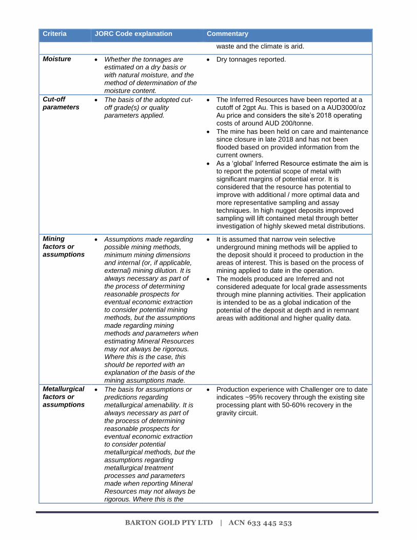
Moisture • Whether the tonnages are estimated on a dry basis or with natural moisture, and the method of determination of the moisture content.
• Dry tonnages reported.
Cut-off parameters
• The basis of the adopted cut-off grade(s) or quality parameters applied.
• The Inferred Resources have been reported at a cutoff of 2gpt Au. This is based on a AUD3000/oz Au price and considers the site’s 2018 operating costs of around AUD 200/tonne.
• The mine has been held on care and maintenance since closure in late 2018 and has not been flooded based on provided information from the current owners.
• As a ‘global’ Inferred Resource estimate the aim is to report the potential scope of metal with significant margins of potential error. It is considered that the resource has potential to improve with additional / more optimal data and more representative sampling and assay techniques. In high nugget deposits improved sampling will lift contained metal through better investigation of highly skewed metal distributions.
Mining factors or assumptions
• Assumptions made regarding possible mining methods, minimum mining dimensions and internal (or, if applicable, external) mining dilution. It is always necessary as part of the process of determining reasonable prospects for eventual economic extraction to consider potential mining methods, but the assumptions made regarding mining methods and parameters when estimating Mineral Resources may not always be rigorous. Where this is the case, this should be reported with an explanation of the basis of the mining assumptions made.
• It is assumed that narrow vein selective underground mining methods will be applied to the deposit should it proceed to production in the areas of interest. This is based on the process of mining applied to date in the operation.
• The models produced are Inferred and not considered adequate for local grade assessments through mine planning activities. Their application is intended to be as a global indication of the potential of the deposit at depth and in remnant areas with additional and higher quality data.
Metallurgical factors or assumptions
• The basis for assumptions or predictions regarding metallurgical amenability. It is always necessary as part of the process of determining reasonable prospects for eventual economic extraction to consider potential metallurgical methods, but the assumptions regarding metallurgical treatment processes and parameters made when reporting Mineral Resources may not always be rigorous. Where this is the
• Production experience with Challenger ore to date indicates ~95% recovery through the existing site processing plant with 50-60% recovery in the gravity circuit.
BARTON GOLD PTY LTD | ACN 633 445 253
Criteria JORC Code explanation Commentary
case, this should be reported with an explanation of the basis of the metallurgical assumptions made.
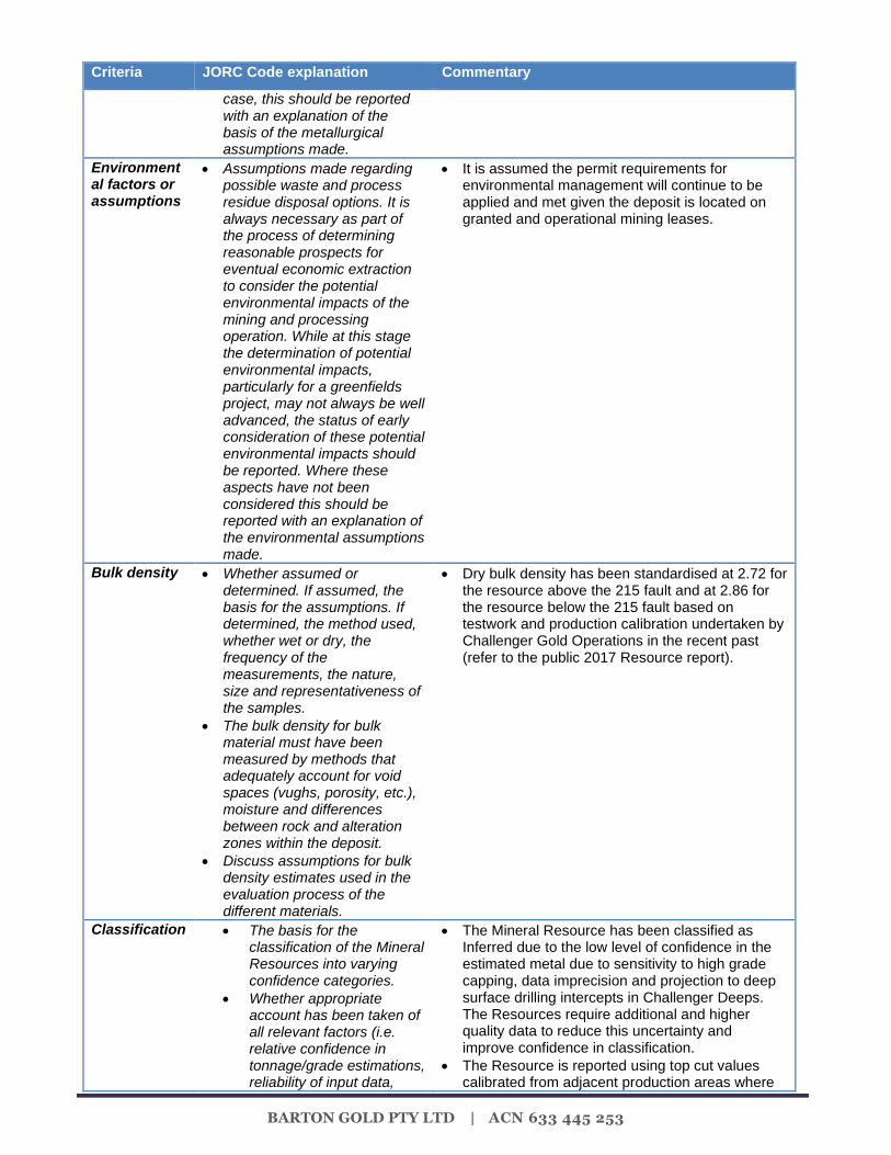
Environmental factors or assumptions
• Assumptions made regarding possible waste and process residue disposal options. It is always necessary as part of the process of determining reasonable prospects for eventual economic extraction to consider the potential environmental impacts of the mining and processing operation. While at this stage the determination of potential environmental impacts, particularly for a greenfields project, may not always be well advanced, the status of early consideration of these potential environmental impacts should be reported. Where these aspects have not been considered this should be reported with an explanation of the environmental assumptions made.
• It is assumed the permit requirements for environmental management will continue to be applied and met given the deposit is located on granted and operational mining leases.
Bulk density • Whether assumed or determined. If assumed, the basis for the assumptions. If determined, the method used, whether wet or dry, the frequency of the measurements, the nature, size and representativeness of the samples.
• The bulk density for bulk material must have been measured by methods that adequately account for void spaces (vughs, porosity, etc.), moisture and differences between rock and alteration zones within the deposit.
• Discuss assumptions for bulk density estimates used in the evaluation process of the different materials.
• Dry bulk density has been standardised at 2.72 for the resource above the 215 fault and at 2.86 for the resource below the 215 fault based on testwork and production calibration undertaken by Challenger Gold Operations in the recent past (refer to the public 2017 Resource report).
Classification • The basis for the classification of the Mineral Resources into varying confidence categories.
• Whether appropriate account has been taken of all relevant factors (i.e. relative confidence in tonnage/grade estimations, reliability of input data,
• The Mineral Resource has been classified as Inferred due to the low level of confidence in the estimated metal due to sensitivity to high grade capping, data imprecision and projection to deep surface drilling intercepts in Challenger Deeps. The Resources require additional and higher quality data to reduce this uncertainty and improve confidence in classification.
• The Resource is reported using top cut values calibrated from adjacent production areas where
BARTON GOLD PTY LTD | ACN 633 445 253
Criteria JORC Code explanation Commentary
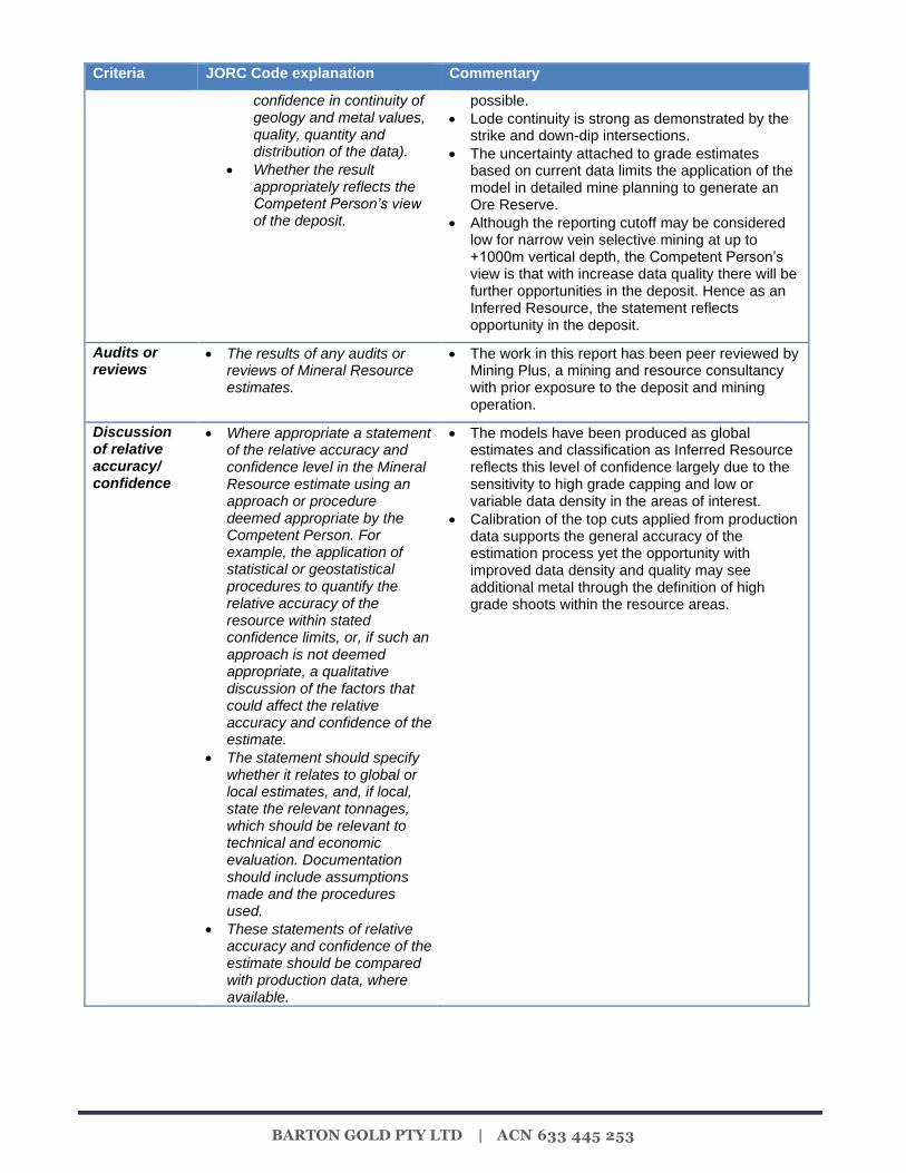
confidence in continuity of geology and metal values, quality, quantity and distribution of the data).
• Whether the result appropriately reflects the Competent Person’s view of the deposit.
possible.
• Lode continuity is strong as demonstrated by the strike and down-dip intersections.
• The uncertainty attached to grade estimates based on current data limits the application of the model in detailed mine planning to generate an Ore Reserve.
• Although the reporting cutoff may be considered low for narrow vein selective mining at up to +1000m vertical depth, the Competent Person’s view is that with increase data quality there will be further opportunities in the deposit. Hence as an Inferred Resource, the statement reflects opportunity in the deposit.
Audits or reviews
• The results of any audits or reviews of Mineral Resource estimates.
• The work in this report has been peer reviewed by Mining Plus, a mining and resource consultancy with prior exposure to the deposit and mining operation.
Discussion of relative accuracy/ confidence
• Where appropriate a statement of the relative accuracy and confidence level in the Mineral Resource estimate using an approach or procedure deemed appropriate by the Competent Person. For example, the application of statistical or geostatistical procedures to quantify the relative accuracy of the resource within stated confidence limits, or, if such an approach is not deemed appropriate, a qualitative discussion of the factors that could affect the relative accuracy and confidence of the estimate.
• The statement should specify whether it relates to global or local estimates, and, if local, state the relevant tonnages, which should be relevant to technical and economic evaluation. Documentation should include assumptions made and the procedures used.
• These statements of relative accuracy and confidence of the estimate should be compared with production data, where available.
• The models have been produced as global estimates and classification as Inferred Resource reflects this level of confidence largely due to the sensitivity to high grade capping and low or variable data density in the areas of interest.
• Calibration of the top cuts applied from production data supports the general accuracy of the estimation process yet the opportunity with improved data density and quality may see additional metal through the definition of high grade shoots within the resource areas.