challenges in flight control design development and ... techniques/ppt/v patel... · challenges in...
TRANSCRIPT

Challenges in Flight Control Design Development and TestingDevelopment and Testing
Dr. Vijay V. Patelj yNational Control Law Team
Aeronautical Development Agency, Bangalore
Flight Control Theory and PracticeS i i lik d l h d hi h h l• Scientists like to develop methods which have general applicability
• Flight control system has evolved over a century and it• Flight control system has evolved over a century and it is safety critical for modern high performance aircrafts.
• Flight control engineers are extremely conservative g g y(would like to use proven design techniques)
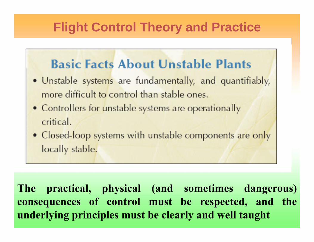
Respect the Unstable
The practical, physical (and sometimes dangerous)consequences of control must be respected, and theunderlying principles must be clearly and well taught


Overview
• The Airframe• The Control Law Design Cycle• Ground Testing and Validation• Flight Testsg• Design Challenges• The Way AheadThe Way Ahead

Salient Features of LCALight weight, single engine, multirole supersonic aircraft with all weather day / night capability
Tail‐less compound delta airframe configuration uses extensive carbon composites and co‐cured co‐bonded technology for realizing low weight and high strength
Relaxed longitudinal stability with scheduled leading edge slats for high alpha maneuvering and combat
Quadruplex all digital fly‐by‐wire flight control system with built‐in redundancy management system and re‐configurable control laws ensures safety of flight with agility and maneuverability
Oct 06, 2013 Pravartana 2013 TEQIP Workshop
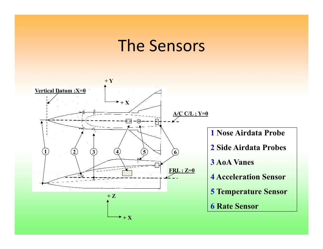
The SensorsThe Sensors
Vertical Datum :X=0
+ Y
+ X
A/C C/L ; Y=0
1 Nose Airdata Probe
FRL : Z=0
1 2 3 4 5 62 Side Airdata Probes
3 AoA VanesFRL : Z 0
+ Z
4 Acceleration Sensor
5 Temperature Sensor
+ X
6 Rate Sensor
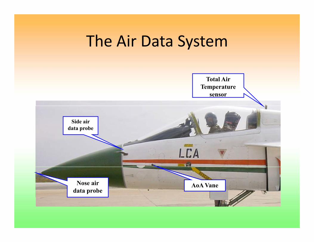
The Air Data SystemThe Air Data System
Total Air Temperature
sensor
Side air data probe
AoA VaneNose air data probe
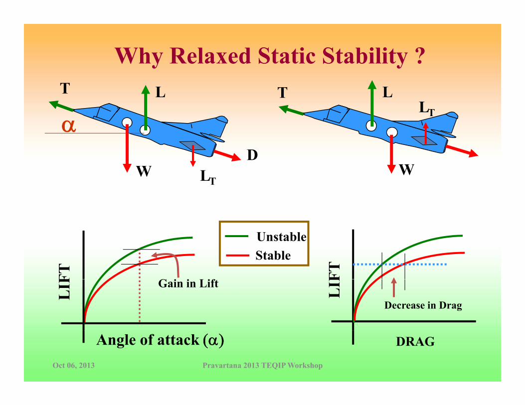
Why Relaxed Static Stability ?LTLT
LTα
WWD
L
α
LT
FTFT
UnstableStable
G i i if
LIF
LIF Gain in Lift
Decrease in Drag
DRAGAngle of attack (α)Oct 06, 2013 Pravartana 2013 TEQIP Workshop

Oct 06, 2013 Pravartana 2013 TEQIP Workshop

Limits on Level of InstabilityLimits on Level of Instability
• Hardware (actuator, sensors etc.) capabilities poses restriction on level of
Kq(Tθ2s+1)(s/σ - 1)(s/ τ + 1)
ω2ζ ω s + ω2s2 + 2-
+
- Hardware Plant
Outputinput
pinstability– if K1 > K2, aircraft can
never be stabilised
KGain
Hrd Modenever be stabilised– more stringent
requirement for t i i
X
XX O
K2CH
Hrd. Mode
guaranteeing margins i.e. for ±6 dB gain margin 1/2 K1 ≤ 2Κ2 X
XX OK11/Tθ2 σ
CHHrd. Mode
Oct 06, 2013 Pravartana 2013 TEQIP Workshop

Key Elements which affect the yperformance of FCS
Airframe
Control Laws and associated HardwareControl Laws and associated Hardware
Pilot Seat location
Stick Characteristics and Type
DisplaysDisplays
Operating Environment (Cockpit / External)
Oct 06, 2013 Pravartana 2013 TEQIP Workshop
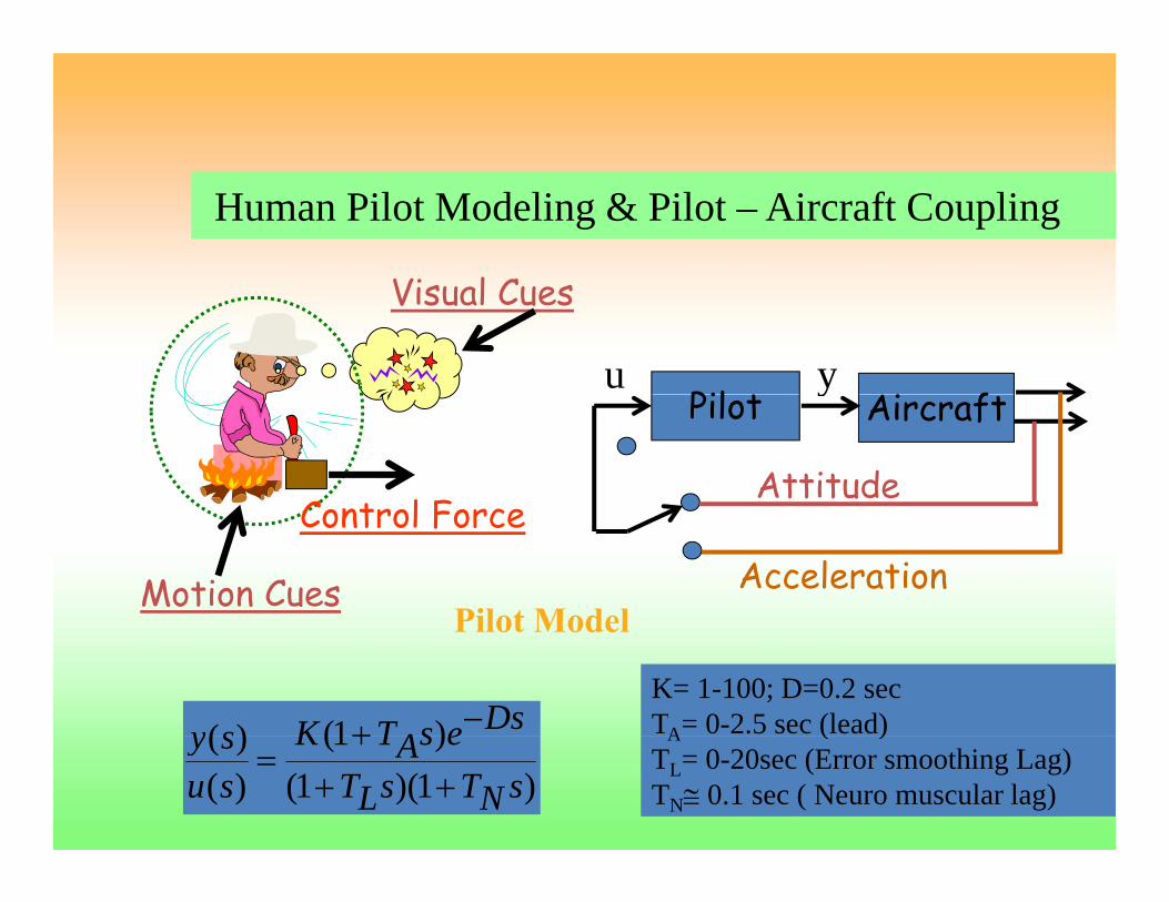
Vi l C
Human Pilot Modeling & Pilot – Aircraft Coupling
Pil t i fyu
Visual Cues
Pilot Aircraft
Attitude
y
C nt l FAcceleration
Control Force
Motion CuesPilot Model
K= 1-100; D=0.2 secTA= 0-2.5 sec (lead)
Pilot Model
)1()( DsesATKsy −+ A ( )TL= 0-20sec (Error smoothing Lag)TN≅ 0.1 sec ( Neuro muscular lag))1)(1(
)1()()(
sNTsLTesATK
susy
+++
=

Control Law RequirementsControl Law Requirements
• To Recover Stability and Provide GoodTo Recover Stability and Provide Good Handling Qualities to the Pilot– Stability Robustness y
• Guarantee the required stability margins– PIO Resistance
• Ensure good stability margins with pilot in the loop– Performance Robustness
I i t ith t t d i f l• Invariant response with respect to aerodynamics, fuel, etc.
Oct 06, 2013 Pravartana 2013 TEQIP Workshop

Margin RequirementsRequirements (Based on MIL‐SPEC‐9490D)
10 Plots of Closeness ParameterGain
Rigid4
6
8
10 Plots of Closeness Parameter
Phase
-2
0
2MarginsRequired
Gai
n (d
B)
10
-8
-6
-4
Nichols PlotStructural -180 -170 -160 -150 -140 -130 -120
-10
Phase (deg)
•For computational tractability the trapezium is approximated by an ellipse This
Oct 06, 2013 Pravartana 2013 TEQIP Workshop
•For computational tractability, the trapezium is approximated by an ellipse. This leads to the definition of a metric, Closeness Parameter (CP) that incorporates both GM and PM.

Control Law Requirements Contd…Control Law Requirements Contd…
– Level 1 Handling Qualities• Crisp and Predictable Response to the PilotC f H dli– Carefree Handling
• In respect of AoA, Sideslip, Nz, Inertia Coupling, etc.– Sufficient Structural Stability MarginsSufficient Structural Stability Margins
• No coupling with structural modes– Autopilot Modesp
• For ease of delivering stores, prevent disorientation, etc.
Oct 06, 2013 Pravartana 2013 TEQIP Workshop


Quadruplex Digital FCS - Architecture
MILMIL--STDSTD--15531553 RH LE Slat *
* - Actuators
MILMIL STDSTD 15531553 RH LE Slat
RH O/B Elevon *
RH I/B Elevon *
Rudder *
Rate Gyro(p, q, r)
DFCCDFCCAccelerometer (Ny,
Nz)LH I/B Elevon *
LH O/BElevon *
Air Brake *
AoA Sensor
LH LE Slat *
Crash DataFCS Analog / Discrete Signal
S i l Di i l I f
Air Data (Ps, Pt)
Serial Digital Interface
FCS Analog /
Disc FTI Signal
FTI
GUH Panel
HQPACKMathematical Model of
Aircraft Mil Specs
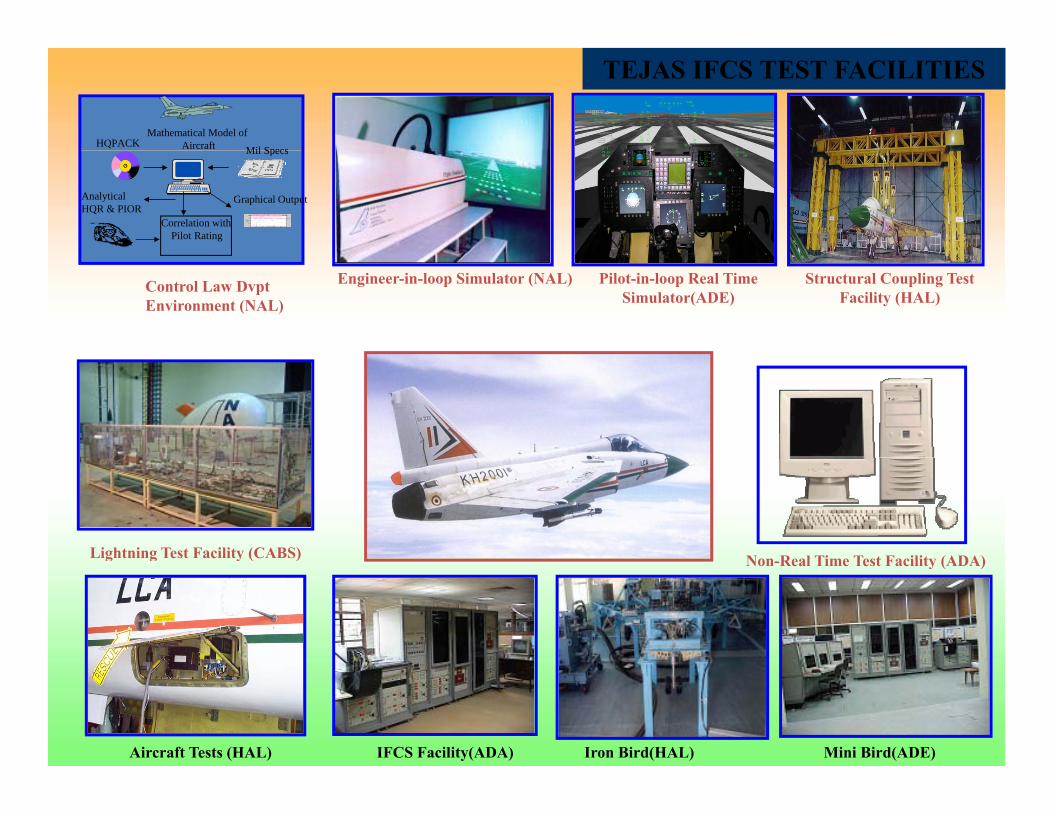
TEJAS IFCS TEST FACILITIES
Correlation withPilot Rating
Graphical Output
Mil Specs
Analytical HQR & PIOR
Control Law Dvpt Environment (NAL)
Engineer-in-loop Simulator (NAL) Pilot-in-loop Real Time Simulator(ADE)
Structural Coupling Test Facility (HAL)
Lightning Test Facility (CABS) Non Real Time Test Facility (ADA)g g y ( ) Non-Real Time Test Facility (ADA)
Aircraft Tests (HAL) IFCS Facility(ADA) Iron Bird(HAL) Mini Bird(ADE)

Multi-disciplinary modeling & Simulation Requirementsfor Fly-by-Wire Control Law Development
Aerodynamics Control
for Fly by Wire Control Law Development
AerodynamicsFlight
Dynamics
ControlEngineering
FlightC nt l S st m
Human PilotDynamics
Control System
StructuralDynamics
Landing
DynamicsPropulsion
Landing GearHydraulics
Oct 06, 2013 Pravartana 2013 TEQIP Workshop

Design Requirements
StabilityHQThe Design Cycle
REFINE
Linear Models
Linear Control
Control Law Design & HQ Analysis tools
FCS Constraints etc
N
REFINENon‐linearControl
AERO DATA BASE
D
AT
A
Control Designs
Design O K ?
NO
NO6 DOF
Control Shaping
YES
EN
GIN
E
MASS / INERTIA
Design O.K.?
O.K.?6 DOF Simulation
YES
e (k
m) Non Real
TimeReal Time (‘ELS’)
Real Time (‘RTS’)
YES
ValidatedC
Alti
tude Time ( ELS ) ( RTS )
In-flightSimulation
Control Law
Oct 06, 2013 Pravartana 2013 TEQIP Workshop
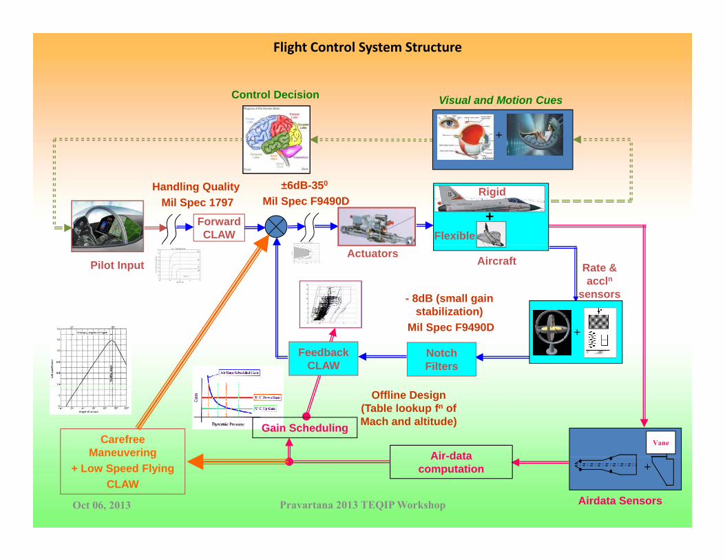
Flight Control System Structure
Visual and Motion CuesControl Decision Visual and Motion Cues
+
+Forward CLAW
±6dB-350
Mil Spec F9490DRigid
Flexible
Handling QualityMil Spec 1797
Aircraft Rate & accln
sensors
Actuators
- 8dB (small gain stabilization)
Pilot Input
+
Feedback CLAW
Notch Filters
)Mil Spec F9490D
Offline Design (Table lookup fn of Mach and altitude)
Air-data
Gain SchedulingVaneCarefree
Maneuvering
Oct 06, 2013 Pravartana 2013 TEQIP Workshop Airdata Sensors
Air-data computation +
g+ Low Speed Flying
CLAW

CLAW Reversionary ModesCLAW Reversionary Modes• AoA failure
– An equivalent AoA signal is generated for feedback by processing total normal acceleration in addition to suitably reducing the command authority.
• Airdata system failure – A fixed gain reversionary mode as an ultimate backup. – Gains are frozen at the last good value, – Pilot can then manually switch over to the standby gains using a switch in the
cockpit. – Two sets of fixed gains in the standby mode, which get automatically selected
depending on the status of the undercarriage lever.
• Elevon Failure
Oct 06, 2013 Pravartana 2013 TEQIP Workshop

Oct 06, 2013 Pravartana 2013 TEQIP Workshop

Longitudinal Feedback Controller Schematic
Gain &Low-Pass Filter
PFC10
Scheduled Gain
Nz Anti-aliasing & Notch Filters
1g cosθ
≅ ΔαNz-alpha conversion gain+
- +
+
Gain andWashout Filter
PFC10
Scheduled G i
Low-Pass FilterPST05q
Anti aliasing &
≅ Δα
Filters
+
+
+
+
Scheduled Gain and Phase Advance Filter
Gain
Scheduled Bias
Anti-aliasing & Notch Filters
≅ α.
Washout FilterPST05
+
+ ToScheduled Gain and Phase Advance Filter
Gain
+
+
++
+
+
To
de
α Signal Conditioning Filter
Bias
Low Pass Filter
Scheduled Bias
Nz-alpha conversion gain
≅ α
+α
+
+
Pt-Ps Signal Conditioning Filter &
Low Pass Filter
+
-

Longitudinal Axis Command PathLongitudinal Axis Command Path
From Feedback
Small Amplitude
Pre-Filter
Trim Correction
Small Amplitude
Pre-Filter
Trim Correction
Pitch StickShaping & Limiting
Amplitude
LargeAmplitude
Pre-Filter
Rate-LimiterDesensitizer
δeSaturation and Rate-Limiter
Pitch StickShaping & Limiting
Amplitude
LargeAmplitude
Pre-Filter
Rate-LimiterDesensitizer
δeSaturation and Rate-Limiter
Auto-Pilot
Limits as a function of Pitch Stick Command
No-Windup Integrator
Pitch Trim
Auto-Pilot
Limits as a function of Pitch Stick Command
No-Windup Integrator
Pitch Trim

Lateral/Directional Controller Schematic
No-Windup Integrator
Roll Stick
Roll Trim LimiterPitch Stick Position
Lateral
δa
p Anti-aliasing and Notch Filter
Low-Pass Filter Phase Advance
Saturation and Rate-Limiter
Roll Stick Shaping & Limiting Rate-LimiterDesensitizer Pre-Filters Gain As a function of
Pitch Stick Position
β
Signal Conditioning Filterr
≅β.
Anti-aliasing and Notch Filter
Estimate βand
β.
Estimated α
≅β
Gain and Phase Advance
GainDirectional
Ny Low Pass Filter
Filter
Anti-aliasing and Notch Filter
Pitch Stick PositionRoll Stick to Rudder Interconnect Gain
Aileron to Rudder Interconnect Gain
Rudder Pedal Shaping & Limiting
Rate-Limiter Saturation and Rate-Limiter
δr
No-Windup Integrator
Yaw Trim Limiter
Gain As a function of Pitch Stick PositionPre-Filter
g
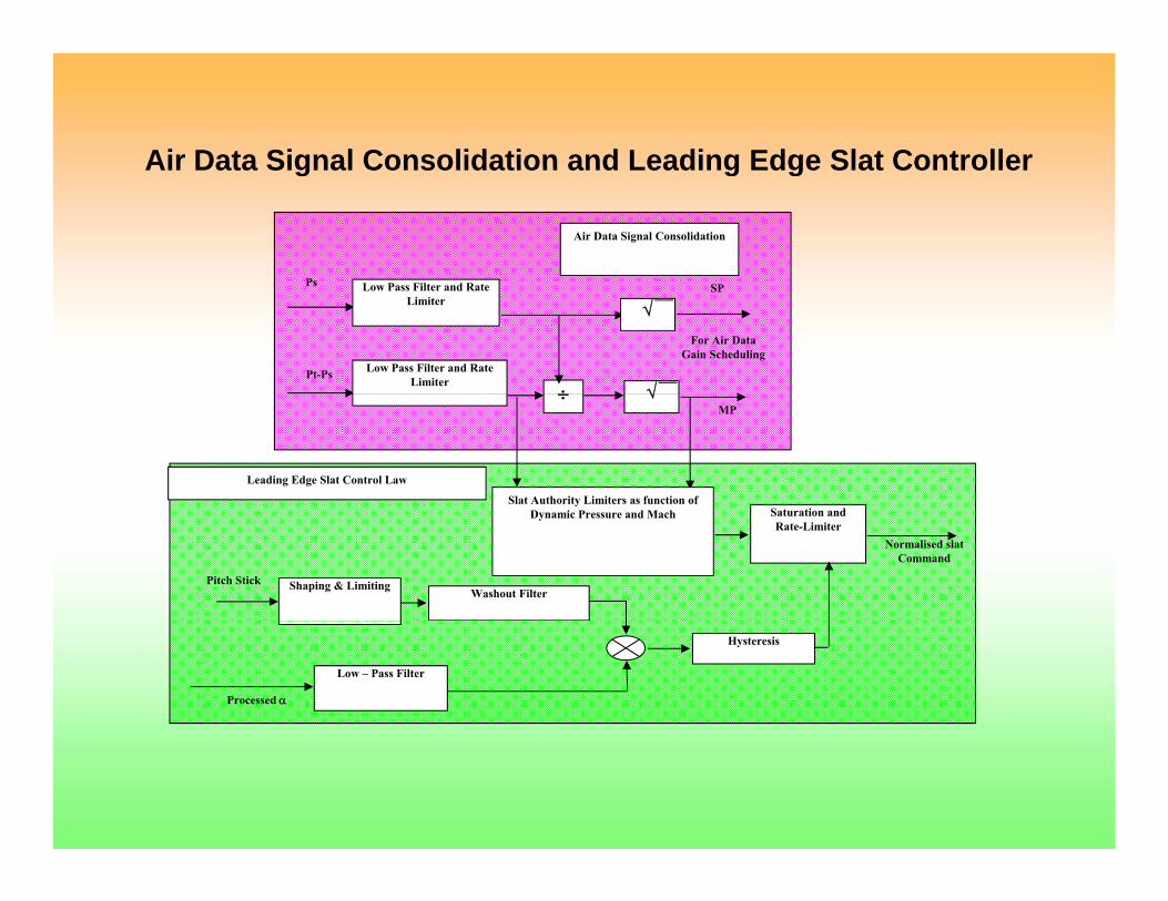
Air Data Signal Consolidation and Leading Edge Slat ControllerAir Data Signal Consolidation and Leading Edge Slat Controller
P
Air Data Signal Consolidation
Ps Low Pass Filter and Rate Limiter
Pt-Ps Low Pass Filter and Rate Limiter
÷ √
SP
For Air Data Gain Scheduling
√
÷ √MP
Slat Authority Limiters as function of
Leading Edge Slat Control Law
Normalised slat Command
Pitch Stick Shaping & Limiting
Saturation andRate-Limiter
Washout Filter
Dynamic Pressure and Mach
Hysteresis
Low – Pass Filter
Processed α

Kinematic coupling of AoA and AoSS
Oct 06, 2013 Pravartana 2013 TEQIP Workshop
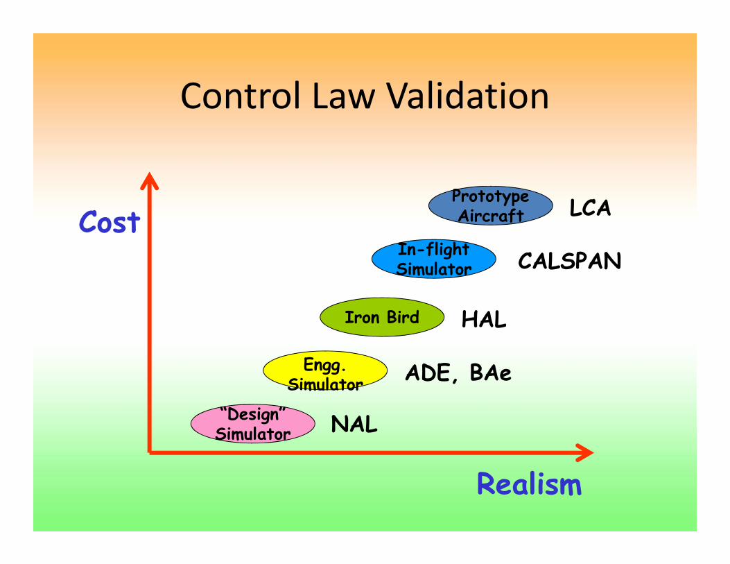
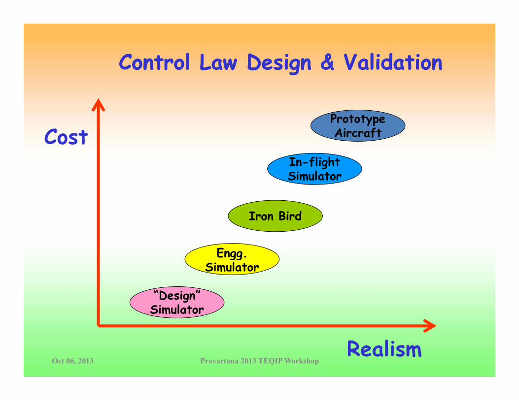
Control Law ValidationControl Law Validation
CostIn flight
PrototypeAircraft LCA
Iron Bird
In-flightSimulator
HAL
CALSPAN
Iron Bird
Engg.Simulator ADE, BAe
HAL
“Design”Simulator
Simulator
NAL
Realism

Fixed Base Real Time Flight SimulatorELS ‐ NAL

Important Requirements of RTSImportant Requirements of RTS• Accurate DynamicsAccurate Dynamics
• Realistic Delays• Realistic Delays
• Adequate Cueing for Task
• Feel System Dynamics

Importance of Pilot in theImportance of Pilot in the Loop Simulation
Visual and Motion Cues
AircraftCLAWPilot
Sensor Feedback

Man-Machine Interaction

In‐flight SimulationIn flight Simulation

Ironbird SchematicIronbird Schematic
DFCC
Test Rig Consists of Real Actuators, Undercarriage,
H d li SReal sensors
Hydraulic System
I/O RACK
Test Rig
Cockpit DH-EUADA-FDS
I/O RACKAircraft Simulation
Cockpit DH EUADA FDS Computer

Typical Test for RM LogicTypical Test for RM Logic
>Tt1/2
t /2
Ch.1t1/2Ch.2
Ch 3-t1/2
Ch.3
Ch.4-t1/2
-t /2RM Selected -t1/2Selected Value
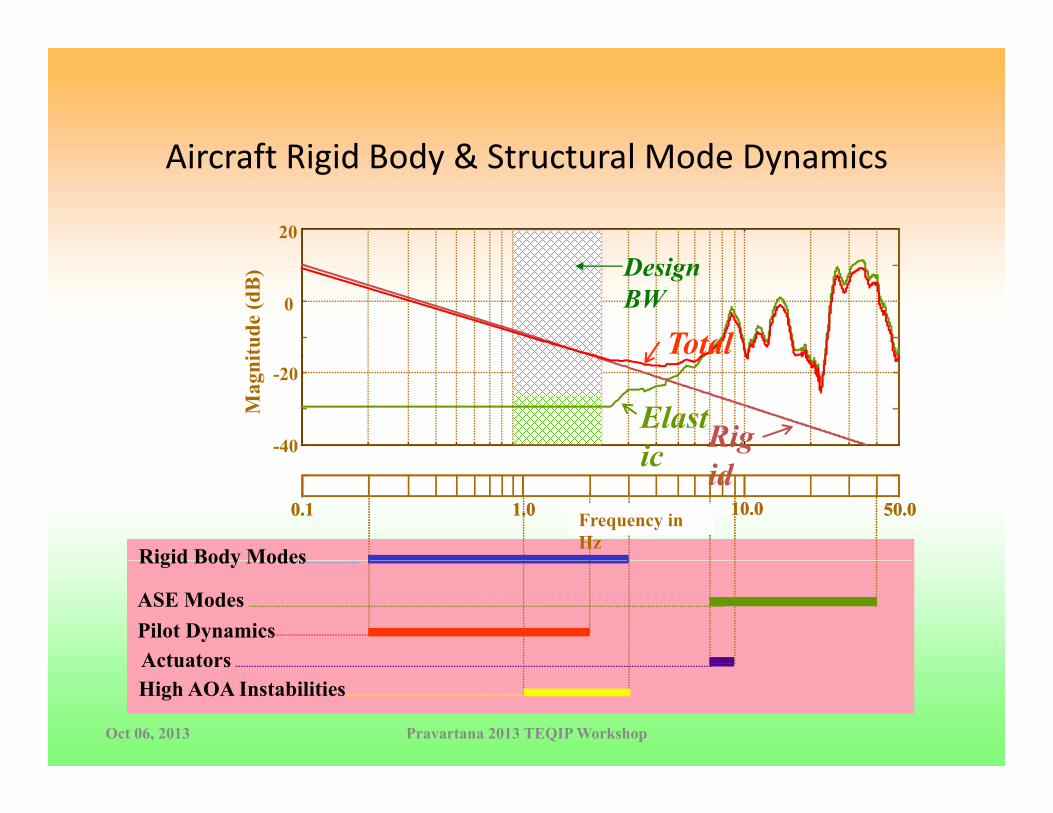
Ai ft Ri id B d & St t l M d D iAircraft Rigid Body & Structural Mode Dynamics
20
0
itude
(dB
)
Total
Design BW
-40
-20
Mag
ni
RigElastic
Rigid Body Modes
0.1 Frequency in Hz
1.0 10.0 50.0idic
Rigid Body Modes
0.1 Frequency in Hz
1.0 10.0 50.0
Rigid Body Modes
ASE ModesPilot DynamicsActuators
Rigid Body Modes
ASE ModesPilot DynamicsActuators
Oct 06, 2013 Pravartana 2013 TEQIP Workshop
ActuatorsActuatorsHigh AOA Instabilities
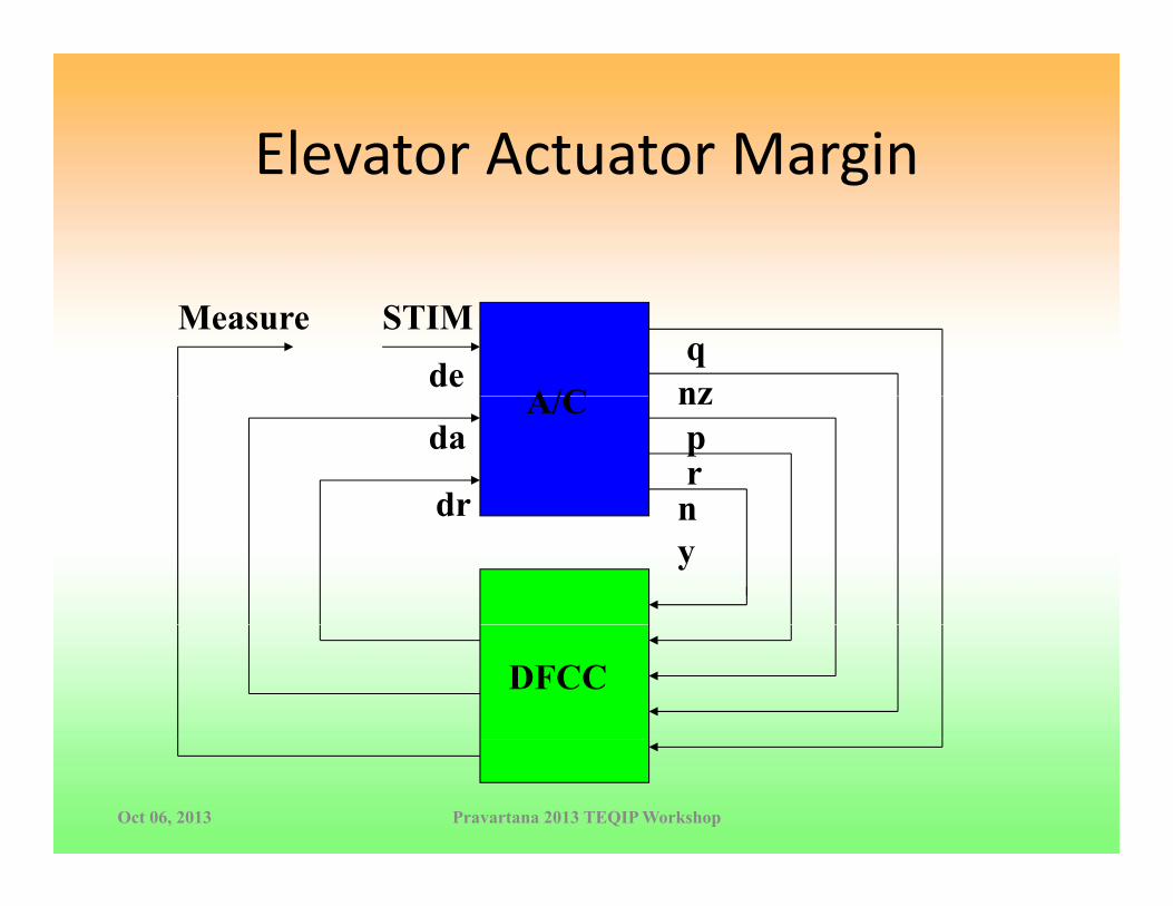
Elevator Actuator MarginElevator Actuator Margin
A/Cde
STIMMeasureqnzA/C
da
dr
nzprndr ny
DFCC
Oct 06, 2013 Pravartana 2013 TEQIP Workshop

Gain Margins –l f d hSimplified Schematic
DFCC H/Wde
A/C
q
DFCC H/WA
A/CNz
q Notch Filtersq CLAW
Nz Notch FiltersNz CLAWB
A B
Oct 06, 2013 Pravartana 2013 TEQIP Workshop
,1deAL =
deBL =2

A/de
I/PO/P qnz
Notch Filter Design based on SCT Experiments
A t ti h A/C
dadr
nzpr
ny
A systematic approach was evolved to design notch filters for the various sensor
Rigid Body Control Law
Notch Filters
paths in the presence of coupling between structural responses of all three axes of
q CLAW q NF
DFCCresponses of all three axes of the aircraft.
A difficult optimisation
P11
P12 P21qde
pproblem was converted into five independent simple optimisation problems P12 P21
P22 pda
optimisation problems without introducing conservativeness.
p CLAW p NF“A Systematic Procedure to design notch filters for structural Responses with multi-axis coupling”, AIAA Journal of Guidance, Control and Dynamics, Vol. 22, No.2, pp. 349-357, March-April 1999.Oct 06, 2013 Pravartana 2013 TEQIP Workshop
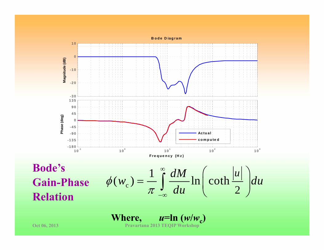
1 0B o d e D ia g r a m
-1 0
0
gnitu
de (d
B)
- 3 0
-2 0Mag
9 0
1 3 5
-1 3 5
-9 0
-4 5
0
4 5
Phas
e (d
eg)
Ac tu a l
c o m p u te d
F r e q u e n c y (H z )1 0 -1 1 0 0 1 0 1 1 0 2 1 0 3
-1 8 0
1 3 5 c o p u te d
Bode’s 1 udM∞ ⎛ ⎞Gain-PhaseRelation
c 21( ) ln coth
udMw dudu
φπ −∞
⎛ ⎞= ⎜ ⎟
⎝ ⎠∫
Where, u=ln (w/wc) Oct 06, 2013 Pravartana 2013 TEQIP Workshop
Control Law Design & ValidationControl Law Design & Validationgg
Prototype
CostIn-flightSimulator
ypAircraft
Iron Bird
Simulator
Engg.Simulator
“Design”Simulator
Oct 06, 2013 Pravartana 2013 TEQIP WorkshopRealism
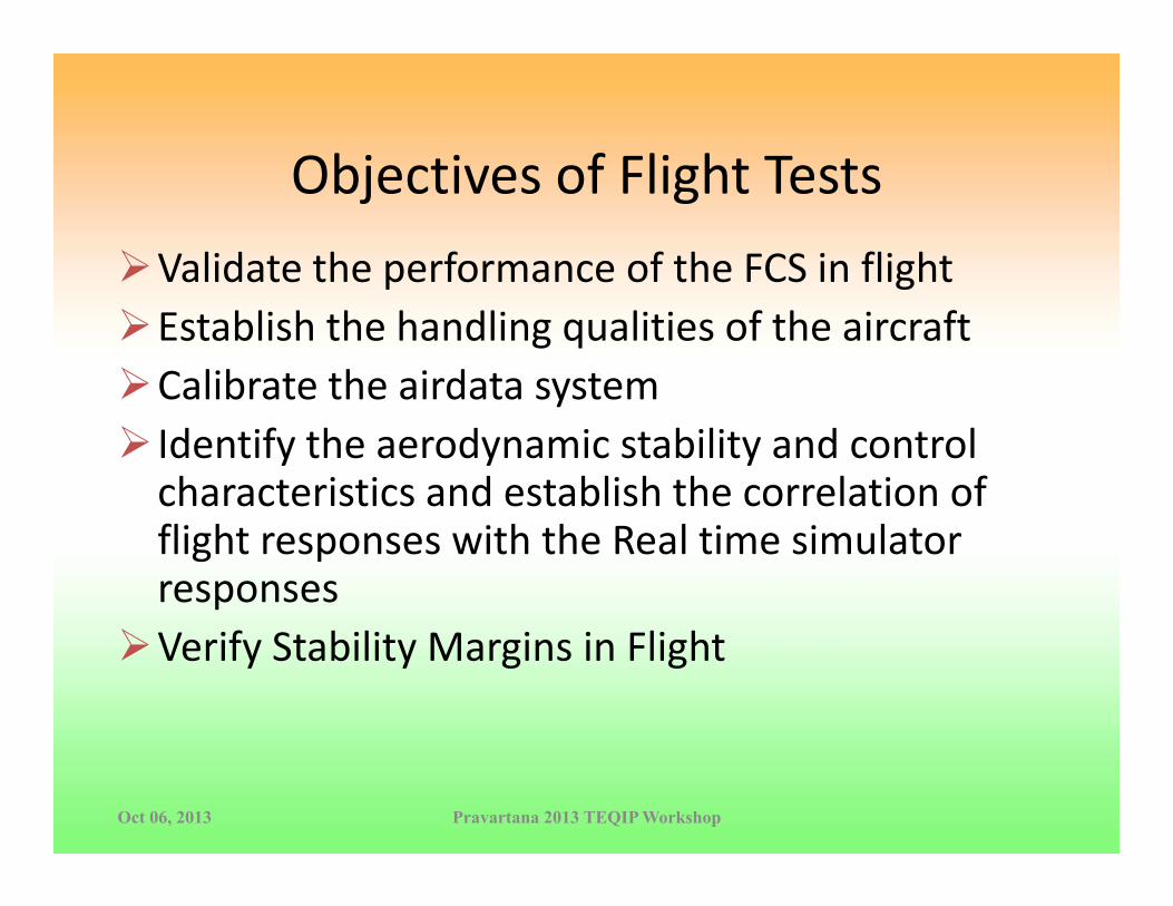
Objectives of Flight TestsObjectives of Flight TestsValidate the performance of the FCS in flightValidate the performance of the FCS in flightEstablish the handling qualities of the aircraftCalibrate the airdata systemCalibrate the airdata systemIdentify the aerodynamic stability and control characteristics and establish the correlation of flight responses with the Real time simulator responsesVerify Stability Margins in Flight
Oct 06, 2013 Pravartana 2013 TEQIP Workshop
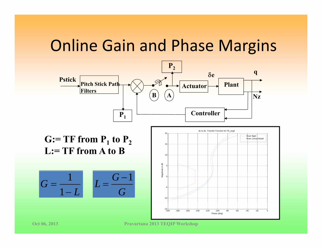
Online Gain and Phase MarginsOnline Gain and Phase MarginsP2 qδe
A
Pitch Stick Path Filters
Pstick
BPlant
NzActuator
ControllerP1
20
de to de -Transfer Function for F8_seg4
From flightFrom Linear ModelG:= TF from P to P
5
10
15
ude
in d
B
G:= TF from P1 to P2 L:= TF from A to B
LG
−=
11
-10
-5
0Mag
nitu
GGL 1−
=
Oct 06, 2013 Pravartana 2013 TEQIP Workshop
-200 -180 -160 -140 -120 -100 -80 -60 -40 -20 0-15
Phase (deg)

Modern Robust Control Applied to LCA lControl Laws
• Major Bottleneck:– Classical Gain and Phase
1
20
Margins still the onlyRobustness Criterion used
Open loop transfer function
0
5
10
15
itude
indB
Margin Template
for Flight Controllers (MIL Spec)
-15
-10
-5
0
Mag
ni
– Led to conservative H∞/μcontrollers
.
-250 -200 -150 -100 -50 0-15
Phase (deg)
Oct 06, 2013 Pravartana 2013 TEQIP Workshop

Robust, fragile, or optimal?Robust, fragile, or optimal?, Keel, L.H.; Bhattacharyya, S.P.IEEE Transactions on Automatic Control, Volume 42, Issue 8, Aug 1997 Page(s):1098 - 1105
CC+
-c yue P
Summary: We show by examples that optimum and robust controllers, designed by using theH2, H∞, l1, and μ formulations, can produce extremely fragile controllers, in the sense thatvanishingly small perturbations of the coefficients of the designed controller destabilize theclosed-loop control system. The examples show that this fragility usually manifests itself asextremely poor gain and phase margins of the closed-loop system. The calculations given hereshould raise a cautionary note and draw attention to the larger issue of controller sensitivitywhich may be important in other nonoptimal design techniques as well

Margin Requirementsg q
Gain ImRigid
Structural
Phase-1
Re
Nichols Plot Nyquist Plot
RigidStructural
yq

Margins Template Converted to U t i t th Pl tUncertainty on the Plant (Non Conservative)
|L(jω)| in dB|L(jω)| in dB
+6dB
-1800, 0 dB
∠|L(jω)|∠|L(jω)|
-1450-1800, 0 dB
∠|L(jω)|-6dB
6dB 350 template in theThe template converted to an
ncertaint on the plant6dB-350 template in the Nichols Plot
uncertainty on the plant

Margins and Complementary Sensitivity
Th B i D i P bl b th t fThe Basic Design Problem becomes that ofminimizing sensitivity for the nominal plant subjectto a bound on the biased complementarysensitivity.
10CP +c yu
z1
PΔ
0.25e1
75.01
25.11 0
0 <+ ∞CP
CP
C
-yu
P0
“A Modern Look at Gain and Phase Margins: An H∞/μ Approach”,AIAA Guidance Navigation and Control Conference, ControlTheory Analysis and Design, Boston, August 10-12, 1998, G. S.Theory Analysis and Design, Boston, August 10 12, 1998, G. S.Deodhare and V. V. Patel
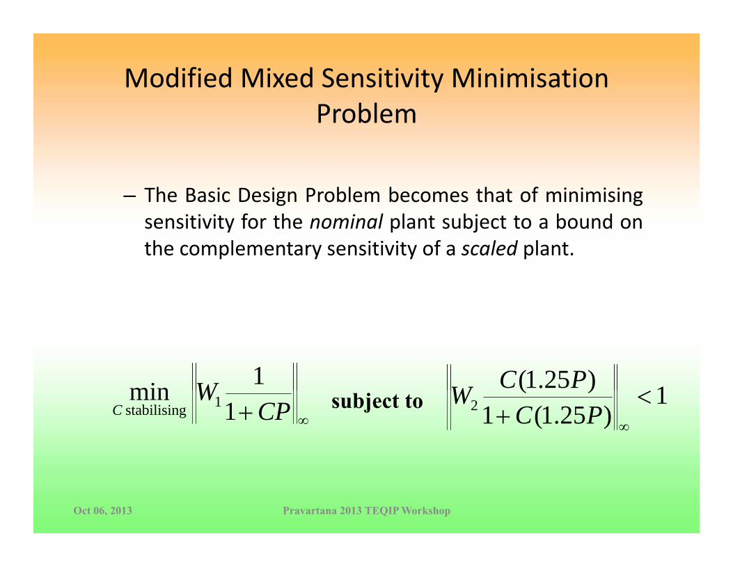
Modified Mixed Sensitivity Minimisation P blProblem
– The Basic Design Problem becomes that of minimisingsensitivity for the nominal plant subject to a bound onthe complementary sensitivity of a scaled plantthe complementary sensitivity of a scaled plant.
W 1min 1)25.1( PCW∞+ CP
WC 1
min 1gstabilisin 1
)25.1(1)(
2 <+ ∞PC
Wsubject to
Oct 06, 2013 Pravartana 2013 TEQIP Workshop

SolutionSolution
Th P bl “ l d” i it ti• The Problem was “solved” using an iterative procedure
+ )251(11min 1 PC
W i1
)251(1)25.1(
2 <+ PC
PCWs.t∞+ )25.1(1 PC
PCWW iii 1111
)25.1(1 −− +=
)25.1(1+ ∞PC
0 WW =where PCWW
i 111 1 −+
11
11 WW =where
Oct 06, 2013 Pravartana 2013 TEQIP Workshop
ε<+
−+ ∞−∞ PC
WPC
Wii 1
11 11
11
till

Oct 06, 2013 Pravartana 2013 TEQIP Workshop

Oct 06, 2013 Pravartana 2013 TEQIP Workshop
Utility in DesignUtility in Design
• Helps to benchmark a classical controller and findHelps to benchmark a classical controller and find “limits of performance”.
• Identify new structures for a classical controller ydesign.
• For the multivariable case the uncertainty can be yadded to each input of the plant ‐ μ synthesis for non‐conservative designs.
Oct 06, 2013 Pravartana 2013 TEQIP Workshop

Clearance of Flight Control LawsClearance of Flight Control Laws
• Clearance of control laws for flight – a very laborious g yprocess.
• Certification Authorities have to be shown that f f fl ll f h l haircraft is safe to fly in all parts of the envelope with
the nominal controller and with failures.• Safety to be ensured with all aerodynamic tolerances• Safety to be ensured with all aerodynamic tolerances and tolerances on airdata parameters.
• For all configurations of the aircraft – with different gcombinations of weapons, drop tanks, etc.
Oct 06, 2013 Pravartana 2013 TEQIP Workshop

Oct 06, 2013 Pravartana 2013 TEQIP Workshop

Utility of Modern Control Techniques f lfor Clearance
• Current approach is gridding of the envelopeCurrent approach is gridding of the envelope• Disadvantages‐
– Number of cases goes up exponentially as aNumber of cases goes up exponentially as a function of the parameters
– No guarantee of satisfaction of requirements at non‐grid points
– Only extreme values of tolerances considered
Oct 06, 2013 Pravartana 2013 TEQIP Workshop

Utility in Flight Clearance …Utility in Flight Clearance …
• Recent research b the GARTEUR• Recent research by the GARTEUR Group has demonstrated how the
l t iti it it i fcomplementary sensitivity criterion for stability margins can be used for
l t d fli ht laccelerated flight clearance• Achieved by modeling all the uncertainties in database as LFTs and using μ‐norms to clear the flight envelope.
Oct 06, 2013 Pravartana 2013 TEQIP Workshop
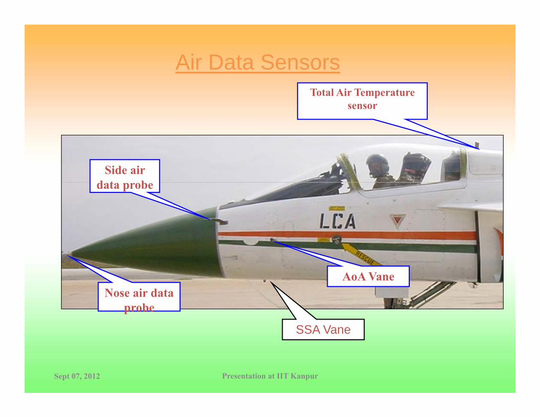
Air Data SensorsTotal Air Temperature
sensor
Side air d t bdata probe
AoA VaneNose air data
probe
SSA Vane
Sept 07, 2012 Presentation at IIT Kanpur

Concluding Remarks
Design of Control Systems with a human in the control loop is a very challenging problemloop is a very challenging problem
Flight Simulation plays a very important role in the design ti i tioptimization
A Good R&D Base has been established in the country to undertake
aircraft flight control design, , airdataairdata system algorithm developmentsystem algorithm developmentairdataairdata system algorithm development, system algorithm development, AerodataAerodata update and update and airdataairdata system calibration, system calibration, Flight testing and flight envelope expansion. Flight testing and flight envelope expansion.
Sept 07, 2012 Presentation at IIT Kanpur

Control Law Flying on LCA
Thank You Theory - without Practice - is Sterile; Practice - without Theory - is BlindPractice without Theory is Blind-- Karl Marx

AcknowledgementAcknowledgement
This presentation is a summary of the outstanding contributions
made by the National Control Law Team scientists from
NAL, ADA and HALOct 06, 2013 Pravartana 2013 TEQIP Workshop