channel configuration-siemens
TRANSCRIPT

Channel Configuration Siemens
MN1789EU07MN_00011
Contents
1 Channel Configuration Overview 3
2 Control Channel Configuration 13
2.1 Dedicated Channels 14
2.2 Random Access Channel 16
2.3 Paging / Access Grant and Notification-Channel 23
2.4 CCCH Load 25
3 Extended Channel Mode 29
4 Exercise 31
5 Solution 35
Channel Configuration
Siemens Channel Configuration
MN1789EU07MN_00012
Channel Configuration Siemens
MN1789EU07MN_00013
1 Channel Configuration Overview
Siemens Channel Configuration
MN1789EU07MN_00014
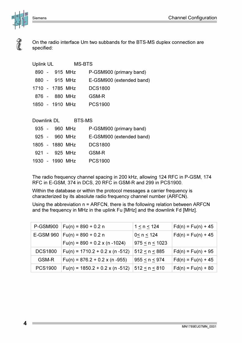
On the radio interface Um two subbands for the BTS-MS duplex connection arespecified:
Uplink UL MS-BTS
890 - 915 MHz P-GSM900 (primary band)
880 - 915 MHz E-GSM900 (extended band)
1710 - 1785 MHz DCS1800
876 - 880 MHz GSM-R
1850 - 1910 MHz PCS1900
Downlink DL BTS-MS
935 - 960 MHz P-GSM900 (primary band)
925 - 960 MHz E-GSM900 (extended band)
1805 - 1880 MHz DCS1800
921 - 925 MHz GSM-R
1930 - 1990 MHz PCS1900
The radio frequency channel spacing in 200 kHz, allowing 124 RFC in P-GSM, 174RFC in E-GSM, 374 in DCS, 20 RFC in GSM-R and 299 in PCS1900.
Within the database or within the protocol messages a carrier frequency ischaracterized by its absolute radio frequency channel number (ARFCN).
Using the abbreviation n = ARFCN, there is the following relation between ARFCNand the frequency in MHz in the uplink Fu [MHz] and the downlink Fd [MHz].
P-GSM900 Fu(n) = 890 + 0.2 n 1 < n < 124 Fd(n) = Fu(n) + 45
E-GSM 960 Fu(n) = 890 + 0.2 n
Fu(n) = 890 + 0.2 x (n -1024)
0< n < 124
975 < n < 1023
Fd(n) = Fu(n) + 45
DCS1800 Fu(n) = 1710.2 + 0.2 x (n -512) 512 < n < 885 Fd(n) = Fu(n) + 95
GSM-R Fu(n) = 876.2 + 0.2 x (n -955) 955 < n < 974 Fd(n) = Fu(n) + 45
PCS1900 Fu(n) = 1850.2 + 0.2 x (n -512) 512 < n < 810 Fd(n) = Fu(n) + 80
Channel Configuration Siemens
MN1789EU07MN_00015
. . . . . . . . . . . . . . . . . . . . . . . . . . . . . . . . . . .
. . . . . . . . . . . . . . . . . . . . . . . . . . . . . . . . . . .
. . . . . . . . . . . . . . . . . . . . . . . . . . . . . . . . . . .
. . . . . . . . . . . . . . . . . . . . . . . . . . . . . . . . . . .
. . . . . . . . . . . . . . . . . . . . . . . . . . . . . . . . . . .
. . . . . . . . . . . . . . . . . . . . . . . . . . . . . . . . . . .
. . . . . . . . . . . . . . . . . . . . . . . . . . . . . . . . . . .
. . . . . . . . . . . . . . . . . . . . . . . . . . . . . . . . . . .
. . . . . . . . . . . . . . . . . . . . . . . . . . . . . . . . . . .
. . . . . . . . . . . . . . . . . . . . . . . . . . . . . . . . . . .
. . . . . . . . . . . . . . . . . . . . . . . . . . . . . . . . . . .
. . . . . . . . . . . . . . . . . . . . . . . . . . . . . . . . . . .
. . . . . . . . . . . . . . . . . . . . . . . . . . . . . . . . . . .
. . . . . . . . . . . . . . . . . . . . . . . . . . . . . . . . . . .
. . . . . . . . . . . . . . . . . . . . . . . . . . . . . . . . . . .
. . . . . . . . . . . . . . . . . . . . . . . . . . . . . . . . . . .
. . . . . . . . . . . . . . . . . . . . . . . . . . . . . . . . . . .
. . . . . . . . . . . . . . . . . . . . . . . . . . . . . . . . . . .
. . . . . . . . . . . . . . . . . . . . . . . . . . . . . . . . . . .
. . . . . . . . . . . . . . . . . . . . . . . . . . . . . . . . . . .
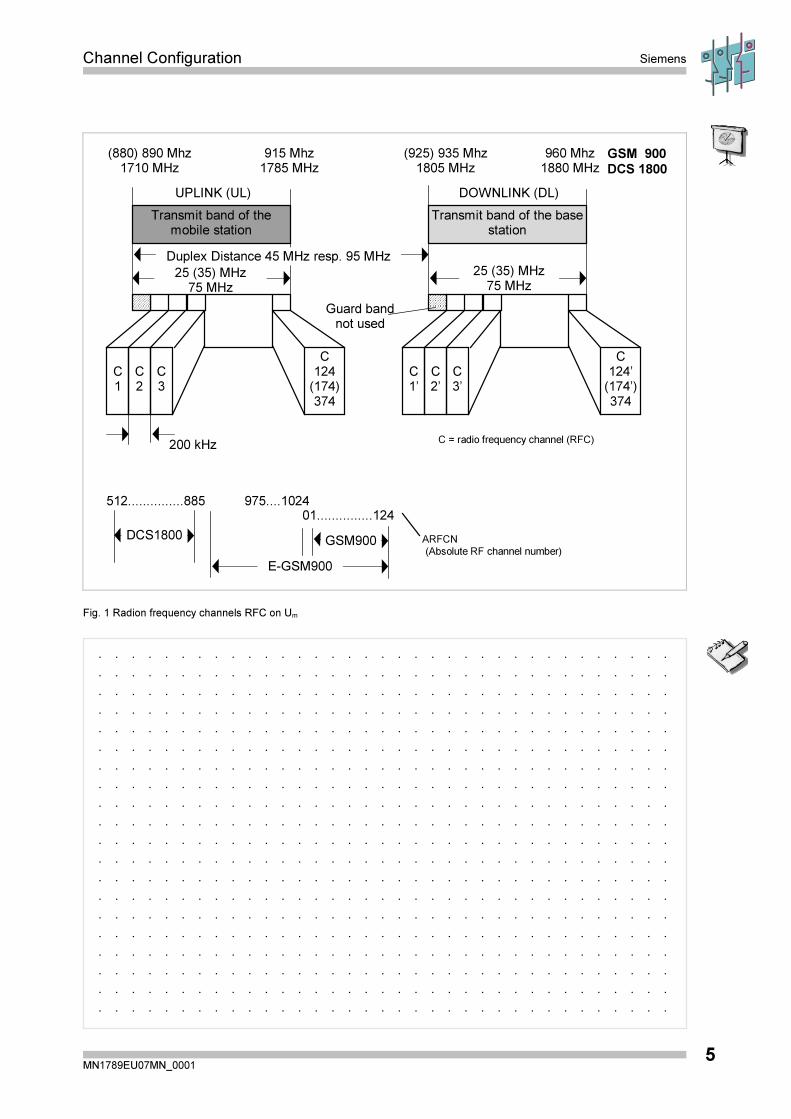
25 (35) MHz75 MHz
UPLINK (UL)
915 Mhz1785 MHz
(880) 890 Mhz1710 MHz
Transmit band of themobile station
C124
(174)374
C3
C2
C1
200 kHz
DOWNLINK (DL)
GSM 900
DCS 1800
960 Mhz1880 MHz
01...............124512...............885 975....1024
ARFCN(Absolute RF channel number)
C = radio frequency channel (RFC)
Guard bandnot used
(925) 935 Mhz1805 MHz
Transmit band of the basestation
C124’
(174’)374
C3’
C2’
C1’
25 (35) MHz75 MHz
Duplex Distance 45 MHz resp. 95 MHz
E-GSM900
GSM900DCS1800
Fig. 1 Radion frequency channels RFC on Um

Siemens Channel Configuration
MN1789EU07MN_00016
Each RFC offers 8 physical channels a time division multiplex access TDMA.
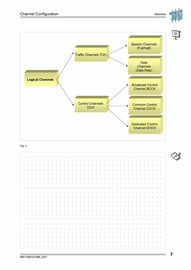
The physical channels are subdivided into logical channels, divided in traffic channelsand control channels according GSM 04.03.
200 kHzTime
0
43
21
07
65
43
21
4,615 msec
= 8 � 577 µs
Fig. 2 Radio frequency channels RFC on Um
Channel Configuration Siemens
MN1789EU07MN_00017
. . . . . . . . . . . . . . . . . . . . . . . . . . . . . . . . . . .
. . . . . . . . . . . . . . . . . . . . . . . . . . . . . . . . . . .
. . . . . . . . . . . . . . . . . . . . . . . . . . . . . . . . . . .
. . . . . . . . . . . . . . . . . . . . . . . . . . . . . . . . . . .
. . . . . . . . . . . . . . . . . . . . . . . . . . . . . . . . . . .
. . . . . . . . . . . . . . . . . . . . . . . . . . . . . . . . . . .
. . . . . . . . . . . . . . . . . . . . . . . . . . . . . . . . . . .
. . . . . . . . . . . . . . . . . . . . . . . . . . . . . . . . . . .
. . . . . . . . . . . . . . . . . . . . . . . . . . . . . . . . . . .
. . . . . . . . . . . . . . . . . . . . . . . . . . . . . . . . . . .
. . . . . . . . . . . . . . . . . . . . . . . . . . . . . . . . . . .
. . . . . . . . . . . . . . . . . . . . . . . . . . . . . . . . . . .
. . . . . . . . . . . . . . . . . . . . . . . . . . . . . . . . . . .
. . . . . . . . . . . . . . . . . . . . . . . . . . . . . . . . . . .
. . . . . . . . . . . . . . . . . . . . . . . . . . . . . . . . . . .
. . . . . . . . . . . . . . . . . . . . . . . . . . . . . . . . . . .
. . . . . . . . . . . . . . . . . . . . . . . . . . . . . . . . . . .
. . . . . . . . . . . . . . . . . . . . . . . . . . . . . . . . . . .
. . . . . . . . . . . . . . . . . . . . . . . . . . . . . . . . . . .
. . . . . . . . . . . . . . . . . . . . . . . . . . . . . . . . . . .
. . . . . . . . . . . . . . . . . . . . . . . . . . . . . . . . . . .
Speech Channels
(Full/Half)
Data
Channels
(Data Rate)
Control Channels
CCH
Traffic Channels TCH
Logical Channels
Broadcast Control
Channel BCCH
Dedicated Control
Channel DCCH
Common Control
Channel CCCH
Fig. 3
Siemens Channel Configuration
MN1789EU07MN_00018
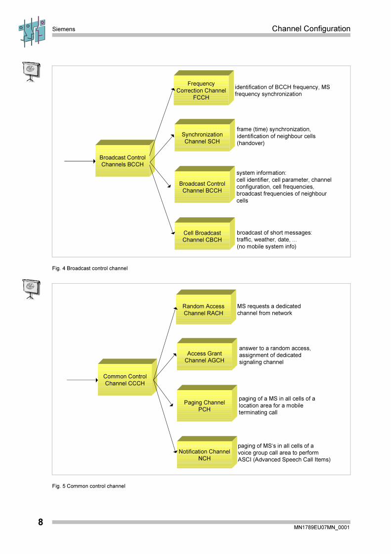
Broadcast ControlChannel BCCH
Cell BroadcastChannel CBCH
Synchronization
Channel SCH
Frequency
Correction Channel
FCCH
Broadcast ControlChannels BCCH
system information:
cell identifier, cell parameter, channel
configuration, cell frequencies,broadcast frequencies of neighbour
cells
broadcast of short messages:traffic, weather, date, ...
(no mobile system info)
frame (time) synchronization,
identification of neighbour cells
(handover)
identification of BCCH frequency, MSfrequency synchronization
Fig. 4 Broadcast control channel
Paging ChannelPCH
Notification ChannelNCH
Access GrantChannel AGCH
Random Access
Channel RACH
Common Control
Channel CCCH
paging of a MS in all cells of a
location area for a mobileterminating call
paging of MS‘s in all cells of avoice group call area to performASCI (Advanced Speech Call Items)
answer to a random access,assignment of dedicated
signaling channel
MS requests a dedicatedchannel from network
Fig. 5 Common control channel
Channel Configuration Siemens
MN1789EU07MN_00019
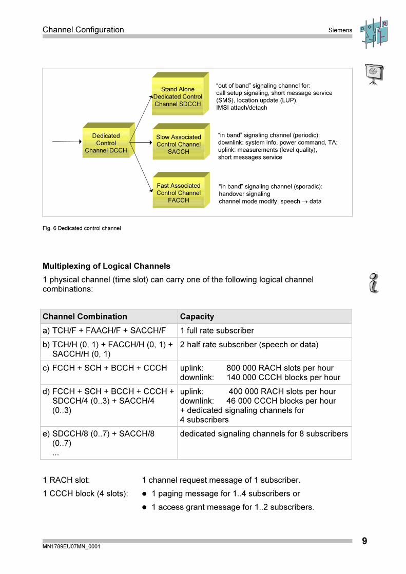
Fast Associated
Control Channel
FACCH
Slow Associated
Control Channel
SACCH
Stand Alone
Dedicated Control
Channel SDCCH
Dedicated
Control
Channel DCCH
“in band” signaling channel (periodic):
downlink: system info, power command, TA;
uplink: measurements (level quality),
short messages service
“out of band” signaling channel for:
call setup signaling, short message service
(SMS), location update (LUP),
IMSI attach/detach
“in band” signaling channel (sporadic):
handover signaling
channel mode modify: speech � data
Fig. 6 Dedicated control channel
Multiplexing of Logical Channels
1 physical channel (time slot) can carry one of the following logical channelcombinations:
Channel Combination Capacity
a) TCH/F + FAACH/F + SACCH/F 1 full rate subscriber
b) TCH/H (0, 1) + FACCH/H (0, 1) +SACCH/H (0, 1)
2 half rate subscriber (speech or data)
c) FCCH + SCH + BCCH + CCCH uplink: 800 000 RACH slots per hourdownlink: 140 000 CCCH blocks per hour
d) FCCH + SCH + BCCH + CCCH +SDCCH/4 (0..3) + SACCH/4(0..3)
uplink: 400 000 RACH slots per hourdownlink: 46 000 CCCH blocks per hour+ dedicated signaling channels for4 subscribers
e) SDCCH/8 (0..7) + SACCH/8(0..7)...
dedicated signaling channels for 8 subscribers
1 RACH slot: 1 channel request message of 1 subscriber.
1 CCCH block (4 slots): � 1 paging message for 1..4 subscribers or
� 1 access grant message for 1..2 subscribers.
Siemens Channel Configuration
MN1789EU07MN_000110
Channel Organization in a Cell
In SBS BR2.1 the following channel combinations are allowed:
� TCH/F + FACCH/F + SACCH/F TCHFULL
� FCCH + SCH+ BCCH+ CCCH (AGCH + PCH + RACH) MAINBCCH
� FCCH + SCH + BCCH + CCCH + 4 (SDCCH + SACCH) MBCCHC
� 8 (SDCCH + SACCH) SDCCH
Additional channel combinations in SBS BR3.0 :
� TCH/H (0) + FACCH/H (0) + SACCH/H (0) + TCH/H (1) TCHF_HLF
� FCCH + SCH + BCCH + CCCH + 3 (SDCCH + SACCH) + CBCH BCBCH
� 7 (SDCCH + SACCH) + CBCH SCBCH
� BCCH + CCCH CCCH
In a cell with a single RFC the allocation should be the following:
Timeslot 0 � FCCH+SCH + BCCH + CCCH + 4 (SDCCH + SACCH)
Timeslot 1...7 � TCH/F + FACCH/F + SACCH/F
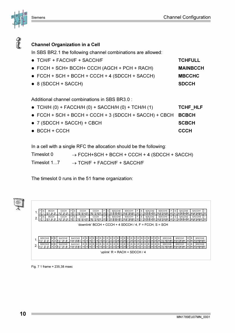
The timeslot 0 runs in the 51 frame organization:
S
11
S
1
F
10
F
0
BCCH
2 3 4 5
CCCH
6 7 8 9
CCCH
12 13 14 15
CCCH
16 17 18 19
S
21
S
31
F
30
F
20
SDCCH0
22 23 24 25
SDCCH1
26 27 28 29
SDCCH2
32 33 34 35
SDCCH3
36 37 38 39
S
41
I
50
F
40
SACCH0
42 43 44 45
SACCH1
46 47 48 49
1.
1.
S
11
S
1
F
10
F
0
BCCH
2 3 4 5
CCCH
6 7 8 9
CCCH
12 13 14 15
CCCH
16 17 18 19
S
21
S
31
F
30
F
20
SDCCH0
22 23 24 25
SDCCH1
26 27 28 29
SDCCH2
32 33 34 35
SDCCH3
36 37 38 39
S
41
I
50
F
40
SACCH2
42 43 44 45
SACCH3
46 47 48 492.
‘uplink’ R = RACH + SDCCH / 4
‘downlink’ BCCH + CCCH + 4 SDCCH / 4, F = FCCH, S = SCH
R
5
R
4
SDCCH3
0 1 2 3
SACCH2
6 7 8 9
SACCH3
10 11 1213
R
15
R
14
R
17
R
16
R
19
R
18
R
21
R
20
R
23
R
22
R
25
R
24
R
27
R
26
R
29
R
28
R
31
R
30
R
33
R
32
R
36
R
35
R
34
SDCCH0
37 38 39 40
SDCCH1
41 42 43 44
R
46
R
45
SDCCH2
47 48 49 50
2.R
5
R
4
SDCCH3
0 1 2 3
SACCH0
6 7 8 9
SACCH1
10 11 1213
R
15
R
14
R
17
R
16
R
19
R
18
R
21
R
20
R
23
R
22
R
25
R
24
R
27
R
26
R
29
R
28
R
31
R
30
R
33
R
32
R
36
R
35
R
34
SDCCH0
37 38 39 40
SDCCH1
41 42 43 44
R
46
R
45
SDCCH2
47 48 49 50
Fig. 7 1 frame = 235,38 msec
Channel Configuration Siemens
MN1789EU07MN_000111
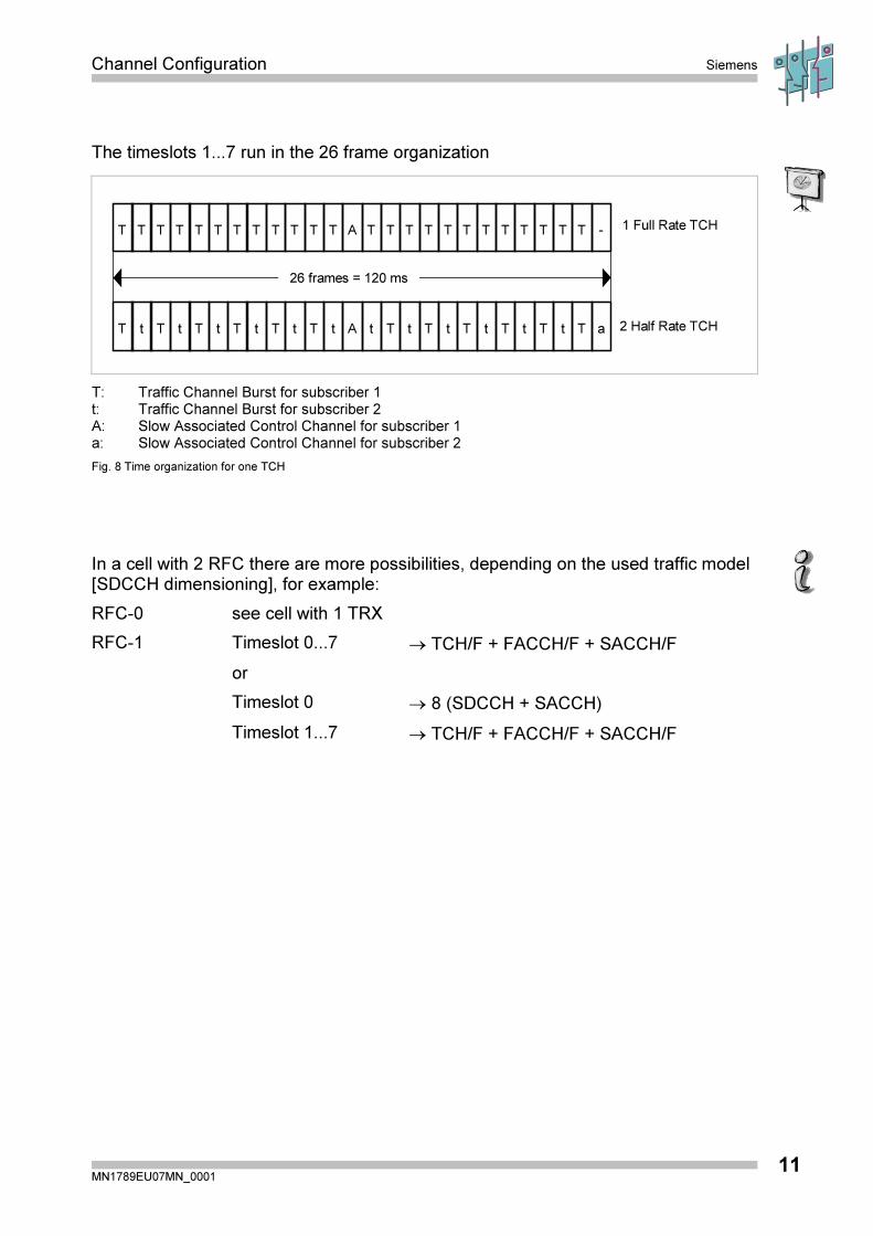
The timeslots 1...7 run in the 26 frame organization
TT TT TT TT TT TT A TT TT TT TT TT -TT
t 2 Half Rate TCH
1 Full Rate TCH
26 frames = 120 ms
T tT tT tT tT tT A Tt Tt Tt Tt Tt aTt
T: Traffic Channel Burst for subscriber 1t: Traffic Channel Burst for subscriber 2A: Slow Associated Control Channel for subscriber 1a: Slow Associated Control Channel for subscriber 2
Fig. 8 Time organization for one TCH
In a cell with 2 RFC there are more possibilities, depending on the used traffic model[SDCCH dimensioning], for example:
RFC-0 see cell with 1 TRX
RFC-1 Timeslot 0...7 � TCH/F + FACCH/F + SACCH/F
or
Timeslot 0 � 8 (SDCCH + SACCH)
Timeslot 1...7 � TCH/F + FACCH/F + SACCH/F
Siemens Channel Configuration
MN1789EU07MN_000112
Channel Configuration Siemens
MN1789EU07MN_000113
2 Control Channel Configuration
Siemens Channel Configuration
MN1789EU07MN_000114
Introduction:
In a MOC, MTC, LU the MS has to request an SDCCH using the RACH. There is atime delay between the request and the SDCCH allocation due to the traffic load. Ifthere is a free SDCCH, it is allocated using the AGCH. The SDCCH is used for theauthentication, transmission of cipher parameters and call initialization. Next a trafficchannel is requested and allocated, if available. After this, the SDCCH is released.The MS acknowledges the allocation on the FACCH. The TCH with its FACCH andSACCH is occupied until the end of the call. So the blocking probability is a functionof
� availability of SDCCH
� availability of TCH
� waiting time in TCH queue, if queuing performed (BTS parameter)
� time for connection establishment.
2.1 Dedicated Channels
If we evaluate a given traffic model, we find a certain traffic load per subscriber.Additionally we have to calculate the SDCCH load per subscriber.
According to the traffic model given in appendix-C, there are four values to beconsidered:
� call attempts per subscriber per hour 1.1
� time for MOC/MTC setup signaling 3 sec
� time for Location Update 5 sec
� location updates per subscriber per hour 2.2.
The SDCCH load per subscriber is calculated as follows:
(1.1 * 3 sec + 2.2 * 5 sec) / 3600 sec = 0.004 Erl.
Furthermore we have for the TCH: 25 mErl.
At the following page an example for a channel configuration of a 2 carrier cellsis given using the assumptions above.

Channel Configuration Siemens
MN1789EU07MN_000115
Example for Channel Configuration
Assumptions: 25 mErl TCH Load per subscriber
4 mErl SDCCH load per subscriber
no load problem on CCCH (refer to chapter 1.2.4)
Cell with 2 TRX: 16 channels
Configuration A Configuration B
� 1 comb. CCCH/SDCCH � 4 SDCCH
� 15 TCH
� uncomb. CCCH
� 1 SDCCH/8 � 8 SDCCH
� 14 TCH
offered TCH load at 1 % blocking
8.11 Erl � Subscriber 8.11 / 0.025 = 324
offered TCH load at 1 % blocking
7.35 Erl � Subscriber: 7.35 / 0.025 = 294
offered SDCCH load at 1 % blocking
0.87 Erl � Subscriber 0.87 / 0.004 = 218
offered SDCCH load at 1 % blocking
3.13 Erl � Subscriber: 3.13 / 0.004 = 782
���� SDCCH limited: 218 subscriber ���� TCH limited: 294 subscriber
���� Configuration B is the better one for this scenario.
Siemens Channel Configuration
MN1789EU07MN_000116
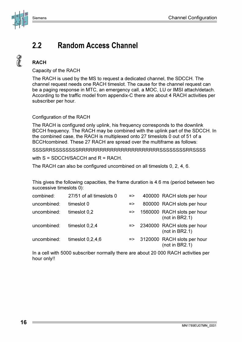
2.2 Random Access Channel
RACH
Capacity of the RACH
The RACH is used by the MS to request a dedicated channel, the SDCCH. Thechannel request needs one RACH timeslot. The cause for the channel request canbe a paging response in MTC, an emergency call, a MOC, LU or IMSI attach/detach.According to the traffic model from appendix-C there are about 4 RACH activities persubscriber per hour.
Configuration of the RACH
The RACH is configured only uplink, his frequency corresponds to the downlinkBCCH frequency. The RACH may be combined with the uplink part of the SDCCH. Inthe combined case, the RACH is multiplexed onto 27 timeslots 0 out of 51 of aBCCHcombined. These 27 RACH are spread over the multiframe as follows:
SSSSRRSSSSSSSSRRRRRRRRRRRRRRRRRRRRRRRSSSSSSSSRRSSSS
with S = SDCCH/SACCH and R = RACH.
The RACH can also be configured uncombined on all timeslots 0, 2, 4, 6.
This gives the following capacities, the frame duration is 4.6 ms (period between twosuccessive timeslots 0):
combined: 27/51 of all timeslots 0 => 400000 RACH slots per hour
uncombined: timeslot 0 => 800000 RACH slots per hour
uncombined: timeslot 0,2 => 1560000 RACH slots per hour(not in BR2.1)
uncombined: timeslot 0,2,4 => 2340000 RACH slots per hour(not in BR2.1)
uncombined: timeslot 0,2,4,6 => 3120000 RACH slots per hour(not in BR2.1)
In a cell with 5000 subscriber normally there are about 20 000 RACH activities perhour only!!

Channel Configuration Siemens
MN1789EU07MN_000117
RACH Control Parameter
RACH busy threshold, defines a threshold for the signal level during the RACHbursts. The BTS measures the signal level on each RACH timeslot and determineswhether a channel request is successfully received or not: If the received signal levelis greater than or equal to the value of RACHBT then the RACH burst in question willbe indicated as busy (one or more mobile stations have tried to access the network).The purpose of this parameter is to avoid unnecessary load on the BSS by normalnoise signals being decoded as RACH bursts (followed by seizure of SDCCH) bymistake. However, to be on the safe side the BTS does not only evaluate the RACHlevel but additionally decodes the Synch sequence bits of the RACH burst.
Note: The value entered for this parameter is not only relevant for the CHANNELREQUEST message on the RACH but also for the HANDOVER ACCESSmessage on the FACCH!
The MS receives the RACH control parameters from the base station on the BCCH:
� Maximum number of retransmission ( max_retrans ) MAXRETR = 1, 2, 4, 7.
If a channel request is not acknowledged by the base station, the MS repeats therequest until the given value of MAXRETR.
� Number of slots to spread transmissions ( tx_integer ) NSLOTST = 0,..15representing the real values
of 3, 4, 5, 6, 7, 8, 9, 10, 11, 12, 14, 16, 20, 25, 32, 50.
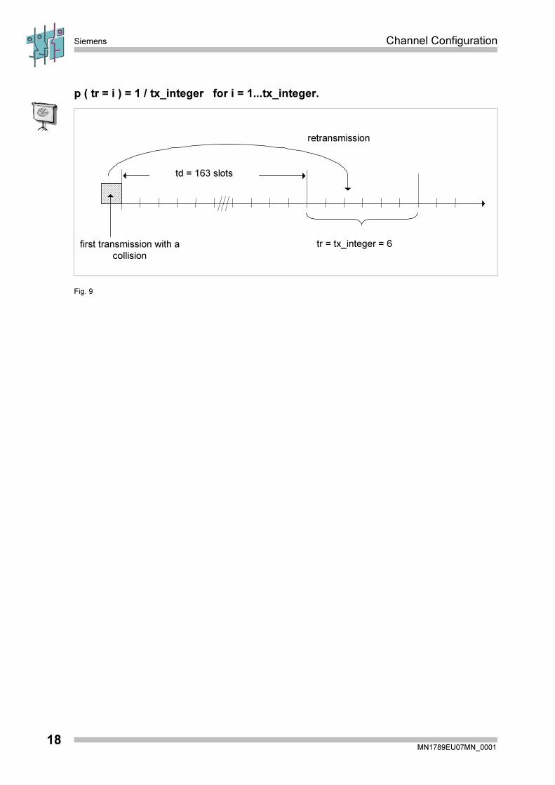
This value determines the time period between sending of two channel requests. Thisperiod is measured in RACH slots and is the sum of a deterministic part td and arandom part tr:
MS tx_integer td (RACH slots,
combined)
td (RACH slots,
uncombined)
Phase 1 ----- 41 (0.35 sec) 55 (0.25 sec)
3, 8, 14, 50 41 (0.35 sec) 55 (0.25 sec)
4, 9, 16 52 (0.45 sec) 76 (0.35 sec)
Phase 2 5, 10, 20 58 (0.50 sec) 109 (0.50 sec)
6, 11, 25 86 (0.75 sec) 163(0.75 sec)
7, 12, 32 115 (1.00 sec) 217(1.00 sec)
Deterministic part td of retransmission period as a function of tx_integer.
The random part tr is an integer between 1 and tx_integer where the probability ofchoosing a certain time slot i is given by:
Siemens Channel Configuration
MN1789EU07MN_000118
p ( tr = i ) = 1 / tx_integer for i = 1...tx_integer.
tr = tx_integer = 6
retransmission
td = 163 slots
first transmission with a
collision
Fig. 9

Channel Configuration Siemens
MN1789EU07MN_000119
Immediate Assignment Procedure:
The procedure is specified in GSM 04.08, chapter 3.3.1.2:
Select RACH slot for
next transmission,
wait for grant
set timer T3126
wait for grant
WAIT
T3122
SDCCH
Allocation
N
Y
Y
N
N
Y
number of
retransmissions + 1
number of
retransmissions = 0
Select RACH slot
for first transmission
IMMEDIATE
ASSIGNMENT
PROCEDURE
no.of
retransmissions
= max_retrans
immediate
assignment
Send CHANNEL
REQUEST msg.
GRANT during
Sup. time
Rejection
CELL
RESELECTION
N
Y
Fig. 10 Immediate assignment procedure
Siemens Channel Configuration
MN1789EU07MN_000120
Evaluation of Immediate Assignment Procedure for different parameter values
Traffic Load/RACH Activities per Hour
The relative traffic load is the average number of initiated immediate assignmentprocedures or RACH activities in a timeslot:
traffic load =total number of immediate assignment procedures / total number of RACH slots.
The absolute number of RACH activities per hour is obtained by multiplying thisrelative load with the number of RACH slots per hour.
Blocking
The blocking shows the percentage of not successful immediate assignmentprocedures initialized by the MS.
blocking [%] =(number of unsucc. imm. ass. proc. / total number of imm. ass. Proc. ) * 100.
Throughput
The channel throughput is the average number of successful transmissions per timeslot.
throughput = number of successful transmissions/number of simulated time slots.
throughput = ( 1 - blocking ) * traffic load.
Wait Time
The wait time is the time between the initiation of the immediate assignmentprocedure and the arrival of the immediate assignment message. For the waiting timeit is useful to consider the 90% quantile of the wait time:
for 90% of the immediate assignment procedures, the wait time is less than the timet90.
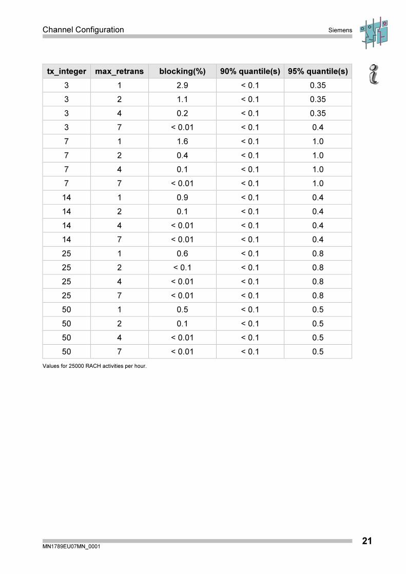
The blocking and the 90% (95%) quantile for different values of the RACH controlparameters is shown in the following tables for a combined RACH/SDCCH:
Channel Configuration Siemens
MN1789EU07MN_000121
tx_integer max_retrans blocking(%) 90% quantile(s) 95% quantile(s)
3 1 2.9 < 0.1 0.35
3 2 1.1 < 0.1 0.35
3 4 0.2 < 0.1 0.35
3 7 < 0.01 < 0.1 0.4
7 1 1.6 < 0.1 1.0
7 2 0.4 < 0.1 1.0
7 4 0.1 < 0.1 1.0
7 7 < 0.01 < 0.1 1.0
14 1 0.9 < 0.1 0.4
14 2 0.1 < 0.1 0.4
14 4 < 0.01 < 0.1 0.4
14 7 < 0.01 < 0.1 0.4
25 1 0.6 < 0.1 0.8
25 2 < 0.1 < 0.1 0.8
25 4 < 0.01 < 0.1 0.8
25 7 < 0.01 < 0.1 0.8
50 1 0.5 < 0.1 0.5
50 2 0.1 < 0.1 0.5
50 4 < 0.01 < 0.1 0.5
50 7 < 0.01 < 0.1 0.5
Values for 25000 RACH activities per hour.
Siemens Channel Configuration
MN1789EU07MN_000122
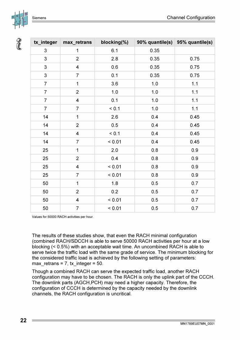
tx_integer max_retrans blocking(%) 90% quantile(s) 95% quantile(s)
3 1 6.1 0.35
3 2 2.8 0.35 0.75
3 4 0.6 0.35 0.75
3 7 0.1 0.35 0.75
7 1 3.6 1.0 1.1
7 2 1.0 1.0 1.1
7 4 0.1 1.0 1.1
7 7 < 0.1 1.0 1.1
14 1 2.6 0.4 0.45
14 2 0.5 0.4 0.45
14 4 < 0.1 0.4 0.45
14 7 < 0.01 0.4 0.45
25 1 2.0 0.8 0.9
25 2 0.4 0.8 0.9
25 4 < 0.01 0.8 0.9
25 7 < 0.01 0.8 0.9
50 1 1.8 0.5 0.7
50 2 0.2 0.5 0.7
50 4 < 0.01 0.5 0.7
50 7 < 0.01 0.5 0.7
Values for 50000 RACH activities per hour.
The results of these studies show, that even the RACH minimal configuration(combined RACH/SDCCH is able to serve 50000 RACH activities per hour at a lowblocking (< 0.5%) with an acceptable wait time. An uncombined RACH is able toserve twice the traffic load with the same grade of service. The minimum blocking forthe considered traffic load is achieved by the following setting of parameters:max_retrans = 7, tx_integer = 50.
Though a combined RACH can serve the expected traffic load, another RACHconfiguration may have to be chosen. The RACH is only the uplink part of the CCCH.The downlink parts (AGCH,PCH) may need a higher capacity. Therefore, theconfiguration of CCCH is determined by the capacity needed by the downlinkchannels, the RACH configuration is uncritical.
Channel Configuration Siemens
MN1789EU07MN_000123
2.3 Paging / Access Grant and Notification-Channel
PCH/AGCH
The paging channel and the access grant channel share the same TDMA framemapping (modulo 51) when combined onto a basic physical channel. The channelsare shared on a block by block basis. The information within each block allows theMS to determine if it is a paging or an access grant message. Every paging channelcan be used by the system as access grant channel but it is not allowed to thesystem to use access grant channels as paging channels. However, to ensure amobile a satisfactory access to the system, there is a control parameter to define afixed number of access grant blocks in the 51 multiframe. The number of blocksreserved for AGCH is broadcasted on the BCH. The number of available pagingblocks is reduced by this number.
Paging channels may be used as access grant channels but not vice versa.Therefore it is useful to set the parameter BS_AG_BLKS_RES to the smallest valueand let the system organize the use of channels. In case of MOC more AGCH areneeded, in case of MTC more PCH are needed. In average the number of MOC ishigher than the number of MTC. If the BS_AG_BLKS_RES value is set too high withthe result of a PCH shortage, a overload indication for the PCH may arise in hightraffic time.
In GSM traffic model the paging per subscriber per hour is 0.93.
The second parameter to be set is called BS_PA_MFRMS ( value = 2..9, number ofmultiframes between paging). It indicates the number of TDMA multiframes betweentransmission of paging messages to the same paging subgroup. The MS gets theinformation on BCH, to which paging groups it should listen to. By this way the MScan save battery because it only listens to its own paging group. If the value is toohigh so that the time between two blocks of the same paging sub-channel is high, thetime for setting up an MTC is high.
Siemens Channel Configuration
MN1789EU07MN_000124
In a medium cell the common channel pattern on timeslot 0 on one of the TRX canuse the following combination downlink (in uplink all channels are used as RACH):
FSBBBBPPPPFSPPPPPPPPFSPPPPPPPPFSPPPPPPPPFSPPPPPPPP
F = FCCH
S = SCH
B = BCCH
P = PACH/AGCH.
An example for the load and the servable number of subscribers is given at thefollowing pages.
NCH
In all cells where the ASCI service is enabled, a new logical channel belonging toCCCH is defined, this new downlink channel is the Notification Channel (NCH).An MS which is VBS/VGCS* subscriber, besides the paging blocks, monitors also theNotification Channel. This logical channel is mapped onto contiguous blocks reservedfor access grants, the position and the number of blocks are defined by the twoparameters NCH_FIRST_BLOCK and NCH_BLOCK_NUMBER.
Service subscribers are notified of the VBS/VGCS call in each cell via notificationmessages that are broadcasted on the Notification Channel; these messages don’tuse individually TMSI/IMSI but the group identity and service area identity.
The process of broadcasting messages on NCH is carried out throughout the call inorder to provide late entry facility. The repetition time is defined by the parameterTIMER_NCH.
* Voice Broadcast Service / Voice Group Call Service
Channel Configuration Siemens
MN1789EU07MN_000125
2.4 CCCH Load
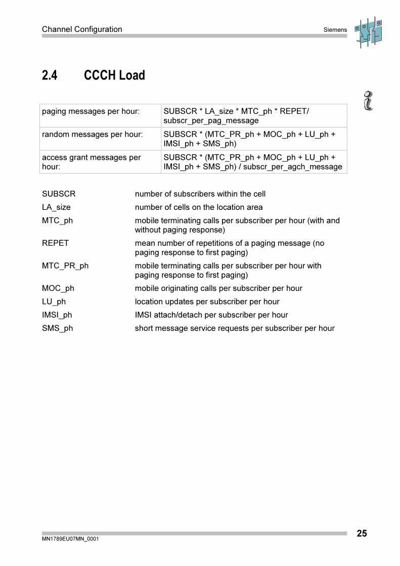
paging messages per hour: SUBSCR * LA_size * MTC_ph * REPET/subscr_per_pag_message
random messages per hour: SUBSCR * (MTC_PR_ph + MOC_ph + LU_ph +IMSI_ph + SMS_ph)
access grant messages perhour:
SUBSCR * (MTC_PR_ph + MOC_ph + LU_ph +IMSI_ph + SMS_ph) / subscr_per_agch_message
SUBSCR number of subscribers within the cell
LA_size number of cells on the location area
MTC_ph mobile terminating calls per subscriber per hour (with andwithout paging response)
REPET mean number of repetitions of a paging message (nopaging response to first paging)
MTC_PR_ph mobile terminating calls per subscriber per hour withpaging response to first paging)
MOC_ph mobile originating calls per subscriber per hour
LU_ph location updates per subscriber per hour
IMSI_ph IMSI attach/detach per subscriber per hour
SMS_ph short message service requests per subscriber per hour

Siemens Channel Configuration
MN1789EU07MN_000126
CCCH Load (Example)
paging messages per hour: SUBSCR * LA_size * MTC_ph * REPET/subscr_per_pag_message
access grant messages perhour:
SUBSCR * (MTC_PR_ph + MOC_ph + LU_ph +IMSI_ph + SMS_ph) / subscr_per_agch_message
random messages per hour: SUBSCR * (MTC_PR_ph + MOC_ph + LU_ph +IMSI_ph + SMS_ph)
SUBSCR: ?
LA_size: 20
MTC_ph: 0.46
REPET: 1.33
MTC_PR_ph 0.30
MOC_ph 0.64
LU_ph 2.2
IMSI_ph 1.0
SMS_ph -
subscr_per_pag_message = 2
subscr_per_agch_message = 1.0
� paging messages per hour = SUBSCR * 20 * 0.46 * 1.33/2 � SUBSCR * 6/h
� access grant messages per hour � SUBSCR * 4/h
� paging + access grant messages per hour � SUBSCR * 10/h
� � 4600 subscriber (combined CCCH)
� � 14000 subscriber (uncombined CCCH)
� random access messages per hour � SUBSCR * 4 / h(at 10 % load)
� � 10000 subscriber (combined CCCH)
� � 20000 subscriber (uncombined CCCH)
Channel Configuration Siemens
MN1789EU07MN_000127
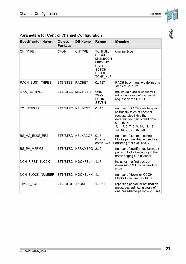
Parameters for Control Channel Configuration
Specification Name Object/Package
DB Name Range Meaning
CH_TYPE CHAN CHTYPE TCHFULLSDCCHMAINBCCHMBCCHCCCCHSCBCHBCBCHTCHF_HLF
channel type
RACH_BUSY_THRES BTS/BTSB RACHBT 0...127 RACH busy threshold defined insteps of -1 dBm
MAX_RETRANS BTS/BTSC MAXRETR ONETWOFOURSEVEN
maximum number of allowedretransmissions of a channelrequest on the RACH
TX_INTEGER BTS/BTSC NSLOTST 0...15 number of RACH slots to spreadre-transmission of channelrequest; also fixing thedeterministic part of wait time0 ... 15 �3, 4, 5, 6, 7, 8, 9, 10, 11, 12,14, 16, 20, 25, 32, 50
BS_AG_BLKS_RES BTS/BTSC NBLKACGR 0...70...2 forcomb. CCCH
number of common controlblocks per multiframe used foraccess grant exclusively
BS_PA_MFRMS BTS/BTSC NFRAMEPG 2...9 number of multiframes betweenpaging blocks belonging to thesame paging sub-channel
NCH_FIRST_BLOCK BTS/BTSC NOCHFBLK 1...7 indicates the first block ofdownlink CCCH to be used forNCH
NCH_BLOCK_NUMBER BTS/BTSC NOCHBLKN 1...4 number of downlink CCCHblocks to be used for NCH
TIMER_NCH BTS/BTST TNOCH 1...254 repetition period for notificationmessages defined in steps ofone multi-frame period – 235 ms

Siemens Channel Configuration
MN1789EU07MN_000128

Channel Configuration Siemens
MN1789EU07MN_000129
3 Extended Channel Mode
Siemens Channel Configuration
MN1789EU07MN_000130
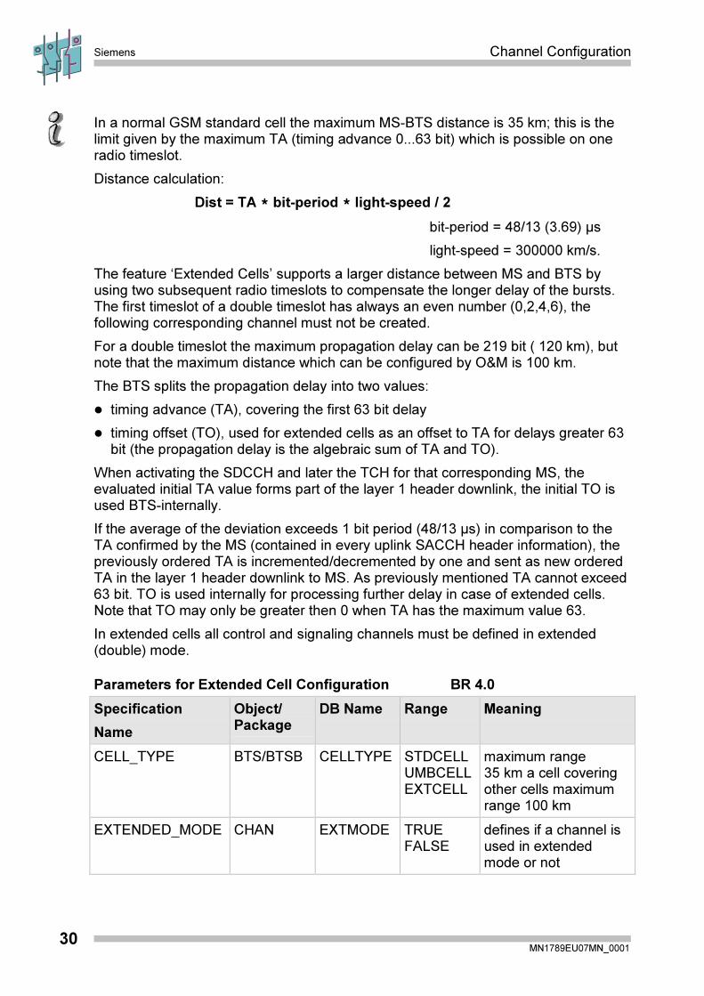
In a normal GSM standard cell the maximum MS-BTS distance is 35 km; this is thelimit given by the maximum TA (timing advance 0...63 bit) which is possible on oneradio timeslot.
Distance calculation:
Dist = TA * bit-period * light-speed / 2
bit-period = 48/13 (3.69) µs
light-speed = 300000 km/s.
The feature ‘Extended Cells’ supports a larger distance between MS and BTS byusing two subsequent radio timeslots to compensate the longer delay of the bursts.The first timeslot of a double timeslot has always an even number (0,2,4,6), thefollowing corresponding channel must not be created.
For a double timeslot the maximum propagation delay can be 219 bit ( 120 km), butnote that the maximum distance which can be configured by O&M is 100 km.
The BTS splits the propagation delay into two values:
� timing advance (TA), covering the first 63 bit delay
� timing offset (TO), used for extended cells as an offset to TA for delays greater 63bit (the propagation delay is the algebraic sum of TA and TO).
When activating the SDCCH and later the TCH for that corresponding MS, theevaluated initial TA value forms part of the layer 1 header downlink, the initial TO isused BTS-internally.
If the average of the deviation exceeds 1 bit period (48/13 µs) in comparison to theTA confirmed by the MS (contained in every uplink SACCH header information), thepreviously ordered TA is incremented/decremented by one and sent as new orderedTA in the layer 1 header downlink to MS. As previously mentioned TA cannot exceed63 bit. TO is used internally for processing further delay in case of extended cells.Note that TO may only be greater then 0 when TA has the maximum value 63.
In extended cells all control and signaling channels must be defined in extended(double) mode.
Parameters for Extended Cell Configuration BR 4.0
Specification
Name
Object/Package
DB Name Range Meaning
CELL_TYPE BTS/BTSB CELLTYPE STDCELLUMBCELLEXTCELL
maximum range35 km a cell coveringother cells maximumrange 100 km
EXTENDED_MODE CHAN EXTMODE TRUEFALSE
defines if a channel isused in extendedmode or not
Channel Configuration Siemens
MN1789EU07MN_000131
4 Exercise
Siemens Channel Configuration
MN1789EU07MN_000132
Channel Configuration Siemens
MN1789EU07MN_000133
Exercise 1
Title: Creation of RFC in SBS
Task
The object in SBS configuration language specifying a RFC is called TRX (trans-ceiver).
Take the UMN: BSC-CML (command list) for checking the input parameter required.

Siemens Channel Configuration
MN1789EU07MN_000134

Channel Configuration Siemens
MN1789EU07MN_000135
5 Solution

Siemens Channel Configuration
MN1789EU07MN_000136
Channel Configuration Siemens
MN1789EU07MN_000137
Solution
Title: Creation of RFC in SBS
Objectives:
Pre-requisite:
Task
CREATE TRX:NAME=BSC:0/bts:0/trx:0, TRXFREQ=75, PWRRED=0, RADIOMR=OFF,
RADIOMG=254, MOEC=TRUE, TRXAREA=NONE;
The parameters are specified as following:
BSC: BSC number to the related OMC 0 ... 47
bts: BTS/CELL number to the related BSC 0 ... 119
trx: TRX number to the related cell 0 ... 6
TRXFREQ: TRX-frequency - ARFCN 0 ... 1023
PWRRED: Power reduction [0...12 dB in steps of 2 dB] fordecrease max. transmit power
0 ... 6
RADIOMR: Radio measurement reports from TRXto the BSC ON/OFF
RADIOMG: Granularity of radio measurement reports insteps of 1 SACCH multiframe
0 ... 254
MOEC Member of emergency configuration TRUE/FALSE
TRXAREA: Configuration of concentric cells NONE/COMPLETE/INNER

Siemens Channel Configuration
MN1789EU07MN_000138