channel estimation for orthogonal time frequency space...
TRANSCRIPT
4204 IEEE TRANSACTIONS ON SIGNAL PROCESSING, VOL. 67, NO. 16, AUGUST 15, 2019
Channel Estimation for Orthogonal Time FrequencySpace (OTFS) Massive MIMO
Wenqian Shen , Member, IEEE, Linglong Dai , Senior Member, IEEE, Jianping An , Member, IEEE,Pingzhi Fan, Fellow, IEEE, and Robert W. Heath, Jr. , Fellow, IEEE
Abstract—Orthogonal time frequency space (OTFS) modulationoutperforms orthogonal frequency division multiplexing (OFDM)in high-mobility scenarios. One challenge for OTFS massive MIMOis downlink channel estimation due to the large number of base sta-tion antennas. In this paper, we propose a 3D-structured orthogonalmatching pursuit algorithm based channel estimation technique tosolve this problem. First, we show that the OTFS MIMO channelexhibits 3D-structured sparsity: normal sparsity along the delaydimension, block sparsity along the Doppler dimension, and burstsparsity along the angle dimension. Based on the 3D-structuredchannel sparsity, we then formulate the downlink channel estima-tion problem as a sparse signal recovery problem. Simulation re-sults show that the proposed algorithm can achieve accurate chan-nel state information with low pilot overhead.
Index Terms—OTFS, massive MIMO, channel estimation, high-mobility, sparsity.
I. INTRODUCTION
ONE goal of future wireless communications (the emerging5G or beyond 5G) is to support reliable communications
in high-mobility scenarios, such as on high-speed railways witha speed of up to 500 km/h [1], [2] or on vehicles with a speedof up to 300 km/h [3], [4]. Currently, the dominant modulationtechnique for 4G and the emerging 5G is orthogonal frequencydivision multiplexing (OFDM). For the high-mobility scenar-ios, OFDM may experience significant inter-carrier interference
Manuscript received October 15, 2018; revised March 17, 2019; acceptedMay 7, 2019. Date of publication May 31, 2019; date of current version July18, 2019. The associate editor coordinating the review of this manuscript andapproving it for publication was Dr. Bruno Clerckx. This work was supportedin part by the National Science Foundation under Grants NSF-CCF-1514275,ECCS-1711702, and CNS-1731658, and in part by the National Natural ScienceFoundation of China (NSFC) under Grant 61620106001, in part by the NSFC-NRF Project under Grant 61661146003, in part by the NSFC for OutstandingYoung Scholars under Grant 61722109, in part by the National Science andTechnology Major Project of China under Grant 2018ZX03001004-003, and inpart by the 111 Project under Grant 111-2-14. R. W. Heath, Jr., is also on theTechnical Advisory Board of Cohere Technologies, which developed OTFS. Theterms of this arrangement have been reviewed and approved by the Universityof Texas at Austin in accordance with its policy on objectivity in research.(Corresponding author: Jianping An.)
W. Shen and J. An are with the School of Information and Electronics, Bei-jing Institute of Technology, Beijing 100081, China (e-mail: [email protected];[email protected]).
L. Dai is with the Department of Electronic Engineering, Tsinghua University,Beijing 100084, China (e-mail: [email protected]).
P. Fan is with the Institute of Mobile Communications, Southwest JiaotongUniversity, Chengdu 610031, China (e-mail: [email protected]).
R.W. Heath, Jr. is with the Department of Electrical and Computer Engineer-ing, the University of Texas at Austin, Austin, TX 78712-1687 USA (e-mail:[email protected]).
Digital Object Identifier 10.1109/TSP.2019.2919411
(ICI) due to the Doppler spread of time-variant channels (whichare also referred to as doubly selective or doubly dispersivechannels). ICI will severely degrade the performance of OFDMsystems when the traditional transceivers are used [5].
To cope with ICI, some modifications of the traditional OFDMwere proposed at the cost of more complicated transceiver de-sign. Linear equalization [6]–[9] and non-linear equalization[10]–[12] were proposed to eliminate the ICI at the receiver.Some transmitter processing methods to mitigate ICI were pro-posed including polynomial cancellation coding [13], [14] andpulse shaping [15], [16]. Using both transmitter and receiver pro-cessing, a channel-independent block spreading based multipleaccess scheme was proposed for the multi-user scenarios, whereboth ICI and multiuser interference can be eliminated [17].
Instead of trying to eliminate ICI, there are some modulationschemes proposed for time-variant channels to enhance the sys-tem performance by using the transmit diversity. A frequency-oversampling technique for zero-padded OFDM system wasproposed in [18], where frequency diversity can be achievedthrough transmit signal design. Vector OFDM [19] transmitsmultiple groups of linearly precoded symbols over the channelsubcarriers to provide frequency diversity. A Doppler-resilientorthogonal signal division multiplexing technique was pro-posed. That multiplexes several data vectors and a pilot vectorinto a data stream to fully exploit the frequency-time diversityin the time-variant channels [20], [21].
Orthogonal time frequency space (OTFS) is an alternativeto OFDM to tackle the time-variant channels [22]–[24]. Lever-aging the basis expansion model (BEM) for the channel [25],[26], OTFS converts the time-variant channels into the time-independent channels in the delay-Doppler domain. Accord-ingly, the information bearing data is multiplexed into theroughly constant channels in the delay-Doppler domain. OTFSis different from previous work in that it multiplexes data in thedelay-Doppler domain.
Like OFDM multi-antenna systems, OTFS with massivemultiple-input multiple-output (MIMO) can further increasethe spectrum efficiency. Such benefits require that the channelstate information (CSI) is known at the transmitter to designthe transmit beamforming vectors [27]–[29]. When OTFS mas-sive MIMO systems are operated with frequency division duplex(FDD) mode, downlink channel estimation is necessary due tothe lack of channel reciprocity. With a large number of anten-nas equipped at the base station (BS) in OTFS massive MIMOsystems, downlink channel estimation is challenging.
1053-587X © 2019 IEEE. Personal use is permitted, but republication/redistribution requires IEEE permission.See http://www.ieee.org/publications_standards/publications/rights/index.html for more information.

SHEN et al.: CHANNEL ESTIMATION FOR ORTHOGONAL TIME FREQUENCY SPACE (OTFS) MASSIVE MIMO 4205
The time-variant channel estimation schemes for massiveMIMO systems have been proposed in [30]–[33]. In [30], thetime-variant MIMO channels are modeled by several jointlysparse time-independent coefficients based on the BEM. Thesejointly sparse coefficients can be estimated through a distributedcompressive sensing algorithm with high accuracy. In [31],a spatial-domain BEM was developed to further reduce theeffective dimensions of massive MIMO time-variant channels,such that the downlink training overhead can be reduced. More-over, a general framework of compressed channel sensing wasprovided in [32]. Based on the sparse multipath structure of mas-sive MIMO time-variant channels, compressed channel sensingcan achieve a target estimation error using much less overhead.To reduce the computational complexity for channel estimation,the Heisenberg-Weil flag sequences are designed in [33], whichenables a flag method for the Doppler-delay channel estimationwith reduced complexity. The aforementioned channel estima-tion techniques [30]–[33] were proposed for OFDM massiveMIMO systems. They are not directly applicable for OTFS mas-sive MIMO systems. This is because that the information bear-ing data is multiplexed in the delay-Doppler domain in OTFSsystems, not the frequency-time domain as in OFDM systems.
For OTFS systems, an impulse based channel estimation tech-nique was proposed for the OTFS single-input single-output(SISO) architecture in [34], [35]. The BS transmits an impulsein the delay-Doppler domain as the training pilots. The receivedsignals in the delay-Doppler domain can be regarded as a two-dimensional periodic convolution of the transmit impulse withthe delay-Doppler channel [34]. The delay-Doppler channel canthen be estimated from the received signal using a thresholdmethod [36]. An alternative method using pseudo-random noise(PN) sequences as the training pilots in the delay-Doppler do-main was proposed for OTFS SISO systems [37]. In that method,channel estimation is done in the discrete domain, where threequantities of interest, namely, delay shift, Doppler shift, and fadecoefficient are estimated. Then the delay-Doppler channel can becalculated accordingly. The impulse-based scheme is extendedto OTFS MIMO systems by transmitting several impulses withproper guard between two adjacent impulses to distinguish dif-ferent BS antennas [36], [38]. The existing channel estimationtechniques can not be directly extended to OTFS massive MIMOsince a large number of antennas are required to be distinguishedby transmitting orthogonal pilots, which will lead to high pilotoverhead.
To solve this problem, we propose a 3D structured orthog-onal matching pursuit (3D-SOMP) algorithm based downlinkchannel estimation technique for OTFS massive MIMO sys-tems, which can achieve accurate CSI with low pilot overhead.1
The specific contributions are summarized as follows.� We present the discrete-time formulation of OTFS sys-
tems and demonstrate that the OTFS massive MIMO chan-nel exhibits a delay-Doppler-angle 3D structured sparsity.Since the number of dominant propagation paths is lim-ited, the 3D channel is sparse along the delay dimension.As the Doppler frequency of a path is usually much smaller
1Simulation codes are provided to reproduce the results presented in thispaper: http://oa.ee.tsinghua.edu.cn/dailinglong/publications/publications.html.
than the system bandwidth, the 3D channel is block-sparsealong the Doppler dimension. The only one non-zero blockis concentrated around zero, but the length of the non-zero block is unknown. Since the angle-of-departure (AoD)spread of a path at the BS is usually small, the 3D channelis burst-sparse along the angle dimension [39]. The lengthsof non-zero bursts can be regarded as constant, but the startposition of each non-zero burst is unknown.
� Based on the 3D structured sparse channel, we formulatethe downlink channel estimation problem in OTFS massiveMIMO systems as a sparse signal recovery problem. Theestimator makes use of the training pilots that are transmit-ted in the delay-Doppler domain. We propose that pilotsof different antennas are independent complex Gaussianrandom sequences, which overlap to reduce the overall pi-lot overhead. By inserting guard intervals between pilotsand data, the received pilots can be expressed as a phasecompensated two-dimensional periodic convolution of thetransmit pilots with the delay-Doppler channel. Decom-posing the channel based on its structure, we formulate thedownlink channel estimation problem as a sparse signalrecovery problem.
� We propose a 3D-SOMP algorithm to solve the formulatedchannel estimation problem. The main idea is summarizedas follows. The 3D supports of each path is estimated ina one-by-one fashion. For each path, the user first esti-mates the delay-dimension supports. Then, by using theblock-sparse property of channels along the Doppler di-mension, the user estimates the size of the unique non-zeroblock to obtain the Doppler-dimension supports. Finally,the user transforms the burst-sparsity of channels along theangle dimension into the traditional block-sparsity througha lifting transformation following [39], so that the angle-dimension supports can be estimated accordingly. In thisway, the whole 3D channel can be estimated after severaliterations by removing the contribution of previous pathsin each iteration.
The rest of the paper is organized as follows. In SectionII, we present the system model. In Section III, we reviewthe channel estimation in OTFS SISO systems. Then, we pro-pose a 3D-SOMP based channel estimation technique for OTFSmassive MIMO systems in Section IV. Simulation results aregiven in Section V. Our conclusions are finally drawn inSection VI.
Notation: Boldface capital letters stand for matrices andlower-case letters stand for column vectors. The transpose,conjugate, conjugate transpose, and inverse of a matrix aredenoted by (·)T, (·)∗, (·)H and (·)−1, respectively. � is theHadamard product operator. ‖s‖ is the �2-norm of the vectors. Ψ† = (ΨHΨ)−1ΨH is the Moore-Penrose pseudo-inverse ofΨ. The operators vec{} and invec{} denote the vectorizing ofa matrix and invectorizing of a vector, respectively. Finally, INdenotes the identity matrix of size N ×N .
II. SYSTEM MODEL
In this section, we review OTFS for SISO systems includ-ing a discrete-time formulation of OTFS modulation and OTFS
4206 IEEE TRANSACTIONS ON SIGNAL PROCESSING, VOL. 67, NO. 16, AUGUST 15, 2019
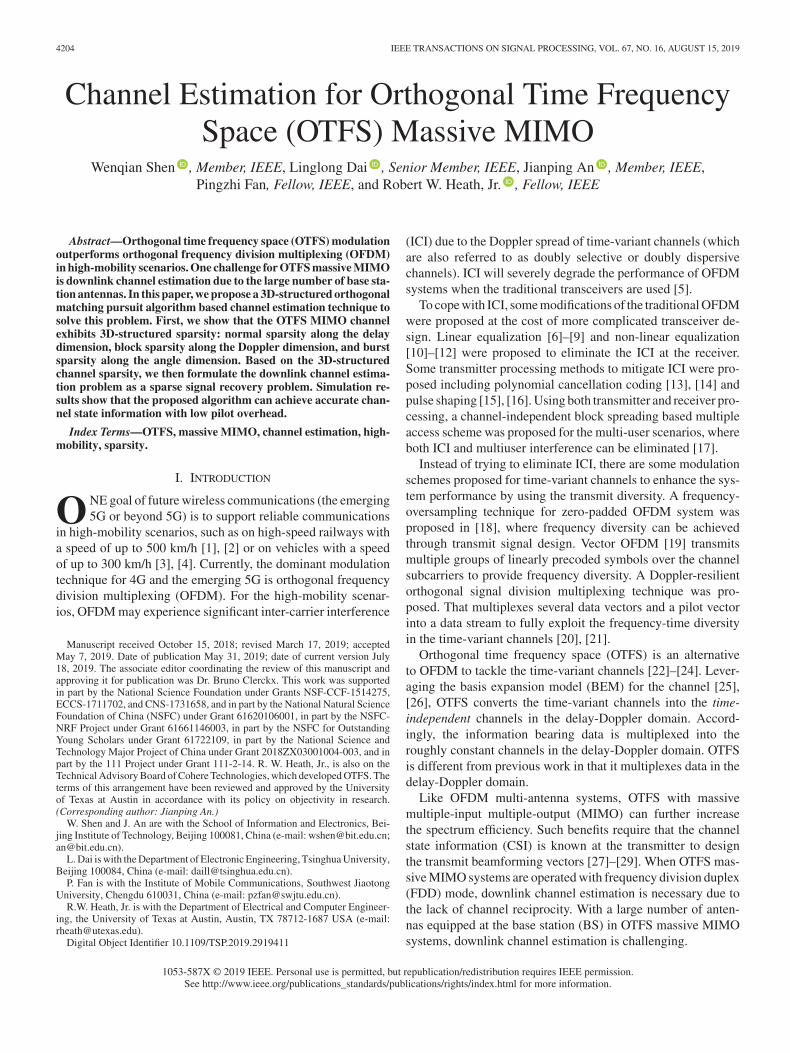
Fig. 1. OTFS SISO architecture. OTFS modulation is composed of a pre-processing block before a traditional OFDM modulator at the transmitter. OTFSdemodulation is composed of a post-processing block after a traditional OFDM demodulator at the receiver.
demodulation. Then, we describe an extension of OTFS intomassive MIMO systems.
Fig. 1 shows the OTFS SISO architecture as commonly as-sumed in [22]–[24]. OTFS is a modulation/demodulation tech-nique. It can be realized by adding a pre-processing block be-fore a traditional modulator in the frequency-time domain suchas OFDM modulator at the transmitter, and a correspondingpost-processing block after a traditional demodulator in thefrequency-time domain such as OFDM demodulator at the re-ceiver. Through the pre-processing and post-processing blocks,time-variant channels are converted into the time-independentchannels in the the delay-Doppler domain. Therefore, the in-formation bearing data can be multiplexed in the roughly con-stant delay-Doppler channel. At the same time, the transmit datain OTFS systems can take advantage of full diversity in thefrequency-time channels. In this way, OTFS improves systemperformance over OFDM in high-mobility scenarios [22]–[24].
A. OTFS SISO Modulation
In this section, we describe the modulation at the transmitter.A quadrature amplitude modulated (QAM) data sequence oflengthMN is first rearranged into a 2D data block. This is calleda 2D OTFS frame in the delay-Doppler domain XDD ∈ C
M×N ,where M and N are the numbers of resource units along thedelay dimension and Doppler dimension. OTFS modulation atthe transmitter is composed of a pre-processing block and atraditional frequency-time modulator such as OFDM or filterbank multicarrier (FBMC). The pre-processing block maps the2D data block XDD in the delay-Doppler domain to a 2D blockXFT ∈ C
M×N in the frequency-time domain. It is realized byusing an inverse symplectic finite Fourier transform (ISFFT) anda transmit windowing function. The ISFFT of XDD is [22]
XISFFT = FMXDDFHN, (1)
where FM ∈ CM×M and FN ∈ C
N×N are discrete Fouriertransform (DFT) matrices. A transmit windowing matrixWtx ∈CM×N multiplies XISFFT element-wise to produce the 2D
block in the frequency-time domain XFT as
XFT = XISFFT �Wtx. (2)
There are several uses of the windowing matrix. For example,the windowing matrix can be designed to randomize the phasesof the transmitted symbols to eliminate the inter-cell interference[34]. In this paper, we assume a trivial window at the transmitterfor simple expression, i.e., Wtx is a matrix of all ones.
Then, the 2D block XFT in the frequency-time domain istransformed to the 1D transmit signal s through a traditionalfrequency-time modulator such as OFDM or FBMC. Assumingan OFDM modulator, the M -point inverse DFT (IDFT) is ap-plied on each column of XFT to obtain the 2D transmit signalblock S ∈ C
M×N , i.e.,
S = FHMXFT, (3)
where S = [s1, s2, . . . , sN ]. Each column vector si ∈ CM×1 of
S can be regarded as an OFDM symbol. Note that N OFDMsymbols {si}Ni=1 occupy the bandwidth MΔf and have the du-ration NT , where Δf and T are the subcarrier spacing andsymbol duration. By combining (1)–(3),
S = XDDFHN. (4)
To avoid inter-symbol interference between blocks, the OFDMmodulator usually adds cyclic prefix (CP) for each OFDM sym-bol si via a CP addition matrix ACP ∈ C
(M+NCP)×M [24] withNCP being the length of CP. By reading the 2D transmit signalblockS column-wise, the 1D transmit signal s ∈ C
(M+NCP)N×1
is
s = vec{ACPS}. (5)
B. OTFS SISO Demodulation
In this section, we describe demodulation at the receiver. Theκ-th element of the received signal r ∈ C
(M+NCP)N×1 after thetime-variant channel hκ,� with length L+ 1 is expressed as
rκ =
L∑
�=0
hκ,�sκ−� + vκ, (6)

SHEN et al.: CHANNEL ESTIMATION FOR ORTHOGONAL TIME FREQUENCY SPACE (OTFS) MASSIVE MIMO 4207
where vκ is the additive noise at the receiver. The OTFS demod-ulation at the receiver consists of a traditional frequency-timedemodulator such as the OFDM or FBMC demodulator and apost-processing block as shown in Fig. 1. The frequency-timedemodulator transforms the received signal r to a 2D block in thefrequency-time domain YFT ∈ C
M×N . Specifically, assumingan OFDM demodulator, the received signal r is first rearrangedas a matrix R of size (M +NCP)×N , i.e.,
R = invec{r}, (7)
where each column vector of R can be regarded as a receivedOFDM symbol including CP. Then, the OFDM demodulatorremoves the CP by multiplying R with a CP removal ma-trix RCP ∈ C
M×(M+NCP) [24] to obtain the OFDM symbolsRCPRwithout CPs. Applying theM -point DFT on each OFDMsymbol without CP (i.e., each column vector of RCPR), we ob-tain the received 2D blockYFT in the frequency-time domain as
YFT = FMRCPR. (8)
In the post-processing block, YFT is transformed to the 2Ddata block YDD ∈ C
M×N in the delay-Doppler domain. It isrealized by a receive windowing matrix Wrx ∈ C
M×N andthe SFFT. The receive windowing matrix Wrx multiplies YFT
element-wise, i.e.,
YFT,W = YFT �Wrx. (9)
Then, the SFFT is applied for YFT,W to obtain the 2D datablock YDD in the delay-Doppler domain as
YDD = FHMYFT,WFN. (10)
Like the transmitter, we consider a trivial window at the receiverfor simple expression, i.e., Wrx is a matrix of all ones [34]. Bycombing (8)–(10), we can obtain
YDD = RCPRFN. (11)
The received 2D data block YDD in the delay-Doppler do-main is given by the phase compensated two-dimensional pe-riodic convolution of the transmit 2D data block XDD in thedelay-Doppler domain with the delay-Doppler channel im-pulse response (CIR) HDD ∈ C
M×N as shown in the follow-ing Lemma 1. Note that the OTFS modulation/demodulationis formulated in the discrete-time domain by applying theOTFS pre-processing/post-processing on the OFDM modula-tor/demodulator (with CP). In this case, the bi-orthogonal prop-erty of transmit/receive waveform exactly holds along the timedimension but only approximately holds along the frequency di-mension. This is different from the cases with ideal waveform[34] and rectangular waveform [40].
Lemma 1: We denote the (�+ 1, k + 1 +N/2)-th elementof YDD and XDD as Y DD
�,k andXDD�,k , where � = 0, 1, . . . ,M −
1 and k = −N/2, . . . , 0, . . . , N/2− 1. Then Y DD�,k can be ex-
pressed as
Y DD�,k
N→∞=
M−1∑
�′=0
N/2−1∑
k′=−N/2XDD�′,k′H
DD�−�′,k−k′e
j2π�(k−k′)
N(M+NCP)
+ V DD�,k , (12)
where V DD�,k is the additive noise in the delay-Doppler do-
main.HDD�,k is the (�+ 1, k + 1 +N/2)-th element of the delay-
Doppler CIR HDD and
HDD�,k =
N∑
i=1
h(i−1)(M+NCP)+1,(�)M e−j2π(i−1) k
N , (13)
where (�)M is the remainder after division of � by M . Notethat HDD
�,k = HDD�+M,k+N , thus (12) can be regarded as periodic
convolution.Proof: See Appendix. �We observe from (12) that the transmit dataXDD
�′,k′ in the delay-Doppler domain experiences roughly constant channel HDD
�,k inthe delay-Doppler domain, since the delay-Doppler CIR HDD
is time-independent (HDD does not vary with the variable κ ofhκ,�). Moreover, since each transmit data XDD
�′,k′ in the delay-Doppler domain is expanded onto the whole frequency-time do-main as shown in (1) and (2), it can exploit the full diversity of thefrequency-time channel. As a result, OTFS has improved per-formance over the traditional OFDM especially in high-mobilityscenarios [22]–[24].
Equalization is required to eliminate the inter-symbol inter-ference, since each transmit data XDD
�′,k′ in (12) experiences notonly the delay-Doppler channel XDD
�′,k′HDD0,0 but also the inter-
symbol interference XDD�′,k′H
DD�−�′,k−k′ , ∀�′ = �, k′ = k. To elim-
inate such inter-symbol interference through equalization, thedelay-Doppler CIR HDD is required, which is obtained throughdownlink channel estimation.
C. OTFS Massive MIMO
We explain how OTFS works in massive MIMO systemsto further increase the spectrum efficiency by using multi-user MIMO in this section. Fig. 2 shows the OTFS massiveMIMO architecture. The BS is equipped with Nt antennas tosimultaneously serve U single-antenna users. Downlink pre-coding is performed to eliminate the inter-user interference.For example, the zero-forcing Tomlinson-Harashima precodingis adopted in [28]. To perform downlink precoding, downlinkCSI is required, which is obtained from uplink channel feed-back in FDD systems.2 After precoding, the transmit data blockXDD in the delay-Doppler domain will be modulated throughthe OTFS modulation and transmitted at Nt antennas. At theuser side, the received signal is first demodulated through theOTFS demodulation to obtain the received data block YDD
in the delay-Doppler domain. To cancel the inter-symbol inter-ference, equalization is performed based on the downlink CSI.Next, we will focus on the downlink channel estimation in OTFSSISO/massive MIMO systems.
2Note that the obtained delay-Doppler CIR HDD may be delayed dueto the signal processing time and feedback time. However, it still canbe used for downlink precoding, since the channel coherence time inOTFS systems is increased by orders of magnitude compared with OFDMsystems [34].

4208 IEEE TRANSACTIONS ON SIGNAL PROCESSING, VOL. 67, NO. 16, AUGUST 15, 2019
Fig. 2. OTFS massive MIMO architecture. Multi-user MIMO is used to increase the spectrum efficiency. Downlink precoding is performed based on the downlinkCSI [28], which is obtained through downlink channel estimation and uplink channel feedback in FDD systems.
III. CHANNEL ESTIMATION IN OTFS SISO SYSTEMS
The goal of channel estimation is to obtain the delay-DopplerCIR HDD from the received delay-Doppler data block YDD in(12). One intuitive method to estimate HDD is to transmit animpulse in the delay-Doppler domain as the training pilots [34].The transmit impulse is expressed as
XDD�,k =
{1, � = 0, k = 0,0, � = 0, k = 0.
(14)
Based on (12), the received signal in the delay-Doppler domaincan be expressed as
Y DD�,k = HDD
�,k ej2π �k
N(M+NCP) + V DD�,k , (15)
The delay-Doppler CIR HDD�,k can be estimated from Y DD
�,k in(15) through the least square (LS) estimator or minimum meansquare error (MMSE) estimator [38]. Note that only the non-zero part ofHDD
�,k need to be estimated due to its finite supports,which will be explained later.
This impulse based channel estimation technique, however,is not applicable to massive MIMO systems due to the hugerequired pilot overhead. In OTFS massive MIMO systems, todistinguish the delay-Doppler channels associated with Nt BSantennas at the user side, Nt impulses are required to be trans-mitted. We assume that the delay-Doppler CIRs HDD
�,k of Nt
antennas have finite supports [0 :Mmax − 1] along the delaydimension and
[−Nmax
2 : Nmax
2 − 1]
along the Doppler dimen-sion [22], [28], [34]. To avoid the interference among multipleantennas, guard intervals between two adjacent impulses shouldnot be smaller than Nmax along the Doppler dimension and nosmaller than Mmax along the delay dimension [34]. As a result,the length of pilots to transmit Nt impulses in OTFS massiveMIMO systems should be ∝ NtNmaxMmax. With a large num-ber of BS antennas, the pilot overhead will be overwhelming.To solve this problem, we propose a 3D-SOMP algorithm basedchannel estimation technique, which can obtain the accurate CSIwith considerably reduced pilot overhead.
IV. PROPOSED 3D-SOMP BASED CHANNEL ESTIMATION IN
OTFS MASSIVE MIMO SYSTEMS
In this section, we first demonstrate the 3D structured spar-sity of channels in OTFS massive MIMO systems. Then, weformulate the downlink channel estimation problem as a sparsesignal recovery problem. To solve this problem, we proposea 3D-SOMP algorithm. Finally, we analyze the required pilotoverhead for the proposed 3D-SOMP based channel estimationtechnique.
A. 3D Structured Sparsity of Delay-Doppler-angle Channel
We consider an OTFS massive MIMO system with Nt an-tennas at the BS and U single-antenna users. Downlink channelestimation is the same for U users. Therefore, we focus on acertain user and omit the subscript for the user without loss ofgenerality. We consider the downlink time-variant channel con-sisting of Np dominant propagation paths. Each dominant pathis composed of Ns subpaths. The si-th subpath in the i-th dom-inant path has a complex path gain αsi and Doppler frequencyνsi . The delays of all subpaths in the i-th dominant path canbe regarded as the same τi [41]. We denote the physical AoDof the si-th subpath as θsi . When a typical uniform linear array(ULA) of antennas is considered, the spatial angle associatedwith θsi is defined asψsi =
dλ sin θsi [42], where d is the antenna
spacing and λ is the wavelength of the carrier frequency. Typi-cally, d = λ/2 and θsi ∈ [−π/2, π/2), thus ψsi ∈ [−1/2, 1/2).The time-variant channel associated with the (p+ 1)-th antenna(p = 0, 1, . . . , Nt − 1) can be expressed as [43]
hκ,�,p =
Np∑
i=1
Ns∑
si=1
αsiej2πνsiκTsprc(�Ts − τi)e
−j2πpψsi , (16)
where prc(τ) is the band-limited pulse shaping filter responseevaluated at τ and Ts =
1MΔf is the system sampling inter-
val. Based on (13), we express the delay-Doppler CIR of the(p+ 1)-th antenna (which is referred to as delay-Doppler-space

SHEN et al.: CHANNEL ESTIMATION FOR ORTHOGONAL TIME FREQUENCY SPACE (OTFS) MASSIVE MIMO 4209
Fig. 3. Delay-Doppler-angle 3D channel, which is sparse along the delay di-mension, block-sparse along the Doppler dimension, and burst-sparse along theangle dimension.
CIR HDDS�,k,p in OTFS massive MIMO systems, where �, k and p
correspond to the delay, Doppler and spatial index) as follows
HDDS�,k,p =
N∑
n=1
h(n−1)(M+NCP)+1,(�)M ,pe−j2π(n−1) k
N
=
Np∑
i=1
Ns∑
si=1
βsiΥN (νsiNT − k) prc ((�)MTs − τi) e−j2πpψsi ,
(17)
where βsi = αsiej2πνsiTs , ΥN (x) �
∑Nn=1 e
j2π xN (n−1) =
sin(πx)sin(π x
N )ejπ
x(N−1)N and T = (M +NCP)Ts.
To investigate the 3D structured sparsity of channels in OTFSmassive MIMO systems, we define the delay-Doppler-anglechannel HDDA
�,k,r by applying inverse DFT for HDDS�,k,p along the
space-dimension p as
HDDA�,k,r
Δ=
Nt−1∑
p=0
HDDS�,k,pe
j2π rpNt (18)
where r = −Nt
2 , . . . , 0, . . . ,Nt
2 − 1 is the angle index. Then, bysubstituting (17) into (18), we can express the delay-Doppler-angle channel HDDA
�,k,r as
HDDA�,k,r =
Np∑
i=1
Ns∑
si=1
βsiΥN (νsiNT − k)
× prc ((�)MTs − τi)ΥNt(r − ψsiNt). (19)
We arrange HDDA�,k,r into a 3D tensor H ∈ C
M×N×Nt , whereHDDA�,k,r is the (�+ 1, k +N/2 + 1, r +Nt/2 + 1)-th element of
H (� = 0, 1, . . . ,M − 1, k = −N/2, . . . , 0, . . . , N/2− 1, andr = −Nt/2, . . . , 0, . . . , Nt/2− 1).
The function ΥN (x) has the following characteristic:|ΥN (x)| ≈ 0 when |x| 1 [44]. Therefore, HDDA
�,k,r has domi-nant elements only if k ≈ νsiNT , � ≈ τiMΔf , and r ≈ ψsiNt.As shown in Fig. 3, since the number of dominant paths issmall, e.g., Np = 6 [41] (the path delays of Ns subpaths of a
dominant path are regarded as the same [43]), the delay-Doppler-angle channel H is sparse along the delay dimension �. As-suming that the largest path delay is τmax, then H has finitesupports [0 :Mmax − 1] along the delay dimension �, whereMmax ≈ τmaxMΔf .
Additionally, the Doppler frequency of the si-th subpath inthe i-th dominant path can be expressed as νsi =
v
λsinφsi
[43], where v is the moving velocity of the user and φsi isthe angle between the user’s moving direction and the arriv-ing direction of the si-th subpath. Therefore, the maximumDoppler of a subpath is νmax
2 = vλ . Since φsi is distributed in
[−π/2, π/2), νsi is distributed in [− νmax
2 , νmax
2 ). Therefore,H has finite supports
[−Nmax
2 : Nmax
2 − 1]
along the Dopplerdimension k, where Nmax ≈ νmaxNT . For example, for thetypical subcarrier spacing Δf = 15 kHz and carrier frequency2.15 GHz, the maximum Doppler of a user with a speed of180 km/h equals to νmax
2 = 358 Hz. Thus, Nmax
2 ≈ νmax
2 NT ≈νmax
2 N/Δf ≈ 0.05N2 . There are only about 5% dominant ele-ments along the Doppler dimension. That is to say, the delay-Doppler-angle channel H is block-sparse along the Doppler di-mension k, where the unique non-zero block is centered aroundk = 0 but the length of the non-zero block is unknown.
Finally, for the angle dimension r, since the angle spreadof a dominant path is small, ψsi is distributed in Np pieces in[−1/2, 1/2). Therefore, the delay-Doppler-angle channel H isburst-parse [39] along the angle dimension r. There areNp non-zero blocks but the start position of each block is unknown, sincethe path may arrive from any directions. Note that the differencebetween the burst-sparsity and the traditional block-sparsity isthat, the start position of the non-zero burst is not necessarily tobe {1, 1 +D, 1 + 2D, · · · } where D is the length of non-zeroblocks.3
To sum up, we decompose the multipaths of time-variantchannels to show its structured sparsity along the delay di-mension, Doppler dimension, and angle dimension as shownin Fig. 3. The 3D channel tensor H is sparse along the delay di-mension, block-sparse along the Doppler dimension, and burst-sparse along the angle dimension. This 3D structured sparsitycan be used to estimate the CSI with low pilot overhead.
B. Formulation of Downlink Channel Estimation
Fig. 4 shows an OTFS frame of size M ×N in the delay-Doppler domain. The length of pilots along the Doppler dimen-sion and the delay dimension areNν andMτ . We propose to usecomplex Gaussian random sequences as the training pilots. Toavoid interference between pilots and data caused by the two-dimensional periodic convolution in the delay-Doppler domain,guard intervals are required. Note that the delay-Doppler-anglechannel H in OTFS massive MIMO systems has finite sup-ports
[−Nmax
2 : Nmax
2 − 1]
along the Doppler dimension and[0 :Mmax − 1] along the delay dimension. The length of guard
3Note that the assumption of a constant burst size D is restrictive for practice.This assumption could be relaxed by using the statical sparsity models [45]. Theproposed algorithm could be correspondingly extended to learn the variableburst size by using the expectation-maximization (EM) or Bayesian learningmethods [46] in our future work.

4210 IEEE TRANSACTIONS ON SIGNAL PROCESSING, VOL. 67, NO. 16, AUGUST 15, 2019
Fig. 4. An OTFS frame in the delay-Doppler domain with pilots and guardintervals.
intervals should be Ng
2 ≥ Nmax
2 − 1 along the Doppler dimen-sion andMg ≥Mmax − 1 along the delay dimension4 as shownin Fig. 4. To reduce the overall pilot overhead in OTFS massiveMIMO systems, we propose the non-orthogonal pilot pattern,i.e., the transmit pilots at different antennas are completely over-lapped in the delay-Doppler domain, but the complex Gaussianrandom sequences (pilots) at different antennas are independent.
The training pilots in the delay-Doppler domain at the (p+1)-th antenna are denoted as x�,k,p with � = 0, 1, . . . ,Mτ − 1,k = −Nν
2 , . . . , 0, . . . ,Nν
2 − 1, and p = 0, 1, . . . , Nt − 1. TheOTFS frames at Nt antennas will be modulated and transmittedsimultaneously. After passing the channel, the received signalis demodulated, and then the guard intervals are discarded. Ac-cording to (12), the received pilots in the delay-Doppler domainat the user side can be expressed as
y�,k =
Nt−1∑
p=0
Mg−1∑
�′=0
Ng2 −1∑
k′=−Ng2
w�−�′,k′HDDS�′,k′,px�−�′,k−k′,p + v�,k,
(20)
where w�−�′,k′ = ej2π
(�−�′)k′N(M+NCP) is the compensate phase, k =
−Nν
2 , . . . , 0, . . . ,Nν
2 − 1, � = 0, 1, . . . ,Mτ − 1. The delay-Doppler-space channel HDDS
�,k,p can be expressed as the DFT ofthe delay-Doppler-angle channel HDDA
�,k,r based on (18), i.e.,
HDDS�,k,p =
Nt2 −1∑
r=−Nt2
HDDA�,k,r e
−j2π rpNt . (21)
4Note that the parameters Nmax and Mmax should be carefully estimatedin practice. The uncertainty of parameter estimation will lead to interferencebetween pilot and data.
By substituting (21) into (20) and expressing z�−�′,k−k′,r =∑Nt−1p=0 e−j2π
rpNt x�−�′,k−k′,p, we have
y�,k =
Nt2 −1∑
r=−Nt2
Mg−1∑
�′=0
Ng2 −1∑
k′=−Ng2
w�−�′,k′HDDA�′,k′,rz�−�′,k−k′,r + v�,k.
(22)
To simplify the expression, we rewrite (22) into the vector-matrix form. We arrange y�,k (k = −Nν
2 , . . . , 0, . . . ,Nν
2 −1, � = 0, 1, . . . ,Mτ − 1) into column vectors y ∈ C
MτNν×1,where the (�Nν + k +Nν/2 + 1)-th elements of y equal toy�,k. We also arrangeHDDA
�′,k′,r (k′ = −Ng/2, . . . , 0, . . . , Ng/2−1, �′ = 0, 1, . . . ,Mg − 1) into column vector hr ∈ C
MgNg×1,where the (�′Ng + k′ +Ng/2 + 1)-th elements of hr equal toHDDA�′,k′,r. As a result, (22) can be rewritten in the vector-matrix
form as
y =
Nt2 −1∑
r=−Nt2
W � Zc,rhr + v, (23)
where Zc,r ∈ CMτNν×MgNg is the two-dimensional pe-
riodic convolution matrix with the (�Nν + k +Nν/2 +1, �′Ng + k′ +Ng/2 + 1)-th element of Zc,r being equal toz�−�′,k−k′,r, where k = −Nν
2 , . . . , 0, . . . ,Nν
2 − 1, � = 0, 1, . . . ,
Mτ − 1, k′ = −Ng
2 , . . . , 0, . . . ,Ng
2 − 1, and �′ = 0, 1, . . . ,Mg
− 1. W ∈ CMτNν×MgNg is a matrix with the (�Nν + k +Nν/
2 + 1, �′Ng + k′ +Ng/2 + 1)-th element being w�−�′,k′ . Bydenoting Zc,W = [W � Z
c,−Nt2, . . . ,W � Zc,0, . . . ,W �
Zc,
Nt2 −1
] ∈ CMτNν×MgNgNt and h = [hT
−Nt2
, . . . ,hT0 , . . . ,
hTNt2 −1
]T ∈ CMgNgNt × 1, (23) can be expressed as
y = Zc,Wh+ v. (24)
Note that h can be inversely vectorized to obtain a truncateddelay-Doppler-angle channel Hg ∈ C
Mg×Ng×Nt , i.e., Hg =invec{h}, which is composed of the non-zero part of H with� = 0, 1, . . . ,Mg − 1, k = −Ng
2 , . . . , 0, . . . ,Ng
2 − 1, and r =
−Nt
2 , . . . , 0, . . . ,Nt
2 − 1. In this way, we formulate the OTFSchannel estimation problem as a sparse signal recovery problemwith the sensing matrix Ψ = Zc,W
y = Ψh+ v. (25)
This problem can be solved by traditional CS algorithms suchas the OMP algorithm [47]. In the next subsection, we proposea 3D-SOMP algorithm to recover the channel vector h (or thetruncated 3D channel Hg) in (25) with improved performancecompared with the traditional OMP algorithm.
C. 3D-SOMP Algorithm
The proposed 3D-SOMP algorithm is presented inAlgorithm 1. We borrow the main idea of OMP to obtain thecorrelation vector e between the columns of sensing matrix Ψand the residual measurements r = y −Ψh(0) with h(0) = 0

SHEN et al.: CHANNEL ESTIMATION FOR ORTHOGONAL TIME FREQUENCY SPACE (OTFS) MASSIVE MIMO 4211
Algorithm 1: Proposed 3D-SOMP Algorithm.1: Input:
1) Measurements y; 2) Sensing matrix Ψ2: Initialization:
i = 0Ω = ∅h(i) = 0 % Initialize the channel vectorr = y −Ψh(i) % Initialize the residual measurements
3: for i ≤ Np do4: i = i+ 15: e = ΨHr6: E = invec{e}7: eτ (m) = ‖E(1)(m, :)‖8: m
(i)τ = argmaxmeτ (m) % Delay-dimension
supports9: eν(n) = ‖E(m(i)
τ , n, :)‖10: n
(i)ν = argminn
∥∥∥eν(Ng
2 − n :Ng
2 + n− 1)∥∥∥, s.t.
‖eν(Nt
2 − n : Nt
2 + n− 1) ‖≥ ε‖eν‖
11: Λ(i)ν =
{Ng
2 − n(i)ν , . . . ,
Ng
2 , . . . ,Ng
2 + n(i)ν − 1
}
% Doppler-dimension supports
12: eθ(r) =∥∥∥E
(m
(i)τ ,Λ
(i)ν , r
)∥∥∥13: dθ = LHeθ % Lifting transformation14: gθ(r) = ‖Dθ(r, :)‖15: ps = argmaxrgθ(r) % Start position of the
non-zero burst16: Λ
(i)θ = {ps, ps + 1, . . . , ps +D − 1}% Angle-dimension supports
17: Ω = Ω ∪ (m(i)τ ,Λ
(i)ν ,Λ
(i)θ ) % delay-Doppler-angle
3D supports18: h(i)|Ω = Ψ†
Ωy, h(i)|Ωc = 0 % Partial channelestimate
19: r = y −Ψh(i)
20: end for21: Output:
Recovered channel vector h = h(Np).
being the initial channel estimate
e = ΨHr. (26)
For the traditional OMP algorithm, the supports of the sparsechannel vector h can be identified by finding the columns of Ψthat is most correlated to the residual measurement r. Differentfrom OMP, to use the 3D structured sparsity of h (or Hg), werearrange the correlation vector e as a tensor E ∈ C
Mg×Ng×Nt
in step 6,
E = invec{e}. (27)
For the sake of presentation, we first introduce some nota-tions of aN -dimensional (N ≥ 3) tensor M ∈ C
I1×I2×,...,×IN .The mode-n fiber is obtained by fixing all indexes but the n-th index of M, i.e., M(i1, i2, . . . , in−1, :, in+1, . . . , iN ). Theslice is obtained by fixing all but two indexes of M, i.e.,M(i1, i2, . . . , in−1, :, :, in+2, . . . , iN ). Finally, the unfolding
operation transforms a N -dimensional tensor to a 2D matrix.The mode-n unfolding matrix M(n) ∈ C
In×I1I2···In−1In+1···INcan be obtained by arranging all the mode-nfibers as the columnsof M(n).
Our proposed 3D-SOMP algorithm identifies the 3D supportsof each dominant path in a one-by-one fashion. For each domi-nant path, the algorithm starts by obtaining the mode-1 unfold-ing matrix E(1) ∈ C
Mg×NgNt . By calculating the �2-norm ofrow vectors of E(1), the correlation vector eτ ∈ C
Mg×1 alongthe delay dimension is obtained with the m-th element
eτ (m) = ‖E(1)(m, :)‖. (28)
Thus, the delay-dimension indexm(i)τ of the i-th dominant path
can be obtain by finding the largest element of eτ , i.e., m(i)τ =
argmaxmeτ (m).Then, the user fixes the delay-dimension index m
(i)τ and
focuses on the slice E(m(i)τ , :, :) ∈ C
Ng×Nt to identify theDoppler- and angle-dimension supports. By calculating the �2-norm of row vectors of the slice E(m(i)
τ , :, :), the correlationvector eν ∈ C
Ng×1 along the Doppler dimension is obtainedwith the n-th element
eν(n) = ‖E(m(i)τ , n, :)‖. (29)
Since the truncated 3D channel Hg is block-sparse along theDoppler dimension and there is only one non-zero block centeredaround ν = 0, only the length of the non-zero block is unknown.It can be estimated by finding a smallest block in the Doppler-dimension correlation vector eν , where the ratio between theblock’s norm and ‖eν‖ should be larger than a threshold ε, i.e.,
n(i)ν = argminn
∥∥∥∥eν(Ng
2− n :
Ng
2+ n− 1
)∥∥∥∥ ,
s.t.
∥∥∥∥eν(Ng
2− n :
Ng
2+ n− 1
)∥∥∥∥ ≥ ε‖eν‖. (30)
Thus, the Doppler-dimension supports of the i-th dominant pathare obtained as Λ(i)
ν in step 11.Finally, we focus on E(Λ(i)
ν ,m(i)τ , :) to obtain the angle-
dimension supports of the i-th dominant path. Similarly, bycalculating the �2-norm of column vector of E(Λ(i)
ν ,m(i)τ , :),
the angle-dimension correlation vector eθ ∈ CNt×1 is obtained
with the r-th element
eθ(r) =∥∥∥E
(Λ(i)ν ,m(i)
τ , r)∥∥∥ . (31)
As we have discussed in the previous subsection, the truncated3D channel Hg is burst-sparse along the angle dimension. Thelength of the non-zero burst is assumed as D. The user needsto estimate the start position of the non-zero burst which is cor-related with the AoD of the i-th dominant path. The user firsttransforms the burst sparsity into the traditional block sparsitythrough a lifting transformation method following [39]. In thismethod, a burst-sparse vector of size Nt × 1 is connected to ablock-sparse vector with a higher diemnsionNtD × 1 via a lift-ing matrixL ∈ {0, 1}Nt×NtD. The start position of the non-zeroburst in the burst-sparse vector is correlated with the supports of

4212 IEEE TRANSACTIONS ON SIGNAL PROCESSING, VOL. 67, NO. 16, AUGUST 15, 2019
the non-zero block in the higher-dimensional block-sparse vec-tor. The ((i− 1)D + j)-th column of L (i = 1, 2, . . . , Nt andj = 1, 2, . . . , D) only has one non-zero element 1 at locationi⊕ j where
i⊕ j =
{i+ j, if i+ j ≤ Nt,
i+ j −Nt, if i+ j > Nt.(32)
To transform the burst sparsity of the truncated 3D channel Hg
along the angle dimension into the traditional block sparsity, theangle-dimension correlation vector eθ is modified by the liftingmatrix L as
dθ = LHeθ. (33)
Then dθ ∈ CNtD×1 is rearranged as a Nt ×D matrix Dθ. By
calculating the �2-norm of the row vectors of Dθ, we obtaingθ ∈ C
Nt×1 in step 14. Thus, the start position ps of the non-zeroburst is obtained by finding the largest element of gθ. Therefore,the angle-dimension supports correlated to the i-th dominantpath can be obtained as Λ
(i)θ = {ps, ps + 1, . . . , ps +D − 1}
in step 16.Up to this point, the delay-Doppler-angle 3D supports in
the i-th iteration can be obtained as Ω = Ω ∪ (m(i)τ ,Λ
(i)ν ,Λ
(i)θ ).
The user can partially estimate the channel through the LS ash(i)|Ω = Ψ†
Ωy, h(i)|Ωc = 0, where Ωc denotes the complemen-tary set of Ω. Then, the residual measurements is computed bysubtracting the contribution ofh(i) in the i-th iteration in step 19.After Np iterations, the complete channel estimate is obtainedas h = h(Np).
D. Performance Comparison
For the traditional impulse based channel estimation tech-nique (extended to OTFS massive MIMO systems), the pi-lot overhead is ∝ NtNmaxMmax. In our proposed channelestimation technique, the pilot overhead (i.e., the length ofmeasurements) is ∝ S log(L), where S and L are the spar-sity level and length of the sparse vector h, according to CStheory [48]. For our problem formulation in the last subsec-tion, S = NmaxNpD and L = NgMgNt. Therefore, the pi-lot overhead of our proposed channel estimation technique is∝ NmaxNpD log(NgMgNt).5 Note that the number of domi-nant paths is usually small, e.g., Np = 6 [41]. Since the anglespread of a dominant path is usually not large, the length ofnon-zero block along the angle dimension D is usually muchsmaller than the number of BS antennas Nt, e.g., D ≈ Nt/10[41]. The lengths of guard intervals Ng and Mg can be set asNmax and Mmax. Therefore, the pilot overhead of the proposed3D-SOMP based channel estimation is much lower than that ofthe previously proposed impulse based channel estimation.
V. SIMULATION RESULTS
In this section, we investigate the performance of the pro-posed 3D-SOMP based channel estimation technique, in terms
5Note that the order of required pilot overhead is larger than the number offree parameters of channelO(NsNp). Thus, there are space for better algorithmdesign to further reduce the order of pilot overhead.
TABLE ISYSTEM PARAMETERS FOR SIMULATION
of the normalized mean square error (NMSE) of channel esti-mation. The traditional impulse based channel estimation tech-nique is presented as a benchmark, where we use the LSestimator to estimate the delay-Doppler channel HDD
�,k (k =
−N2 , . . . , 0, . . . ,
N2 − 1 and � = 0, 1, . . . ,M − 1) of each an-
tenna from (15) as
HDD�,k =
⎧⎪⎪⎨
⎪⎪⎩
Y DD�,k e
−j2π �kN(M+NCP) ,
k ∈ [−Nmax
2 , Nmax
2 − 1]
� ∈ [0,Mmax − 1],
0,k /∈ [−Nmax
2 , Nmax
2 − 1]
� /∈ [0,Mmax − 1].
(34)
The NMSE of the traditional impulse based channel estimationtechnique is computed as
NMSE =
∑k=N2
k=−N2
∑�=M−1�=0 |HDD
�,k −HDD�,k |2
∑k=N2
k=−N2
∑�=M−1�=0 |HDD
�,k |2, (35)
which will be averaged overNt antennas. For the proposed chan-nel estimation technique, the channel vectorh in (25) can be esti-mated through the proposed 3D-SOMP algorithm as h. Then, his rearranged as aMg ×Ng ×Nt tensor Hg = invec{h}. Thus,the delay-Doppler-angle channel can be estimated as H|Γ = Hg
and H|Γc=0, where Γ is the index set of Hg. The NMSE of theproposed 3D-SOMP based channel estimation technique is com-puted as
NMSE =‖H − H‖2
‖H‖2 . (36)
We also present the NMSE of the traditional OMP based channelestimation technique for comparison when the traditional OMPalgorithm is used to recover h in (25).
We simulate the standardized spatial channel model in 3GPPconsidering the urban macro cell environment [49]. The detailedsystem parameters are summarized in Table I. Note that N forsimulations can not be set too large due to the limited compu-tational capability. The formulation error of channel estimation(25) due to a limited N is not obvious when N exceeds 10. Wedefine the pilot overhead ratio η as the ratio between the numberof resource units for pilot transmission and the number of to-tal resource units in the delay-Doppler domain. Given the total
SHEN et al.: CHANNEL ESTIMATION FOR ORTHOGONAL TIME FREQUENCY SPACE (OTFS) MASSIVE MIMO 4213
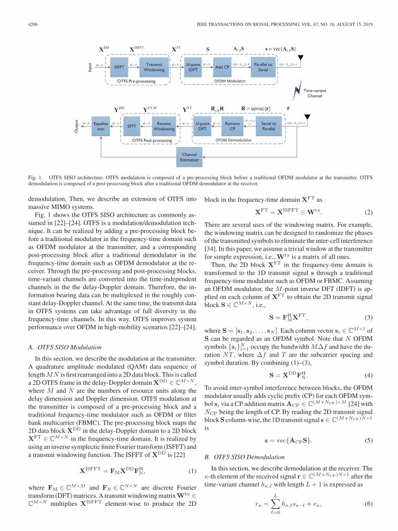
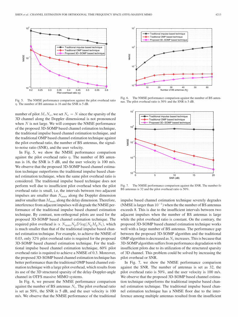
Fig. 5. The NMSE performance comparison against the pilot overhead ratioη. The number of BS antennas is 16 and the SNR is 5 dB.
number of pilotMτNν , we setNν = N since the sparsity of the3D channel along the Doppler dimensional is not pronouncedwhen N is not large. We will compare the NMSE performanceof the proposed 3D-SOMP based channel estimation technique,the traditional impulse based channel estimation technique, andthe traditional OMP based channel estimation technique againstthe pilot overhead ratio, the number of BS antennas, the signal-to-noise ratio (SNR), and the user velocity.
In Fig. 5, we show the NMSE performance comparisonagainst the pilot overhead ratio η. The number of BS anten-nas is 16, the SNR is 5 dB, and the user velocity is 100 m/s.We observe that the proposed 3D-SOMP based channel estima-tion technique outperforms the traditional impulse based chan-nel estimation technique, when the same pilot overhead ratio isconsidered. The traditional impulse based technique does notperform well due to insufficient pilot overhead when the pilotoverhead ratio is small, i.e, the intervals between two adjacentimpulses are smaller than Nmax along the Doppler dimensionand/or smaller thanMmax along the delay dimension. Therefore,interference from adjacent impulses will degrade the NMSE per-formance of the traditional impulse based channel estimationtechnique. By contrast, non-orthogonal pilots are used for theproposed 3D-SOMP based channel estimation technique. Therequired pilot overhead is ∝ NmaxNpD log(NgMgNt), whichis much smaller than that of the traditional impulse based chan-nel estimation technique. For example, to achieve the NMSE of0.03, only 32% pilot overhead ratio is required for the proposed3D-SOMP based channel estimation technique. For the tradi-tional impulse based channel estimation technique, 60% pilotoverhead ratio is required to achieve a NMSE of 0.3. Moreover,the proposed 3D-SOMP based channel estimation technique hasbetter performance than the traditional OMP based channel esti-mation technique with a large pilot overhead, which results fromits use of the 3D structured sparsity of the delay-Doppler-anglechannel in OTFS massive MIMO systems.
In Fig. 6, we present the NMSE performance comparisonagainst the number of BS antennas Nt. The pilot overhead ratiois set as 50%, the SNR is 5 dB, and the user velocity is 100m/s. We observe that the NMSE performance of the traditional
Fig. 6. The NMSE performance comparison against the number of BS anten-nas. The pilot overhead ratio is 50% and the SNR is 5 dB.
Fig. 7. The NMSE performance comparison against the SNR. The number foBS antennas is 32 and the pilot overhead ratio is 50%.
impulse based channel estimation technique severely degrades(NMSE is larger than 10−1) when the the number of BS antennasexceeds 8. This is due to the insufficient intervals between twoadjacent impulses when the number of BS antennas is largewhile the pilot overhead ratio is constant. On the contrary, theproposed 3D-SOMP based channel estimation technique workswell with a large number of BS antennas. The performance gapbetween the proposed 3D-SOMP algorithm and the traditionalOMP algorithm is decreased asNt increases. This is because that3D-SOMP algorithm suffers from performance degradation withinsufficient pilots due to its utilization of the structured sparsityof 3D channel. This problem could be solved by increasing thepilot overhead or SNR.
In Fig. 7, we show the NMSE performance comparisonagainst the SNR. The number of antennas is set as 32, thepilot overhead ratio is 50%, and the user velocity is 100 m/s.We observe that the proposed 3D-SOMP based channel estima-tion technique outperforms the traditional impulse based chan-nel estimation technique. The traditional impulse based chan-nel estimation technique has a NMSE floor due to the inter-ference among multiple antennas resulted from the insufficient

4214 IEEE TRANSACTIONS ON SIGNAL PROCESSING, VOL. 67, NO. 16, AUGUST 15, 2019
Fig. 8. The NMSE performance comparison against the user velocity. Thepilot overhead ratio is 50% and the SNR is 5 dB.
Fig. 9. The BER performance comparison against the SNR. The user velocityis set as 100 m/s.
pilot overhead. For the proposed 3D-SOMP based technique, theNMSE performance is improved with the increased SNR. More-over, the proposed 3D-SOMP based technique outperforms thetraditional OMP based technique by about 6 dB.
In Fig. 8, we show the NMSE performance comparisonagainst the user velocity v. The pilot overhead ratio is η = 50%,the SNR is 5 dB. We observe that the NMSE performance ofchannel estimation degrades as the user velocity increases. Thisis because that the Doppler spread νmax = v
λincreases with the
user velocity v, and the channel supports[−Nmax
2 : Nmax
2 − 1]
along the Doppler dimension is expanded. Thus, the requiredpilot overhead is increased to ensure a constant NMSE. With aconstant pilot overhead η = 50% in our simulation, the NMSEperformance of channel estimation degrades as the user velocityincreases.
Finally, in Fig. 9, we show the bit-error-rate (BER) compari-son against the SNR, where both OFDM and OTFS systems areconsidered. The user velocity is 100m/s. In this high-mobilitycase, the ICI caused by the large Dopppler spread degrades the
BER performance of OFDM systems, which is shown by thecurve “OFDM under ICI”. With the knowledge of perfect CSI,we use the MMSE detection to overcome the ICI shown as thecurve “OFDM with perfect CSI”, which outperforms the caseof “OFDM under ICI”. In the OTFS system, perfect CSI, theestimated CSI using the traditional impulse-based method, andthe estimated CSI using our proposed 3D-SOMP algorithm areindividually used for OTFS signal detection through the delay-Doppler 2D deconvolution. We observe that the OTFS systemoutperforms the OFDM system with the knowledge of perfectCSI in high SNR regime. This is because that the transmit datain OTFS systems can take advantages of full diversity in thefrequency-time channels. We also observe that the proposed3D-SOMP algorithm can achieve satisfying BER performance,which is very close to the case with perfect CSI in OTFS sys-tems. The traditional impulse-based channel estimation methodobtains inaccurate CSI, which leads to worse BER performance.
VI. CONCLUSIONS
In this paper, we studied the OTFS modulation for massiveMIMO systems for the first time with the focus on channel es-timation. Specifically, we transformed the time-variant massiveMIMO channels into the delay-Doppler-angle 3D channel inOTFS massive MIMO systems. We found that the 3D channel isstructured sparse, i.e., sparse along the delay dimension, block-sparse along the Doppler dimension, and burst-sparse along theangle dimension. Based on the 3D structured sparsity, we formu-lated the downlink channel estimation problem as a sparse signalrecovery problem and solved it with the proposed 3D-SOMP al-gorithm. Simulation results verified the superior performance ofour proposed technique. For future research, we will focus onsome open problems in OTFS massive MIMO systems such asthe low-complexity equalizer, downlink precoding, and efficientchannel feedback.
APPENDIX
PROOF OF LEMMA 1
Proof: Based on the OTFS modulation, each column vectorsi ∈ C
M×1 (i = 1, 2, . . . , N ) ofS is an OFDM symbol (withoutCP),
si = XDDf ∗i , (37)
where XDD is the 2D data block in the delay-Doppler do-main and fi ∈ C
N×1 is the i-th column vector of the DFTmatrix FN. Then, CP is added to each OFDM symbol andthese OFDM symbols with CPs are transmitted by the BS. Af-ter passing through the channel, the received OFDM symbolsare removed with CPs and arranged in the columns of matrixZ = [z1, z2, . . . , zN ] ∈ C
M×N ,
Z = RCPR. (38)
To avoid the inter-symbol interference, the length of CPNCP isusually larger than the channel length L, i.e., NCP > L. Thus,the i-th received OFDM symbol (without CP) zi ∈ C
M×1 isgiven by the circular convolution of the i-th transmit OFDM
SHEN et al.: CHANNEL ESTIMATION FOR ORTHOGONAL TIME FREQUENCY SPACE (OTFS) MASSIVE MIMO 4215
symbol (without CP) si with the time-variant channel, i.e.,
zi = Hcisi + vi, (39)
where Hci ∈ C
M×M is the circular convolution matrix, whose(a, b)-th element can be expressed as h(i−1)(M+NCP)+a,(a−b)M(a = 1, 2, . . . ,M and b = 1, 2, . . . ,M ), where (a− b)M is theremainder after division of a− b by M . vi is the additive noisevector. By substituting (37) into (39),
zi = HciX
DDf ∗i + vi. (40)
The received OFDM symbols Z without CPs are transformedto the 2D data block in the delay-Doppler domain YDD as (11),i.e.,
YDD = ZFN = [z1, z2, . . . , zN ]FN. (41)
We rewrite (41) as
YDD =
N∑
i=1
zifTi . (42)
By substituting (40) into (42),
YDD =
N∑
i=1
HciX
DDf ∗i fTi +VDD, (43)
where VDD = [v1,v2, . . . ,vN ]FN. We denote the (�+ 1, k +1 +N/2)-th element of YDD and XDD as Y DD
�,k and XDD�,k ,
where � = 0, 1, . . . ,M − 1 and k = −N/2, . . . , 0, . . . , N/2−1. Expanding to sum in (43), Y DD
�,k is given by
Y DD�,k =
M−1∑
�′=0
N/2−1∑
k′=−N/2XDD�′,k′
N∑
i=1
h(i−1)(M+NCP)+�+1,(�−�′)M
× e−j2π(i−1) k−k′N + V DD
�,k . (44)
We defineΛ�,(�−�′)M ,k−k′Δ=∑Ni=1h(i−1)(M+NCP)+�+1,(�−�′)M
e−j2π(i−1) k−k′N and focus on the calculation of Λl,(�−�′)M ,k−k′ .
We first expand the time-variant channels hκ,� based on theFourier series as
hκ,� =P∑
p=1
ωp,�ej2π
κfp,�N(M+NCP) , (45)
where P is the number of frequency component of time-variantchannels. fp,� is the p-th frequency component of the �-thchannel tap. ωp,� is the non-zero coefficient corresponding to
ej2π
κfp,�N(M+NCP) . Based on (45), Λ�,(�−�′)M ,k−k′ is expressed as
Λ�,(�−�′)M ,k−k′ =
N∑
i=1
P∑
p=1
ωp,(�−�′)M ej2π
((i−1)(M+NCP)+�+1)fp,(�−�′)MN(M+NCP) e−j2π(i−1) k−k′
N
=
P∑
p=1
ωp,(�−�′)M ej2π
(�+1)fp,(�−�′)MN(M+NCP)
N∑
i=1
ej2π(i−1)fp,(�−�′)M −(k−k′)
N .
(46)
We define a function ΥN (x) �∑Ni=1 e
j2π xN (i−1) = sin(πx)
sin(π xN )
ejπx(N−1)
N . Then, (46) is rewritten as
Λ�,(�−�′)M ,k−k′ =P∑
p=1
ωp,(�−�′)M ej2π
(�+1)fp,(�−�′)M
N(M+NCP)
×ΥN(fp,(�−�′)M − (k − k′)
). (47)
Now we can define the delay-Doppler CIRHDD�,k (k = −N/2,
. . . , 0, . . . , N/2− 1 and � = 0, 1, . . . ,M − 1) as
HDD�,k
Δ= Λ0,(�)M ,k
=
N∑
i=1
h(i−1)(M+NCP)+1,(�)M e−j2π(i−1) k
N . (48)
Then, HDD�−�′,k−k′ is given by
HDD�−�′,k−k′ = Λ0,(�−�′)M ,k−k′
=
P∑
p=1
ωp,(�−�′)MΥN(fp,(�−�′)M − (k − k′)
),
(49)
where ωp,(�−�′)M = ωp,(�−�′)M ej2π
fp,(�−�′)MN(M+NCP) . Now we will
prove that Λ�,(�−�′)M ,k−k′N→∞= e
j2π�(k−k′)
N(M+NCP)HDD�−�′,k−k′ .
Specifically, we first calculate
Λ�,(�−�′)M ,k−k′e−j2π �(k−k′)
N(M+NCP)
=P∑
p=1
ωp,(�−�′)M ej2π
�(fp,(�−�′)M −(k−k′))N(M+NCP)
ΥN(fp,(�−�′)M − (k − k′)
). (50)
It is noticed that the functionΥN (x) has the following character-istic: |ΥN (x)| → 0 when |x| 1 [44]. Thus we conclude thatthere are P dominant items in (50), which are obtained when∣∣fp,(�−�′)M − (k − k′)
∣∣ < 1. Since 0 ≤ � ≤M − 1, we have
ej2π
�(fp,(�−�′)M −(k−k′))N(M+NCP)
N→∞= 1. (51)
Therefore, by combining (49), (50), and (51),
Λ�,(�−�′)M ,k−k′N→∞= HDD
�−�′,k−k′ej2π
�(k−k′)N(M+NCP) . (52)
Finally, by substituting (52) into (44), we prove that
Y DD�,k
N→∞=
M−1∑
�′=0
N/2−1∑
k′=−N/2XDD�′,k′H
DD�−�′,k−k′e
j2π�(k−k′)
N(M+NCP)
+ V DD�,k . (53)
�
4216 IEEE TRANSACTIONS ON SIGNAL PROCESSING, VOL. 67, NO. 16, AUGUST 15, 2019
ACKNOWLEDGMENT
The terms of this arrangement have been reviewed and ap-proved by the University of Texas at Austin in accordance withits policy on objectivity in research.
REFERENCES
[1] B. Ai et al., “Challenges toward wireless communications for high-speedrailway,” IEEE Trans. Intell. Transp. Syst., vol. 15, no. 5, pp. 2143–2158,Oct. 2014.
[2] C. X. Wang, A. Ghazal, B. Ai, Y. Liu, and P. Fan, “Channel measurementsand models for high-speed train communication systems: A survey,” IEEECommun. Surveys Tut., vol. 18, no. 2, pp. 974–987, Apr.–Jun. 2016.
[3] J. Choi, V. Va, N. Gonzalez-Prelcic, R. Daniels, C. R. Bhat, and R. W.Heath, “Millimeter-wave vehicular communication to support massive au-tomotive sensing,” IEEE Commun. Mag., vol. 54, no. 12, pp. 160–167, Dec.2016.
[4] L. Dai, Z. Wang, and Z. Yang, “Time-frequency training OFDM with highspectral efficiency and reliable performance in high speed environments,”IEEE J. Sel. Areas Commun., vol. 30, no. 4, pp. 695–707, May 2012.
[5] H. Sari, G. Karam, and I. Jeanclaude, “Transmission techniques for digitalterrestrial TV broadcasting,” IEEE Commun. Mag., vol. 33, no. 2, pp. 100–109, Feb. 1995.
[6] W. G. Jeon, K. H. Chang, and Y. S. Cho, “An equalization techniquefor orthogonal frequency-division multiplexing systems in time-variantmultipath channels,” IEEE Trans. Commun., vol. 47, no. 1, pp. 27–32,Jan. 1999.
[7] X. Cai and G. B. Giannakis, “Bounding performance and suppressing in-tercarrier interference in wireless mobile OFDM,” IEEE Trans. Commun.,vol. 51, no. 12, pp. 2047–2056, Dec. 2003.
[8] P. Schniter, “Low-complexity equalization of OFDM in doubly selectivechannels,” IEEE Trans. Signal Process., vol. 52, no. 4, pp. 1002–1011,Apr. 2004.
[9] S. Das and P. Schniter, “Max-SINR ISI/ICI-shaping multicarrier commu-nication over the doubly dispersive channel,” IEEE Trans. Signal Process.,vol. 55, no. 12, pp. 5782–5795, Dec. 2007.
[10] Y.-S. Choi, P. J. Voltz, and F. A. Cassara, “On channel estimation anddetection for multicarrier signals in fast and selective Rayleigh fadingchannels,” IEEE Trans. Commun., vol. 49, no. 8, pp. 1375–1387, Aug.2001.
[11] A. F. Molisch, M. Toeltsch, and S. Vermani, “Iterative methods for can-cellation of intercarrier interference in OFDM systems,” IEEE Trans. Veh.Technol., vol. 56, no. 4, pp. 2158–2167, Jul. 2007.
[12] K. Fang, L. Rugini, and G. Leus, “Low-complexity block turbo equaliza-tion for OFDM systems in time-varying channels,” IEEE Trans. SignalProcess., vol. 56, no. 11, pp. 5555–5566, Nov. 2008.
[13] Y. Zhao and S. G. Haggman, “Intercarrier interference self-cancellationscheme for OFDM mobile communication systems,” IEEE Trans. Com-mun., vol. 49, no. 7, pp. 1185–1191, Jul. 2001.
[14] K. A. Seaton and J. Armstrong, “Polynomial cancellation coding and finitedifferences,” IEEE Trans. Inf. Theory, vol. 46, no. 1, pp. 311–313, Jan.2000.
[15] W. Kozek and A. F. Molisch, “Nonorthogonal pulseshapes for multicar-rier communications in doubly dispersive channels,” IEEE J. Sel. AreasCommun., vol. 16, no. 8, pp. 1579–1589, Oct. 1998.
[16] K. Liu, T. Kadous, and A. M. Sayeed, “Orthogonal time-frequency sig-naling over doubly dispersive channels,” IEEE Trans. Inf. Theory, vol. 50,no. 11, pp. 2583–2603, Nov. 2004.
[17] G. Leus, S. Zhou, and G. B. Giannakis, “Orthogonal multiple access overtime- and frequency-selective channels,” IEEE Trans. Inf. Theory, vol. 49,no. 8, pp. 1942–1950, Aug. 2003.
[18] Z. Wang, S. Zhou, G. B. Giannakis, C. R. Berger, and J. Huang,“Frequency-domain oversampling for zero-padded OFDM in underwateracoustic communications,” IEEE J. Ocean. Eng., vol. 37, no. 1, pp. 14–24,Jan. 2012.
[19] X.-G. Xia, “Precoded and vector OFDM robust to channel spectral nullsand with reduced cyclic prefix length in single transmit antenna systems,”IEEE Trans. Commun., vol. 49, no. 8, pp. 1363–1374, Aug. 2001.
[20] T. Ebihara and G. Leus, “Doppler-resilient orthogonal signal-division mul-tiplexing for underwater acoustic communication,” IEEE J. Ocean. Eng.,vol. 41, no. 2, pp. 408–427, Apr. 2016.
[21] T. Ebihara and K. Mizutani, “Underwater acoustic communication withan orthogonal signal division multiplexing scheme in doubly spread chan-nels,” IEEE J. Ocean. Eng., vol. 39, no. 1, pp. 47–58, Jan. 2014.
[22] R. Hadani et al., “Orthogonal time frequency space modulation,” in Proc.IEEE Wireless Commun. Netw. Conf., Mar. 2017, pp. 1–6.
[23] R. Hadani et al., “Orthogonal time frequency space (OTFS) modulationfor millimeter-wave communications systems,” in Proc. IEEE Int. Microw.Symp., Jun. 2017, pp. 681–683.
[24] A. Farhang, A. RezazadehReyhani, L. E. Doyle, and B. Farhang-Boroujeny, “Low complexity modem structure for OFDM-based orthogo-nal time frequency space modulation,” IEEE Wireless Commun. Lett., vol.7, no. 3, pp. 344–347, Jun. 2018.
[25] G. B. Giannakis and C. Tepedelenlioglu, “Basis expansion models and di-versity techniques for blind identification and equalization of time-varyingchannels,” Proc. IEEE, vol. 86, no. 10, pp. 1969–1986, Oct. 1998.
[26] P. Bello, “Characterization of randomly time-variant linear channels,”IEEE Trans. Commun., vol. 11, no. 4, pp. 360–393, Dec. 1963.
[27] R. Hadani et al., “Orthogonal time frequency space modulation,” 2018,arXiv:1808.00519.
[28] R. Hadani and A. Monk, “OTFS: A new generation of modulation address-ing the challenges of 5G,” 2018, arXiv:1802.02623.
[29] L. Li et al., “A simple two-stage equalizer with simplified orthogonaltime frequency space modulation over rapidly time-varying channels,”2017, arXiv:1709.02505.
[30] P. Cheng et al., “Channel estimation for OFDM systems over doublyselective channels: A distributed compressive sensing based approach,”IEEE Trans. Commun., vol. 61, no. 10, pp. 4173–4185, Oct. 2013.
[31] H. Xie, F. Gao, S. Zhang, and S. Jin, “A unified transmission strategy forTDD/FDD massive MIMO systems with spatial basis expansion model,”IEEE Trans. Veh. Technol., vol. 66, no. 4, pp. 3170–3184, Apr. 2017.
[32] W. U. Bajwa, J. Haupt, A. M. Sayeed, and R. Nowak, “Compressed channelsensing: A new approach to estimating sparse multipath channels,” Proc.IEEE, vol. 98, no. 6, pp. 1058–1076, Jun. 2010.
[33] A. Fish, S. Gurevich, R. Hadani, A. M. Sayeed, and O. Schwartz, “Delay-Doppler channel estimation in almost linear complexity,” IEEE Trans. Inf.Theory, vol. 59, no. 11, pp. 7632–7644, Nov. 2013.
[34] A. Monk, R. Hadani, M. Tsatsanis, and S. Rakib, “OTFS-orthogonal timefrequency space,” 2016, arXiv:1608.02993.
[35] R. Hadani and S. Rakib, “OTFS methods of data channel characterizationand uses thereof,” U.S. Patent 9 444 514 B2, Sep. 13, 2016.
[36] P. Raviteja, K. T. Phan, and Y. Hong, “Embedded pilot-aided channel esti-mation for OTFS in delay-Doppler channels,” IEEE Trans. Veh. Technol.,vol. 68, no. 5, pp. 4906–4917, May 2019.
[37] K. Murali and A. Chockalingam, “On OTFS modulation for high-dopplerfading channels,” in Proc. IEEE Inf. Theory Appl. Workshop, San Diego,CA, 2018, pp. 1–10.
[38] M. K. Ramachandran and A. Chockalingam, “MIMO-OTFS in high-doppler fading channels: Signal detection and channel estimation,” in Proc.IEEE Global Commun. Conf., Abu Dhabi, United Arab Emirates, 2018,pp. 206–212.
[39] A. Liu, V. K. N. Lau, and W. Dai, “Exploiting burst-sparsity in massiveMIMO with partial channel support information,” IEEE Trans. WirelessCommun., vol. 15, no. 11, pp. 7820–7830, Nov. 2016.
[40] P. Raviteja, K. T. Phan, Y. Hong, and E. Viterbo, “Interference cancellationand iterative detection for orthogonal time frequency space modulation,”IEEE Trans. Wireless Commun., vol. 17, no. 10, pp. 6501–6515, Oct. 2018.
[41] Spatial Channel Model for Multiple Input Multiple Output (MIMO) Sim-ulations, 3GPP TR 25.996 V12.0.0, Sep. 2014.
[42] R. W. Heath, N. Gonzalez-Prelcic, S. Rangan, W. Roh, and A. Sayeed,“An overview of signal processing techniques for millimeter wave MIMOsystems,” IEEE J. Sel. Topics Signal Process., vol. 10, no. 3, pp. 436–453,Apr. 2016.
[43] F. Hlawatsch and G. Matz, Wireless Communications Over Rapidly Time-varying Channels. New York, NY, USA: Academic, 2011.
[44] X. Gao, L. Dai, S. Han, C. L. I, and X. Wang, “Reliable beamspace channelestimation for millimeter-wave massive MIMO systems with lens antennaarray,” IEEE Trans. Wireless Commun., vol. 16, no. 9, pp. 6010–6021,Sep. 2017.
[45] L. Chen, A. Liu, and X. Yuan, “Structured turbo compressed sensing formassive MIMO channel estimation using a Markov prior,” IEEE Trans.Veh. Technol., vol. 67, no. 5, pp. 4635–4639, May 2018.
[46] A. Liu, L. Lian, V. K. N. Lau, and X. Yuan, “Downlink channel estimationin multiuser massive MIMO with hidden Markovian sparsity,” IEEE Trans.Signal Process., vol. 66, no. 18, pp. 4796–4810, Sep. 2018.

SHEN et al.: CHANNEL ESTIMATION FOR ORTHOGONAL TIME FREQUENCY SPACE (OTFS) MASSIVE MIMO 4217
[47] L. Dai, Z. Wang, and Z. Yang, “Spectrally efficient time-frequency train-ing OFDM for mobile large-scale MIMO systems,” IEEE J. Sel. AreasCommun., vol. 31, no. 2, pp. 251–263, Feb. 2013.
[48] D. L. Donoho, “Compressed sensing,” IEEE Trans. Inf. Theory, vol. 52,no. 4, pp. 1289–1306, Apr. 2006.
[49] J. Salo et al., “MATLAB implementation of the 3GPP SpatialChannel Model (3GPP TR 25.996),” Jan. 2005. [Online]. Available:http://www.tkk.fi/Units/Radio/scm/
Wenqian Shen (S’16–M’18) received the B.S. de-gree from Xi’an Jiaotong University, Xi’an, China, in2013 and the Ph.D. degree from Tsinghua University,Beijing, China. She is currently a Postdoctoral Re-search Fellow with the School of Information andElectronics, Beijing Institute of Technology, Bei-jing, China. Her research interests include massiveMIMO and mmWave/THz communications. She hasauthored or co-authored several journal and confer-ence papers in the IEEE TRANSACTION ON COM-MUNICATIONS, IEEE TRANSACTION ON VEHICULAR
TECHNOLOGY, IEEE ICC, etc. She has won the IEEE Best Paper Award at theIEEE ICC 2017.
Linglong Dai (M’11–SM’14) received the B.S. de-gree from Zhejiang University, Hangzhou, China, in2003, the M.S. degree (with the highest honor) fromthe China Academy of Telecommunications Technol-ogy, Beijng, China, in 2006, and the Ph.D. degree(with the highest honor) from Tsinghua University,Beijing, China, in 2011. From 2011 to 2013, he was aPostdoctoral Research Fellow with the Department ofElectronic Engineering, Tsinghua University, wherehe was an Assistant Professor from 2013 to 2016 andhas been an Associate Professor since 2016. He co-
authored the book MmWave Massive MIMO: A Paradigm for 5G (AcademicPress, Elsevier, 2016). He has authored or co-authored more than 60 IEEE jour-nal papers and more than 40 IEEE conference papers. He also holds 16 grantedpatents. His current research interests include massive MIMO, millimeter-wavecommunications, THz communications, NOMA, and machine learning for wire-less communications. He has received five IEEE Best Paper Awards at the IEEEICC 2013, the IEEE ICC 2014, the IEEE ICC 2017, the IEEE VTC 2017-Fall,and the IEEE ICC 2018. He has also received the Tsinghua University Outstand-ing Ph.D. Graduate Award in 2011, the Beijing Excellent Doctoral DissertationAward in 2012, the China National Excellent Doctoral Dissertation NominationAward in 2013, the URSI Young Scientist Award in 2014, the IEEE Transac-tions on Broadcasting Best Paper Award in 2015, the Electronics Letters BestPaper Award in 2016, the National Natural Science Foundation of China for Out-standing Young Scholars in 2017, the IEEE ComSoc Asia-Pacific OutstandingYoung Researcher Award in 2017, and the IEEE ComSoc Asia-Pacific Outstand-ing Paper Award in 2018. He is currently an Editor of the IEEE TRANSACTIONS
ON COMMUNICATIONS, the IEEE TRANSACTIONS ON VEHICULAR TECHNOLOGY,and the IEEE COMMUNICATIONS LETTERS. Particularly, he is dedicated to re-producible research and has made a large amount of simulation code publiclyavailable.
Jianping An (M’08) received the B.E. degree fromInformation Engineering University, Zhengzhou,China, in 1987, and the M.S. and Ph.D. degrees fromBeijing Institute of Technology, Beijing, China, in1992 and 1996, respectively. Since 1996, he has beenwith the School of Information and Electronics, Bei-jing Institute of Technology, where he is currently aFull Professor. From 2010 to 2011, he was a Visit-ing Professor with the University of California, SanDiego. He has authored or co-authored more than150 journal and conference articles and holds (or co-
holds) more than 50 patents. His current research interest is focused on digitalsignal processing theory and algorithms for communication systems. He hasreceived various awards for his academic achievements and the resultant indus-trial influences, including the National Award for Scientific and TechnologicalProgress of China (1997) and the Excellent Young Teacher Award by the China’sMinistry of Education (2000). Since 2010, he has been a Chief Reviewing Ex-pert for the Information Technology Division, National Scientific Foundation ofChina.
Pingzhi Fan (M’93–SM’99–F’15) received theM.Sc. degree in computer science from SouthwestJiaotong University, Chengdu, China, in 1987, andthe Ph.D. degree in electronic engineering from theHull University, Hull, U.K., in 1994. He is currently aDistinguished Professor and the Director of the Insti-tute of Mobile Communications, Southwest JiaotongUniversity, and a Visiting Professor with Leeds Uni-versity, Leeds, U.K. (1997 to present), a Guest Pro-fessor with Shanghai Jiaotong University (1999 topresent). He has authored or co-authored more than
290 international journal papers and 8 books (including edited), and is the in-ventor of 27 granted patents. His current research interests include vehicularcommunications, massive multiple access, and coding techniques, etc. He is arecipient of the UK ORS Award (1992), the NSFC Outstanding Young ScientistAward (1998), IEEE VTS Jack Neubauer Memorial Award (2018), and IEEESignal Processing Society Paper Award (2019). He was a General Chair or TPCChair of a number of international conferences including VTC’2016 Spring,IWSDA’2019, ITW’2018, etc. He is the Founding Chair of IEEE Chengdu (CD)Section, IEEE VTS BJ Chapter, and IEEE ComSoc CD Chapter. He was also anEXCOM member of IEEE Region 10, IET(IEE) Council, and IET Asia-PacificRegion. He is an IEEE VTS Distinguished Lecturer (2015–2019), and a Fellowof the IET, CIE, and CIC.
Robert W. Heath, Jr. (S’96–M’01–SM’06–F’11)received the B.S. and M.S. degrees from the Univer-sity of Virginia, Charlottesville, VA, USA, in 1996and 1997, respectively, and the Ph.D. degree fromStanford University, Stanford, CA, USA, in 2002,all in electrical engineering. From 1998 to 2001, hewas a Senior Member of the Technical Staff, andthen a Senior Consultant at Iospan Wireless, Inc., SanJose, CA, where he worked on the design and imple-mentation of the physical and link layers of the firstcommercial MIMO-OFDM communication system.
Since January 2002, he has been with the Department of Electrical and ComputerEngineering, The University of Texas at Austin, Austin, TX, USA, where he isa Cullen Trust for Higher Education Endowed Professor, and is a member ofthe Wireless Networking and Communications Group. He is also the Presidentand CEO of MIMO Wireless, Inc., Austin, TX, USA. He authored Introductionto Wireless Digital Communication (Prentice Hall, 2017) and Digital WirelessCommunication: Physical Layer Exploration Lab Using the NI USRP (NationalTechnology and Science Press, 2012), and co-authored Millimeter Wave WirelessCommunications (Prentice Hall, 2014) and Foundations of MIMO Communica-tion (Cambridge University Press, 2019).
Dr. Heath has been a co-author of 16 award winning conference and jour-nal papers including the 2010 and 2013 EURASIP Journal on Wireless Com-munications and Networking best paper awards, the 2012 Signal ProcessingMagazine best paper award, a 2013 Signal Processing Society best paper award,2014 EURASIP Journal on Advances in Signal Processing best paper award, the2014 and 2017 Journal of Communications and Networks best paper awards,the 2016 IEEE Communications Society Fred W. Ellersick Prize, the 2016 IEEECommunications and Information Theory Societies Joint Paper Award, and the2017 Marconi Prize Paper Award. He received the 2017 EURASIP TechnicalAchievement award and is co-recipient of the 2019 IEEE Kiyo Tomiyasu Award.He was a Distinguished Lecturer and Member of the Board of Governors in theIEEE Signal Processing Society. In 2017, he was selected as a Fellow of theNational Academy of Inventors. He is also a Licensed Amateur Radio Operator,a Private Pilot, and a registered Professional Engineer in Texas. He is currentlythe Editor-in-Chief of the IEEE SIGNAL PROCESSING MAGAZINE.