chap03 (1)
TRANSCRIPT
©2000, John Wiley & Sons, Inc.
Nise/Control Systems Engineering, 3/e
Chapter 3: Modeling in the Time Domain1
Chapter 3
Modeling in the Time Domain
©2000, John Wiley & Sons, Inc.
Nise/Control Systems Engineering, 3/e
Chapter 3: Modeling in the Time Domain2
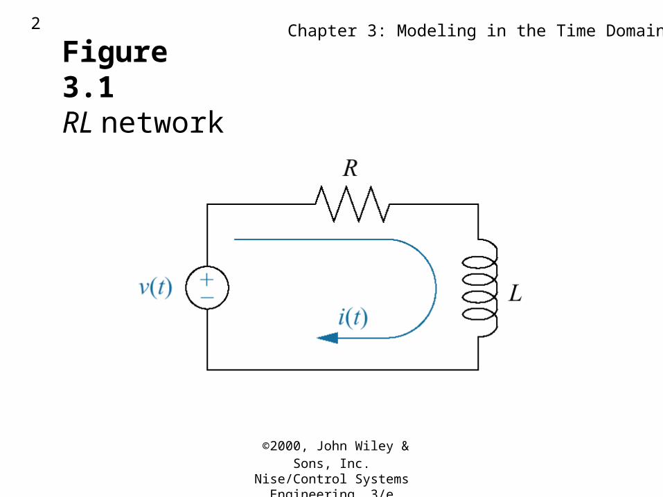
Figure 3.1RL network
©2000, John Wiley & Sons, Inc.
Nise/Control Systems Engineering, 3/e
Chapter 3: Modeling in the Time Domain3
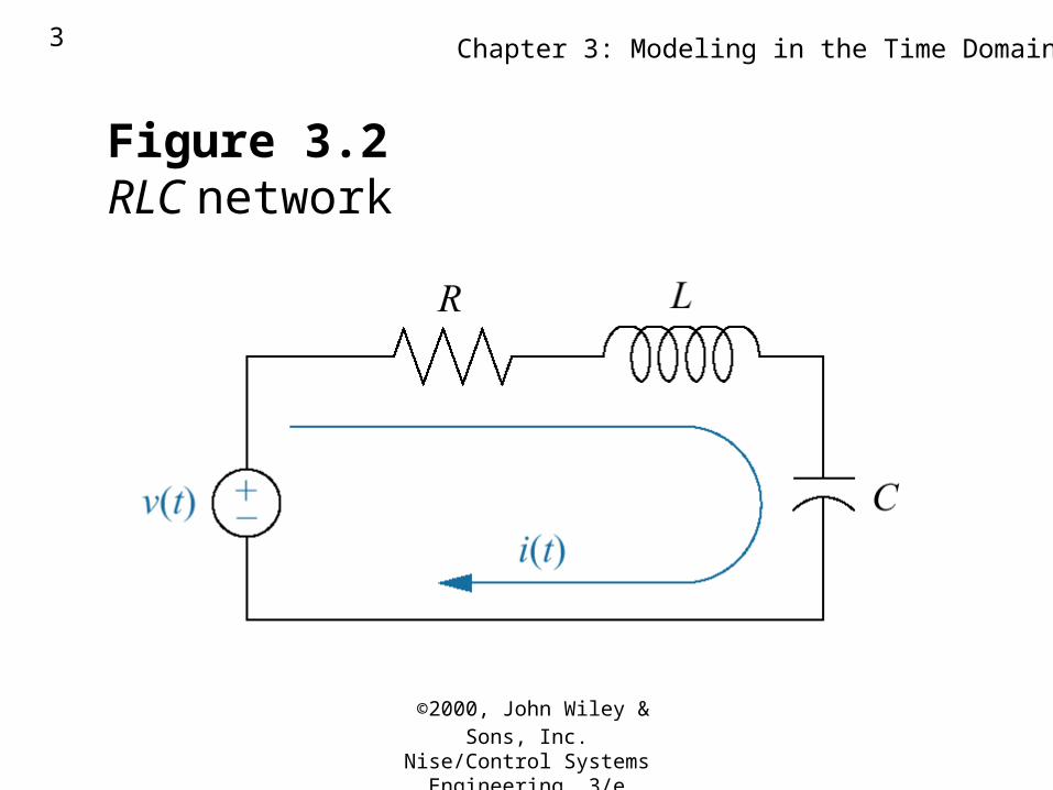
Figure 3.2RLC network
©2000, John Wiley & Sons, Inc.
Nise/Control Systems Engineering, 3/e
Chapter 3: Modeling in the Time Domain4
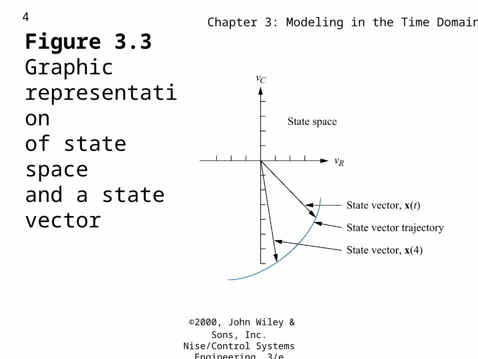
Figure 3.3Graphic representationof state spaceand a state vector
©2000, John Wiley & Sons, Inc.
Nise/Control Systems Engineering, 3/e
Chapter 3: Modeling in the Time Domain5
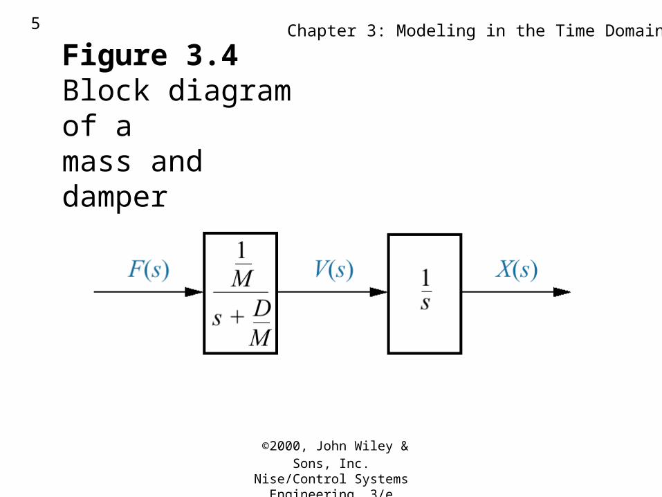
Figure 3.4Block diagram of amass and damper
©2000, John Wiley & Sons, Inc.
Nise/Control Systems Engineering, 3/e
Chapter 3: Modeling in the Time Domain6
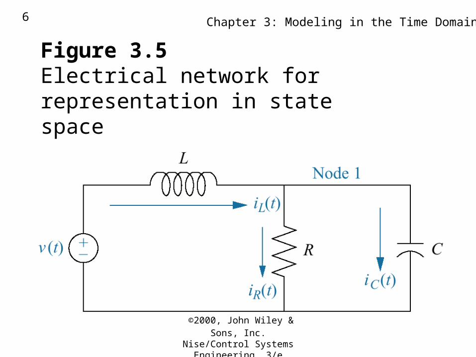
Figure 3.5Electrical network forrepresentation in statespace
©2000, John Wiley & Sons, Inc.
Nise/Control Systems Engineering, 3/e
Chapter 3: Modeling in the Time Domain7
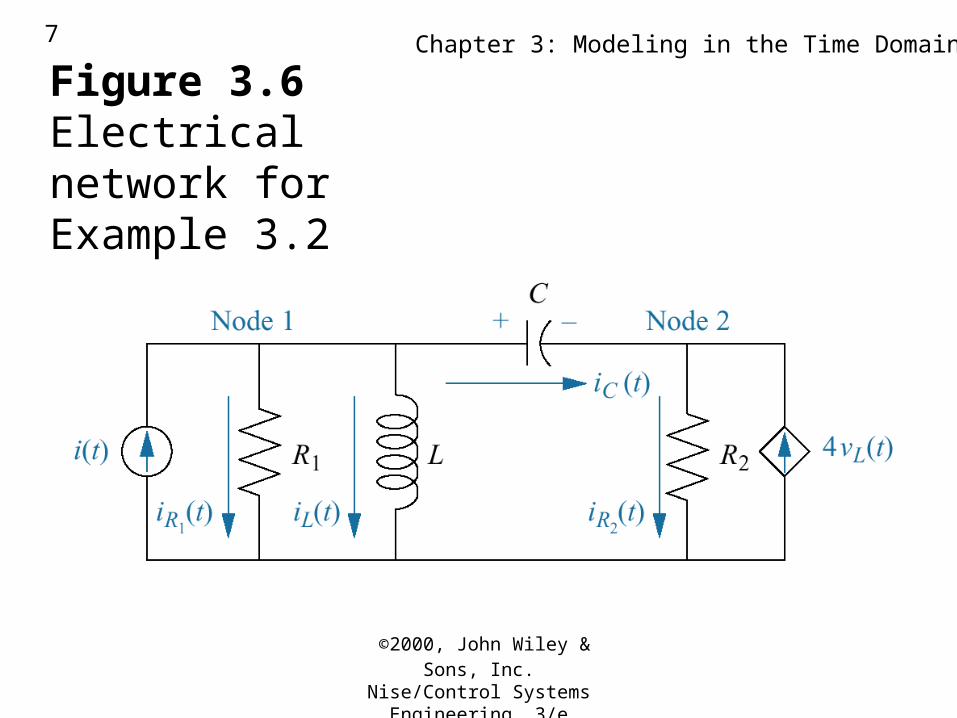
Figure 3.6Electrical network forExample 3.2
©2000, John Wiley & Sons, Inc.
Nise/Control Systems Engineering, 3/e
Chapter 3: Modeling in the Time Domain8
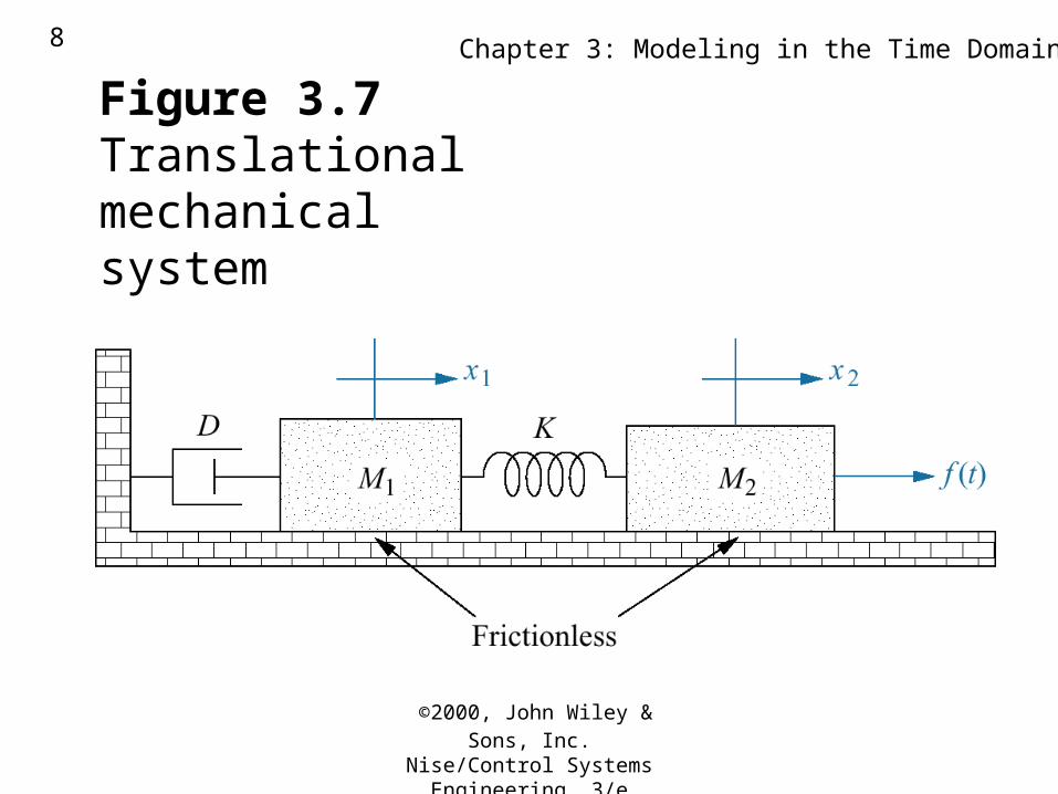
Figure 3.7Translationalmechanical system
©2000, John Wiley & Sons, Inc.
Nise/Control Systems Engineering, 3/e
Chapter 3: Modeling in the Time Domain9
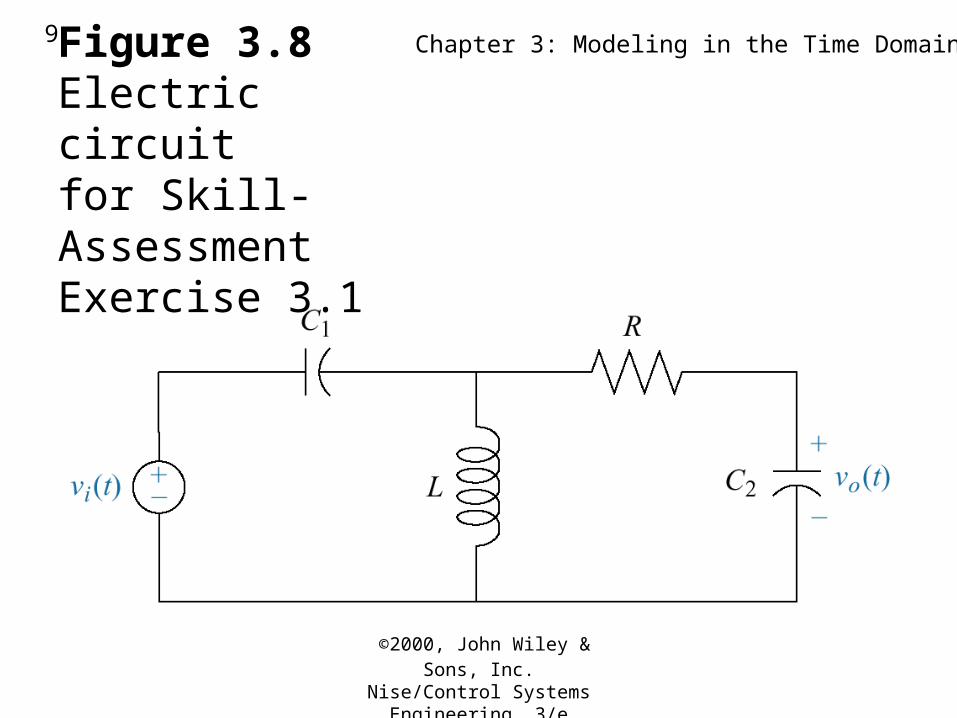
Figure 3.8Electric circuitfor Skill-AssessmentExercise 3.1
©2000, John Wiley & Sons, Inc.
Nise/Control Systems Engineering, 3/e
Chapter 3: Modeling in the Time Domain10
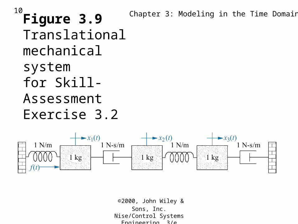
Figure 3.9Translationalmechanical systemfor Skill-AssessmentExercise 3.2
©2000, John Wiley & Sons, Inc.
Nise/Control Systems Engineering, 3/e
Chapter 3: Modeling in the Time Domain11
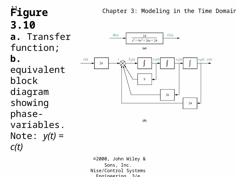
Figure 3.10a. Transfer function;b. equivalentblock diagram showingphase-variables.Note: y(t) = c(t)
©2000, John Wiley & Sons, Inc.
Nise/Control Systems Engineering, 3/e
Chapter 3: Modeling in the Time Domain12
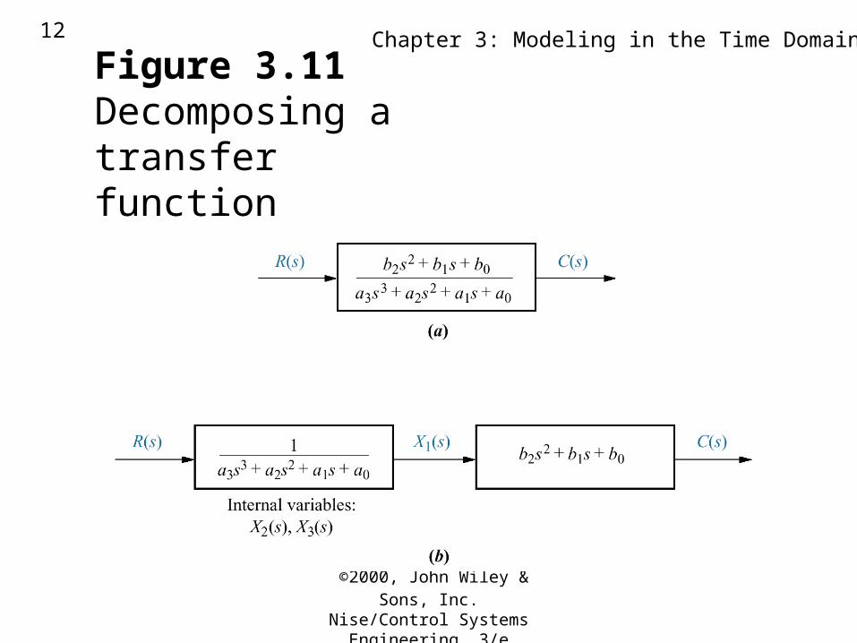
Figure 3.11Decomposing atransfer function
©2000, John Wiley & Sons, Inc.
Nise/Control Systems Engineering, 3/e
Chapter 3: Modeling in the Time Domain13
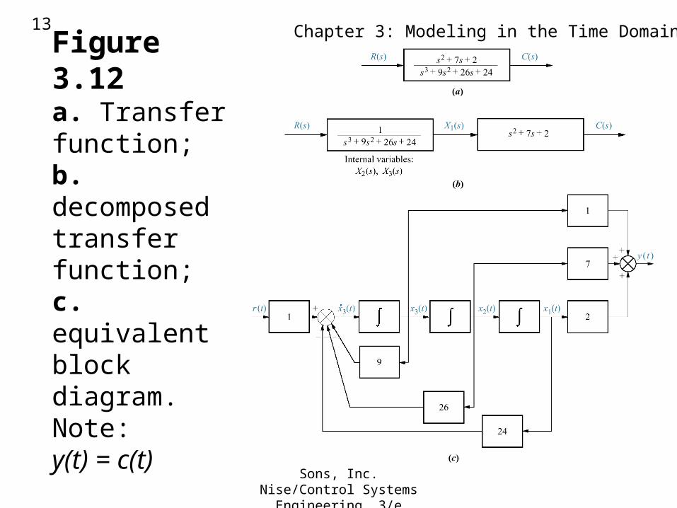
Figure 3.12a. Transfer function;b. decomposedtransfer function;c. equivalent block diagram. Note:y(t) = c(t)
©2000, John Wiley & Sons, Inc.
Nise/Control Systems Engineering, 3/e
Chapter 3: Modeling in the Time Domain14
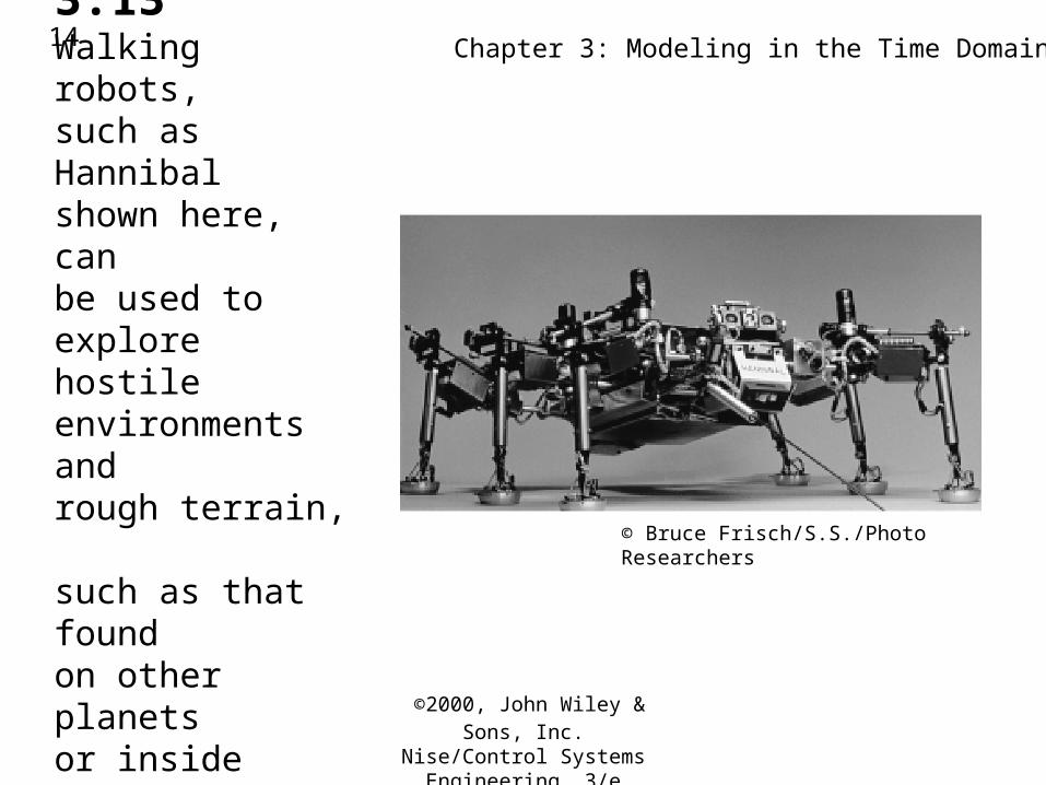
Figure 3.13Walking robots,such as Hannibalshown here, canbe used to explore hostile environments andrough terrain, such as that foundon other planets or insidevolcanoes.
© Bruce Frisch/S.S./Photo Researchers
©2000, John Wiley & Sons, Inc.
Nise/Control Systems Engineering, 3/e
Chapter 3: Modeling in the Time Domain15
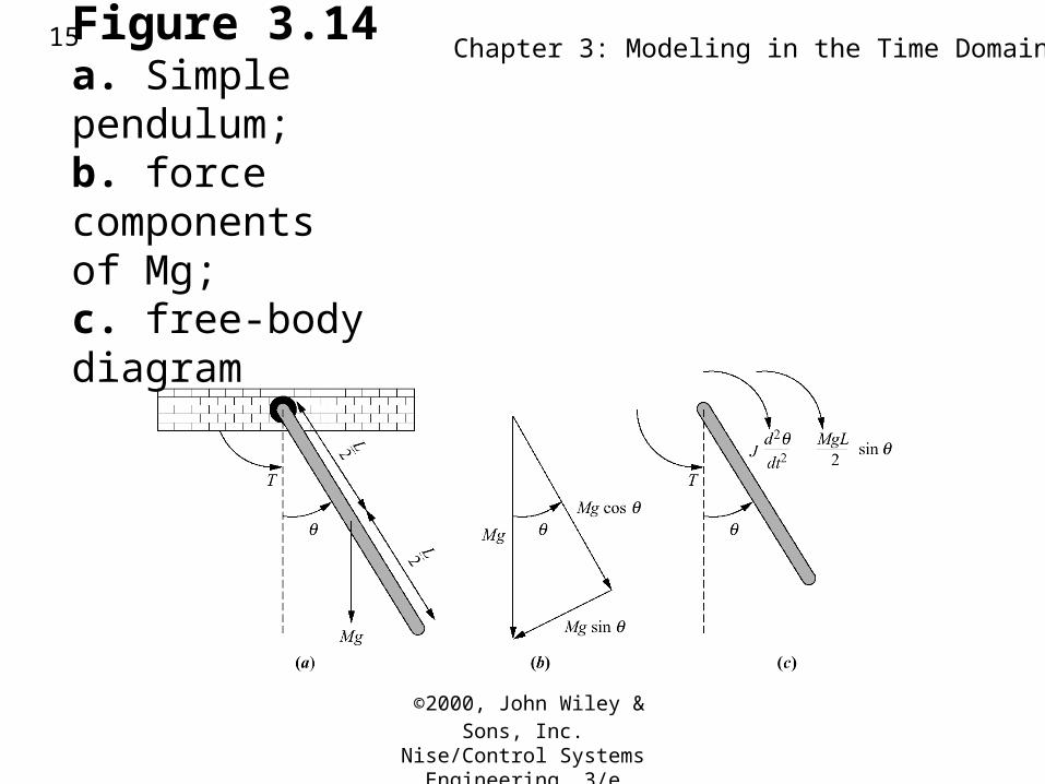
Figure 3.14a. Simple pendulum;b. force componentsof Mg;c. free-body diagram
©2000, John Wiley & Sons, Inc.
Nise/Control Systems Engineering, 3/e
Chapter 3: Modeling in the Time Domain16
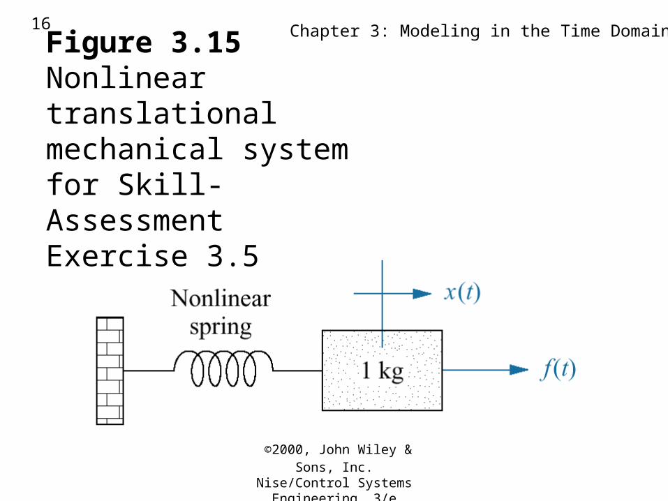
Figure 3.15Nonlinear translationalmechanical systemfor Skill-AssessmentExercise 3.5
©2000, John Wiley & Sons, Inc.
Nise/Control Systems Engineering, 3/e
Chapter 3: Modeling in the Time Domain17
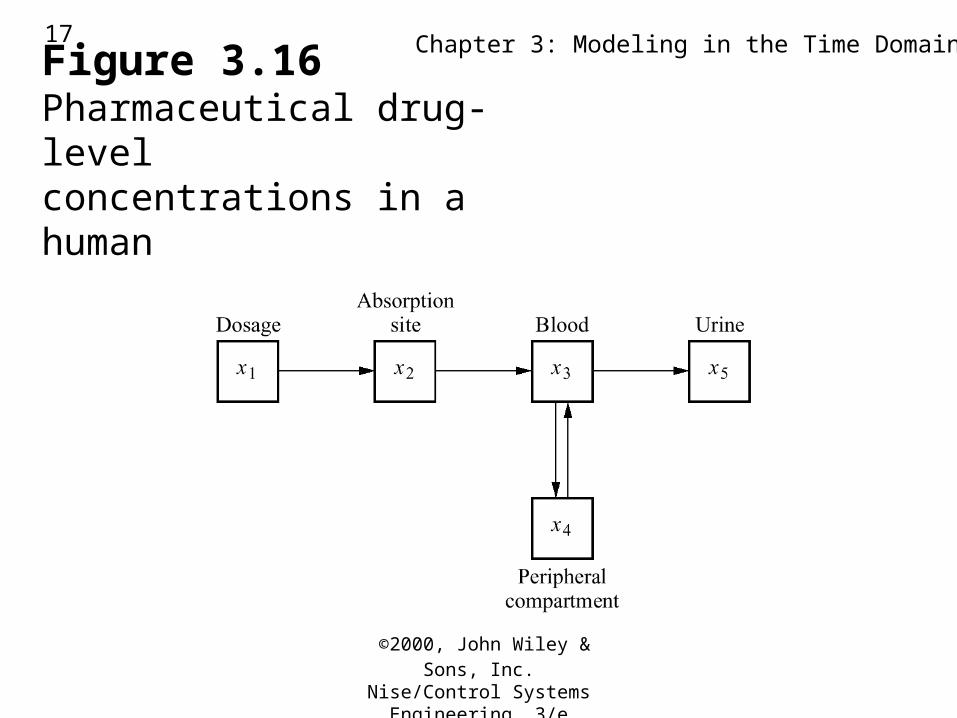
Figure 3.16Pharmaceutical drug-levelconcentrations in a human
©2000, John Wiley & Sons, Inc.
Nise/Control Systems Engineering, 3/e
Chapter 3: Modeling in the Time Domain18
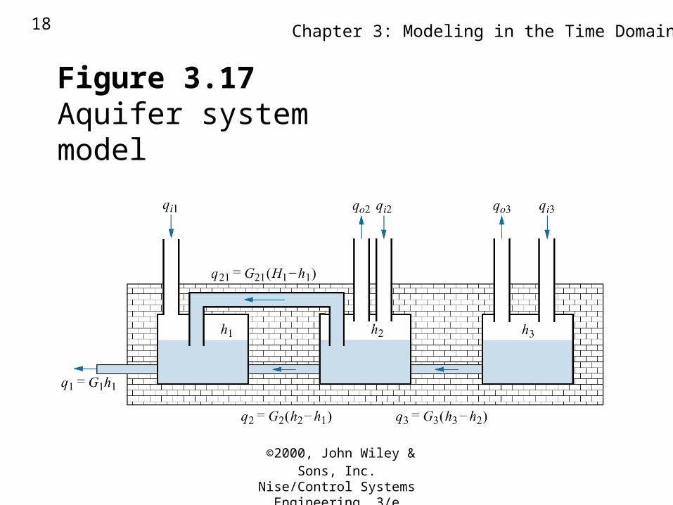
Figure 3.17Aquifer system model
©2000, John Wiley & Sons, Inc.
Nise/Control Systems Engineering, 3/e
Chapter 3: Modeling in the Time Domain19
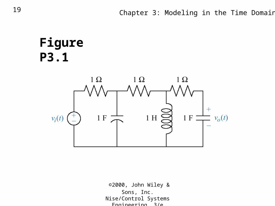
Figure P3.1
©2000, John Wiley & Sons, Inc.
Nise/Control Systems Engineering, 3/e
Chapter 3: Modeling in the Time Domain20
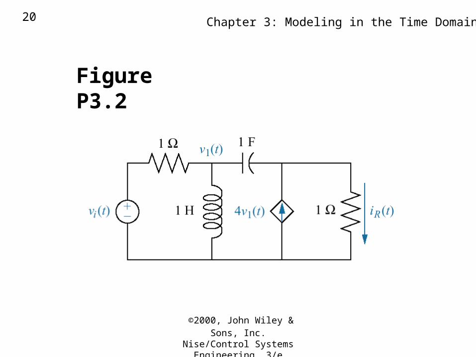
Figure P3.2
©2000, John Wiley & Sons, Inc.
Nise/Control Systems Engineering, 3/e
Chapter 3: Modeling in the Time Domain21
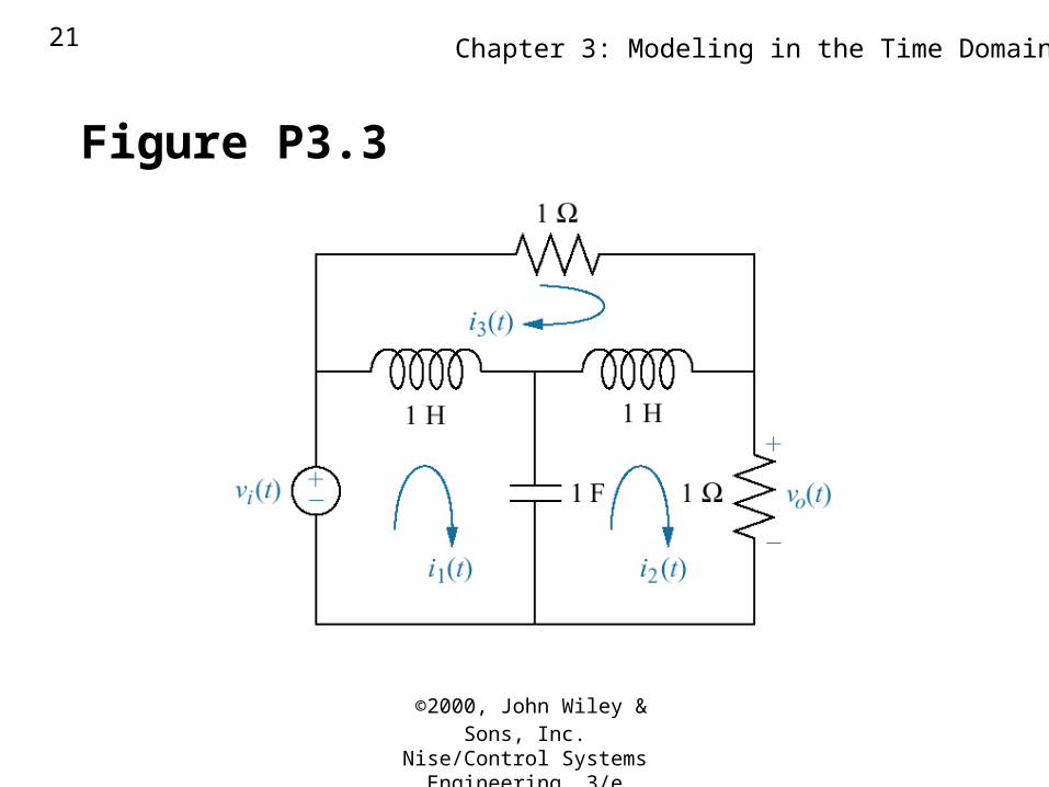
Figure P3.3
©2000, John Wiley & Sons, Inc.
Nise/Control Systems Engineering, 3/e
Chapter 3: Modeling in the Time Domain22
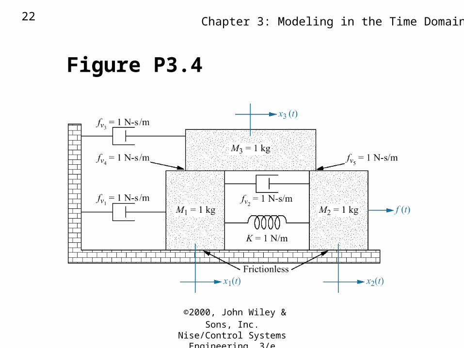
Figure P3.4
©2000, John Wiley & Sons, Inc.
Nise/Control Systems Engineering, 3/e
Chapter 3: Modeling in the Time Domain23
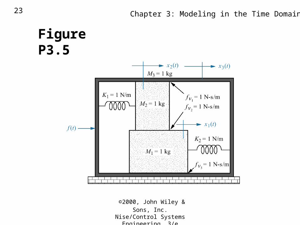
Figure P3.5
©2000, John Wiley & Sons, Inc.
Nise/Control Systems Engineering, 3/e
Chapter 3: Modeling in the Time Domain24
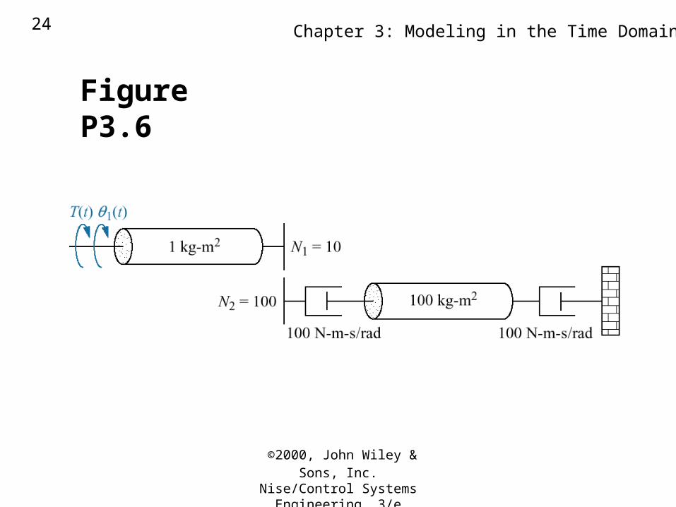
Figure P3.6
©2000, John Wiley & Sons, Inc.
Nise/Control Systems Engineering, 3/e
Chapter 3: Modeling in the Time Domain25
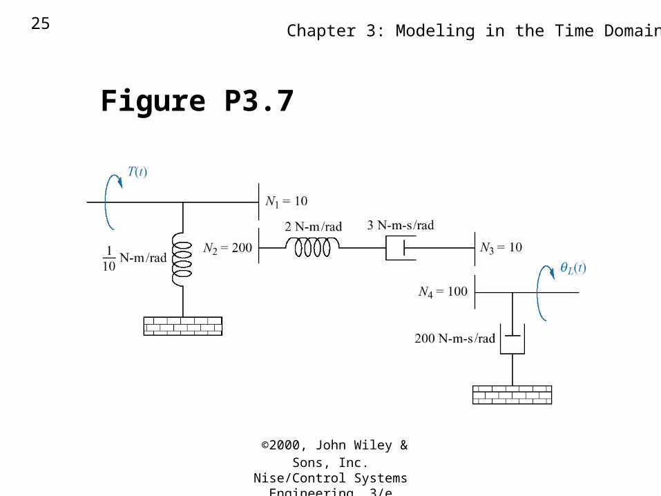
Figure P3.7
©2000, John Wiley & Sons, Inc.
Nise/Control Systems Engineering, 3/e
Chapter 3: Modeling in the Time Domain26
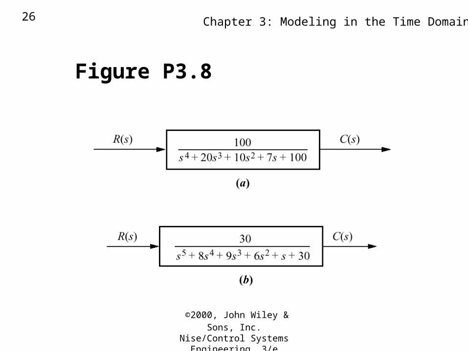
Figure P3.8
©2000, John Wiley & Sons, Inc.
Nise/Control Systems Engineering, 3/e
Chapter 3: Modeling in the Time Domain27
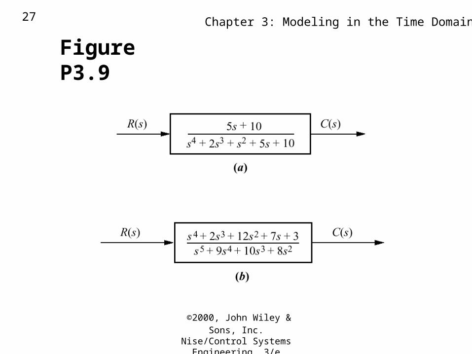
Figure P3.9
©2000, John Wiley & Sons, Inc.
Nise/Control Systems Engineering, 3/e
Chapter 3: Modeling in the Time Domain28
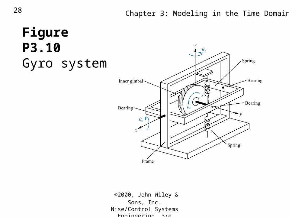
Figure P3.10 Gyro system
©2000, John Wiley & Sons, Inc.
Nise/Control Systems Engineering, 3/e
Chapter 3: Modeling in the Time Domain29
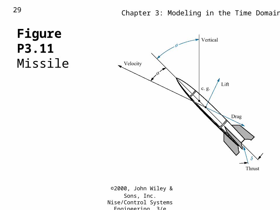
Figure P3.11
Missile
©2000, John Wiley & Sons, Inc.
Nise/Control Systems Engineering, 3/e
Chapter 3: Modeling in the Time Domain30
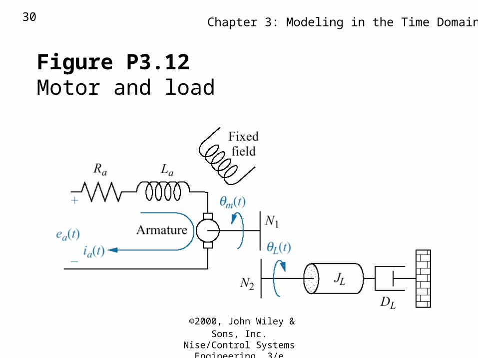
Figure P3.12 Motor and load
©2000, John Wiley & Sons, Inc.
Nise/Control Systems Engineering, 3/e
Chapter 3: Modeling in the Time Domain31
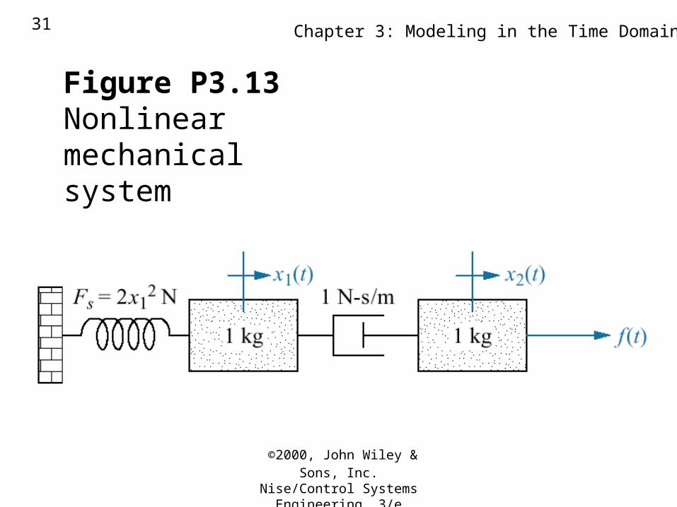
Figure P3.13 Nonlinear mechanicalsystem
©2000, John Wiley & Sons, Inc.
Nise/Control Systems Engineering, 3/e
Chapter 3: Modeling in the Time Domain32
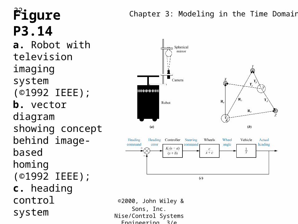
Figure P3.14a. Robot withtelevision imagingsystem(©1992 IEEE);b. vector diagramshowing conceptbehind image-basedhoming (©1992 IEEE);c. heading controlsystem
©2000, John Wiley & Sons, Inc.
Nise/Control Systems Engineering, 3/e
Chapter 3: Modeling in the Time Domain33
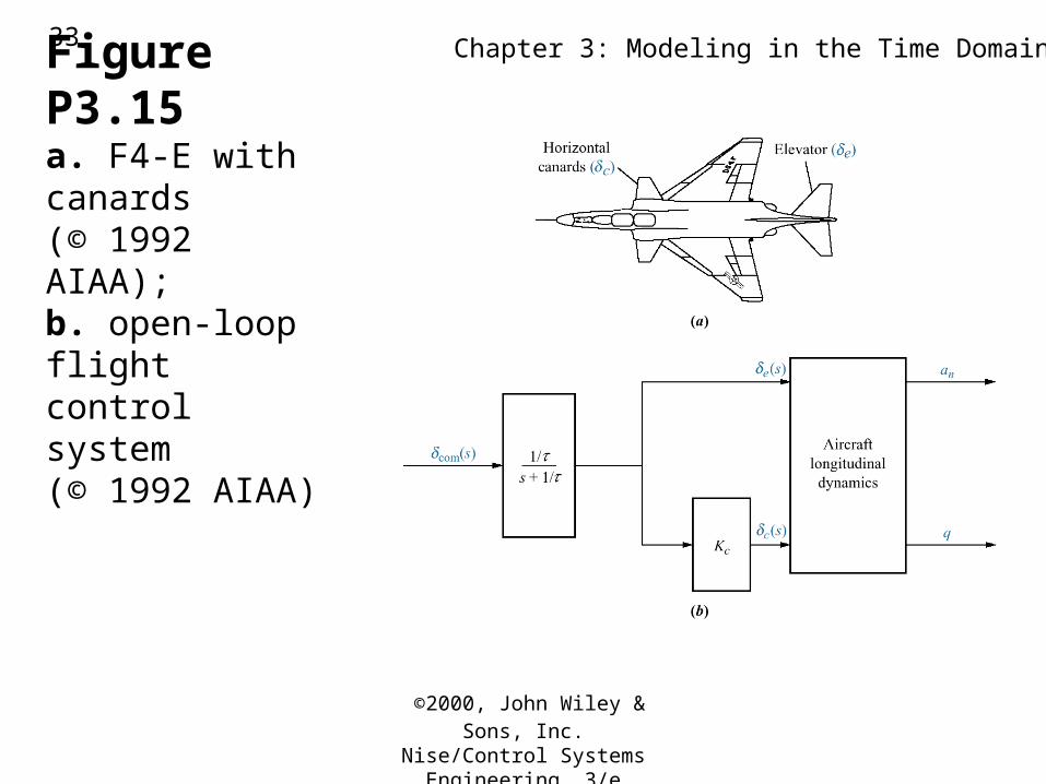
Figure P3.15a. F4-E with canards(© 1992 AIAA);b. open-loop flightcontrol system(© 1992 AIAA)
©2000, John Wiley & Sons, Inc.
Nise/Control Systems Engineering, 3/e
Chapter 3: Modeling in the Time Domain34
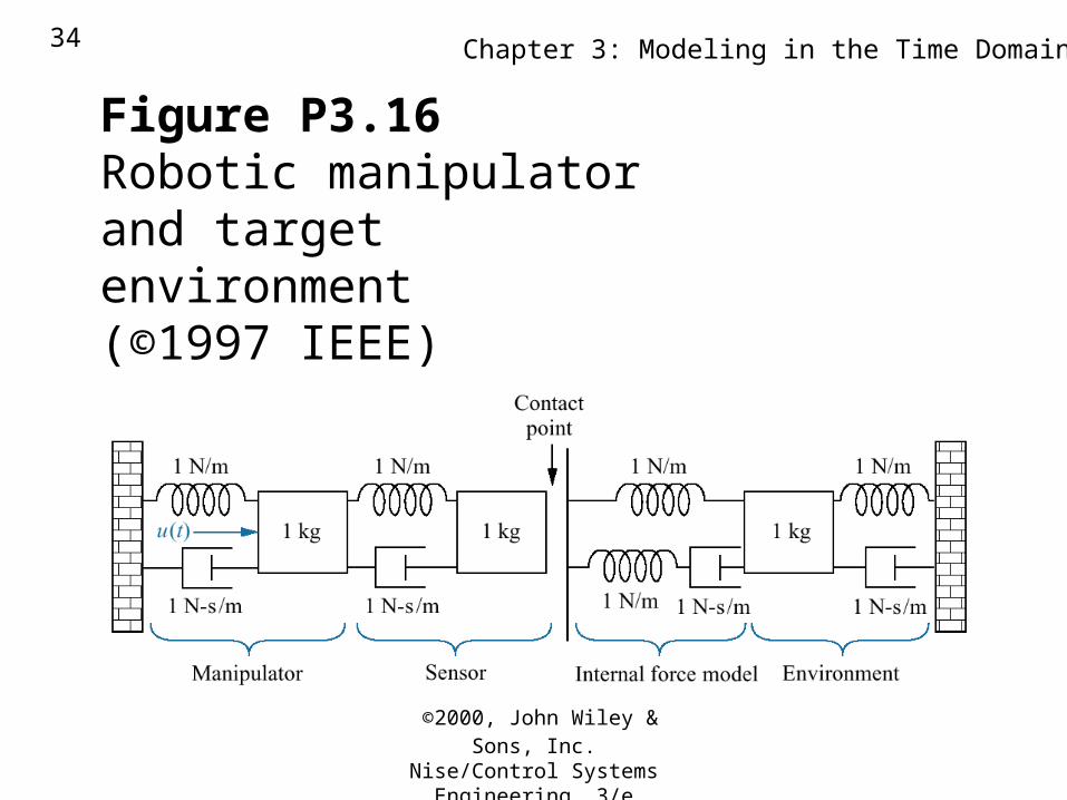
Figure P3.16 Robotic manipulatorand targetenvironment(©1997 IEEE)