chapter 1 ie252-v2fac.ksu.edu.sa/sites/default/files/chapter_1_ie252-v2.pdf3-assembly or joining...
TRANSCRIPT

9/1
/20
14
: M
orp
ho
log
ic P
roce
ss
IE2
52
Chapter 1
Morphologic Process Model
Ch
ap
ter
1:
Mo
rph
olo
gic
Pro
cess
Mo
de
l -IE
1

9/1
/20
14
: M
orp
ho
log
ic P
roce
ss
IE2
52
Chapter 1
Morphologic Process Model
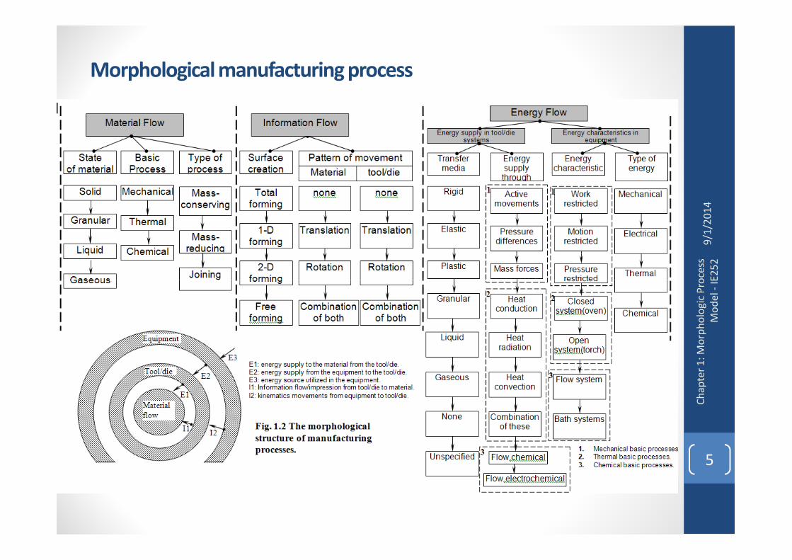
Chapter 1: Morphological manufacturing process.
1.1 Material flow system
1.1.1 Types of material flow
Ch
ap
ter
1:
Mo
rph
olo
gic
Pro
cess
Mo
de
l -IE
2
1.1.1 Types of material flow
1.1.2 State of material
1.1.3 Basic process
1.1.4 Illustrated examples
1.2 Energy flow system.
1.2.1 Energy flow for mechanical basic process
1.2.2 Energy flow in thermal basic processes
1.2.3 Energy flow for chemical basic processes
1.3 Information flow system

9/1
/20
14
: M
orp
ho
log
ic P
roce
ss
IE2
52
Morphological manufacturing process ??
�The term process in general can be defined as a change in the
properties of an object, including geometry, hardness, state,
information content. According to Altingmorphological process model
[1.1]
ProcessChange in properties
and or geometry
Material (Output)
Energy (Output)
Information
(Output)
Material (input)
Energy (input)
Information
(input)
Ch
ap
ter
1:
Mo
rph
olo
gic
Pro
cess
Mo
de
l -IE
3
Fig. 1.1 Simplify morphological structure of manufacturing
process [1.1].

9/1
/20
14
: M
orp
ho
log
ic P
roce
ss
IE2
52
Morphological manufacturing process ??
�The term process in general can be defined as a change in the
properties of an object, including geometry, hardness, state,
information content. According to Altingmorphological process model
[1.1].
�Any change in product properties requires three essential changes in
material, energy, and information.
Ch
ap
ter
1:
Mo
rph
olo
gic
Pro
cess
Mo
de
l -IE
4
Material
Process
Material (Mi)
Shape or
Information(Si)
Material (Mo)
Shape or
Information (So)
Energy (Ei)
Energy (Eo)
Energy Flow
Shape Flow
Material Flow
Control lines
Fig. 1.1 Morphological structure of manufacturing process [1.1].
9/1
/20
14
: M
orp
ho
log
ic P
roce
ss
IE2
52
Morphological manufacturing process
Ch
ap
ter
1:
Mo
rph
olo
gic
Pro
cess
Mo
de
l -IE
5

9/1
/20
14
: M
orp
ho
log
ic P
roce
ss
IE2
52
1.1 Morphological manufacturing process
1.2 Material flow system
Types of material flow ??
1- Mass conserving process (dm=0);
Metal forming processes (IE252)
2- Mass reducing process (dm<0);
Metal cutting processes (IE352)
3- Assembly or joining processes (dm>0);
Welding process (IE252)
Ch
ap
ter
1:
Mo
rph
olo
gic
Pro
cess
Mo
de
l -IE
6
Welding process (IE252)

9/1
/20
14
: M
orp
ho
log
ic P
roce
ss
IE2
52
1.1 Morphological manufacturing process
1.2 Material flow system
State of material ??
State of processed material can be :
�Solid,
�Fluid,
�Gaseous or
�Granular ‘homogeneous e.g. pure metal and
heterogeneous e.g. mechanical mixture’
Ch
ap
ter
1:
Mo
rph
olo
gic
Pro
cess
Mo
de
l -IE
7
heterogeneous e.g. mechanical mixture’

9/1
/20
14
: M
orp
ho
log
ic P
roce
ss
IE2
52
1.1 Morphological manufacturing process
1.2 Material flow system
Basic process ??
�Basic process is the process that creates changes in
geometry and/or properties of material.
�Manufacturing processes consist of a series of basic
processes, which in general can be divided into three
phases; pre-processing, processing, then post
processing).
Ch
ap
ter
1:
Mo
rph
olo
gic
Pro
cess
Mo
de
l -IE
8
processing).

9/1
/20
14
: M
orp
ho
log
ic P
roce
ss
IE2
52
1.1 Morphological manufacturing process
1.2 Material flow system
Basic process ??
�Categories of basic process:
1. Mechanical type, which covers:
•Plastic/elastic deformation.
•Fracture (brittle or ductile type).
•Flow/mixing process.
Ch
ap
ter
1:
Mo
rph
olo
gic
Pro
cess
Mo
de
l -IE
9
•Flow/mixing process.
2. Thermal type, which covers:
•Heating.
•Cooling.
•Melting.
•Solidification.
•Evaporation.
3. Chemical, which covers;
•Solution/dissolution.
•Combustion.
•Hardening.
•Phase transformation, diffusion.
9/1
/20
14
: M
orp
ho
log
ic P
roce
ss
IE2
52
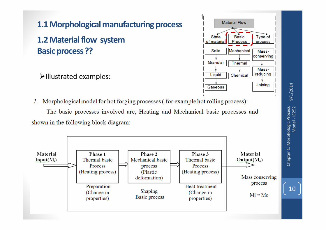
1.1 Morphological manufacturing process
1.2 Material flow system
Basic process ??
�Illustrated examples:
Ch
ap
ter
1:
Mo
rph
olo
gic
Pro
cess
Mo
de
l -IE
10

9/1
/20
14
: M
orp
ho
log
ic P
roce
ss
IE2
52
1.1 Morphological manufacturing process
1.2 Material flow system
Basic process ??
�Illustrated examples:
Ch
ap
ter
1:
Mo
rph
olo
gic
Pro
cess
Mo
de
l -IE
11

9/1
/20
14
: M
orp
ho
log
ic P
roce
ss
IE2
52
1.1 Morphological manufacturing process
1.3 Energy flow system
Ch
ap
ter
1:
Mo
rph
olo
gic
Pro
cess
Mo
de
l -IE
12

9/1
/20
14
: M
orp
ho
log
ic P
roce
ss
IE2
52
1.1 Morphological manufacturing process
1.3 Energy flow system
�To carry out the basic process required,
the provided energy must be transmitted
to the work material via different media.
�This covers two sub-systems: energy
supply in tool/die systems and energy
equipment characteristics
Ch
ap
ter
1:
Mo
rph
olo
gic
Pro
cess
Mo
de
l -IE
13

9/1
/20
14
: M
orp
ho
log
ic P
roce
ss
IE2
52
1.1 Morphological manufacturing process
1.3 Energy flow system
�In tool/die systems it describes how
energy is supplied to material and to the
transfer media used in manufacturing
process.
�The equipment system describes the
characteristics of the energy supplied
from the equipment and type of energy
Ch
ap
ter
1:
Mo
rph
olo
gic
Pro
cess
Mo
de
l -IE
14
from the equipment and type of energy
used in manufacturing processes.

9/1
/20
14
: M
orp
ho
log
ic P
roce
ss
IE2
52
1.1 Morphological manufacturing process
1.3 Energy flow system
Energy flow for mechanical basic
processPrimary basic process are: plastic and/or
elastic deformations, brittle or ductile
fracture, and flow
Ch
ap
ter
1:
Mo
rph
olo
gic
Pro
cess
Mo
de
l -IE
15

9/1
/20
14
: M
orp
ho
log
ic P
roce
ss
IE2
52
1.1 Morphological manufacturing process
1.3 Energy flow system
Energy flow for mechanical basic
process
Mechanical energy sources:•Mechanical energy (Translation – Rotation – Combinations of
these).
•Potential energy (Gravity – Elastic).
•Pressure in a medium (Kinetic energy in molecules).Vacuum.
Electrical energy sources:•Discharge between two electrodes.
•Electromagnetic fields.
Ch
ap
ter
1:
Mo
rph
olo
gic
Pro
cess
Mo
de
l -IE
16
•Electromagnetic fields.
•Magnetostrictive effects. (Change in dimensions of metals due
to magnetic field).
•Piezoelectric effects. (Discharge generation of some crystals
under compression or tension load).
Chemical energy sources:Here chemical energy is used and converted to mechanical
energy by different ways, like
•Combustion.
•Combustion and pressure increased which result in motion
(e.g. internal combustion engine).
•Explosive. (Explosive forming process, welding, and
compaction).
Thermal energy sources:Here the thermal energy used to generate mechanical energy
through utilizing the thermal expansion of material to provide
relative motions or pressure in working media.

9/1
/20
14
: M
orp
ho
log
ic P
roce
ss
IE2
52
1.1 Morphological manufacturing process
1.3 Energy flow system
Energy flow in thermal basic
processes�Heating energy is used as primary basic
thermal process. Melting or evaporation is
used to generate heat energy.
�The electric, mechanical, or chemical energy
used is converted into heat energy to be
utilized in the selected manufacturing process.
Ch
ap
ter
1:
Mo
rph
olo
gic
Pro
cess
Mo
de
l -IE
17
utilized in the selected manufacturing process.

9/1
/20
14
: M
orp
ho
log
ic P
roce
ss
IE2
52
1.1 Morphological manufacturing process
1.3 Energy flow system
Energy flow in thermal basic
processes
Heat transfer:Conduction, radiation, convection and mass transfer carry
out heat transfer in these processes.
Heating sources:•Heating source based on electric energy:
1.Electrical conduction (resistance).
2.Induction.
3.Dielectric loss.
Ch
ap
ter
1:
Mo
rph
olo
gic
Pro
cess
Mo
de
l -IE
18
3.Dielectric loss.
4.Arcing (discharge between electrodes).
5.Sparking.
6.Electronic beams.
7.Lasers.
•Heat source based on chemical energy1.Combustions.
2.Exothermic chemical reactions (e.g. Fe3O4 reaction
with AL plus helium or argon gas to generate arc-
plasma torches).
•Heat source based on mechanical energy1.Heat generation by friction (e.g. friction welding
process).
2.Heat generation by internal hysteresis losses (e.g.
ultra-sonic welding process of plastic materials).
•Heat source based on thermal energy

9/1
/20
14
: M
orp
ho
log
ic P
roce
ss
IE2
52
1.1 Morphological manufacturing process
1.3 Energy flow system
Energy flow for chemical basic
processes
This covers chemical basic
processes like solution/dissolution,
deposition, diffusion, phase
transformation.
Ch
ap
ter
1:
Mo
rph
olo
gic
Pro
cess
Mo
de
l -IE
19
�Chemical solution (dissolution),
e.g. etching and polishing
processes of metals.
�Phase transformation and
diffusion is important process in
which heat treatment of metals are
used in industries.

9/1
/20
14
: M
orp
ho
log
ic P
roce
ss
IE2
52
1.1 Morphological manufacturing process
1.4 Information flow system
The creation of the desired geometry takes
place for a given basic process by the
interaction between the medium of transfer
together with the contour of the desired
geometry Gi and the pattern of motions for
the medium of transfer (G1, …, Gi) and the
work material (A).
Ch
ap
ter
1:
Mo
rph
olo
gic
Pro
cess
Mo
de
l -IE
20

9/1
/20
14
: M
orp
ho
log
ic P
roce
ss
IE2
52
1.1 Morphological manufacturing process
1.4 Information flow system
Surface creation carried out by the four
methods, is given as follows:
•Free forming: Here the medium of transfer does
not contain the desired geometry (i.e. the
surface/geometry is generated by stress fields, like
torsion process).
•Two-dimension forming: Here the medium of
transfer contains a point or a surface element of the
Ch
ap
ter
1:
Mo
rph
olo
gic
Pro
cess
Mo
de
l -IE
21
transfer contains a point or a surface element of the
desired geometry (two relative motions are required
to generate the surface, e.g. turning process).
•One-dimension forming: Here the medium of
transfer contains a producer or equipment (a line or
surface area along the line) required to create the
product or required surface. This requires one
relative motion to generate the required surface
(strip rolling process is one dimension forming
which is mainly forming along the rolling direction).
Total forming: Here the medium of transfer
contains the whole surface of the desired geometry.
No relative motion is required in this case, like
forging process.

9/1
/20
14
: M
orp
ho
log
ic P
roce
ss
IE2
52
1.1 Morphological manufacturing process
1.4 Information flow system
Surface creation carried out by the four
methods, is given as follows:
•Free forming: Here the medium of transfer does
not contain the desired geometry (i.e. the
surface/geometry is generated by stress fields, like
torsion process).
•Two-dimension forming: Here the medium of
transfer contains a point or a surface element of the
Ch
ap
ter
1:
Mo
rph
olo
gic
Pro
cess
Mo
de
l -IE
22
transfer contains a point or a surface element of the
desired geometry (two relative motions are required
to generate the surface, e.g. turning process).
•One-dimension forming: Here the medium of
transfer contains a producer or equipment (a line or
surface area along the line) required to create the
product or required surface. This requires one
relative motion to generate the required surface
(strip rolling process is one dimension forming
which is mainly forming along the rolling direction).
Total forming: Here the medium of transfer
contains the whole surface of the desired geometry.
No relative motion is required in this case, like
forging process.

9/1
/20
14
: M
orp
ho
log
ic P
roce
ss
IE2
52
End Of Chapter 1:
Morphological manufacturing process
Ch
ap
ter
1:
Mo
rph
olo
gic
Pro
cess
Mo
de
l -IE
23