chapter 1 routine maintenance and servicing -...
TRANSCRIPT

1•1
Chapter 1 Routine maintenance and servicingContentsAir conditioning system refrigerant check 14Air filter renewal 26Automatic transmission fluid level check 10Automatic transmission fluid renewal 29Auxiliary drivebelt checking and renewal 21Battery check 6Brake fluid renewal 30Clutch adjustment check and control mechanism lubrication 22Coolant renewal 31Driveshaft gaiter check 12Electrical system check 5Emission control systems check 20Engine oil and filter renewal 8Fluid level checks .: 3Front brake pad condition check 13Fuel filter renewal - carburettor models 17Fuel filter renewal - fuel injection models 32Hinge and lock lubrication 27
Degrees of difficulty
Hose and fluid leak check 9Idle speed and mixture check and adjustment 19Ignition system check 18intensive maintenance 2Introduction 1Manual transmission oil level check 28Manual transmission oil renewal 34Rear brake pad condition check - models with rear disc brakes . . . 24Rear brake shoe condition check - models with rear drum brakes . 23Road test 25Spark plug renewal 16Specifications See end of ChapterSteering and suspension check 11Timing belt renewal 33Tyre checks 4Valve clearance check and adjustment -1124 cc and 1360 cc
models 15Wiper blade check 7
Easy, suitable fornovice with littleexperience
Fairly easy, suitablefor beginner withsome experience
Fairty difficult, suitablefor competent DIYmechanic
Difficult, suitable forexperienced DIYmechanic
Very difficult,suitable for expert DIYor professional

Lubricants, Fluids & Capacities
Lubricants and fluidsComponent or system
1 Engine
2 Cooling system
3 Manual transmission
4 Automatic transmission
5 Braking system
6 Power steering
Capacities
Engine oilExcluding filter:
1124 cc and 1360 cc models 3.2 litres1580 cc and 1905 cc models 4.5 litres1761 cc models 4.4 litres1998 cc models 4.7 litres
Including filter:1124 cc and 1360 cc models 3.5 litres1580 cc and 1905 cc models 5.0 litres1761 cc models 4.9 litres1998 cc models 5.4 litres
Difference between "MIN" and "MAX" dipstick marks (approximate):Models without air conditioning 1.5 litresModels with air conditioning 1.3 litres
Lubricant type/specification
Multigrade engine oil, viscosity SAE 10W/40or 15W/50, to API SG/CD
Ethylene glycol-based antifreeze
Total transmission BV75/80W
Dexron type IIATF
Total Universal Brake and Clutch Fluid
Dexron type II ATF
Cooling system1124 cc and 1360 cc models:
Models without air conditioning 6.5 litresModels with air conditioning 7.5 litres
1580 cc and 1905 cc models:Models with manual transmission 7.5 litresModels with automatic transmission 8.0 litres
1761 cc models 8.0 litres1998 cc models 8.5 litres
TransmissionManual 2.0 litresAutomatic:
From dry 6.2 litresDrain and refill 2.4 litres
Power-assisted steering 1.7 litres
Fuel tank 56 litres
1•2

Maintenance scheduleMaintenance schedule1 The maintenance intervals in this manual are provided on theassumption that you, not the dealer, will be carrying out the work.These are the minimum maintenance intervals recommended by themanufacturer for vehicles driven daily. If you wish to keep your vehiclein peak condition at all times, you may wish to perform some of theseprocedures more often. We encourage frequent maintenance, becauseit enhances the efficiency, performance and resale value of yourvehicle. If the vehicle is driven in dusty areas, used to tow a trailer, or is
driven frequently at slow speeds (idling in traffic) or on short journeys,more frequent maintenance intervals are recommended.2 Vehicles which cover a low mileage (less than 12 000 miles/20 000 kmper year) should be serviced following the time interval instead of themileage interval. This is necessary because many lubricants and fluids, aswell as some components, deteriorate with time as much as with use.3 When the vehicle is new, it should be serviced by a factory-authoriseddealer service department, in order to preserve the factory warranty.
1•3
Every 250 miles (400 km) or weekly• Check the engine oil level (Section 3)• Check the engine coolant level (Section 3)• Check the brake fluid level (Section 3)• Check the power steering fluid level (Section 3)• Check the screen washer fluid level (Section 3)• Check the tyres for wear or damage (Section 4)• Check and adjust the tyre pressures (Section 4)• Check the condit ion of the battery (Section 6)• Check the operation of the horn, all lights, and the wipers
and washers (Sections 5 and 7)
Every 6000 miles (10 000 km) or6 months - whichever comes first• Renew the engine oil and filter* (Section 8)• Check all components and hoses for fluid leaks (Section 9)• Check the automatic transmission fluid level (Section 10)• Check the steering and suspension components for
condition and security (Section 11)• Check the condition of the driveshaft gaiters (Section 12)• Check the condition of the front brake pads, and renew if
necessary (Section 13)The manufacturer specifies that the oil filter should be renewed at thefirst 6000 mile service, and then at 12 000 miles intervals, with only theoil being drained and renewed every 6000 miles. Owners may prefer tocarry out filter renewal at the 6000-mile interval, as a precautionary task.
Every 12 000 miles (20 000 km) or12 months - whichever comes firstIn addition to all the items listed above, carry out the following:• Check the condi t ion of the air condi t ioning system
refrigerant - where applicable (see Section 14)• Check and, if necessary, adjust the valve clearances -
1124 cc and 1360 cc models (Section 15)*• Renew the spark plugs (Section 16)• Renew the fuel filter - carburettor models (Section 17)• Check the ignition system and ignition timing (Section 18)• Check the idle speed and mixture adjustment (Section 19)• Check the condition of the emission control system hoses
and components (Section 20)• Check the condit ion of the auxiliary drivebelt, and renew if
necessary (Section 21)• Check the clutch mechanism adjustment (Section 22)• Lubricate the clutch control mechanism (Section 22)
Every 40 000 miles (60 000 km) or2 years - whichever comes first• Renew the coolant (Section 31)• Renew the fuel filter - fuel injection models (Section 32)
Every 24 000 miles (40 000 km) or2 years - whichever comes firstIn addition to all the items listed above, carry out the following:• Check the manual transmission oil level, and top -up i f
necessary (Section 28)• Renew the automatic transmission fluid (Section 29)• Renew the brake fluid (Section 30)
Every 18 000 miles (30 000 km) or18 months - whichever comes firstIn addition to all the items listed above, carry out the following:• Renew the air filter (Section 26)• Lubricate all hinges and locks (Section 27)
Every 72 000 miles (116 000 km)• Renew the manual transmission oil (Section 34)
Every 48 000 miles (80 000 km)• Renew the timing belt (Section 33)Note: On all 1998 cc models, Citroen have extended the timing beltrenewal interval to 72 000 miles. However, it is also stated that,should the vehicle be subjected to intensive use, ie. mainly shortjourneys or a lot of stop-start driving, the belt should be renewedevery 36 000 miles. The actual belt renewal interval is therefore verymuch up to the individual owner. That being said, it is highlyrecommended to err on the side of safety, and renew the belt at theearlier interval. It is certainly not advisable to exceed the 48 000 mileinterval recommended for all other models, bearing in mind thedrastic consequences resulting from belt failure.
• Check the condition of the rear brake shoes, and renew ifnecessary - rear drum brake models (Section 23)
• Check the condi t ion of the rear d isc brake pads, andrenew if necessary - rear disc brake models (Section 24)
• Carry out a road test (Section 25)*The manufacturer suggests this operation at the first 12 000 mileservice only. After that, checking and adjusting of the valveclearances is not part of the recommended maintenance schedule.
Maintenance and Servicing
1 This Chapter is designed to help the homemechanic maintain his/her vehicle for safety,economy, long life and peak performance.2 The Chapter contains a mastermaintenance schedule, followed by Sectionsdealing specifically with each task on theschedule. Visual checks, adjustments,component renewal, and other helpful itemsare included. Refer to the accompanyingillustrations of the engine compartment and ofthe underside of the vehicle for the locationsof the various components.3 Servicing your vehicle in accordance withthe mileage/time maintenance schedule andthe following Sections will provide a plannedmaintenance programme, which should resultin a long and reliable service life. This is acomprehensive plan, so maintaining someitems but not others at the specified serviceintervals, will not produce the same results.4 As you service your vehicle, you willdiscover that many of the procedures can -and should - be grouped together, eitherbecause of the particular procedure beingperformed, or because of the close proximityof two otherwise-unrelated components toone another. For example, if the vehicle is
raised for any reason, the exhaust can beinspected at the same time as the suspensionand steering components.5 The first step in this maintenanceprogramme is to prepare yourself before theactual work begins. Read through all theSections relevant to the work to be carriedout, then make a list of, and gather together,all the parts and tools required. If a problem isencountered, seek advice from a partsspecialist, or a dealer service department.
1 If, from the time the vehicle is new, theroutine maintenance schedule is followedclosely, and frequent checks are made of fluidlevels and high-wear items, as suggestedthroughout this manual, the engine will bekept in relatively good running condition, andthe need for additional work will be minimised.2 It is possible that there will be times whenthe engine is running poorly, due to the lack ofregular maintenance. This is even more likelyif a used vehicle, which has not receivedregular and frequent maintenance checks, ispurchased. In such cases, additional work
may need to be carried out, outside of theregular maintenance intervals.3 If engine wear is suspected, a compressiontest (Chapter 2, Part A) will provide valuableinformation regarding the overall performanceof the main internal components. Such a testcan be used as a basis to decide on theextent of the work to be carried out. If, forexample, a compression test indicates seriousinternal engine wear, the conventionalmaintenance described in this Chapter will notgreatly improve the performance of theengine, and may prove a waste of time andmoney, unless extensive overhaul work iscarried out first.
4 The following series of operations are thosemost often required to improve theperformance of a generally poor-runningengine:
Clean, inspect and test the battery (Sec-tion 6).Check the levels of all the engine-relatedfluids (Section 3).Check the condition and tension of theauxiliary drivebelt (Section 21).Check the fuel filter, and renew if necessary(Sections 17 or 32).Check the condition of the air filter, andrenew if necessary (Section 26).Check the condition of all hoses, and checkfor fluid leaks (Section 9).
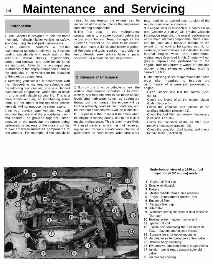
Underbonnet view of a 1360 cc fuelinjection (KDY engine) model
1 Engine oil filler cap2 Engine oil dipstick3 Battery4 Master cylinder brake fluid reservoir5 Engine compartment junction box6 Engine oil filter7 Radiator filler cap8 Alternator9 Windscreen/tailgate washer fluid reservoir
filler cap10 Braking system vacuum servo unit11 Ignition HT coil12 Plastic box containing the fuel injection
ECU, relay unit and injector resistor13 Suspension strut upper mounting14 Air cleaner air temperature control valve15 Throttle body assembly16 Evaporative emission control purge valves17 Ignition timing retard system solenoid
valve18 Air cleaner housing
1•4
1 Introduction
2 Intensive maintenance

Maintenance and Servicing
Underbonnet view of a 1580 cc(BDY engine) model
1 Engine oil filler cap2 Engine oil dipstick3 Battery4 Master cylinder brake fluid reservoir5 Engine compartment junction box6 Engine oil filter7 Radiator filler cap8 Alternator9 Windscreen/tailgate washer fluid reservoir
filler cap10 Braking system vacuum servo unit11 Ignition HT coil12 Plastic box containing the fuel injection
ECU and relay unit13 Suspension strut upper mounting14 Air cleaner air temperature control valve15 Throttle body assembly16 Fuel injection system MAP sensor17 Thermostat housing18 Air cleaner housing
Underbonnet view of a 1761 cc(LFZ engine) model
1 Engine oil filler cap2 Engine oil dipstick3 Battery4 Master cylinder brake fluid reservoir5 Engine compartment junction box6 Engine oil filter7 Radiator filler cap8 Alternator9 Windscreen/tailgate washer fluid reservoir
filler cap10 Braking system vacuum servo unit11 Ignition HT coil12 Plastic box containing the fuel injection
ECU13 Suspension strut upper mounting14 Fuel injection system relay unit15 Throttle housing assembly16 Fuel injection system MAP sensor17 Idle speed auxiliary air valve18 Air cleaner element cover
1•5
Maintenance and Servicing
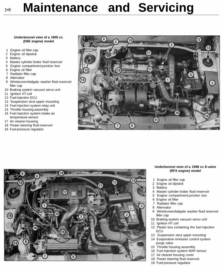
Underbonnet view of a 1905 cc(D6E engine) model
1 Engine oil filler cap2 Engine oil dipstick3 Battery4 Master cylinder brake fluid reservoir5 Engine compartment junction box6 Engine oil filter7 Radiator filler cap8 Alternator9 Windscreen/tailgate washer fluid reservoir
filler cap10 Braking system vacuum servo unit11 Ignition HT coil12 Fuel injection ECU13 Suspension strut upper mounting14 Fuel injection system relay unit15 Throttle housing assembly16 Fuel injection system intake air
temperature sensor17 Air cleaner housing18 Power steering fluid reservoir19 Fuel pressure regulator
Underbonnet view of a 1998 cc 8-valve(RFX engine) model
1 Engine oil filler cap2 Engine oil dipstick3 Battery4 Master cylinder brake fluid reservoir5 Engine compartment junction box6 Engine oil filter7 Radiator filler cap8 Alternator9 Windscreen/tailgate washer fluid reservoir
filler cap10 Braking system vacuum servo unit11 Ignition HT coil12 Plastic box containing the fuel injection
ECU13 Suspension strut upper mounting14 Evaporative emission control system
purge valve15 Throttle housing assembly16 Fuel injection system MAP sensor17 Air cleaner housing cover18 Power steering fluid reservoir19 Fuel pressure regulator
1•6

Maintenance and Servicing
Front underbody view - 1998 cc 16-valvemodel shown (other models similar)
1 Wiring harness2 Power steering pump3 Sump drain plug4 Oil filter5 Power steering fluid hose6 Air filter housing7 Towing eye8 Horn9 Horn compressor
10 Brake caliper11 Lower suspension arm12 Track rod balljoint13 Anti-roll bar14 Transmission oil drain plug15 Steering gear assembly16 Front suspension subframe17 Driveshaft18 Engine/transmission rear mounting
Rear underbody view - rear disc brakemodel shown (drum brake models similar)
1 Fuel tank2 Fuel tank support bracket3 Handbrake cables4 Rear suspension torsion bars5 Rear suspension tubular crossmember6 Exhaust heat shield7 Rear shock absorber8 Rear suspension trailing arm9 Brake caliper
10 Rear exhaust box11 Spare wheel cradle retaining catch12 Jack case13 Rear brake pressure-regulating valves
1•7

Weekly ChecksWeekly checks3 Fluid level checks
Engine oil1 The engine oil level is checked with adipstick. This extends through the dipsticktube, into the sump at the bottom of theengine. On 1124 cc, 1360 cc and 1998 cc8-valve models, the dipstick is located at thefront of the engine. On all other models, thedipstick is located at the rear of the engine.The dipstick top is brightly-coloured (usuallyorange) for easy identification.2 The oil level should be checked with thevehicle standing on level ground. Check thelevel before the engine is started, or wait atleast 5 minutes after the engine has beenswitched off.
3 Withdraw the dipstick from the tube, andwipe all the oil from the end with a clean rag orpaper towel. Insert the clean dipstick backinto the tube as far as it will go, then withdraw
3.3 Engine oil level dipstick markings
it once more. Note the oil level on the end ofthe dipstick. Add oil as necessary until thelevel is between the upper ("MAX") mark andlower ("MIN") mark on the dipstick (seeillustration). Approximately 1.5 litres of oil willbe required to raise the level from the lowermark to the upper mark, on models without airconditioning. The amount is 1.3 litres onmodels with air conditioning.4 Always maintain the level between the twodipstick marks. If the level is allowed to fallbelow the lower mark, oil starvation mayresult, which could lead to severe enginedamage. If the engine is overfilled by addingtoo much oil, this may result in oil leaks or oilseal failures.5 Oil is added to the engine either via the fillercap on the cylinder head cover (1124 cc,1360 cc, 1761 cc and 1998 cc 8-valve models)or via the filler/breather cap (1580 cc, 1905 ccand 1998 cc 16-valve models). Unscrew thecap and top-up the level - an oil can spout orfunnel may help to reduce spillage. Always usethe correct grade and type of oil, as shown in"Lubricants, fluids and capacities".
CoolantWarning: DO NOT attempt toremove the expansion tankpressure cap when the engine ishot, as there is a very great riskof scalding.
6 All vehicles covered by this manual are
3.7 Coolant expansion tank level markings
equipped with a pressurised cooling system.An expansion tank is incorporated in the right-hand side of the radiator. As the enginetemperature increases, the coolant expands,and the level in the expansion tank rises. Asthe engine cools, the coolant is automaticallydrawn back into the system, to maintain thecorrect level.7 The coolant level in the expansion tankshould be checked regularly. The level in thetank varies with the temperature of the engine.When the engine is cold, the coolant levelshould be between the "MIN" and "MAX"marks on the side of the tank. When theengine is hot, the level may rise slightly abovethe "MAX" mark (see illustration).8 If topping-up is necessary, wait until theengine is cold, then turn the pressure cap onthe expansion tank anti-clockwise until itreaches the first stop. Wait until any pressureremaining in the system is released, then pushthe cap down, turn it anti-clockwise to thesecond stop, and lift it off.9 Add a mixture of water and antifreeze (seeSection 31) through the expansion tank fillerneck, until the coolant is approximatelyhalfway between the two level marks (seeillustration). Refit the cap, turning itclockwise as far as it will go to secure.10 With a "sealed" cooling system such asthis, the addition of coolant should only benecessary at very infrequent intervals. Iffrequent topping-up is required, it is likely thereis a leak in the system. Check the radiator, andall hoses and joint faces, for any sign of stainingor actual wetness, and rectify as necessary. Ifno leaks can be found, it is advisable to havethe pressure cap (and the entire system)pressure-tested by a dealer or suitably-equipped garage. This will often show up smallleaks which were not previously visible.
Brake fluid11 The brake master cylinder and fluidreservoir assembly is mounted on the front ofthe vacuum servo unit in the enginecompartment. The maximum and minimummarks are indicated on the side of thereservoir (see illustration). The fluid level
3.9 Topping-up the coolant level 3.11 Brake fluid reservoir level markings 3.12 Topping-up the brake fluid level
1•8
If the oil is checkedimmediately after switchingoff the engine, some of the oilwill remain in the upper
engine components and oil galleries,resulting in an inaccurate reading onthe dipstick.

Weekly Checksshould be maintained between these marks atail times.12 If topping-up is necessary, first wipe thearea around the "filier cap with a clean ragbefore removing the cap. When adding fluid,pour it carefully into the reservoir, to avoidspilling it on surrounding painted surfaces(see illustration). Be sure to use only thespecified brake hydraulic fluid, since mixingdifferent types of fluid can cause damage tothe system. Refer to "Lubricants fluids andcapacities" at the beginning of this Chapter.
Warning: Brake hydraulic fluidcan harm your eyes, and willdamage painted surfaces, souse extreme caution when
handling and pouring it. It is also highly-inflammable. Do not use fluid that hasbeen standing open for some time, as itabsorbs moisture from the air. Excessmoisture in the fluid can cause adangerous loss of braking effectiveness.13 When adding fluid, it is a good idea toinspect the reservoir for contamination. Thesystem should be drained and refilled ifdeposits, dirt particles or contamination areseen in the fluid.14 After filling the reservoir to the correctlevel, make sure that the cap is refittedsecurely, to avoid leaks and the entry offoreign matter.15 The fluid level in the master cylinderreservoir will drop slowly as the brake padsand shoes wear down during normaloperation. Provided that the level does notdrop below the minimum mark, there is noneed to top up to compensate for this fall. Thelevel will rise again when new brake pads orlinings are fitted. If the reservoir requiresrepeated replenishing to maintain the properlevel, this is an indication of a hydraulic leaksomewhere in the system, which should beinvestigated immediately.
Power steering fluid16 The power steering fluid reservoir islocated on the right-hand side of the enginecompartment.17 For the check, the car should be parkedon level ground, with the front wheels pointingstraight-ahead. The engine should be
switched off. For the check to be accurate,the steering must not be turned once theengine has been stopped.18 The fluid level is visible in the reservoir,and should be between the "MAX" and "MIN"level lines cast on the side of the reservoir(see illustration).19 If topping-up is necessary, wipe the areaaround the reservoir cap clean, then unscrewthe cap. Top-up to the "MAX" mark using thespecified type of fluid (see illustration). Takegreat care not to allow any dirt or foreign matterto enter the hydraulic system, and do notoverfill the reservoir. When the level is correct,refit the cap. Note that the need for frequenttopping-up of the system indicates a leak,which should be investigated immediately.
Washer fluid20 The windscreen/tailgate washer fluidreservoir filler is located at the rear right-handcorner of the engine compartment, behind thesuspension strut (see illustration).21 On models fitted with a headlight washersystem, an additional reservoir is locatedunder the front right-hand wing. To top-up thereservoir, turn and extend the filler neck whichprotrudes into engine compartment.22 When topping-up the reservoir(s), ascreenwash additive should be added, in itsmanufacturer's recommended quantities. Theadditive used in winter must give protectionagainst freezing. Do not use engine antifreezein the screen washer reservoir; it will damagethe wiper blades and the paintwork.
4 Tyre checks
1 The original tyres on this car are equippedwith tread wear safety bands, which willappear when the tread depth reachesapproximately 1.6 mm. Tread wear can bemonitored with a simple, inexpensive deviceknown as a tread depth indicator gauge (seeillustration).2 Wheels and tyres should give no realproblems in use, provided that a close eye iskept on them with regard to excessive wear ordamage. To this end, the following pointsshould be noted.3 Ensure that the tyre pressures are checkedregularly and maintained correctly. Checkingshould be carried out with the tyres cold, andnot immediately after the vehicle has been inuse (see illustration). If the pressures arechecked with the tyres hot, an apparently-high reading will be obtained, owing to heatexpansion. Under no circumstances should anattempt be made to reduce the pressures tothe quoted cold reading in this instance, oreffective under-inflation will result.4 Note any abnormal tread wear (seeillustration). Tread pattern irregularities suchas feathering, flat spots, and more wear onone side than the other, are indications offront wheel alignment and/or balanceproblems. If any of these conditions arenoted, they should be rectified as soon aspossible.
3.18 Power steering fluid reservoirmarkings
3.19 Topping-up the power steering fluidlevel
3.20 Topping-up the washer fluid level 4.1 Checking a tyre tread depth with adepth gauge
4.3 Checking a tyre pressure with a tyrepressure gauge
1•9

Weekly ChecksTyre Tread Wear Patterns
Shoulder WearUnderinflation(wear on both sides)Check and adjust pressures
Incorrect wheel camber(wear on one side)Repair or renew suspensionparts
Hard corneringReduce speed!
Centre Wear Toe Wear Uneven Wear
OverinflationCheck and adjust pressures
If you sometimes have to inflateyour car's tyres to the higherpressures specified for maximumload or sustained high speed,don't forget to reduce the pres-sures to normal afterwards.
Incorrect toe settingAdjust front wheel alignment
Note: The feathered edge ofthe tread which characterises
toe wear is best checked byfeel.
Incorrect camber or castorRepair or renew suspensionparts
Malfunctioning suspensionRepair or renew suspensionparts
Unbalanced wheelBalance tyres
Qut-of-round brake disc/drumMachine or renew
5 Under-inflation will cause overheating of thetyre, owing to excessive flexing of the casing,and the tread will not sit correctly on the roadsurface. This will cause a consequent loss ofadhesion and excessive wear, not to mentionthe danger of sudden tyre failure due to heatbuild-up.6 Over-inflation will cause rapid wear of thecentre part of the tyre tread, coupled withreduced adhesion, harsher ride, and thedanger of shock damage occurring in the tyrecasing.7 Regularly check the tyres for damage in theform of cuts or bulges, especially in thesidewalls. Remove any nails or stonesembedded in the tread, before they penetratethe tyre to cause deflation. If a nail isremoved, revealing that the tyre has beenpunctured, refit the nail so that its point ofpenetration is clearly marked. Change thewheel immediately, and have the tyre repairedby a tyre dealer. Do not drive on a tyre in sucha condition. If in any doubt as to the possibleconsequences of any damage found, consultyour local tyre dealer for advice.8 Periodically remove the wheels, and cleanany dirt or mud from the inside and outsidesurfaces. Examine the wheel rims for signs ofrusting, corrosion or other damage. Light alloywheels are easily damaged by "kerbing"whilst parking, and similarly, steel wheels maybecome dented or buckled. Renewal of the
wheel is very often the only course of remedialaction possible.9 The balance of each wheel and tyreassembly should be maintained, to avoidexcessive wear, not only to the tyres, but alsoto the steering and suspension components.Wheel imbalance is normally signified byvibration through the vehicle's bodyshell,although in many cases it is particularlynoticeable through the steering wheel.Conversely, it should be noted that wear ordamage in suspension or steeringcomponents may cause excessive tyre wear.Out-of-round or out-of-true tyres, damagedwheels, and worn wheel bearings also fall intothis category. Balancing alone will not usuallycure vibration caused by such wear.10 Wheel balancing may be carried out withthe wheel either on or off the vehicle. Ifbalanced on the vehicle, ensure that thewheel-to-hub relationship is marked in someway prior to subsequent wheel removal, sothat it may be refitted in its original position.11 General tyre wear is influenced to a largedegree by driving style - harsh braking andacceleration, or fast cornering, will all producemore rapid tyre wear. Interchanging of tyresmay result in more even wear. However, it isworth bearing in mind that if this is completelyeffective, the added expense is incurred ofrenewing four tyres at once, which may provefinancially restrictive for many owners.
12 Front tyres may wear unevenly as a resultof wheel misalignment. The front wheelsshould always be correctly aligned accordingto the settings specified by the vehiclemanufacturer.13 Legal restrictions apply to many aspectsof tyre fitting and usage. In the UK, thisinformation is contained in the Motor VehicleConstruction and Use Regulations. It issuggested that a copy of these regulations isobtained from your local police, if you are indoubt as to current legal requirements withregard to tyre type and condition, minimumtread depth, etc.
5 Electrical system check
1 Check the operation of all the electricalequipment (lights, direction indicators, horn,etc). Refer to the appropriate Sections ofChapter 12 for details if any of the circuits arefound to be inoperative.2 Note that stop-light switch adjustment isdescribed in Chapter 9.3 Visually check all accessible wiringconnectors, harnesses and retaining clips forsecurity, and for signs of chafing or damage.Rectify any faults found.
1•10

Every 6000 miles6 Battery check
Caution: Before carrying out anywork on the vehicle battery, readthrough the precautions given in"Safety first!" at the beginning ofthis manual.
1 The battery is located on the left-hand sideof the engine compartment. The exterior ofthe battery should be inspected periodicallyfor damage such as a cracked case or cover.2 Check the tightness of the battery cableclamps, to ensure good electricalconnections. Check the entire length of eachcable for cracks and fraying.3 If corrosion (visible as white, fluffy deposits) isevident, remove the cables from the batteryterminals, clean them with a small wire brush,then refit them. It is advisable to wear gloves and
eye protection when removing these deposits.Further corrosion can be kept to a minimum byapplying a layer of petroleum jelly to the clampsand terminals after they are reconnected.4 Make sure that the battery tray is in goodcondition, and that the retaining clamp istight.5 Corrosion on the tray, retaining clamp, orthe battery itself, can be removed with asolution of water and baking soda. Again,wear gloves and eye protection. Thoroughlyrinse all cleaned areas with plain water.6 Any metal parts of the vehicle damaged bycorrosion should be covered with a zinc-based primer, then painted.7 Periodically (approximately every threemonths), check the state of charge of thebattery, as described in Chapter 5.8 Further information on the battery, chargingand jump-starting can be found in Chapter 5,and in the preliminary sections of this manual.
Every 6000 miles or 6 months
Note: The manufacturer specifies that the oilfilter should be renewed at the first 6000-mileor 6-month service. After that, the recommen-dation is for filter renewal at 12 000 miles or12-monthly intervals, with only the oil beingdrained and renewed every 6000 miles or6 months. Owners of high-mileage vehicles, orthose who do a lot of stop-start driving, mayprefer to carry out filter renewal at the6000-mile or 6-month interval as aprecautionary task.
1 Frequent oil and filter changes are the mostimportant preventative maintenanceprocedures which can be undertaken by theDIY owner. As engine oil ages, it becomesdiluted and contaminated, which leads topremature engine wear.2 Before starting this procedure, gathertogether all the necessary tools and materials.Also make sure that you have plenty of cleanrags and newspapers handy, to mop up anyspills. Ideally, the engine oil should be warm,
as it will drain better, and more built-upsludge will be removed with it. Take care,however, not to touch the exhaust or anyother hot parts of the engine when workingunder the vehicle. To avoid any possibility ofscalding, it is advisable to wear gloves whencarrying out this work. This will also protectyou from possible skin irritants and otherharmful contaminants in used engine oils.Access to the underside of the vehicle will begreatly improved if it can be raised on a lift,driven onto ramps, or jacked up andsupported on axle stands (see "Jacking,towing and wheel changing"). Whichevermethod is chosen, make sure that the vehicleremains level; if it is at an angle, make surethat the oil will flow towards the drain plug.3 Using a suitable key (typically 8 mmsquare), slacken the drain plug about half aturn (see illustration). Position a suitablecontainer under the drain plug, then removethe plug completely. If possible, try to keepthe plug pressed into the sump whileunscrewing it by hand the last couple of turns.As the plug releases from the threads, move itaway sharply, so the stream of oil issuing fromthe sump runs into the container, not up your
7 Wiper blade check
1 Check the condition of the wiper blades. Ifthey are cracked, or show any signs ofdeterioration, or if the glass swept area issmeared, renew them.
2 To remove a wiper blade, pull the arm fullyaway from the glass until it locks. Swivel theblade through 90°, press the locking tab(s)with your fingers, and slide the blade out ofthe arm's hooked end. On refitting, ensurethat the blade locks securely into the arm.
sleeve! Recover the sealing ring from the drainplug.4 Allow some time for the old oil to drain,noting that it may be necessary to repositionthe container as the oil flow slows to a trickle.5 After all the oil has drained, wipe off thedrain plug with a clean rag, and renew thesealing washer. Clean the area around thedrain plug opening, and refit the plug. Tightenthe plug securely.6 If the filter is also to be renewed, move thecontainer into position under the oil filter,which is located on the front side of thecylinder block, below the inlet manifold.7 Using an oil filter removal tool, slacken thefilter initially, then unscrew it by hand the restof the way (see illustration). Empty the oil inthe old filter into the container.8 Use a clean rag to remove all oil, dirt andsludge from the filter sealing area on theengine. Check the old filter to make sure thatthe rubber sealing ring hasn't stuck to theengine. If it has, carefully remove it.9 Apply a light coating of clean engine oil tothe sealing ring on the new filter, then screw itinto position on the engine (see illustration).Tighten the filter firmly by hand only - do not
8.3 Slackening the sump drain plug(1905 cc model shown)
8.7 Using an oil filter removal tool toslacken the oil filter (1360 cc model shown)
8.9 Lubricate the oil filter sealing ringbefore fitting
1•11
8 Engine oil and filter renewal
For maximum clarity of vision,wiper blades should berenewed annually, as a matterof course.

Every 6000 milesuse any tools. Follow the tighteninginstructions printed on the filter, if applicable.10 Remove the old oil and all tools fromunder the car, then (if applicable) lower the carto the ground.11 Remove the dipstick, then unscrew the oilfiller cap from the filler/breather neck orcylinder head cover (as applicable). Fill theengine, using the correct grade and type of oil(refer to "Lubricants fluids and capacities"). Anoil can spout or funnel may help to reducespillage. Pour in half the specified quantity ofoil first, then wait a few minutes for the oil torun down to the sump. Continue adding oil, asmall quantity at a time, until the level is up tothe lower mark on the dipstick. Adding afurther 1.5 litres (models without airconditioning) or 1.3 litres (models with airconditioning), will bring the level up to theupper mark on the dipstick. Refit the filler cap.12 Start the engine, and run it for a fewminutes, checking for leaks around the oilfilter seal and the sump drain plug. Note thatthere may be a delay of a few seconds beforethe low oil pressure warning light goes outwhen the engine is first started. The oil takestime to circulate through the new oil filter andthe engine oil galleries before the pressurebuilds up. Do not rev the engine while thewarning light is on.13 Switch off the engine, and wait a fewminutes for the oil to settle in the sump oncemore. With the new oil circulated and the filternow completely full, recheck the level on thedipstick, and add more oil as necessary.14 Dispose of the used engine oil and filtersafely, with reference to "General repairprocedures" in the reference Sections of thismanual.
Note: It isantisocial andillegal to dumpoil down thedrain. To findthe location ofyour local oilrecyclingbank, call thisnumber free.0800 66 33 66
9 Hose and fluid leak check
1 Visually inspect the engine joint faces,gaskets and seals for any signs of water, oil orfuel leaks. Pay particular attention to the areasaround the camshaft cover, cylinder head, oilfilter and sump joint faces. Bear in mind that,over a period of time, some very slightseepage from these areas is to be expected.What you are really looking for is anyindication of a serious leak. Should a leak befound, renew the offending gasket or oil sealby referring to the appropriate Chapters in thismanual.
2 Also check the security and condition of allthe engine-related pipes and hoses. Ensurethat all cable ties or securing clips are in placeand in good condition. Clips which are brokenor missing can lead to chafing of the hoses,pipes, or wiring, which could cause moreserious problems in the future.3 Carefully check the radiator hoses andheater hoses along their entire length. Renewany hose which is cracked, swollen, ordeteriorated. Cracks will show up better if thehose is squeezed. Pay close attention to thehose clips that secure the hoses to the coolingsystem components. Hose clips can pinch andpuncture hoses, resulting in cooling systemleaks. If the original Citroen crimped-type hoseclips are used, it may be a good idea to replacethem with standard worm-drive hose clips.4 Inspect all the cooling system components(hoses, joint faces, etc.) for leaks. A leak in thecooling system will usually show up as whiteor rust-coloured deposits on the areaadjoining the leak. Where any problems of thisnature are found on system components,renew the component or gasket withreference to Chapter 3.5 Where applicable, inspect the automatictransmission fluid cooler hoses for leaks ordeterioration.6 With the vehicle raised, inspect the petroltank and filler neck for punctures, cracks, andother damage. The connection between thefiller neck and tank is especially critical.Sometimes, a rubber filler neck or connectinghose will leak due to loose retaining clamps ordeteriorated rubber.7 Carefully check all rubber hoses and metalfuel lines leading away from the petrol tank.Check for loose connections, deterioratedhoses, crimped lines, and other damage. Payparticular attention to the vent pipes andhoses, which often loop up around the fillerneck, and can become blocked or crimped.Follow the lines to the front of the vehicle,carefully inspecting them all the way. Renewdamaged sections as necessary.8 From within the engine compartment,check the security of all fuel hose attachmentsand pipe unions, and inspect the fuel hosesand vacuum hoses for kinks, chafing anddeterioration.
1 Take the vehicle on a short journey, towarm the transmission up to normal operatingtemperature, then park the vehicle on levelground. The fluid level is checked using thedipstick located at the front of the enginecompartment, directly in front of theengine/transmission. The dipstick top isbrightly-coloured (usually orange) for easyidentification.2 With the engine idling and the selector leverin the "P" (Park) position, withdraw thedipstick from the tube, and wipe all the fluidfrom its end with a clean rag or paper towel.Insert the clean dipstick back into the tube asfar as it will go, then withdraw it once more.Note the fluid level on the end of the dipstick;it should be between the upper and lowermarks (see illustration).3 If topping-up is necessary, add the requiredquantity of the specified fluid to thetransmission via the dipstick tube. Note:A/ever overfill the transmission so that the fluidlevel is above the upper mark.
4 After topping-up, take the vehicle on ashort run to distribute the fresh fluid, thenrecheck the level again, topping-up ifnecessary.5 Always maintain the level between the twodipstick marks. If the level is allowed to fallbelow the lower mark, fluid starvation mayresult, which could lead to severetransmission damage.6 Frequent need for topping-up indicates thatthere is a leak, which should be found andcorrected before it becomes serious.
11 Steering and suspensioncheck
10.2 Automatic transmission fluid dipsticklower (a) and upper (b) fluid level markings
Front suspension and steeringcheck1 Raise the front of the vehicle, and securelysupport it on axle stands.2 Visually inspect the balljoint dust coversand the steering rack-and-pinion gaiters forsplits, chafing or deterioration (seeillustration). Any wear of these componentswill cause loss of lubricant, together with dirtand water entry, resulting in rapiddeterioration of the balljoints or steering gear.3 On vehicles with power steering, check thefluid hoses for chafing or deterioration, andthe pipe and hose unions for fluid leaks. Also
1•12
10 Automatic transmissionfluid level check
9 Where applicable, check the condition ofthe power steering fluid hoses and pipes.
Use a funnel with a fine meshgauze to avoid fluid spillage,and to ensure that no foreignmatter enters thetransmission

Every 6000 miles
11.2 Checking a steering gear gaiter
check for signs of fluid leakage underpressure from the steering gear rubbergaiters, which would indicate failed fluid sealswithin the steering gear.4 Grasp the roadwheel at the 12 o'clock and6 o'clock positions, and try to rock it (seeillustration). Very slight free play may be felt,but if the movement is appreciable, furtherinvestigation is necessary to determine thesource. Continue rocking the wheel while anassistant depresses the footbrake. If themovement is now eliminated or significantlyreduced, it is likely that the hub bearings areat fault. If the free play is still evident with thefootbrake depressed, then there is wear in thesuspension joints or mountings.5 Now grasp the wheel at the 9 o'clock and3 o'clock positions, and try to rock it as before.Any movement felt now may again be causedby wear in the hub bearings or the steeringtrack-rod balljoints. If the outer balljoint isworn, the visual movement will be obvious. Ifthe inner joint is suspect, it can be felt byplacing a hand over the rack-and-pinionrubber gaiter and gripping the track-rod. If thewheel is now rocked, movement will be felt atthe inner joint if wear has taken place.6 Using a large screwdriver or flat bar, checkfor wear in the suspension mounting bushes bylevering between the relevant suspensioncomponent and its attachment point. Somemovement is to be expected, as the mountingsare made of rubber, but excessive wear shouldbe obvious. Also check the condition of anyvisible rubber bushes, looking for splits, cracksor contamination of the rubber.7 With the car standing on its wheels, have anassistant turn the steering wheel back andforth, about an eighth of a turn each way.There should be very little, if any, lostmovement between the steering wheel androadwheels. If this is not the case, closelyobserve the joints and mountings previouslydescribed. In addition, check the steeringcolumn universal joints for wear, and alsocheck the rack-and-pinion steering gear itself.
11.4 Rocking the roadwheel to checksteering/suspension components
Suspension strut/shock absorbercheck8 Check for any signs of fluid leakage aroundthe suspension strut/shock absorber body, orfrom the rubber gaiter around the piston rod.Should any fluid be noticed, the suspensionstrut/shock absorber is defective internally,and should be renewed. Note: Suspensionstruts/shock absorbers should always berenewed in pairs on the same axle.9 The efficiency of the suspensionstrut/shock absorber may be checked bybouncing the vehicle at each corner.Generally speaking, the body will return to itsnormal position and stop after beingdepressed. If it rises and returns on arebound, the suspension strut/shockabsorber is probably suspect. Examine alsothe suspension strut/shock absorber upperand lower mountings for any signs of wear.
12 Drivesshaft gaiter check
Driveshaft rubber gaiter and CVjoint check1 With the vehicle raised and securelysupported on stands, turn the steering ontofull lock, then slowly rotate the roadwheel.Inspect the condition of the outer constantvelocity (CV) joint rubber gaiters, whilesqueezing the gaiters to open out the folds(see illustration). Check for signs of cracking,splits, or deterioration of the rubber, whichmay allow the grease to escape, and lead towater and grit entry into the joint. Also checkthe security and condition of the retainingclips. Repeat these checks on the inner CVjoints. If any damage or deterioration is found,the gaiters should be renewed without delayas described in Chapter 8.2 At the same time, check the generalcondition of the CV joints themselves, by first
12.1 Checking driveshaft outer constantvelocity (CV) joint gaiter
13.2 Front brake friction material can bechecked through slot in caliper body -
Girling caliper shown
holding the driveshaft and attempting torotate the wheel. Repeat this check by holdingthe inner joint and attempting to rotate thedriveshaft. Any appreciable movementindicates wear in the joints, wear in thedriveshaft splines, or a loose driveshaftretaining nut.
13 Front brake pad conditioncheck
1 Firmly apply the handbrake, then jack upthe front of the car and support it securely onaxle stands. Remove the front roadwheels.2 For a quick check, the thickness of frictionmaterial remaining on each brake pad can bemeasured through the slot in the caliper body(see illustration). If any pad's friction materialis worn to the specified minimum thickness orless, all four pads must be renewed as a set.3 For a comprehensive check, the brake padsshould be removed and cleaned. This willpermit the operation of the caliper to bechecked, and the condition of the brake discitself to be fully examined on both sides. Referto Chapter 9 for further information.
1•13

Every 12 000 milesEvery 12 000 miles or 12 months14 Air conditioning system
refrigerant check
Warning: Do not attempt to openthe refrigerant circuit. Refer to theprecautions given in Chapter 3.
1 In order to check the condition of therefrigerant, a humidity indicator and a sightglass are provided on top of the drier bottle,which is located at the front right-hand cornerof the engine compartment.
Refrigerant humidity check2 Check the colour of the humidity indicator(see illustration). Blue indicates that thecondition of the refrigerant is satisfactory. Redindicates that the refrigerant is saturated withhumidity. If the indicator shows red, thesystem should be drained and recharged, anda new drier bottle should be fitted. Note: Thesystem should be drained and recharged onlyby a Citroen dealer or air conditioningspecialist. Do not attempt to carry out thework yourself.
Refrigerant flow check3 Run the engine, and switch on the airconditioning.4 After a few minutes, inspect the sight glass,and check the fluid flow. Clear fluid should bevisible - if not, the following will help todiagnose the problem:(a) Clear fluid flow, perhaps with occasional
bubbles - the system is functioningcorrectly.
(b) No fluid flow - have the system checkedfor leaks by a Citroen dealer or airconditioning specialist.
(c) Continuous stream of clear air bubbles influid - refrigerant level low. Have thesystem recharged by a Citroen dealer orair-conditioning specialist.
(d) Milky air bubbles visible - high humidity(see paragraph 2).
5 Do not operate the air conditioning systemif the refrigerant level is known to be low;damage may result.
15 Valve clearance check andadjustment -1124 cc and 1360 cc models
Note: The valve clearances must be checkedand adjusted only when the engine is cold.Note: The manufacturer suggests this operationat the first 12 000 mile service only. After that,checking and adjusting of the valve clearancesis not part of the recommended maintenanceschedule. The operation should therefore onlyneed to be carried out after engine overhaul, orwhen investigating noise or power loss whichcould be attributed to the valve gear.1 The importance of having the valveclearances correctly adjusted cannot beoverstressed, as they vitally affect theperformance of the engine. If the clearancesare too big, the engine will be noisy(characteristic rattling or tapping noises) andengine efficiency will be reduced, as thevalves open too late and close too early. Amore serious problem arises if the clearancesare too small, however. If this is the case, thevalves may not close fully when the engine ishot, resulting in serious damage to the engine(eg. burnt valve seats and/or cylinder headwarping/cracking). The clearances arechecked and adjusted as follows.2 Remove the cylinder head cover asdescribed in Chapter 2A.3 The engine can now be turned using asuitable socket and extension bar fitted to thecrankshaft sprocket/pulley bolt.
4 It is important that the clearance of eachvalve is checked and adjusted only when thevalve is fully closed, with the rocker arm restingon the heel of the cam (directly opposite thepeak). This can be ensured by carrying out theadjustments in the following sequence, notingthat No 1 cylinder is at the transmission end of
the engine. The correct valve clearances aregiven in the Specifications at the end of thisChapter. The valve locations can bedetermined from the position of the manifolds.
Valve fullyopen Adjust valvesNo 1 exhaust No 3 inlet and No 4 exhaustNo 3 exhaust No 4 inlet and No 2 exhaustNo 4 exhaust No 2 inlet and No 1 exhaustNo 2 exhaust No 1 inlet and No 3 exhaust
5 With the relevant valve fully open, check theclearances of the two valves specified.Clearances are checked by inserting a feelergauge of the correct thickness between thevalve stem and the rocker arm adjusting screw.The feeler gauge should be a light, sliding fit. Ifadjustment is necessary, slacken the adjustingscrew locknut, and turn the screw as necessary.Once the correct clearance is obtained, hold theadjusting screw and securely tighten the locknut(see illustration). Recheck the valve clearance,and adjust again if necessary.6 Rotate the crankshaft until the next valve inthe sequence is fully open, and check theclearances of the next two specified valves.7 Repeat the procedure until all eight valveclearances have been checked (and ifnecessary, adjusted), then refit the cylinderhead cover as described in Chapter 2A.
16 Spark plug renewal
1 The correct functioning of the spark plugs isvital for the correct running and efficiency ofthe engine. It is essential that the plugs fittedare appropriate for the engine (the suitable typeis specified at the end of this Chapter). If thistype is used, and the engine is in goodcondition, the spark plugs should not needattention between scheduled replacementintervals. Spark plug cleaning is rarelynecessary, and should not be attempted unlessspecialised equipment is available, as damagecan easily be caused to the firing ends.2 On 1998 cc 16-valve models, to gainaccess to the spark plugs, the access cover
14.2 Air conditioning system refrigeranthumidity indicator (A) and sight glass (B)
15.5 Adjusting a valve clearance -1124 ccand 1360 cc models
16.2 On 1998 cc 16-valve models, undothe eight bolts (arrowed) and remove the
access cover to reach the spark plugs
1•14
Turning the engine will beeasier if the spark plugs areremoved.

Every 12 000 miles
16.7 Tools required for spark plugremoval, gap adjustment and refitting
fitted in the centre of the cylinder head covermust first be removed. Undo the eight bolts,noting the position of the wiring retaining clip,and remove the cover (see illustration).3 On some other models, to improve accessto some of the plugs, it may be necessary toremove the air intake duct (refer to Chapter 4for further information).4 On 1998 cc 16-valve models, pull the HTcoils off the spark plugs. If necessary, toremove the possibility of the HT coils beingconnected to the wrong spark plugs onrefitting, mark the coils 1 to 4 (No 1 cylinder isat the transmission end of the engine).5 On all other models, if the marks on theoriginal-equipment spark plug (HT) leadscannot be seen, mark the leads 1 to 4,corresponding to the cylinder the lead serves(No 1 cylinder is at the transmission end of theengine). Pull the leads from the plugs bygripping the end fitting, not the lead, otherwisethe lead connection may be fractured.6 It is advisable to remove the dirt from thespark plug recesses, using a clean brush,vacuum cleaner or compressed air beforeremoving the plugs, to prevent dirt droppinginto the cylinders.7 Unscrew the plugs using a spark plugspanner, suitable box spanner, or a deepsocket and extension bar (see illustration).Keep the socket aligned with the spark plug -if it is forcibly moved to one side, the ceramicinsulator may be broken off. As each plug isremoved, examine it as follows.8 Examination of the spark plugs will give agood indication of the condition of the engine.If the insulator nose of the spark plug is cleanand white, with no deposits, this is indicativeof a weak mixture. It could also indicate thatthe plug is too "hot" for the engine (a hot plugtransfers heat away from the electrode slowly,a cold plug transfers heat away quickly). If thiscondition is apparent, either correct themixture setting (where possible), or ensurethat the correct grade of plug is fitted.9 If the tip and insulator nose are coveredwith hard black-looking deposits, then this isindicative that the mixture is too rich. Shouldthe plug be black and oily, then it is likely thatthe engine is fairly worn, as well as the mixturebeing too rich.
16.12 Measuring the spark plug gap with afeeler gauge
10 If the insulator nose is covered with lighttan to greyish-brown deposits, then themixture is correct, and it is likely that theengine is in good condition.11 The spark plug electrode gap is ofconsiderable importance as, if it is too large ortoo small, the size of the spark and itsefficiency will be seriously impaired. The gapshould be set to the value given in theSpecifications at the end of this Chapter.12 To set it, measure the gap with a feelergauge. If necessary, bend the outer plugelectrode open or closed until the correct gapis achieved (see illustration). The centreelectrode should never be bent, as this maycrack the insulator and cause plug failure, ifnothing worse.13 Special spark plug electrode gapadjusting tools are available from most motoraccessory shops (see illustrations).14 Before fitting the spark plugs, check thatthe threaded connector sleeves (on top of theplug) are tight, and that the plug exteriorsurfaces and threads are clean. Apply a smearof copper-based anti-seize compound to theplug threads.15 It is very often difficult to insert sparkplugs into their holes without cross-threadingthem. To avoid this possibility, fit a shortlength of 5/16 inch/8 mm internal diameterrubber or plastic hose over the end of thespark plug. (Flexible fuel hose is ideal.) Theflexible hose acts as a universal joint to helpalign the plug with the plug hole. Should theplug begin to cross-thread, the hose will slipon the spark plug, preventing thread damageto the aluminium cylinder head. Once the plugbegins to screw in correctly, remove the hose,and tighten the plug to the specified torqueusing the spark plug socket and a torquewrench. Refit the remaining spark plugs in thesame manner.
16 On 1998 cc 16-valve models, connect theHT coils in their correct order, then refit theaccess cover to the cylinder head cover. Ensurethat the coil wiring is correctly located in thecover recess. Refit the cover bolts, not forgettingthe wiring clip, and tighten them securely.17 On all other models, connect the HT leadsin their correct order, and refit anycomponents removed for access.
16.13a Measuring the spark plug gap witha wire gauge . . .
16.13b . . . and adjusting the gap using aspecial adjusting tool
Warning: Before carrying out thefollowing operation, refer to theprecautions given in "Safetyfirst!" at the beginning of this
manual, and follow them implicitly. Petrolis a highly-dangerous and volatile liquid,and the precautions necessary whenhandling it cannot be overstressed.
1 The fuel filter is mounted on the centre ofthe engine compartment bulkhead, directlybehind the engine.2 To remove the filter, release the retainingclips and disconnect the fuel hoses from thefilter. Where the original Citroen crimped-typehose clips are still fitted, cut the clips anddiscard them; use standard worm-drive hoseclips on refitting.3 Note the direction of the arrow marked onthe filter body. Unclip the filter from itsretaining bracket, and remove it from thevehicle.4 Dispose safely of the old filter; it will behighly-inflammable, and may explode ifthrown on a fire.5 Connect the fuel hoses to the new filter.Make sure that the arrow on the filter body ispointing in the direction of the fuel flow, ie.
1•15
17 Fuel filter renewal -carburettor models

Every 12 000 miles
17.5 On carburettor models, ensure thatthe arrow on the fuel filter body points in
the direction of fuel flow
towards the fuel pump (see illustration).Secure the hoses in position by securelytightening the retaining clips, then clip thefilter back into position in its retaining bracket.6 Start the engine, and check the filter hoseconnections for leaks.
18 Ignition system check
Warning: Voltages produced byan electronic ignition system areconsiderably higher than those
produced by conventional ignitionsystems. Extreme care must be taken ifworking on the system with the ignitionswitched on. Persons with surgically-implanted cardiac pacemakerdevices should keep well clear of theignition circuits, components and testequipment.
1 The ignition system components should bechecked for damage or deterioration asdescribed under the relevant sub-heading.
Ignition systems incorporating adistributor
General component check2 The spark plug (HT) leads should bechecked whenever new spark plugs areinstalled in the engine.3 Ensure that the leads are numbered beforeremoving them, to avoid confusion whenrefitting. Pull the leads from the plugs bygripping the end fitting, not the lead,otherwise the lead connection may befractured.4 Check inside the end fitting for signs ofcorrosion, which will look like a white crustypowder. Push the end fitting back onto thespark plug, ensuring that it is a tight fit on theplug. If not, remove the lead again, and usepliers to carefully crimp the metal connectorinside the end fitting until it fits securely on theend of the spark plug.5 Using a clean rag, wipe the entire length ofthe lead to remove any built-up dirt andgrease. Once the lead is clean, check for
18.9 The rotor arm is a push fit on thedistributor shaft (1360 cc model shown)
burns, cracks and other damage. Do not bendthe lead excessively, or pull the leadlengthwise - the conductor inside mightbreak.6 Disconnect the other end of the lead fromthe distributor cap. Again, pull only on the endfitting. Check for corrosion and a tight fit in thesame manner as the spark plug end. If anohmmeter is available, check the resistance ofthe lead by connecting the meter between thespark plug end of the lead and the segmentinside the distributor cap. Refit the leadsecurely on completion.7 Check the remaining leads one at a time, inthe same way.8 If new spark plug (HT) leads are required,purchase a set for your specific car andengine.9 Remove the distributor cap by unscrewingits retaining screws. Wipe it clean, andcarefully inspect it inside and out for signs ofcracks, carbon tracks (tracking) and worn,burned or loose contacts; check that thecap's carbon brush is unworn, free to moveagainst spring pressure, and making goodcontact with the rotor arm. Also inspect thecap seal for signs of wear or damage, andrenew if necessary. Remove the rotor armfrom the distributor shaft and inspect it (seeillustration). It is common practice to renewthe cap and rotor arm whenever new sparkplug (HT) leads are fitted. When fitting a newcap, remove the leads from the old cap one ata time, and fit them to the new cap in theexact same location - do not simultaneouslyremove all the leads from the old cap, or firingorder confusion may occur. On refitting,ensure that the arm is securely pressed ontothe shaft, and tighten the cap retaining screwssecurely.
10 Even with the ignition system in first classcondition, some engines may still occasionallyexperience poor starting, attributable to dampignition components. A moisture dispersantspray can be very effective.
Ignition timing checking andadjustment11 Check the ignition timing as described inChapter 5, Section 10.
19.4 Adjusting the idle speed -1360 cccarburettor models
Static (distributorless) ignitionsystemsGeneral component check12 On all except 1998 cc 16-valve models,check the condition of the HT leads asdescribed above in paragraphs 3 to 8. On1998 cc 16-valve models, there are no HTleads, so the only relevant check is that all theprimary (LT) circuit wiring connectors areclean and free of corrosion.
Ignition timing check and adjustment13 Refer to Chapter 5, Section 10.
19 Idle speed and mixturecheck and adjustment
1 Before checking the idle speed and mixturesetting, always check the following first:(a) Check that the ignition timing is accurate
(Chapter 5).(b) Check that the spark plugs are in good
condition and correctly gapped (Sec-tion 16).
(c) Check that the accelerator cable (and oncarburettor models, the choke cable) iscorrectly adjusted (refer to the relevantPart of Chapter 4).
(d) Check that the crankcase breather hosesare secure, with no leaks or kinks (Sec-tion 20).
(e) Check that the air cleaner filter element isclean (Section 26).
(f) Check that the exhaust system is in goodcondition (refer to the relevant Part ofChapter 4).
(g) If the engine is running very roughly,check the compression pressures asdescribed in Chapter 2.
(h) On fuel injection models, check that thefuel injection/ignition system warning lightis not illuminated (refer to the relevantPart of Chapter 4).
2 Take the car on a journey of sufficient'length to warm it up to normal operatingtemperature. Note: Adjustment should ideallybe completed within two minutes of return,without stopping the engine. If the radiatorelectric cooling fan operates, wait for thecooling fan to stop. If adjustment takes longer
1•16

Every 12 000 miles
19.7 Adjusting the idle mixture (exhaustgas CO level) - 1360 cc carburettor models
than stated, regularly clear any excess fuelfrom the inlet manifold by revving the enginetwo or three times to between 2000 and 3000rpm, then allow it to idle again.
Carburettor models3 Ensure that all electrical loads are switchedoff, and that the choke lever is pushed fully in.If the car does not have a tachometer,connect one following its manufacturer'sinstructions. Note the idle speed, andcompare it with that specified.4 The idle speed adjusting screw is on thethrottle linkage on the right-hand side of thecarburettor. On 1124 cc models, the screw iseasily accessible from above; on 1360 ccmodels, the screw is adjusted from behind thecarburettor, and access is a little awkward.Using a suitable flat-bladed screwdriver,screw it in (to increase the speed) or out asnecessary to obtain the specified speed (seeillustration).5 The idle mixture (exhaust gas CO level) isset at the factory, and should require nofurther adjustment. If, due to a change inengine characteristics (carbon build-up, borewear etc) or after a major carburettoroverhaul, the mixture becomes incorrect, itcan be reset. Note, however, that an exhaustgas analyser (CO meter) will be required tocheck the mixture, and to set it with thenecessary standard of accuracy. If this is notavailable, the car must be taken to a Citroendealer for the work to be carried out.6 If an exhaust gas analyser is available,follow the manufacturer's instructions tocheck the exhaust gas CO level. If adjustmentis required, it is made via mixture adjustmentscrew. On 1124 cc models, the screw islocated on the left-hand side of thecarburettor base; on 1360 cc models, it islocated at the right-hand rear corner of thecarburettor base. The screw is covered with atamperproof plug to prevent unnecessaryadjustment. To gain access to the screw, usea sharp instrument to hook out the plug.7 Using a suitable flat-bladed screwdriver,turn the mixture adjustment screw by verysmall amounts until the level is correct.Screwing it in (clockwise) weakens the idlemixture and reduces the CO level; screwing it
19.10 Adjusting the idle speed - 1905 ccmodels
out will richen the mixture and increase theCO level (see illustration).8 When adjustments are complete,disconnect any test equipment, and fit a newtamperproof plug to the mixture adjustmentscrew. Recheck the idle speed and, ifnecessary, readjust.
Fuel injection models
1905 cc models9 Ensure that all electrical loads are switchedoff. If the car does not have a tachometer,connect one following its manufacturer'sinstructions. Note the idle speed, andcompare it with that specified.10 The idle speed adjusting screw is situatedin the top of the throttle housing. Using asuitable flat-bladed screwdriver, screw it in orout as necessary to obtain the specifiedspeed (see illustration).11 On models with a catalytic converter(DKZ engine with Motronic M1.3 system) theidle mixture (exhaust gas CO level) is underthe control of the engine management ECU,and is not adjustable (see paragraph 18).12 On models without a catalytic converter(D6E engine with Motronic MP3.1 system), theidle mixture can be adjusted if necessary. Theidle mixture is set at the factory, however, andshould not normally require adjustment. If,due to a change in engine characteristics(carbon build-up, bore wear etc) or after amajor overhaul, the mixture becomesincorrect, it can be reset. An exhaust gasanalyser (CO meter) will be required to checkthe mixture, and to set it with the necessarystandard of accuracy. If this is not available,the car must be taken to a Citroen dealer forthe work to be carried out.
13 If an exhaust gas analyser is available,follow its manufacturer's instructions to checkthe exhaust gas CO level. If adjustment isrequired, it is made using the screw on themixture adjustment potentiometer. This ismounted on the side of the enginemanagement ECU, in the left-hand rear cornerof the engine compartment.14 Using a suitable flat-bladed screwdriver,turn the screw in very small increments untilthe level is correct (see illustration).
19.14 Adjusting the idle mixture (exhaustgas CO level) - 1905 cc models without a
catalytic converter
15 When adjustments are complete,disconnect any test equipment. Recheck theidle speed and, if necessary, readjust.
All other models
16 Experienced home mechanics, with aconsiderable amount of skill and equipment(including a tachometer and an accurateexhaust gas analyser) may be able to checkthe exhaust CO level and the idle speed.However, if these are found to be in need ofadjustment, the car must be taken to asuitably-equipped Citroen dealer.17 On 1580 cc models, adjustment of themixture setting (exhaust gas CO level) ispossible, but adjustments can only be madeby reprogramming the engine managementECU, using special electronic test equipmentwhich is connected to the diagnostic wiringconnector (see Chapter 4B).18 On all other vehicles, adjustments are notpossible. If the idle speed or the exhaust gasCO level is incorrect, then there must be afault in the engine management system; thevehicle should be taken to a Citroen dealer fortesting (refer to the relevant Part of Chapter 4).
20 Emission control systemscheck
1 Details of the emission control systemcomponents are given in Chapter 4D.2 Checking consists simply of a visual checkfor obvious signs of damaged or leakinghoses and joints.3 Detailed checking and testing of theevaporative and/or exhaust emission systems(as applicable) should be entrusted to aCitroen dealer.
1 On 1580 cc and 1905 cc models with airconditioning, two auxiliary drivebelts arefitted; one for the air conditioning compressor,and another for the power steering pumpand/or alternator (as applicable). On all othermodels there is only one auxiliary drivebelt.
1•17
21 Auxiliary drivebelt checkingand renewal

Every 12 000 miles
21.3a Prise out the retaining clips . . .
Checking the auxiliary drivebeltcondition2 Apply the handbrake, then jack up the frontof the car and support it on axle stands.Remove the right-hand front roadwheel.3 From underneath the front of the car, priseout the two retaining clips, and remove theplastic cover from the wing valance to gainaccess to the crankshaft sprocket/pulley bolt.Where necessary, unclip the coolant hosesfrom the bracket to improve access further(see illustrations).4 Using a suitable socket and extension barfitted to the crankshaft sprocket/pulley bolt,rotate the crankshaft so that the entire lengthof the drivebelt(s) can be examined. Examinethe drivebelt(s) for cracks, splitting, fraying ordamage. Check also for signs of glazing (shinypatches) and for separation of the belt plies.Renew the belt if worn or damaged.5 If the condition of the belt is satisfactory, onmodels where the belt is adjusted manually,check the drivebelt tension as describedbelow. On models with an automatic spring-loaded tensioner, there is no need to checkthe drivebelt tension.
Auxiliary drivebelt (models withmanual adjuster on the alternatorlower mounting point) - removal,refitting and tensioningRemoval6 If not already done, proceed as described
21.3b . . . and remove the plastic coverfrom underneath the wheel arch . . .
in paragraphs 2 and 3. On 1580 cc and1905 cc models with air conditioning, removethe air conditioning drivebelt as described inparagraphs 40 to 42.7 Disconnect the battery negative lead.8 Slacken both the alternator upper and lowermounting nuts/bolts (as applicable).9 Back off the adjuster bolt(s) to relieve thetension in the drivebelt, then slip the drivebeltfrom the pulleys (see illustration).
Refitting10 If the belt is being renewed, ensure thatthe correct type is used. Fit the belt aroundthe pulleys, and take up the slack in the beltby tightening the adjuster bolt.11 Tension the drivebelt as described in thefollowing paragraphs. On 1580 cc and1905 cc models, where necessary, refit the airconditioning compressor drivebelt asdescribed in paragraphs 43 to 49.
Tensioning12 If not already done, proceed as describedin paragraphs 2 and 3.13 Correct tensioning of the drivebelt willensure that it has a long life. A belt which istoo slack will slip and perhaps squeal.Beware, however, of overtightening, as thiscan cause wear in the alternator bearings.14 The belt should be tensioned so that,under firm thumb pressure, there isapproximately 5.0 mm of free movement at
21.3c Where necessary, unclip the coolanthoses to improve access to the crankshaft
pulley/sprocket bolt
the mid-point between the pulleys on thelongest belt run.15 To adjust, with the upper mountingnut/bolt just holding the alternator firm, andthe lower mounting nut/bolt loosened, turn theadjuster bolt until the correct tension isachieved (see illustration). Rotate thecrankshaft a couple of times, recheck thetension, then securely tighten both thealternator mounting nuts/bolts. Whereapplicable, also tighten the bolt securing theadjuster strap to its mounting bracket.16 Reconnect the battery negative lead.17 Clip the coolant hoses into position(where necessary), then refit the plastic coverto the wing valance. Refit the roadwheel, andlower the vehicle to the ground.
Auxiliary drivebelt (models with amanually-adjusted tensioningpulley) - removal, refitting andtensioningNote: For information on the air conditioningcompressor drivebelt on 1580 cc and 1905 ccmodels, refer to paragraphs 40 to 49.
Removal18 If not already done, proceed as describedin paragraphs 2 and 3.19 Disconnect the battery negative lead.20 Slacken the two screws securing thetensioning pulley assembly to the engine (seeillustration).21 Rotate the adjuster bolt to move the
21.9 Removing the drivebelt - 1360 ccmodels
21.15 Adjusting the drivebelt tension -drivebelt adjuster on lower alternator
mounting point (1905 cc model shown)
21.20 On models with a manually-adjustedtensioner pulley, slacken the two pulley
retaining screws (arrowed)...
1•18

Every 12 000 milestensioner pulley away from the drivebelt untilthere is sufficient slack for the drivebelt to beremoved from the pulleys (see illustrations).Refitting22 Fit the drivebelt around the pulleys in thefollowing order:(a) Power steering pump and/or air
conditioning compressor.(b) Crankshaft.(c) Alternator.(d) Tensioner roller.23 Ensure that the ribs on the belt arecorrectly engaged with the grooves in thepulleys, and that the drivebelt is correctlyrouted. Take all the slack out of the belt byturning the tensioner pulley adjuster bolt.Tension the belt as follows.
Tensioning24 If not already done, proceed as describedin paragraphs 2 and 3.25 Correct tensioning of the drivebelt willensure that it has a long life. A belt which istoo slack will slip and perhaps squeal.Beware, however, of overtightening, as thiscan cause wear in the alternator bearings.26 The belt should be tensioned so that,under firm thumb pressure, there isapproximately 5.0 mm of free movement atthe mid-point between the pulleys on thelongest belt run.27 To adjust the tension, with the twotensioner pulley assembly retaining screwsslackened, rotate the adjuster bolt until thecorrect tension is achieved. Once the belt iscorrectly tensioned, rotate the crankshaft acouple of times and recheck the tension.28 When the belt is correctly tensioned,securely tighten the tensioner pulley assemblyretaining screws, then reconnect the batterynegative lead.29 Clip the coolant hoses into position, thenrefit the plastic cover to the wing valance.Refit the roadwheel, and lower the vehicle tothe ground.
Auxiliary drivebelt (models with anautomatic spring-loadedtensioner pulley) - removal,refitting and tensioningRemoval30 If not already done, proceed as describedin paragraphs 2 and 3.31 Disconnect the battery negative lead.32 Where necessary, remove the retainingscrews from the power steering pump pulleyshield, and remove the shield to gain accessto the top of the drivebelt.33 Move the tensioner pulley away from thedrivebelt, using a ratchet handle or extension barwith the same size square-section end as thehole in the base of the automatic tensioner arm.Disengage the drivebelt from all the pulleys,noting its correct routing. Remove the drivebeltfrom the engine, noting that in some cases, itmay be necessary to slacken the automatictensioner mounting bolts to disengage the beltfrom behind the tensioner pulley.
21.21a . . . then slacken the pulley adjusterbol t . . .
Refitting and tensioning34 Fit the drivebelt around the pulleys in thefollowing order:(a) Automatic tensioner pulley.(b) Crankshaft.(c) Air conditioning compressor.(d) Power steering pump.(e) Idler pulley(f) Alternator.35 Where necessary, securely tighten theautomatic tensioner mounting bolts.36 Whilst holding the tensioner arm awayfrom the belt, ensure that the ribs on the beltare correctly engaged with the grooves in thepulleys. Release the tensioner arm; thetensioner is spring-loaded, removing the needto manually adjust the belt tension.37 Refit the power steering pump pulleyshield (where removed), and securely tightenits retaining screws.38 Reconnect the battery negative lead.39 Clip the coolant hoses into position, thenrefit the plastic cover to the wing valance.Refit the roadwheel, and lower the vehicle tothe ground.
Air conditioning compressorauxiliary drivebelt (1580 cc and1905 cc models) - removal,refitting and tensioningRemoval40 If not already done, proceed as describedin paragraphs 2 and 3.41 Disconnect the battery negative lead.42 Slacken the three bolts securing thetensioner pulley to the sump, to release thedrivebelt tension, and unhook the drivebeltfrom the pulleys.
Refitting43 Fit the new drivebelt around the pulleys,ensuring that its ribs are correctly located inthe pulley grooves.44 Obtain a suitable ratchet handle orextension bar with the same size square-section end as one of the holes in thetensioner arm. Using this, force the tensionerpulley against the drivebelt to remove thedrivebelt slack. Tension the belt as follows.Tensioning45 If not already done, proceed as describedin paragraphs 2 and 3.
21.21 b . . . and slip the drivebelt off itspulleys
46 Correct tensioning of the drivebelt willensure that it has a long life. Beware,however, of overtightening, as this can causewear in the compressor bearings.47 The belt should be tensioned so that,under firm thumb pressure, there isapproximately 5.0 mm of free movement atthe mid-point between the pulleys on the topbelt run.48 To adjust the tension, first slacken thethree tensioner pulley assembly retainingbolts. Using the ratchet handle or extensionbar described in paragraph 44, force thetensioner pulley against the drivebelt until thecorrect drivebelt tension is obtained. Hold thepulley in this position, and securely tighten itsthree retaining bolts. Rotate the crankshaft acouple of times, and recheck the tension.49 When the belt is correctly tensioned, clipthe coolant hoses into position, then refit theplastic cover to the wing valance. Refit theroadwheel, and lower the vehicle to the ground.
1 Check that the clutch pedal movessmoothly and easily through its full travel.2 The clutch itself should function correctly,with no trace of slip or drag.3 Adjust the clutch cable if necessary, asdescribed in Chapter 6.4 If excessive effort is required to operate theclutch, check first that the cable is correctlyrouted and undamaged. Remove the pedal,and make sure that its pivot is properlygreased. Refer to Chapter 6 for furtherinformation.
1 Remove the rear brake drums, and checkthe brake shoes for signs of wear orcontamination. At the same time, also inspectthe wheel cylinders for signs of leakage, andthe brake drum for signs of wear. Refer to therelevant Sections of Chapter 9 for furtherinformation.
1•19
22 Clutch adjustment check andcontrol mechanism lubrication
23 Rear brake shoe conditioncheck -models with rear drum brakes

Every 18 000 miles24 Rear brake pad condition
check -models with rear disc brakes
1 Chock the front wheels, then jack up therear of the vehicle and support it on axlestands. Remove the rear roadwheels.2 For a quick check, the thickness of frictionmaterial remaining on each brake pad can bemeasured through the top of the caliper body.If any pad's friction material is worn to thespecified thickness or less, all four pads mustbe renewed as a set.3 For a comprehensive check, the brake padsshould be removed and cleaned. This willpermit the operation of the caliper to bechecked, and the condition of the brake discitself to be fully examined on both sides. Referto Chapter 9 for further information.
25 Road test
Instruments and electricalequipment1 Check the operation of all instruments andelectrical equipment.2 Make sure that all instruments readcorrectly, and switch on all electricalequipment in turn, to check that it functionsproperly.
Steering and suspension3 Check for any abnormalities in the steering,suspension, handling or road "feel".4 Drive the vehicle, and check that there areno unusual vibrations or noises.5 Check that the steering feels positive, withno excessive "sloppiness", or roughness, andcheck for any suspension noises whencornering and driving over bumps.
Drivetrain6 Check the performance of the engine,clutch (where applicable), transmission anddriveshafts.7 Listen for any unusual noises from theengine, clutch and transmission.8 Make sure that the engine runs smoothlywhen idling, and that there is no hesitationwhen accelerating.9 Check that, where applicable, the clutchaction is smooth and progressive, that thedrive is taken up smoothly, and that the pedaltravel is not excessive. Also listen for anynoises when the clutch pedal is depressed.10 On manual transmission models, checkthat all gears can be engaged smoothlywithout noise, and that the gear lever action isnot abnormally vague or "notchy".11 On automatic transmission models, makesure that all gearchanges occur smoothly,without snatching, and without an increase inengine speed between changes. Check thatall the gear positions can be selected with thevehicle at rest. If any problems are found, they
should be referred to a Citroen dealer.12 Listen for a metallic clicking sound fromthe front of the vehicle, as the vehicle is drivenslowly in a circle with the steering on full-lock.Carry out this check in both directions. If aclicking noise is heard, this indicates wear in adriveshaft joint, in which case the joint shouldbe renewed.
Check the operation andperformance of the brakingsystem13 Make sure that the vehicle does not pull toone side when braking, and that the wheelsdo not lock prematurely when braking hard.14 Check that there is no vibration throughthe steering when braking.15 Check that the handbrake operatescorrectly, without excessive movement of thelever, and that it holds the vehicle stationaryon a slope.16 Test the operation of the brake servo unitas follows. Depress the footbrake four or fivetimes to exhaust the vacuum, then start theengine. As the engine starts, there should be anoticeable "give" in the brake pedal asvacuum builds up. Allow the engine to run forat least two minutes, and then switch it off. Ifthe brake pedal is now depressed again, itshould be possible to detect a hiss from theservo as the pedal is depressed. After aboutfour or five applications, no further hissingshould be heard, and the pedal should feelconsiderably harder.
Every 18 000 miles or 18 months26 Air filter renewal
1124 cc and 1360 cc models1 Slacken the retaining clips (where fitted),and disconnect the vacuum hose andbreather hose from the front of the air cleanerhousing-to-carburettor duct (see illustration).Where the crimped-type Citroen hose clipsare fitted, cut the clips and discard them; usestandard worm-drive hose clips on refitting.2 Slacken the retaining clip securing the ductto the carburettor/throttle body. Release theretaining clips securing the lid to the top of theair cleaner housing. Lift the duct and aircleaner lid assembly away, and position itclear of the air cleaner housing (seeillustrations).3 Lift the air cleaner element out of thehousing (see illustration).4 Fit the new element into the housing, andsecure it in position with the retaining clips.5 Refit the sealing ring to the top of the filter(where fitted), and refit the air cleaner-to-carburettor duct. Ensure that the duct and itssealing rings are correctly seated, andsecurely tighten the retaining clips.6 Reconnect the vacuum and breather hoses
26.1 On 1124 cc and 1360 cc models,disconnect the breather and vacuumhoses from the front of the duct . . .
26.2a . . . then release the air cleaner lidretaining clips, and the duct retaining clip...
26.2b . . . and remove the duct, positioning 26.3 Removing the air cleaner element -it clear of the air cleaner housing 1124 cc and 1360 cc models
1•20

Every 18 000 miles
26.7 On 1580 cc models, slacken theretaining clip and disconnect the air
temperature control valve . . .
to the duct, and secure them in position withthe retaining clips (where fitted).
1580 cc models7 Slacken the retaining clip, and disengagethe air temperature control valve from the aircleaner housing (see illustration).8 Release the retaining clips, then remove thecover from the side of the air cleaner housing.Withdraw the filter element, noting which wayround it is fitted (see illustrations).9 Install the new filter element in the housing,ensuring that it is fitted the correct way round.Refit the cover, securing it in position with theretaining clips.
26.8a . . . then release the retainingcl ips . . .
10 Reconnect the air temperature valve tothe filter housing, and securely tighten itsretaining clip.
1761 cc and 1998 cc 8-valvemodels11 Slacken the retaining clip, and disconnectthe intake duct from the front of the cylinderhead cover (see illustration).12 Slacken and remove the two retainingscrews situated at the front of the cylinderhead cover, then release the two air filtercover retaining clips. Remove the filter coverfrom the cylinder head cover, and withdrawthe filter element (see illustrations).
26.8b . . . and remove the cover and filterelement
13 Fit the new element in position in thecylinder head cover. Refit the filter cover,securing it in position with its retaining screwsand clips.14 Reconnect the intake duct to the cylinderhead cover, and securely tighten its retainingclip.
1905 cc models15 Slacken the retaining clip, and disconnectthe intake duct from the end of the air cleanerhousing.16 Slacken and remove the two retainingnuts, then remove the cover from the end ofthe filter housing. Withdraw the filter element,
26.11 On 1761 cc and 1998 cc 8-valvemodels, disconnect the intake duct fromthe front of the cylinder head cover . . .
26.12a . . . then slacken the retainingscrews (arrowed)...
26.12b . . . and release the retaining clips
26.12c Lift off the filter cover . . . 26.12d . . . and withdraw the filter element26.16a On 1905 cc models, disconnect the
intake duct and undo the retaining nuts,remove the end cover . . .
1•21

Every 24 000 miles
26.16b . . . and withdraw the filter element
noting which way round it is fitted (seeillustrations).
17 Install the new filter element in thehousing, ensuring that it is fitted the correctway round. Refit the housing end cover, andsecurely tighten its retaining nuts.18 Reconnect the intake duct to the filterhousing, and securely tighten its retaining clip.
1998 cc 16-valve models19 Firmly apply the handbrake, then jack upthe front of the vehicle and support it on axlestands.20 Working from underneath the vehicle,release the retaining clips and remove the filterhousing cover, then lower out the filter element.21 Install the new element in the filterhousing, and refit the housing cover. Securethe cover in position with the retaining clips,then lower the vehicle to the ground.
Every 24 000 miles or 2 years28 Manual transmission oil
level check
Note: A new sealing washer will be requiredfor the transmission filler/level plug, whenrefitting.1 Park the car on a level surface. Check the oillevel before the car is driven, or wait at least 5minutes after the engine has been switched off. Ifthe oil level is checked immediately after drivingthe car, some of the oil will remain distributed
28.2 Removing the access cover from theleft-hand wheel arch liner
around the transmission components, resultingin an inaccurate level reading.2 Prise out the three retaining clips, andremove the small access cover from the left-hand wheel arch liner (see illustration).3 Wipe clean the area around the filler/levelplug, which is the largest bolt among thosesecuring the end cover to the transmission.Unscrew the plug and clean it; discard thesealing washer (see illustration).4 The oil level should reach the lower edge ofthe filler/level hole. A certain amount of oil willhave gathered behind the filler/level plug, andwill trickle out when it is removed; this doesnot necessarily indicate that the level iscorrect. To ensure that a true level isestablished, wait until the initial trickle hasstopped, then add oil as necessary until atrickle of new oil can be seen emerging. Thelevel will be correct when the flow ceases; useonly good-quality oil of the specified type.
5 Refilling the transmission is an awkwardoperation; above all, allow plenty of time forthe oil level to settle properly before checkingit. If a large amount had to be added to thetransmission, or if a large amount flowed outon checking the level, refit the filler/level plugand take the vehicle on a short journey. Withthe new oil distributed fully around the
1 Work around the vehicle, and lubricate thehinges of the bonnet, doors and tailgate with alight machine oil.2 Lightly lubricate the bonnet releasemechanism and exposed section of innercable with a smear of grease.3 Check carefully the security and operationof all hinges, latches and locks, adjustingthem where required. Check the operation ofthe central locking system (if fitted).4 Check the condition and operation of thetailgate struts, renewing them if either isleaking or is no longer able to support thetailgate securely when raised.
transmission components, recheck the levelafter allowing time for it to settle again (seeillustration).6 If the transmission has been overfilled sothat oil flows out as soon as the filler/levelplug is removed, first check that the car iscompletely level (front-to-rear and side-to-side). Allow any surplus oil to drain off into asuitable container.7 When the level is correct, fit a new sealingwasher to the filler/level plug. Tighten the plugto the specified torque wrench setting. Washoff any spilt oil. Refit the access cover to thewheel arch liner, and secure it in position withits retaining clips.8 Frequent need for topping-up indicates aleak, which should be found and correctedbefore it becomes serious.
29 Automatic transmission fluidrenewal
1 Take the vehicle on a short run, to warm thetransmission up to normal operatingtemperature.2 Park the car on level ground, then switch offthe ignition and apply the handbrake firmly.For improved access, jack up the front of the
28.3 Removing the manual transmissionfiller/level plug (1905 cc model shown)
28.5 Topping-up the manualtransmission oil
29.3 Automatic transmission fluid drainplugs (arrowed). Transmission is refilled
via the dipstick tube (1)
1•22
27 Hinge and lock lubrication

Every 40 000 milescar and support it securely on axle stands.Note that, when refilling and checking the fluidlevel, the car must be lowered to the ground,and level, to ensure accuracy.3 Remove the dipstick, then position asuitable container under the transmission. Thetransmission has two drain plugs: one on thesump, and another on the bottom of thedifferential housing (see illustration).4 Unscrew both drain plugs, and allow thefluid to drain completely into the container.
Warning: If the fluid is hot, takeprecautions against scalding.Clean the drain plugs, being
especially careful to wipe any metallicparticles off the magnetic insert. Discardthe original sealing washers; these shouldbe renewed whenever they are disturbed.
5 When the fluid has finished draining, cleanthe drain plug threads and those of thetransmission casing. Fit a new sealing washerto each drain plug, and refit the plugs to thetransmission, tightening each securely. If thecar was raised for the draining operation, nowlower it to the ground. Make sure that the caris level (front-to-rear and side-to-side).6 Refilling the transmission is an awkwardoperation, adding the specified type of fluid tothe transmission a little at a time via the dipsticktube. Use a funnel with a fine mesh gauze, toavoid spillage, and to ensure that no foreign
matter enters the transmission. Allow plenty oftime for the fluid level to settle properly.7 Once the level is up to the MAX mark on thedipstick, refit the dipstick. Start the engine,and allow it to idle for a few minutes. Switchthe engine off, then recheck the level,topping-up if necessary. Take the car on ashort run to fully distribute the new fluidaround the transmission, then recheck thefluid level as described in Section 10.
30 Brake fluid renewal
Warning: Brake hydraulic fluidcan harm your eyes, and willdamage painted surfaces, so use
extreme caution when handling andpouring it. It is also poisonous and highly-inflammable. Do not use fluid that hasbeen standing open for some time, as itabsorbs moisture from the air. Excessmoisture in the fluid can cause adangerous loss of braking effectiveness.
1 The procedure is similar to that for bleedingthe hydraulic system, described in Chapter 9.Allowance should be made for all the old fluidto be expelled when bleeding a section of thecircuit. The brake fluid reservoir should beemptied by syphoning, using a clean poultry
Every 40 000 miles or 2 years
Cooling system drainingWarning: Wait until the engine iscold before starting thisprocedure. Do not allow antifreeze
to come in contact with your skin, or withthe painted surfaces of the vehicle. Rinseoff spills immediately with plenty of water.Never leave antifreeze lying around in anopen container, or in a puddle in thedriveway or on the garage floor. Childrenand pets are attracted by its sweet smell,but antifreeze can be fatal if ingested.
31.2 Tubing (1) attached to radiatorcoolant drain outlet. Note drain plug (2)
1 To drain the cooling system, remove theexpansion tank filler cap. Turn the cap anti-clockwise until it reaches the first stop. Waituntil any pressure remaining in the system isreleased, then push the cap down, turn it anti-clockwise to the second stop, and lift off.2 Position a suitable container beneath thecoolant drain outlet at the lower left-hand sideof the radiator. If desired, a suitable length oftubing can be attached to the outlet, to directthe flow of coolant (see illustration).3 Loosen the drain plug (there is no need toremove it completely), and allow the coolantto drain into the container.4 To assist draining, open the cooling systembleed screws, which are located as follows:
1124 cc and 1360 cc models(a) At the top left-hand corner of the radiator
(see illustration).(b) In the top of the coolant outlet housing
mounted on the left-hand end of thecylinder head.
(c) In the heater outlet hose connection (toimprove access, this bleed screw may belocated in the end of an extension hosejoined to the connection).
(d) In the top of the cooling system de-aeration chamber mounted on the right-hand rear corner of the cylinder block -pre-1993 models without air conditioning(see illustration).
baster or similar, before starting. Take care notto spill fluid onto the surrounding paintwork.2 Fill the brake fluid reservoir with fresh fluid.Working as described in Chapter 9, open thefirst bleed nipple in the sequence, and pumpthe brake pedal gently until the fluid levelapproaches the "MIN" mark. Do not allow thefluid in the reservoir to fall below this level.3 Top-up the reservoir to the "MAX" level withnew fluid, and continue pumping until newfluid can be seen emerging from the bleednipple. Old hydraulic fluid is invariably muchdarker in colour than the new, making it easyto distinguish the two. Tighten the nipple, andtop the reservoir level up to the "MAX" level.4 Work through all the remaining nipples inthe sequence, until new fluid can be seen at allof them. Be careful to keep the master cylinderreservoir topped-up to above the "MIN" levelat all times, or air may enter the system andgreatly increase the length of the task.5 When the operation is complete, check thatall nipples are securely tightened, and thattheir dust caps are refitted. Wash off all tracesof spilt fluid, and recheck the master cylinderreservoir fluid level.6 Check the operation of the brakes beforetaking the car on the road. In particular, checkfor any "sponginess" felt through the pedal; thiswould indicate that air has been allowed to enterthe system, necessitating further bleeding.
31.4a Removing the radiator bleed screw
31.4b Cooling system de-aeration chamberbleed screw (arrowed) - pre-1993 1124 cc
and 1360 cc models without air conditioning
1•23
31 Coolant renewal

EngineValve clearances -1124 cc and 1360 cc models:
Inlet 0.20 mmExhaust 0.40 mm
Oil filter (all models) Champion F104
Cooling systemAntifreeze mixture:
28% antifreeze Protection down to -15°C (5°F)50% antifreeze Protection down to -30°C (-22°F)
Note: Refer to antifreeze manufacturer for latest recommendations.
Fuel systemIdle speed (all models) 850 ± 50 rpmIdle mixture CO content:
Carburettor models 0.8 to 1.2 %Fuel injection models:
Without a catalytic converter 1 to 2 %With a catalytic converter Less than 1.0 %
Air filter element:1124 cc, 1360 cc and 1580 cc models Champion V401Other models Champion type not available
Fuel filter:Carburettor models Champion L101Fuel injection models Champion L201
Ignition systemIgnition timing Refer to Chapter 5Spark plugs:
1905 cc (D6E engine) models and1998 cc 16-valve models Champion RC7YCCAll other models Champion RC9YCC
Spark plug electrode gap* 0.8 mmIgnition HT lead resistance Approximately 600 ohms per 100 mm length*The spark plug gap quoted is that recommended by Champion for their specified plugs listed above. If spark plugs of any other type are to befitted, refer to their manufacturer's spark plug gap recommendations.
BrakesBrake pad friction material minimum thickness (front and rear) 2.0 mmBrake shoe friction material minimum thickness 1.5 mm
TyresTyre size 165/70 R 13,175/65 R 14, 185/60 R 14 or 195/55 R 15 (depending
on model)Pressures - (tyres cold): Front Rear
165/70 R 13 tyres 2.2 bar (32 psi) 2.2 bar (32 psi)175/65 R 14 tyres 2.1 bar (30 psi) 2.1 bar (30 psi)185/60 R 14 tyres* 2.2 bar (32 psi) 2.2 bar (32 psi)195/55 R 15 tyres* 2.2 bar (32 psi) 2.3 bar (33 psi)
Note: Pressures apply only to original-equipment tyres, and may vary if any other make or type is fitted; check with the tyre manufacturer orsupplier for correct pressures if necessary.* Models with these tyres have a "space-saver" spare wheel, fitted with a smaller tyre. The smaller spare tyre should run at 2.4 bars (35 psi). Notethat the vehicle should not be driven at speeds exceeding 100 mph (160 km/h) whilst the "space-saver" spare wheel is fitted.
Wiper bladesFront Champion X-5503Rear Champion X-4503
Torque wrench settings Nm ibf ftRocker arm adjusting screw locknut -1124 cc and 1360 cc models . . . 18 13Spark plugs 25 18Manual transmission:
1124 cc and 1360 cc models:Filler/level and drain plugs 25 18
1580 cc and larger-engined models:Filler/level plug 22 16Drain plug 35 26
1•24 Specifications

Every 40 000 miles
31.4c Removing the heater outlet hosebleed screw (screw located in extension
hose)
1580 cc and larger-engined models(a) At the top left-hand corner of the radiator.(b) In the top of the thermostat housing
cover.(c) In the heater outlet hose connection (to
improve access, this bleed screw may belocated in the end of an extension hosejoined to the connection) (seeillustration).
(d) In the coolant hose located directly abovethe thermostat housing cover - all except1998 cc 16-valve models (seeillustration).
(e) One on the front coolant hoseconnection, and one on the rear coolanthose connection to the coolant outlethousing mounted on the left-hand end ofthe cylinder head - 1998 cc 16-valvemodels.
5 When the flow of coolant stops, repositionthe container below the cylinder block drainplug. On 1998 cc models, the drain plug islocated at the rear of the cylinder block; on allother models, the plug is located on the frontof the block.6 Remove the drain plug, and allow thecoolant to drain into the container (seeillustration).7 If the coolant has been drained for a reasonother than for renewal, then provided it isclean and less than two years old, it can bere-used.
Cooling system flushingNote: A new sealing ring will be required whenrefitting the radiator bottom hose.8 If coolant renewal has been neglected, or ifthe antifreeze mixture has become diluted,then in time, the cooling system may graduallylose efficiency. The coolant passages willeventually become restricted due to rust,scale deposits, and other sediment. Thissituation can be remedied by flushing thesystem clean.9 The radiator should be flushedindependently of the engine, to avoidunnecessary contamination.
Radiator flushing10 To flush the radiator, first tighten theradiator drain plug and the radiator bleedscrew.
31.4d Thermostat housing coolant hosebleed screw (arrowed) -1580 cc model
11 Disconnect the top and bottom hosesfrom the radiator (it is only necessary todisconnect the larger radiator bottom hose),as described in Chapter 3, Section 2.12 Insert a garden hose into the radiator topinlet. Direct a flow of clean water through theradiator, and continue flushing until cleanwater emerges from the radiator bottomoutlet.13 If, after a reasonable period, the water stilldoes not run clear, the radiator can be flushedwith a good proprietary cleaning agent. It isimportant that the cleaning agentmanufacturer's instructions are followedcarefully. If the contamination is particularlybad, insert the hose in the radiator bottomoutlet, and flush the radiator in the reversedirection to normal flow.
Engine flushing14 To flush the engine, first refit the cylinderblock drain plug, and tighten the coolingsystem bleed screws.15 Remove the thermostat as described inChapter 3, then temporarily refit thethermostat cover.16 With the top and bottom hosesdisconnected from the radiator, insert agarden hose into the radiator top hose. Directa clean flow of water through the engine, andcontinue flushing until clean water emergesfrom the radiator bottom hose.17 On completion of flushing, refit thethermostat and reconnect the hoses withreference to Chapter 3. Note that a newsealing ring should be used whenreconnecting the radiator bottom hose.
Cooling system filling18 Before attempting to fill the coolingsystem, make sure that all hoses and clips arein good condition, and that the clips are tight.Note that antifreeze must be used all yearround, to prevent corrosion of the enginecomponents (refer to the following sub-Section). Also check that the radiator andcylinder block drain plugs are in place andtight.19 Remove the expansion tank filler cap.20 Open all the cooling system bleed screws(see paragraph 4).21 Some of the cooling system hoses are
31.6 Cylinder block drain plug (arrowed) -1124 cc and 1360 cc models
positioned at a higher level than the top of theradiator expansion tank. It is therefore necessaryto use a "header tank" when refilling the coolingsystem, to reduce the possibility of air beingtrapped in the upper parts of the system.Although Citroen dealers use a special headertank, the same effect can be achieved by usinga suitable bottle, with a seal, between the bottleand the expansion tank (see illustration).22 Clamp the expansion tank breather hose,then fit the "header tank" to the expansiontank, and slowly fill the system. Coolant willemerge from each of the bleed screws in turn,starting with the lowest screw. As soon ascoolant free from air bubbles emerges fromthe lowest screw, tighten that screw, andwatch the next bleed screw in the system.Repeat the procedure until the coolant isemerging from the highest bleed screw in thecooling system, then tighten all bleed screwssecurely.23 Start the engine, and run it at a fast idlespeed (do not exceed 2000 rpm) until thecooling fans cut in.24 Remove the "header tank", taking greatcare not to scald yourself with the hot coolant,then fit the expansion tank cap. Unclamp theexpansion tank breather hose.25 Stop the engine, and allow it to cool.26 Check the coolant level, which should beup to the "MAX" mark on the side of theexpansion tank. Top-up the level if necessary.
31.21 A "header tank" arrangement will berequired to refill the cooling system. Note
the O-ring seal (1) and the clampedbreather hose (2)
1•25

Every 72 000 milesAntifreeze mixture27 The antifreeze should always be renewedat the specified intervals. This is necessarynot only to maintain the antifreeze properties,but also to prevent corrosion which wouldotherwise occur as the corrosion inhibitorsbecome progressively less effective.28 Always use an ethylene-glycol-basedantifreeze which is suitable for use in mixed-metal cooling systems. The quantity ofantifreeze required, and the levels ofprotection, are indicated in the Specifications.29 Before adding antifreeze, the systemshould be drained, preferably flushed, and allhoses checked for condition and security.30 After filling with antifreeze, a label shouldbe attached to the expansion tank, stating thetype and concentration of antifreeze used,and the date installed. Any subsequenttopping-up should be made with the sametype and concentration of antifreeze.31 Do not use engine antifreeze in thewindscreen/tailgate washer system, as it willcause damage to the vehicle paintwork. Ascreenwash additive should be added to thewasher system in its manufacturer'srecommended quantities.
Warning: Before carrying out thefollowing operation, refer to theprecautions given in "Safety
first!" at the beginning of this manual, andfollow them implicitly. Petrol is a highly-dangerous and volatile liquid, and theprecautions necessary when handling itcannot be overstressed.1 The fuel filter is situated underneath the rearof the vehicle, mounted on the right-hand sideof the fuel tank. To gain access to the filter,chock the front wheels, then jack up the rearof the vehicle and support it on axle stands.2 Clamp the fuel hose on the tank side of thefilter. Bearing in mind the information given inthe relevant Part of Chapter 4.8 ondepressurising the fuel system, release theretaining clips and disconnect the fuel hosesfrom the filter. Be prepared for fuel spillage.3 Note the direction of the arrow marked onthe filter body. Slacken the retaining clampscrew, then slide the filter out of the clamp,and remove it from underneath the vehicle.
Every 72 000 miles34 Manual transmission oil
renewal
Note: New sealing washers will be requiredfor the transmission filler/level and drain plugs,when refitting.
1 This operation is much quicker and moreefficient if the car is first taken on a journey ofsufficient length to warm the engine andtransmission up to normal operatingtemperature.2 Park the car on level ground, then switch offthe ignition and apply the handbrake firmly.For improved access, jack up the front of thecar and support it securely on axle stands.Note that, when refilling and checking the oillevel, the car must be lowered to the ground,and level, to ensure accuracy.3 Prise out the three retaining clips, andremove the small access cover from the left-hand wheel arch liner.4 Wipe clean the area around the filler/levelplug, which is the largest bolt among thosesecuring the end cover to the transmission.Unscrew the filler/level plug, and remove itfrom the transmission.5 Position a suitable container under the drainplug (situated at the rear of the transmission)and unscrew the plug. On 1124 cc and 1360 ccmodels, the plug is on the left-hand side of thedifferential housing; on 1580 cc and larger-engined models, it is on the base of thedifferential housing. A square-section wrench
(the same as that used for the engine sumpdrain plug) may be required to undo the drainplug on some models (see illustrations).6 Allow the oil to drain completely into thecontainer. If the oil is hot, take precautionsagainst scalding. Clean both the filler/leveland the drain plugs, being especially carefulto wipe any metallic particles off the magneticinserts. Discard the original sealing washers;they should be renewed whenever they aredisturbed.7 When the oil has finished draining, cleanthe drain plug threads and those of thetransmission casing. Fit a new sealing washer,and refit the drain plug, tightening it to thespecified torque wrench setting. If the car wasraised for the draining operation, now lower itto the ground. Make sure that the car is level,
4 Dispose safely of the old filter; it will behighly-inflammable, and may explode ifthrown on a fire.5 Slide the new filter into position in theclamp, ensuring that the arrow on the filterbody is pointing in the direction of the fuelflow, ie. towards the throttle body/fuel rail.This can be determined by tracing the fuelhoses back along their length.6 Connect the fuel hoses to the filter, andsecure them in position with their retainingclips. Remove the hose clamp.7 Start the engine, and check the filter hoseconnections for leaks. Lower the vehicle tothe ground on completion.
Every48 000 miles
Refer to the relevant Part of Chapter 2.
both front-to-rear and side-to-side.8 Refilling the transmission is an awkwardoperation. Above all, allow plenty of time forthe oil level to settle properly before checkingit.9 Refill the transmission with the exactamount of the specified type of oil, then checkthe oil level as described in Section 28. If thecorrect amount was poured into the trans-mission, and a large amount flows out onchecking the level, refit the filler/level plug andtake the car on a short journey. With the newoil distributed fully around the transmissioncomponents, recheck the level after allowingtime for it to settle again.10 Once the level is correct, refit the accesscover to the wheel arch liner, securing it inposition with its retaining clips.
34.5a Removing the manual transmissiondrain plug (arrowed) - 1124 cc and 1360 cc
models
34.5b Removing the manual transmissiondrain plug - 1580 cc and larger-engined
models
1•26
32 Fuei filter renewal -fuel injection models
33 Timing belt renewal