chapter 10€¦ · chapter 10, appendix e provides a list of references cited throughout the...
TRANSCRIPT

Chapter 10 - Drainage Design and Related Procedures Publication 13M (DM-2) Change #1 - Revised 12/12
10 - 1
CHAPTER 10
DRAINAGE DESIGN AND RELATED PROCEDURES
10.0 INTRODUCTION Drainage design is an essential element of highway design. It encompasses hydrology, hydraulics, permitting, and ultimately, providing facilities to collect and intercept surface runoff, remove or diverting it from the roadway, and channel it to suitable locations where it can be safely discharged downstream of the roadway. Drainage is a key factor in the development of all types of improvements on all classifications of highways, and in all phases of project development. It must be considered in the development of preliminary location studies for new, low volume, local roads in rural areas, as well as the preparation of final design plans, specifications and estimates for the reconstruction of busy, urban freeways. Hydrology, hydraulics and soil mechanics are the sciences generally applicable to the design of highway drainage. The application of these sciences to drainage design is relatively new and consequently research work carried on throughout the country has altered and will continue to alter some of the original practices. Therefore, this Chapter may be revised from time to time in order to keep pace with the modern development of hydraulic science. It should be noted that this Chapter only serves as a general guide to design techniques and procedures; there is no intention to replace sound engineering judgment. Controlled aerial photography should be obtained, prior to construction, on the portion of projects involving significant floodplain encroachment or on those projects where there is a potential for significant additional flooding. This data would be of significant value during design and in evaluating flooding complaints. The roadway drainage and waterway structures as referred to above include culverts, bridges, channel changes and longitudinal encroachments on waterways or floodplains. This Chapter provides the engineer with general guidance and direction to the Department's drainage design procedures by addressing a broad range of issues related to drainage design. Careful analysis of existing site conditions, sound engineering judgment, and judicious application of the principles and procedures described or referenced in this Chapter will result in highway drainage designs that are functional and cost effective. The following is a brief summary of the contents of this Chapter: Section 10.1 addresses procedures for compliance with waterway and floodplain management requirements or regulations. The procedure described herein allows the Department to obtain waterway approvals from various regulatory agencies while fulfilling the applicable requirements and regulations. Section 10.2 describes the hydrologic and hydraulic methods required to estimate peak discharges for roadway drainage structures. These include procedures for accumulating preliminary data and estimating peak flow discharges using storm intensity-frequency-duration curves. Also included are discussions of storm durations and times of concentration. Section 10.3 describes the hydraulic capacities of various types of drainage facilities, including ditches, swales, curbed sections, depressed medians, inlets, pipe culverts, inlets, and junctions, storm sewer systems and pavement base drains. This Section introduces a computation table for preliminary storm sewer design. Also included is a brief discussion of stormwater management facilities and how to obtain hydraulic computation approval, including an example of a Drainage Design Report. Section 10.4 presents the Department's design criteria for various types of storm drainage pipes. The criteria were used to develop fill height tables presented in the Standard Drawings and in Chapter 10, Appendix B. The tables discussed herein specify maximum and minimum allowable fill heights for reinforced concrete, metal and thermoplastic pipes.

Chapter 10 - Drainage Design and Related Procedures Publication 13M (DM-2) Change #1 - Revised 12/12
10 - 2
Section 10.5 discusses the Department's recommended procedure for obtaining a waterway approval. It describes the role of the Engineering District in preparing the permit applications and technical submissions required by various regulatory agencies, including the Pennsylvania Department of Environmental Protection (PA DEP), the Pennsylvania Fish and Boat Commission (PFBC), the US Coast Guard, the US Army Corps of Engineers (USACE), and the Federal Highway Administration (FHWA).
Section 10.6 discusses the Department's criteria for selection of the appropriate hydrologic and hydraulic methodologies for a range of drainage design situations. Hydrologic and hydraulic (H&H) requirements are two key issues that must be addressed in the early phases of a project's drainage design. The Department's standard "toolbox" of H&H methodologies includes established analysis techniques that are well-suited to the majority of waterway structures typically encountered in Pennsylvania. Section 10.7 provides detailed guidance in the preparation of Hydrologic and Hydraulic (H&H) reports, and may be used as a practical checklist of data that should be considered for inclusion in an H&H report. The criteria provided in this Section should be adapted to the nature of the stream and floodplain, the importance of the structure and other pertinent factors. Section 10.8 describes the Department's procedure for obtaining permits from the US Coast Guard. Included herein is a map indicating the boundaries and mailing addresses of the US Coast Guard Districts with jurisdiction over the navigable waters of the United States in Pennsylvania. This Section also describes the information to be included in a Bridge Permit Application. Section 10.9 describes the Department's procedure for obtaining permits from the US Army Corps of Engineers (USACE). This Section serves as a general guide to the various USACE regulations, including the Section 404 Permit, the Section 10 Permit, and the Pennsylvania State Programmatic General Permit (PASPGP). Also included herein is a map indicating the boundaries and mailing addresses of the USACE Districts with jurisdiction over the waters of the United States in Pennsylvania. Section 10.10 provides the Department's recommended procedure for the design of channel construction involving fishable streams. Included in this Section is a discussion of the role of the Pennsylvania Fish and Boat Commission (PFBC), and factors to consider when designing channel relocations and crossings of various types of fishable streams. Section 10.11 provides general guidance in the design of systems to accommodate fish passage in low flow highway culverts. Included herein is a discussion of the need to provide zones of slow water where fish can rest while traversing culverts, and detailed guidelines for the design of baffle systems and other features to accommodate fish passage. Section 10.12 describes the Department's procedures for filling, removing, sealing, and/or altering abandoned water supply sources within the right-of-way. These sources typically include drilled wells, driven wells, dug wells, and springs. Chapter 10, Appendix A presents a FHWA memorandum dated June 25, 1982 and is entitled, Procedures for Coordinating Highway Encroachments on Floodplains with the Federal Emergency Management Agency (FEMA). Chapter 10, Appendix B contains the Fill-Height Criteria and Tables for Concrete, Metal and Thermoplastic Pipes discussed in Section 10.4. Chapter 10, Appendix C presents the joint guidance issued by PennDOT and PA DEP regarding Hydraulic Modeling Requirements for PennDOT H&H Reports. Chapter 10, Appendix D provides checklists that must be used to review Hydrologic and Hydraulic Reports, hydrology, HEC-RAS, HY-8, and scour analysis, where applicable. Chapter 10, Appendix E provides a list of references cited throughout the Chapter, particularly Section 10.6. Chapter 10, Appendix F presents a FEMA memorandum dated April 30, 2001 and is entitled, Policy for Use of HEC-RAS in the NFIP.
Chapter 10 - Drainage Design and Related Procedures Publication 13M (DM-2) Change #1 - Revised 12/12
10 - 3
Chapter 10, Appendix G presents joint agency guidance between the Department and PA DEP for permitting requirements for hydraulic modeling of temporary construction activities, particularly for temporary structures needed to facilitate the construction of permanent bridges and culverts. Chapter 10, Appendix H furnishes permit coordination procedures agreed to by the Department and PA DEP for erosion and sediment pollution control plan approvals and NPDES permits. Chapter 10, Appendix I provides clarification from PA DEP of consistency letter requirements for stormwater management analysis and floodplain management analysis.
10.1 PROCEDURE FOR COMPLYING WITH WATERWAY AND FLOODPLAIN MANAGEMENT REQUIREMENTS OR REGULATIONS A. General. This Section describes the Department's procedure for complying with applicable waterway and floodplain management regulations. The discussion below refers several times to Title 23 (Highways) of the Code of Federal Regulations (CFR). This document may be viewed on the website for the Government Printing Office.
1. Department's Proposed Activity or Action. The term "proposed activity or action" applies to any highway (roadway and structure) construction, reconstruction, rehabilitation, repair or improvement undertaken by the Department. This term also applies to all roadway drainage and waterway structures referred to in this Chapter.
2. Potential Encroachment on 100-Year Floodplain. All bridges, culverts and channel changes are assumed to encroach on 100-year floodplains. Encroachments should be avoided wherever possible. For encroachments, the following sources of information can be utilized to determine if the encroachment does exist:
a. Federal Emergency Management Agency (FEMA) flood maps (Floodway Maps, Flood Insurance Rate Maps or Flood Hazard Boundary Maps). b. US Geological Survey Maps of Flood-Prone Areas. c. Hydraulic computations. d. Flood history. e. Engineering judgment.
The highest order of information available and practical shall be used. FEMA and Geological Survey maps have been made available to the Engineering Districts.
3. Preliminary Risk Assessment. Once it is concluded that the proposed activity encroaches on a 100-year floodplain, a risk assessment may be made to determine if there is a potential for property loss or risk to human life during the service life of the highway. Qualified personnel knowledgeable of drainage principles should perform the preliminary risk assessment. This assessment can be performed in the field, with or without minimal hydraulic computations. Its findings (with or without risk) should be recorded in the Engineering District's project files. For practical purposes, only those activities which are likely to cause noticeable adverse effects on human life, property or environment are to be considered as having a "risk". The risk assessment should also determine if the flooding would impact emergency personnel or facilities. The findings of the risk assessment should also be noted in the environmental documents.
4. Compliance with FEMA Regulatory Floodway Requirement. FEMA floodway maps should be utilized to determine if the proposed activity encroaches on the "Regulatory Floodway". Any encroachment on a regulatory floodway shall be avoided, where practicable. If this encroachment cannot be practicably avoided and results in an increase in the 100-year flood elevation, an appropriate corrective measure (occasional flowage easement, hydraulically equal compensated area or hydraulically equal dispersed floodway) should be provided or a revision of the floodway data and/or maps should be made. On an individual project basis,

Chapter 10 - Drainage Design and Related Procedures Publication 13M (DM-2) Change #1 - Revised 12/12
10 - 4
approval or concurrence may be required from FEMA, PA DEP, the Pennsylvania Department of Community and Economic Development (PennDCED), and the applicable municipalities for providing the corrective measure and revising the floodway information.
Where appropriate and applicable, the procedures as established between FEMA and the Federal Highway Administration (FHWA) shall be utilized for coordinating or adopting FEMA regulatory requirements on highway encroachments. One such procedure is the conditional letter of map revision (CLOMR). These procedures are indicated in a FHWA memorandum dated June 25, 1982 titled, Procedures for Coordinating Highway Encroachments on Floodplains with the Federal Emergency Management Agency (FEMA), a copy of which is found in Chapter 10, Appendix A. Additional guidance is found in the 1990 publication, Procedures for Compliance with Floodway Regulations, which is specific between Pennsylvania and FEMA; a copy is found on the Department's website. Additional regulations on this topic are found in 23 CFR Part 650, Subpart A, "Location and Hydraulic Design of Encroachments on Flood Plains".
5. Identify Significant or Non-Significant Encroachments. The definition, as specified below and indicated in 23 CFR Part 650, Subpart A, Sec 650.105, should be used as the basis to determine if the proposed activity is classified as a "significant encroachment". A "Significant Encroachment" is a highway encroachment and any direct support of likely base floodplain development that would involve one or more of the following construction or flood-related impacts:
a. A significant potential for interruption or termination of a transportation facility which is needed for
emergency vehicles or provides a community's only evacuation route, b. A significant risk, or c. A significant adverse impact on natural and beneficial floodplain values.
Any encroachment which does not fall within the definition of "significant encroachment" shall be considered as a "non-significant encroachment". Copies of 23 CFR Part 650 Subpart A titled, "Location and Hydraulic Design of Encroachments on Flood Plains", have been made available to the Engineering Districts and are also accessible through the website for the Government Printing Office.
For any highway action which requires an environmental approval (Categorical Exclusion, Environmental Assessment or Environmental Impact Statement) and which involves encroachment(s) within the limits of the base floodplain (100-year floodplain), each encroachment site shall be field viewed by qualified personnel who are knowledgeable of hydraulic principles and analysis, to determine if the affected encroachment constitutes a "significant encroachment" or "non-significant encroachment". In some cases, certain hydrologic and hydraulic computations and analysis may be needed to assist in making the determination. In determining whether a traverse crossing (bridge or culvert) constitutes a significant or insignificant encroachment, the crossing shall be properly sized in accordance with the Department's hydrologic and hydraulic procedure.
Documentation for the determination of a "significant encroachment" or "non-significant encroachment" should be included in the project files and in the environmental documents submitted for approval. For any highway action that has a potential involvement as "significant encroachment", the plan should be forwarded to FHWA for a determination of the applicability of a Categorical Exclusion.
6. Concern of Regulatory Agencies. The following is a list of the major Federal, State and other agencies directly or indirectly exercising jurisdiction over the Department's highway activities involving encroachments on waterways or floodplains:
a. Federal Highway Administration (FHWA) b. Corps of Engineers, Department of the Army (USACE) c. US Coast Guard d. Federal Emergency Management Agency (FEMA) e. US Fish and Wildlife Service (USF&W) f. Environmental Protection Agency (EPA) g. Natural Resources Conservation Service (NRCS)

Chapter 10 - Drainage Design and Related Procedures Publication 13M (DM-2) Change #1 - Revised 12/12
10 - 5
h. Pennsylvania Department of Environmental Protection (PA DEP) i. Pennsylvania Fish and Boat Commission (PFBC) j. Pennsylvania Historical and Museum Commission (PHMC) k. Delaware River Basin Commission l. Susquehanna River Basin Commission m. Ohio River Basin Commission n. Local Flood Control Authority (administering USACE's water resources projects) o. Pennsylvania Game Commission
It is recommended that a pre-application meeting be scheduled with all interested agencies to verify all of the required permits to be obtained. The above listing may not be all-inclusive. In special cases, certain agencies may also get involved in the decision-making process of some regulatory permits.
It should be noted that not all of the agencies listed above exercise jurisdiction over all types of the Department's activities. It is quite common on many highway actions that only some of the listed agencies are involved in the regulatory process. Minor interagency involvements are anticipated for small roadway drainage structures. The regulatory requirements of each key individual agency are discussed in detail in the subsequent sections of this Chapter.
The Department generally obtains regulatory permits and approvals for proposed actions during final design. At this late stage of project development, it is often necessary to first hold a preliminary consultation with the affected regulatory agencies. This meeting provides an opportunity to discuss activities that may adversely affect the environment, or that the regulatory agencies might consider contrary to public interests. The preliminary consultation can help avoid unnecessary delays in project development and/or the expense of preparing plans that may be rejected. An example of an activity for which a preliminary consultation is strongly recommended is a major channel relocation in a fishable stream.
7. Consult with the FHWA Division Office. The FHWA Division Office should be contacted in regard to any Federally funded highway action for which there may be a potential problem in obtaining a regulatory permit. In some cases FHWA's expertise can be utilized to solve the problem. The US Department of Transportation (DOT) has established separate memoranda of understanding with the USACE and the Coast Guard to expedite the processing of necessary regulatory permits. The DOT has also developed coordination procedures with FEMA on highway encroachments, as mentioned in item 4 above, to achieve cost-effective designs. In the event a consultation with FHWA is deemed necessary, the request should be initiated by the Engineering District and shall be made through the Bureau of Project Delivery.
The following memoranda of understanding were established between FHWA and the USACE and between FHWA and the Coast Guard to expedite interagency coordination:
a. "Memorandum of Agreement between the Department of Transportation and the Department of the Army", signed January 18, 1983 and December 18, 1982. b. "US Coast Guard/Federal Highway Administration, Memorandum of Understanding on Coordinating the Preparation and Processing of Environmental Documents", signed April 27, 1981 and May 6, 1981 and revised Attachment A dated October 11, 1983.
8. Consult with Regulatory Agencies - by the FHWA and the Department. After a request for consultation with the applicable regulatory agencies is made, FHWA may independently contact, delegate the Department to contact, or join with the Department in contacting these agencies for the purpose of soliciting comments on the proposed highway action. Although both the Department and the regulatory agencies share a common goal of preserving the environment, the former is usually more cost-sensitive than the latter. Mitigation measures must be assessed during planning/preliminary engineering in the design process, and recorded in the environmental documentation process.
9. Public Involvement. The public involvement procedures contained in 23 CFR Part 650 Subpart A generally shall be followed to provide an opportunity for early public review and comment on alternatives that

Chapter 10 - Drainage Design and Related Procedures Publication 13M (DM-2) Change #1 - Revised 12/12
10 - 6
contain encroachments. The extent of public involvements shall be commensurate with the scope of the project.
10. Location Hydraulic Studies. Location Hydraulic Studies are described in 23 CFR Part 650 Subpart A. These studies usually are performed during the earliest phase of project development for the purpose of evaluating floodplain impacts of various highway alternative alignments. The studies should be summarized in the environmental documents. Location Hydraulic Studies involve field reconnaissance and analysis of data by preliminary design engineers for the purpose of identifying and classifying encroachments. It is highly desirable that the appropriate State and FHWA environmental and engineering personnel be directly involved with the Location Hydraulic Studies, including field trip(s) to probable encroachment sites. Actual hydraulic computations normally are required and shall include preliminary work considered necessary to delineate floodplain boundaries (in the absence of flood maps) and to evaluate flooding impacts of various alternatives. Each encroachment for each location alternative under consideration should be given substantial treatment in the development of the draft environmental document.
Location Hydraulic Studies generally are required for highway actions that require the preparation of an Environmental Assessment (EA) or Environmental Impact Statement (EIS). For a categorical exclusion (CE), these studies generally are less detailed and are used primarily to determine that there is minimal impact to the floodplain and that no significant floodplain encroachment is expected to occur. The scope, application and requirements for EIS, EA and CE are indicated in the Department's applicable directives. The identification of a significant or non-significant encroachment, as referred to in item 5 above, should be done when and if Location Hydraulic Studies are performed.
11. Preliminary Risk Analysis. Risk Analysis is defined in 23 CFR Part 650 Subpart A as "an economic comparison of design alternatives using expected total costs (construction costs plus risk costs) to determine the alternative with the least total expected cost to the public."
The preliminary risk analysis for a floodplain encroachment should be performed only if this analysis is expected to be a dominant factor in determining the highway alignment. The use of preliminary data is normally sufficient for making this analysis in Location Hydraulic Studies.
12. Compliance with 23 CFR Part 650.111, Paragraphs (a) Through (f). Where applicable and practicable, the format and requirements specified in 23 CFR Part 650.111, Paragraphs (a) through (f) as indicated below, shall be incorporated in location hydraulic studies:
(a) National Flood Insurance Program (NFIP) maps, or information developed by the highway agency if NFIP maps are not available, shall be used to determine whether a highway location alternative includes an encroachment. (b) Location studies shall include evaluation and discussion of the practicability of alternatives to any longitudinal encroachments. (c) Location studies shall include discussion of the following items, commensurate with the significance of the risk or environmental impact, for all alternatives containing encroachments and for those actions that would support base floodplain development: (1) The risks associated with implementation of the action, (2) The impacts on natural and beneficial floodplain values,
(3) The support of probable incompatible floodplain development (i.e., development that is not consistent with a community's floodplain development plan),
(4) The measures to minimize floodplain impacts associated with the action and
(5) The measures to restore and preserve the natural and beneficial floodplain values impacted by the action.
Chapter 10 - Drainage Design and Related Procedures Publication 13M (DM-2) Change #1 - Revised 12/12
10 - 7
(d) Location studies shall include evaluation and discussion of the practicability of alternatives to any significant encroachments or any support of incompatible floodplain development. (e) The studies required by paragraphs (c) and (d) above shall be summarized in environmental review documents prepared pursuant to 23 CFR 771. (f) Local, State and Federal water resources and floodplain management agencies shall be consulted to determine if the proposed highway action is consistent with existing watershed and floodplain management programs and to obtain current information on development and proposed actions in the affected watersheds.
13. Significant Encroachment. If the Location Hydraulic Studies conclude that a proposed highway action constitutes a significant encroachment as defined in 23 CFR 650 Subpart A, certain procedures as referred to in item 14 below shall be followed to support the choice of this action. A proposed Federally aided action which includes a significant encroachment cannot be approved unless the FHWA finds that the proposed significant encroachment is the only practicable alternative.
14. Only Practicable Alternative Finding. The only practicable alternative finding for the significant encroachment shall be included in the final environmental document and the proposed action shall be supported by the information required and specified in 23 CFR 650.113, Paragraph (a) below:
(a) A proposed action that includes a significant encroachment shall not be approved unless FHWA finds that the proposed significant encroachment is the only practicable alternative. This finding shall be included in the final environmental document (Final Environmental Impact Statement or Finding Of No Significant Impact) and shall be supported by the following information: (1) The reasons why the proposed action must be located in the floodplain, (2) The alternatives considered and why they were not practicable and
(3) A statement indicating whether the action conforms to applicable state or local floodplain protection standards.
15. Design Hydraulic Studies. The term "Design Hydraulic Studies", as used in this Manual, refers to the detailed hydrologic and hydraulic studies generally performed during the final design stage. These studies normally require field survey data and they are performed to show that the design of the proposed project is consistent with all relevant design criteria from applicable regulations, standards, and policies such as:
(a) PennDOT design policy (including Design Manuals and Strike-Off-Letters). (b) Regulatory design requirements including 23 CFR 650. (c) State and federal regulatory permitting requirements, including PA Title 25 Chapters 105 and 106. (d) The National Flood Insurance Program (NFIP) and state regulations regarding floodplain management. (e) 1978 Act 167 stormwater management plans.
The design hydraulic study should list and discuss all applicable design criteria and it should demonstrate that each of these criteria has been met or it should explain how they have been addressed. In general, design hydraulic studies are required for waterway obstructions and encroachments associated with new highway (roadway and structure) construction and highway reconstruction, rehabilitation or improvement where the hydraulic performance may be affected. Design hydraulic studies may not be required for projects that do not affect the waterway or waterway opening such as minor bridge repair, minor shoulder widening, or replacement-in-kind of an existing superstructure.

Chapter 10 - Drainage Design and Related Procedures Publication 13M (DM-2) Change #1 - Revised 12/12
10 - 8
16. Hydraulic Computations. Hydraulic computations shall be prepared if the drainage area of the proposed water obstruction is greater than 1.5 km2 (0.5 mi2) (see Section 10.3.H).
17. Roadway Drainage Structure Approved by Engineering Districts. Hydraulic computations for roadway drainage structures are approved at the District Office with one copy of the submission and approval sent to the Bureau of Project Delivery for information, according to the procedures specified in Section 10.2. The Bureau of Project Delivery may perform a Quality Assurance review of the submission and forward any comments on major policy deviations to the District Office. 18. Water Obstructions and Encroachments. Waterway obstructions and encroachments are subject to permitting requirements according to 25 PA Code §105; however, a waterway obstruction with a drainage area of 100 acres or less with no wetlands in the floodway (as defined by 25 PA Code §105.1) may be eligible for the waiver from permit requirements in Section 105.12(a)(2) of the regulation (refer to Section 12 of the regulation for additional information regarding waivers). Note that the waiver in Section 105.12(a)(2) does NOT include waterway encroachments. Projects with obstructions that are eligible for waivers from state permitting requirements may still be subject to the waterway permitting regulations of other agencies such as the U.S. Army Corps of Engineers (USACE) under Section 404 of the Clean Water Act (33 USC §§1344). Instances could include obstructions that may affect threatened and endangered species, or that may affect cultural resources, or that are located inside Federal project areas that are administered by the USACE. Waterway encroachments with drainage areas greater than 100 acres and equal or less than 1 mi2 may be eligible for a general permit when the conditions specified in the general permit are met. When permits are required, the Engineering District should process either a Joint Permit Application (JPA) or a General Permit (GP) application using the JPA2 Expert System.
19. General Permits. General Permits from PA DEP are to be obtained when there are plans to construct, operate, maintain, or enlarge any water obstruction or encroachment that will affect a waterway, its 100-year floodway, or any lake, pond, reservoir, or wetland. The type of General Permit needed is related to the proposed activity. A partial list of the types of General Permits is listed below; refer to Section 10.5.A for a complete list. PA DEP's website also provides a complete list of the types of General Permits, along with specific permit limitations. An application for a General Permit shall be developed and submitted to PA DEP using the JPA2 Expert System. If the PA DEP region does not accept the electronic submission of the permit, the JPA is to be prepared in the normal manner using the JPA2 Expert System. After completion, the application should be printed using the print capabilities of the JPA2 Expert System. Attachments to the application that need to be printed in large format may be printed directly from the JPA2 Expert System or they may be printed or plotted using conventional procedures. If the drainage area is 2.6 km2 (1 mi2) or less, a general permit (General Permit BDWM-GP-7) may be applicable where the specified conditions are met. A brief Hydrologic and Hydraulic Report or roadway hydraulic computations, as applicable for "General Permit BDWM-GP-7", shall be prepared for wetland disturbance areas of less than 0.04 ha (0.1 acre). However, for wetland disturbance areas of 0.04 ha (0.1 acre) or more, a joint permit application shall generally be submitted and processed.
"General Permit BDWM-GP-7, Minor Road Crossings" shall be prepared and submitted to the applicable PA DEP Regional Office. Stream enclosures (culverts in excess of 30 m (100 ft) in length) are not eligible for this general permit. "General Permit BDWM-GP-3, Bank Rehabilitation, Bank Protection and Gravel Bar Removal" shall be prepared and submitted to the applicable PA DEP Regional Office. The use of this General Permit is limited to activities which constitute a single, complete project in and along a continuous reach of stream channel not exceeding 152 m (500 ft).

Chapter 10 - Drainage Design and Related Procedures Publication 13M (DM-2) Change #1 - Revised 12/12
10 - 9
"General Permit BDWM-GP-8, Temporary Road Crossings" shall be prepared and submitted to the applicable PA DEP Regional Office. The use of this General Permit is for the construction, operation and maintenance of temporary road crossings across regulated waters of the Commonwealth, including wetlands, where no practicable alternatives exist. "General Permit BWM-GP-11, Maintenance, Testing, Repair, Rehabilitation, or Replacement of Water Obstructions and Encroachments" shall be prepared and submitted to the appropriate PA DEP Regional Office only if the county conservation district is not delegated to review Chapter 105. The use of this General Permit is for minor deviations in the structure's configuration or filled area including those due to changes in materials, construction techniques, current construction codes or safety standards which are necessary to repair, modify, or replace the water obstruction or encroachment. "Permit (E02-9999) Standards for Bridge Cleaning" shall be prepared and submitted by PennDOT personnel to the appropriate PA DEP Regional Office. Use of this permit is for general maintenance of a bridge that was built a long time ago and there are no waterway permits of record. Information that will be required includes: a narrative, plan sheet, photos, work schedule, location map, PNDI receipt, and sequence of construction. 20. Hydrologic and Hydraulic Report. The nucleus of design hydraulic studies is the Hydrologic and Hydraulic (H&H) Report, which is prepared in accordance with the general guidelines of Section 10.7. Design hydraulic studies shall be performed and processed if they are required to obtain a permit for a waterway obstruction or encroachment (General Permit BDWM-GP-7) when the drainage area exceeds 100 acres. If the drainage area of the proposed project is 1.5 km2 (0.5 mi2) or more, the Department requires a Hydrologic and Hydraulic Report to be prepared.
21. Processing of Waterway Approval. A waterway approval for each waterway structure including its necessary regulatory permits shall be processed according to the procedure specified in Section 10.6. The Department is required by 25 PA Code §105 to obtain a permit from PA DEP for any waterway obstruction or encroachment not subject to a waiver from permitting by the regulation. An individual Section 404 permit may be required from the USACE for a proposed activity whenever the USACE decides to issue individual Section 404 permit, or when the proposed activity is not covered by the Pennsylvania State Programmatic Permit (PASPGP) or a nationwide permit. For any work encroaching on a navigable water of the United States, a Section 9 or Section 10 permit from the US Coast Guard and/or the USACE is required. A joint permit application should be submitted by the Engineering District to PA DEP. If required, PA DEP will transmit a copy of the application to the USACE. Further information on the permit requirements of various regulatory agencies is described in Sections 10.8 and 10.9. 22. Waterway Approval. Receipt of all necessary design approvals and Regulatory permits constitutes a waterway approval to the Engineering District. Additional information regarding the waterway approval is provided in Section 10.5.
23. Fulfillment of Waterway and Floodplain Management Regulations. Compliance with the applicable waterway and floodplain management regulations and procedures described above generally signifies the fulfillment of necessary requirements during the design stage. Most regulatory permits require certain actions be performed during construction and/or subsequent maintenance of the facility. The Engineering District shall review the permit and verify that all applicable conditions and restrictions stipulated in the regulatory permits will be practicably observed.
Although the above procedure is intended to cover the majority of the Department's proposed actions, this procedure and the referenced criteria can be altered on basis of engineering judgment in some instances to address the specific needs of individual projects.

Chapter 10 - Drainage Design and Related Procedures Publication 13M (DM-2) Change #1 - Revised 12/12
10 - 10
10.2 ESTIMATING PEAK DISCHARGES FOR ROADWAY DRAINAGE FACILITIES A. General. The first step in designing a drainage facility is to determine the design discharges for the facility. The hydrologic analysis required to estimate discharge can be a major component of the overall drainage design effort. The level of effort required depends on the available data and the complexity of the analytical techniques selected. Regardless of the analytical technique(s) used, hydrologic analysis always involves engineering judgment. Unlike many other aspects of engineering design, the quantification of runoff is a study of a stochastic process. For many design problems, particularly involving small drainage areas, it is unnecessary to use difficult analytical methods that require extensive time and labor. Fortunately, there are a number of sound and practical methods available to analyze hydrology for the many design problems. The hydrologic analysis, based on methods recommended herein, provides the basis for the design of roadway drainage structures and facilities such as:
• The best size and shape of pipe or culvert to satisfy field conditions, • The size for open channels, • The spacing of inlets, • Stormwater detention ponds, • Groundwater infiltration devices, or • Channel protection.
The hydraulic capacity of some of these features is discussed in Section 10.3. Proper drainage design is based on anticipating where surface runoff can accumulate and making provisions for the release of excess water at the proper rates to preclude:
• Unusual damage to private property, • Undue interference with the operation of vehicles or • An excessive maintenance burden.
The discussion that follows is divided into two sections:
• Accumulation of preliminary data (Section 10.2.B) • Determination of peak discharge (Section 10.2.C)
The discussion for erosion control of drainage facilities is included in Chapter 13, Erosion and Sediment Pollution Control. Some reference materials to be used with this section include:
• Highway Hydrology Hydraulic Design Series No. 2 (HDS-2) US Department of Transportation-Federal Highway Administration
• Introduction to Highway Hydraulics Hydraulic Design Series No. 4 (HDS-4), Section 2 US Department of Transportation-Federal Highway Administration
• Publication 584, PennDOT Drainage Manual Pennsylvania Department of Transportation
• Urban Drainage Design Manual Hydraulic Engineering Circular No. 22 (HEC-22), Chapter 3 US Department of Transportation-Federal Highway Administration

Chapter 10 - Drainage Design and Related Procedures Publication 13M (DM-2) Change #1 - Revised 12/12
10 - 11
• Technical Release 55, Urban Hydrology for Small Watersheds Natural Resources Conservation Service US Department of Agriculture
B. Accumulation of Preliminary Data. Proper drainage analysis requires accumulation of specific information by office and field investigation, before attempting to apply analytical techniques. It is necessary that plans be prepared indicating topography, preliminary alignment and profile information. In addition, note the following information on prints of project plans:
• All proposed curve and superelevation data. • Station of cut areas. • Station of fill areas. • Station of low points. • Station of high points. • Depth of cut and fill (±). • Areas of relatively flat tangent sections. • Existing drainage facilities (includes ditch and stream slopes). • Drainage area from proposed topography as indicated by cross section. • Area of sharp grades. • Drainage areas obtainable from USGS maps or other available sources. • Preliminary location of proposed drainage facilities. • Known high water marks. • Horizontal and vertical geometry.
Then review the prints, as prepared above, in the field. Observations on the field trip may be recorded on the prints. Collect data to support decisions such as:
1. In Cut Areas:
• Establish the topographic runoff coefficient to be applied (e.g., Rational "C" or SCS curve number). • Check drainage areas in field by using odometer readings, etc. • Is benching necessary? • Is lined gutter necessary at benches or parallel ditches? • What is the possibility of erosion? At what location? How can it be corrected?
2. In Fill Areas:
• What is the possibility of erosion? • Is lined gutter or ditch necessary? • Can runoff be carried away at toe of slope?
3. Flat Tangent Sections:
• Observe where drainage is to be carried. • Is the slope sufficient? • Is it necessary to increase the parallel ditch slope?
4. Existing Drainage Facilities:
• Do they need to be replaced? • Do they appear to have ample capacity? • What is salvageable? • Height of stream banks?

Chapter 10 - Drainage Design and Related Procedures Publication 13M (DM-2) Change #1 - Revised 12/12
10 - 12
5. Sharp Grades:
• What is erosion possibility? • Is lined ditch necessary? • Are pipes necessary? • Are shoulders and parallel ditches adequate or are sub-drains required? • Are ditch checks or other erosion control devices apparently necessary?
6. Intersecting Roads:
• Review inlet locations. • Note warping and crowning of roadways.
After completion of the field investigation, sufficient information will be available for final design of the drainage system. The final design includes the determination of the type of facilities, location, waterway area required and the erosion control device. C. Estimating Peak Discharge. The Peak Discharge may be defined as the maximum expected rate of flow, created by the design storm, passing at a particular location (inlet, ditch, etc.). For roadway drainage, the design storm is a selected intensity and duration of rainfall, expressed in millimeters per hour (inches per hour), which tends to occur once during a specified period of years. The rational formula is the recommended hydrologic method for drainage areas up to 80 ha (200 acres) in size. For additional information, refer to Section 10.6.C.4.b. The rational formula is as follows:
METRIC ENGLISH
360CIAQ = Q = CIA
where: Q = Peak discharge (m3/s (cfs)). C = Runoff factor (based on drainage area surface type) I = Rate of rainfall for the time of concentration of the drainage area for a given storm frequency (Rainfall Intensity, mm/h (in/h)). A = Drainage area (ha (acres)). It is necessary to adjust the total quantity of water falling on an area (IA) because a certain percentage of water is dissipated by evaporation, transpiration, percolation, ponding and physical characteristics such as sinkholes. Therefore, the runoff factor "C" is introduced into the Rational Equation to account for the dissipated water. The runoff factor "C" is a percentage factor which represents the proportion of the total quantity of water falling on the area that remains as runoff. Suggested values for "C" for various types of drainage areas are presented in Table 10.2.1. The runoff factors presented in Table 10.2.1 provide generally accurate runoff results for most situations. If a higher level detail is desired, the methodology provided in Publication 584, PennDOT Drainage Manual, Sections 7.5.C through 7.5.G may be referenced. Rainfall Intensity "I" curves are presented in Publication 584, PennDOT Drainage Manual, Chapter 7, Appendix A, Figures 7A.7 through 7A.16. The curves provide for variation in rainfall intensity according to:

Chapter 10 - Drainage Design and Related Procedures Publication 13M (DM-2) Change #1 - Revised 12/12
10 - 13
1. Location. Select the curve of a particular region where the site in question is located (reference Publication 584, PennDOT Drainage Manual, Chapter 7, Appendix A for determination of the particular region).
2. Storm Frequency. A 10-year storm frequency shall be used for city streets and for all highways with longitudinal drains, side drains, and slope pipes. For the storm frequency of culvert cross drains and any type of drainage facility in an underpass or depressed section of highway, refer to Section 10.6.E and Table 10.6.1. Additional criteria for the design frequency are indicated in Section 10.3.C.
3. When a pipe is part of a storm sewer system and crosses the roadway, it shall be designed as a storm sewer with the same design storm as the remainder of the drainage system. 4. Greater design frequencies may be justified on individual projects.
For design storms associated with pavement drainage, refer to Section 10.3.A for guidance. D. Storm Duration. Time of concentration may be defined as the interval of time required for water from the most hydrologically distant portion of the drainage area to reach the point of interest.
1. A 5 minute storm duration may be used when the duration does not result in a maximum expected discharge that exceeds the capacity of a 750 mm (30 in) pipe.
2. If a 5 minute duration results in a pipe size exceeding 750 mm (30 in), use the time of concentration to determine the design storm duration.
TABLE 10.2.1 RUNOFF FACTORS FOR
THE RATIONAL EQUATION
TYPE OF DRAINAGE AREA OR SURFACE RUNOFF FACTOR "C" MINIMUM MAXIMUM
Pavement, concrete or bituminous concrete 0.75 0.95 Pavement, bituminous macadam or surface-treated gravel 0.65 0.80 Pavement, gravel, macadam, etc. 0.25 0.60 Sandy soil, cultivated or light growth 0.15 0.30 Sandy soil, woods or heavy brush 0.15 0.30 Gravel, bare or light growth 0.20 0.40 Gravel, woods or heavy brush 0.15 0.35 Clay soil, bare or light growth 0.35 0.75 Clay soil, woods or heavy growth 0.25 0.60 City business sections 0.60 0.80 Dense residential sections 0.50 0.70 Suburban, normal residential areas 0.35 0.60 Rural areas, parks, golf courses 0.15 0.30
NOTES
1. Higher values are applicable to denser soils and steep slopes. 2. Consideration should be given to future land use changes in the drainage area in selecting the "C" factor.
3. For drainage area containing several different types of ground cover, a weighted value of "C" factor shall be used.
4. In special situations where sinkholes, stripped abandoned mines, etc. exist, careful evaluation shall be given to the selection of a suitable runoff factor with consideration given to possible reclamation of the land in the future.

Chapter 10 - Drainage Design and Related Procedures Publication 13M (DM-2) Change #1 - Revised 12/12
10 - 14
E. Time of Concentration. The time of concentration (Tc) may be influenced by:
1. The Type of Terrain over Which the Water Flows. See Table 10.2.2 for recommended average velocities for estimating travel time of overland flow. Other recognized methods such as the Kinematic Wave Equation (Overton and Meadow, 1976) and the NRCS TR-55 segmental method may also be used for determining the overland flow travel time.
2. Stream Velocities. Prior to reaching the point of interest, the water may flow overland and subsequently flow into a stream. The stream velocities shall be calculated using Manning's Equation.
The time of concentration may be determined by the criteria indicated above and considered as representing the duration of a storm. The extent of the drainage area may be determined from the following:
• Photogrammetric Plans • Roadway Design Plans • Field Observations • USGS Maps
Use the highest order of information available and practical. Care shall be taken to include all areas delivering runoff to the point under consideration and to consider physical obstructions, such as existing arches with inadequate capacity inhibiting the delivery of runoff. Publication 584, PennDOT Drainage Manual, Section 7.4 presents a number of methods that may be used to estimate the time of concentration. These methods are intended to calculate the flow velocity within individual segments of the flow path (e.g., shallow concentrated flow, open channel flow, gutter flow, etc.). Hydraulic Design Series No. 2, Second or latest edition, Section 2.6 also provides background data and methodologies on time of concentration.
TABLE 10.2.2 (METRIC) RECOMMENDED AVERAGE VELOCITIES
OF OVERLAND FLOW FOR DETERMINING TIME OF CONCENTRATION
DESCRIPTION OF COURSE OF RUNOFF WATER
SLOPE (%) 0-3 4-7 8-10 11-15 16-20 21-25 26-30
VELOCITIES (m/s) Woodland 0.15 0.30 0.45 0.50 0.60 0.80 1.10 Pasture 0.25 0.45 0.65 0.80 0.90 1.25 1.35 Cultivated (Row Crop) 0.30 0.60 0.90 1.10 1.20 1.35 1.50 Pavement 1.50 3.65 4.70 5.50 ⎯ ⎯ ⎯ Natural Draw (Not Well Defined) 0.25 0.75 1.20 1.85 ⎯ ⎯ ⎯
TABLE 10.2.2 (ENGLISH)
RECOMMENDED AVERAGE VELOCITIES OF OVERLAND FLOW FOR DETERMINING
TIME OF CONCENTRATIONDESCRIPTION OF COURSE
OF RUNOFF WATER
SLOPE (%) 0-3 4-7 8-10 11-15 16-20 21-25 26-30
VELOCITIES (ft/s) Woodland 0.5 1.0 1.5 1.7 2.0 2.7 3.5 Pasture 0.8 1.5 2.2 2.6 3.0 4.1 4.5 Cultivated (Row Crop) 1.0 2.0 3.0 3.5 4.0 4.5 5.0 Pavement 5.0 12.0 15.5 18.0 ⎯ ⎯ ⎯ Natural Draw (Not Well Defined) 0.8 2.5 4.0 6.0 ⎯ ⎯ ⎯

Chapter 10 - Drainage Design and Related Procedures Publication 13M (DM-2) Change #1 - Revised 12/12
10 - 15
10.3 CAPACITY OF ROADWAY HYDRAULIC FACILITIES Section 10.2 established the criteria for determining how much water is expected to arrive at a particular location. This section is primarily concerned with the removal of the water arriving at a particular location. The drainage facilities should have adequate capacity to assist in removing water from the surface of the highway and adjacent ground. The drainage facilities that assist in collecting and removing water from the surface of the highway and adjacent ground may be classified as follows:
• Pavement Drainage, Roadside Drainage, and Subsurface Pipes (See Section 10.3.A and Publication 584, PennDOT Drainage Manual, Chapter 13).
• Storm Sewer Systems (See Section 10.3.B and Publication 584, PennDOT Drainage Manual, Chapter 13). • Pipe Culverts (See Section 10.3.C and Publication 584, PennDOT Drainage Manual, Chapter 9). • Pavement Base Drains (See Section 10.3.D and Publication 584, PennDOT Drainage Manual, Chapter 13). • Stormwater Management Facilities (See Section 10.3.E and Publication 584, PennDOT Drainage Manual,
Chapter 14). • Superstructure Drainage (See Section 10.3.F and Publication 584, PennDOT Drainage Manual, Chapter
13). The capacity of the drainage facilities is measured in terms of discharge and may be determined by the equation of continuity as follows:
Q = AV where:
Q = Discharge of water (m3/s (cfs)). A drainage facility at a particular location shall hydraulically and
economically accommodate the peak discharge for the location.
A = Net effective area provided by the drainage facility (m2 (ft2)). The effective area is that cross sectional area of the facility which may be used to carry water. It may not be desirable that the entire cross sectional area of the drainage facility be utilized to carry water.
V = Velocity of the water (m/s (ft/s)). The velocity shall generally be determined by Manning's
equation. Manning's equation is as follows:
METRIC ENGLISH
2/13/2 SRn1V = 2/13/2 SR
n486.1V =
where:
V = Velocity of the water (m/s (ft/s)).
R = Hydraulic radius which is equal to the net effective area (A) divided by the wetted perimeter (WP):
WPAR =
The wetted perimeter is the length in meters (feet) of the drainage facility cross section which is wetted by the water.
S = Slope of energy line (for approximation, use water surface slope in wetted stream and stream bed
slope in dry stream).

Chapter 10 - Drainage Design and Related Procedures Publication 13M (DM-2) Change #1 - Revised 12/12
10 - 16
n = The roughness coefficient. Acceptable roughness coefficients are presented in Publication 584, PennDOT Drainage Manual, Table 7.5 (for pipes and pavements) and Table 8.1 (for channels, floodplains and earth).
Capacity solutions to these facilities are well documented within FHWA's Urban Drainage Design Manual (Hydraulic Engineering Circular No. 22) and/or Introduction to Highway Hydraulics (Hydraulic Design Series No. 4). Approved computerized methods, which have been developed from material presented in these documents, are acceptable design tools; however, graphical solutions (e.g., TR-55) may be acceptable. Design criteria for the specific drainage facilities identified above are presented as follows: A. Pavement Drainage, Roadside Drainage, and Subsurface Pipes. Inundation of the traveled way dictates the level of traffic service provided by a waterway facility. The overtopping flood level for the traveled way identifies the upper limit of serviceability, and it provides one of the important definitions of the term "design flood". When the peak design flow in a roadside swale or gutter is permitted to spread into a through travel lane, the maximum encroachment of water shall not exceed one-half of the through travel lane and may be further limited based on design speed and class of roadway. For limits of spread on bridges, see Publication 15M, Design Manual, Part 4, Structures, Volume 1, Part A, Chapter 3. Design criteria for specific roadway drainage facilities are as follows:
1. Swales Adjacent to Shoulders in Cut Areas. When swales are provided in cut areas, the water shall not encroach upon the shoulder during a 10-year storm of 5 min duration. Frequent and/or sustained flooding of the subbase shall be avoided. The maximum velocity, as determined by a normal depth calculation using Manning's equation, shall not exceed the allowable velocity for the swale material as specified in Publication 584, PennDOT Drainage Manual, Chapter 8. Inlets or other hydraulic controls shall be provided as necessary in swales adjacent to shoulders in cut areas to meet:
a. Design requirements regarding roadway encroachments and b. Design and regulatory requirements regarding water velocity.
The frequency of inundation and/or sustained flooding of the subbase shall be minimized.
Preferred ditch line treatments are found for typical roadway cross sections of interstate and other limited access freeways and of arterials in Chapter 1, Section 1.5. The Combination Storm Sewer and Underdrain should be designed in the manner described in Section 10.3.B.5. Where subbase cannot be outletted, pavement base drain shall be installed as indicated on the "ALTERNATE SUBSURFACE DRAINAGE TREATMENT" in Chapter 1, Section 1.5.
2. Curbed Sections. The maximum encroachment of water on the roadway pavement shall not exceed half of a through traffic lane during a 10-year storm of 5 min duration. The maximum depth at the curb shall be 25 mm (1 in) below the top of the curb.
3. Depressed Medians. The maximum width of water flowing in a depressed median shall not exceed one-half of the total median width during a 10-year storm of 5 min duration.
4. Shoulders in Cut Areas Without Swales. This design for roadway sections should be avoided; however, if conditions require use of this type of section, then the spread shall not exceed two-thirds of the shoulder width during a 10-year storm of 5 min duration.
5. Ditches. Ditches are graded, open channels that are typically located along the bottom of an embankment slope or at the top of a cut slope. They are generally parallel to the highway and carry runoff coming from the
Chapter 10 - Drainage Design and Related Procedures Publication 13M (DM-2) Change #1 - Revised 12/12
10 - 17
pavement, shoulders and adjacent areas. They may also be used to protect the highway's boundaries from stormwater originating offsite. The most common types of ditches are triangular, trapezoidal and rectangular. They are often lined to control velocities and soil erosion. The trapezoidal shape is preferred due to its higher hydraulic efficiency. Triangular shapes require less right-of-way and are readily maintained with a grader. Rectangular shapes are generally used in rock areas. To facilitate the design of ditches, methods are presented in Publication 584, PennDOT Drainage Manual, HDS-4 and HEC-22. Transverse ditches shall not intersect parallel ditches at right angles. To minimize scour and sedimentation, transverse ditches shall join parallel ditches at an angle of approximately 30º with the parallel ditch. Erosion and sedimentation control measures for ditches and channels are discussed in Chapter 13, Erosion and Sediment Pollution Control. In general, a 10-year storm shall be used for the design of ditches; however, the magnitude may be modified to balance with the planned life of the facility and damage potential of the structure or area to be protected, or to meet the design requirements of local municipalities. For every ditch and channel, a fully dimensioned typical cross section shall be shown on the project drawings. As shown in the Publication 72M, Roadway Construction Standards, all excavation involved is either Class 1 or Class 2 Excavation, depending upon the bottom width of the ditch or channel. Small drainage dikes downstream of inlets can be provided to impede bypass flow in an attempt to cause complete interception of the approach flow. The dikes usually need not be more than a few inches high and shall have traffic safe slopes. The height of dike required for complete interception on continuous grades or the depth of ponding in sag vertical curves can be computed using HEC-22, Chapter 4. Refer to the Publication 72M, Roadway Construction Standards for installation of drainage dikes in swales and medians. 6. Inlets and Junctions. Four classes of storm drain inlets generally have been investigated for channel flow interception capacity and are listed below:
a. Grate Inlets. Grate inlets (Types C, D-H, M, and S) perform satisfactorily over a wide range of gutter grades. Grate inlets generally lose capacity with an increase in grade, but to a lesser degree than curb opening inlets. The principal advantage of grate inlets is that they are installed along the roadway where the water is flowing. Their principal disadvantage is that floating trash or debris may clog them. For safety reasons, preference should be given to grate inlets. Additionally, where bicycle traffic occurs or is expected to occur, bicycle safe grates shall be provided. Curved vane grate inlets provide the best capture efficiency.
b. Curb-Opening Inlets. Curb-opening inlets are most effective on flatter slopes, in sags, and with flows which typically carry significant amounts of floating debris. The interception capacity of curb-opening inlets decreases as the gutter grade increases. Consequently, the use of curb-opening inlets may be considered in sags and on grades less than 3%.
c. Combination Inlets. Combination inlets (Type C) result in a high capacity inlet which offers the advantages of both grate and curb opening inlets. When the curb opening precedes the grate in a "sweeper" configuration, the curb-opening inlet acts as a trash interceptor during the initial phases of a storm. Used in a sag configuration, the sweeper inlet can have a curb opening on both sides of the grate.
d. Slotted Drain Inlets. Slotted drain inlets may be considered in areas where it is desirable to intercept sheet flow before it crosses onto a section of roadway. Their principal advantage is their ability to intercept flow over a wide section. However, slotted inlets are very susceptible to clogging from sediments and debris, and are not recommended for use in environments where significant sediment or debris loads may be present. Slotted inlets on a longitudinal grade do have the same hydraulic capacity as

Chapter 10 - Drainage Design and Related Procedures Publication 13M (DM-2) Change #1 - Revised 12/12
10 - 18
curb openings when debris is not a factor. Publication 408, Specifications, Section 617 describes the construction of slotted drains.
Three basic types of grate inlets, namely Types C, M and S, are included in Publication 72M, Roadway Construction Standards. Each type of inlet is suited for a particular situation. Type C Inlet is designated for installation in non-mountable curbs; Type M Inlet is designated for installation in median areas and mountable curbs; and Type S Inlet is designated for installation in shoulder swale areas. A special double size grate inlet, designated as a Type D-H Inlet or Type D-H Level Inlet and indicated in Publication 72M, Roadway Construction Standards, can be used to accommodate high storm runoff and debris problems for shoulder areas associated with 3R projects or similar type projects. An alternate single upstream unit inlet may be used by a special provision in those locations where a cost-effective design may be achieved without requiring both the upstream and downstream grates. Where bicycle traffic is anticipated, a bicycle safe grate shall be used for all inlet units. On curbed sections immediately adjacent to structures, inlets shall be provided on each side of all structures having spans of 6.0 m (20 ft) or greater for grades less than 1%. When there are no curbs immediately adjacent to a structure and the structure has a span of 6.1 m (20 ft) or greater, inlets shall be provided on the downgrade side of the structure and placed to permit slope pipes to be utilized without encroaching on the substructure. On longer structures, under similar conditions, in which the structure is at or close to the summit of a vertical curve, inlets shall be provided on both the upgrade and downgrade sides. 7. Inlet Capacities. Inlet capacities for each specific type of inlet under various conditions are specified in the tables and figures as described below:
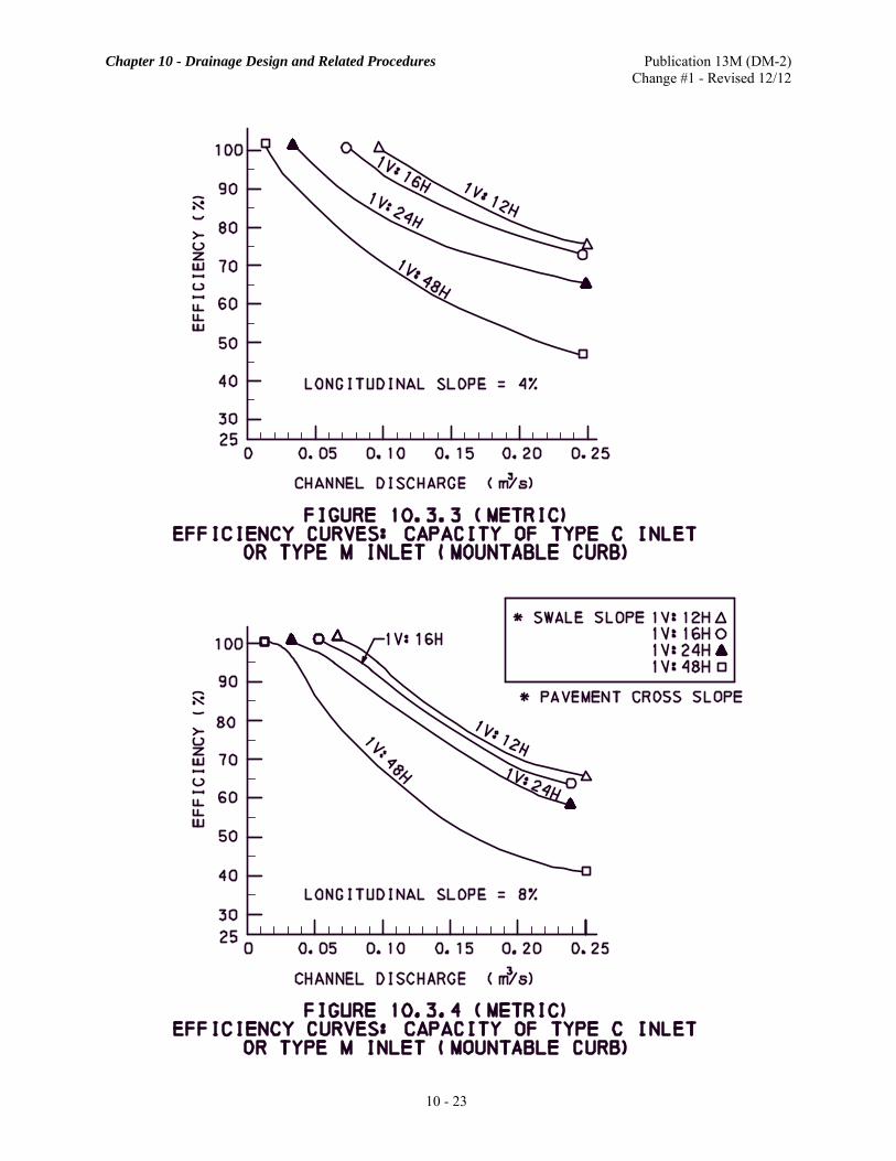
a. Type C Inlet or Type M Inlet (Mountable Curb). The capacities of Type C Inlets or Type M Inlets (mountable curb) on a continuous grade are presented in Table 10.3.1 for a 100% efficiency and in Figure 10.3.1 through Figure 10.3.4 for various percents of efficiency. The efficiency of an inlet is defined as (Q2/Q1) × 100%, where Q1 is the channel flow (m3/s (cfs)) and Q2 is the rate of flow (m3/s (cfs)), intercepted by the inlet gratings. The capacities for these inlets under sump conditions are indicated on Table 10.3.2. b. Type M Inlet (Median) or Type S Inlet. The capacities of Type M Inlets (Median) or Type S Inlets on a continuous grade are presented in Table 10.3.3. The capacities for these inlets under sump conditions are indicated in Figure 10.3.5 and Figure 10.3.6. c. Type D-H Inlet. The hydraulic capacities of the D-H Inlet and its alternate single unit inlet are indicated in Figure 10.3.7.
INTENTIONALLY BLANK

Chapter 10 - Drainage Design and Related Procedures Publication 13M (DM-2) Change #1 - Revised 12/12
10 - 19
TABLE 10.3.1
CAPACITY OF TYPE C INLET OR TYPE M INLET (MOUNTABLE CURB)
LONGITUDINAL SLOPE
(%)
METRIC ENGLISH
SWALE* INLET**
CAPACITY (m3/s)
SWALE* INLET**
CAPACITY (cfs)
0.5 1V:12H 0.042 1V:12H 1.5 0.5 1V:16H 0.042 1V:16H 1.5 0.5 1V:24H 0.008 1V:24H 0.3 0.5 1V:48H 0.006 1V:48H 0.2 2.0 1V:12H 0.079 1V:12H 2.8 2.0 1V:16H 0.059 1V:16H 2.1 2.0 1V:24H 0.051 1V:24H 1.8 2.0 1V:48H 0.017 1V:48H 0.6 4.0 1V:12H 0.096 1V:12H 3.4 4.0 1V:16H 0.074 1V:16H 2.6 4.0 1V:24H 0.034 1V:24H 1.2 4.0 1V:48H 0.011 1V:48H 0.4 8.0 1V:12H 0.068 1V:12H 2.4 8.0 1V:16H 0.057 1V:16H 2.0 8.0 1V:24H 0.034 1V:24H 1.2 8.0 1V:48H 0.014 1V:48H 0.5
*Pavement Cross Slope **100% Efficiency
TABLE 10.3.2 (METRIC) CAPACITY OF TYPE C INLET OR
TYPE M INLET (MOUNTABLE CURB) AT SUMP CONDITION
PAVEMENT CROSS SLOPE
INLET CAPACITY (m3/s)*
TYPE C TYPE M (MOUNTABLE CURB)
1V:48H 0.057 0.057 1V:24H 0.127 0.099 1V:16H 0.218 0.142 1V:12H 0.317 0.142
*Maximum allowable spread of water on pavement and limitation of curb height were considered in determining the inlet capacity.

Chapter 10 - Drainage Design and Related Procedures Publication 13M (DM-2) Change #1 - Revised 12/12
10 - 20
TABLE 10.3.2 (ENGLISH)
CAPACITY OF TYPE C INLET OR TYPE M INLET (MOUNTABLE CURB)
AT SUMP CONDITION
PAVEMENT CROSS SLOPE
INLET CAPACITY (cfs)*
TYPE C TYPE M (MOUNTABLE CURB)
1V:48H 2.0 2.0 1V:24H 4.5 3.5 1V:16H 7.7 5.0 1V:12H 11.2 5.0
*Maximum allowable spread of water on pavement and limitation of curb height were considered in determining the inlet capacity.
INTENTIONALLY BLANK

Chapter 10 - Drainage Design and Related Procedures Publication 13M (DM-2) Change #1 - Revised 12/12
10 - 21

Chapter 10 - Drainage Design and Related Procedures Publication 13M (DM-2) Change #1 - Revised 12/12
10 - 22
Chapter 10 - Drainage Design and Related Procedures Publication 13M (DM-2) Change #1 - Revised 12/12
10 - 23

Chapter 10 - Drainage Design and Related Procedures Publication 13M (DM-2) Change #1 - Revised 12/12
10 - 24

Chapter 10 - Drainage Design and Related Procedures Publication 13M (DM-2) Change #1 - Revised 12/12
10 - 25
TABLE 10.3.3 (METRIC)
CAPACITY OF TYPE M INLET (MEDIAN) OR TYPE S INLET
SLOPES INLET
CAPACITY WITHOUT DIKE
(m3/s)
INLET CAPACITY WITH DIKE (m3/s)*
LONGITUDINAL SWALE BACK 0.30 m
DEPTH 0.25 m
DEPTH 0.15 m
DEPTH
0.5%
1V:12H
1V:2H 1V:4H 1V:6H 1V:8H
1V:12H
0.088 0.102 0.119 0.125 0.130
0.484 0.473 0.464 0.459 0.479
0.385 0.379 0.379 0.377 0.391
0.286 0.286 0.292 0.292 0.306
1V:6H
1V:2H 1V:4H 1V:6H 1V:8H
1V:12H
0.167 0.238 0.255 0.218 0.119
0.470 0.470 0.470 0.462 0.464
0.394 0.411 0.416 0.402 0.379
0.320 0.354 0.362 0.340 0.292
2.0%
1V:12H
1V:2H 1V:4H 1V:6H 1V:8H
1V:12H
0.099 0.099 0.099 0.102 0.105
0.354 0.371 0.433 0.433 0.498
0.292 0.303 0.354 0.351 0.399
0.227 0.235 0.275 0.269 0.303
1V:6H
1V:2H 1V:4H 1V:6H 1V:8H
1V:12H
0.161 0.218 0.255 0.207 0.099
0.467 0.462 0.450 0.464 0.433
0.391 0.402 0.399 0.399 0.354
0.314 0.340 0.351 0.344 0.275
4.0%
1V:12H
1V:2H 1V:4H 1V:6H 1V:8H
1V:12H
0.045 0.057 0.096 0.091 0.091
0.283 0.306 0.371 0.365 0.379
0.224 0.244 0.303 0.295 0.309
0.164 0.181 0.235 0.227 0.235
1V:6H
1V:2H 1V:4H 1V:6H 1V:8H
1V:12H
0.178 0.227 0.246 0.210 0.096
0.337 0.388 0.416 0.416 0.371
0.297 0.348 0.374 0.365 0.303
0.258 0.306 0.331 0.312 0.235
8.0%
1V:12H
1V:2H 1V:4H 1V:6H 1V:8H
1V:12H
0.042 0.057 0.079 0.076 0.068
0.261 0.249 0.263 0.258 0.269
0.207 0.201 0.218 0.212 0.218
0.153 0.153 0.173 0.167 0.167
1V:6H
1V:2H 1V:4H 1V:6H 1V:8H
1V:12H
0.147 0.176 0.195 0.176 0.079
0.346 0.391 0.399 0.382 0.263
0.297 0.337 0.348 0.331 0.218
0.246 0.283 0.297 0.280 0.173
* Height of dike is dependent on the longitudinal slope, width available and depth of water desired over the inlet grate.

Chapter 10 - Drainage Design and Related Procedures Publication 13M (DM-2) Change #1 - Revised 12/12
10 - 26
TABLE 10.3.3 (ENGLISH)
CAPACITY OF TYPE M INLET (MEDIAN) OR TYPE S INLET
SLOPES INLET
CAPACITY WITHOUT DIKE
(cfs)
INLET CAPACITY WITH DIKE (ft3/s)*
LONGITUDINAL SWALE BACK 12 in
DEPTH 9 in
DEPTH 6 in
DEPTH
0.5%
1V:12H
1V:2H 1V:4H 1V:6H 1V:8H
1V:12H
3.1 3.6 4.2 4.4 4.6
17.1 16.7 16.4 16.2 16.9
13.6 13.4 13.4 13.3 13.8
10.1 10.1 10.3 10.3 10.8
1V:6H
1V:2H 1V:4H 1V:6H 1V:8H
1V:12H
5.9 8.4 9.0 7.7 4.2
16.6 16.6 16.6 16.3 16.4
13.9 14.5 14.7 14.2 13.4
11.3 12.5 12.8 12.0 10.3
2.0%
1V:12H
1V:2H 1V:4H 1V:6H 1V:8H
1V:12H
3.5 3.5 3.5 3.6 3.7
12.5 13.1 15.3 15.3 17.6
10.3 10.7 12.5 12.4 14.1
8.0 8.3 9.7 9.5
10.7
1V:6H
1V:2H 1V:4H 1V:6H 1V:8H
1V:12H
5.7 7.7 9.0 7.3 3.5
16.5 16.3 15.9 16.4 15.3
13.8 14.2 14.1 14.1 12.5
11.1 12.0 12.4 11.8 9.7
4.0%
1V:12H
1V:2H 1V:4H 1V:6H 1V:8H
1V:12H
1.6 2.0 3.4 3.2 3.2
10.0 10.8 13.1 12.9 13.4
7.9 8.6
10.7 10.4 10.9
5.8 6.4 8.3 8.0 8.3
1V:6H
1V:2H 1V:4H 1V:6H 1V:8H
1V:12H
6.3 8.0 8.7 7.4 3.4
11.9 13.7 14.7 14.7 13.1
10.5 12.3 13.2 12.9 10.7
9.1 10.8 11.7 11.0 8.3
8.0%
1V:12H
1V:2H 1V:4H 1V:6H 1V:8H
1V:12H
1.5 2.0 2.8 2.7 2.4
9.2 8.8 9.3 9.1 9.5
7.3 7.1 7.7 7.5 7.7
5.4 5.4 6.1 5.9 5.9
1V:6H
1V:2H 1V:4H 1V:6H 1V:8H
1V:12H
5.2 6.2 6.9 6.2 2.8
12.2 13.8 14.1 13.5 9.3
10.5 11.9 12.3 11.7 7.7
8.7 10.0 10.5 9.9 6.1
* Height of dike is dependent on the longitudinal slope, width available and depth of water desired over the inlet grate.

Chapter 10 - Drainage Design and Related Procedures Publication 13M (DM-2) Change #1 - Revised 12/12
10 - 27

Chapter 10 - Drainage Design and Related Procedures Publication 13M (DM-2) Change #1 - Revised 12/12
10 - 28

Chapter 10 - Drainage Design and Related Procedures Publication 13M (DM-2) Change #1 - Revised 12/12
10 - 29

Chapter 10 - Drainage Design and Related Procedures Publication 13M (DM-2) Change #1 - Revised 12/12
10 - 30

Chapter 10 - Drainage Design and Related Procedures Publication 13M (DM-2) Change #1 - Revised 12/12
10 - 31
Preliminary inlet spacing may be estimated from the following formula giving due consideration to the percentage of water bypassing the inlet and, on curbed sections, the permissible encroachment of water on the roadway pavement.
METRIC ENGLISH
CIWQ)10)(63.3(L
6=
CIWQ)560,43(L =
where: L = Inlet spacing (m (ft)).
Q = Discharge capacity of the drainage facility (inlet, shoulder, swale, curb sections, etc.) with the least capacity (m3/s (cfs)).
C = Rational method coefficient. I = Rainfall intensity (mm/h (in/h)), generally for a 10-year storm. W = Average width of contributing area (m (ft)).
Determine the required inside dimensions of the inlet box based on the required reinforced concrete pipe size and pipe opening. Once the minimum inside dimensions are determined, refer to Table 10.3.4 to determine the required inlet box type. For additional information, refer to Publication 72M, Roadway Construction Standards.
TABLE 10.3.4 DETERMINING INLET BOX TYPES
INLET BOX TYPE
INSIDE WIDTH mm (in)
INSIDE LENGTH mm (in)
MAXIMUM PERMITTED
PIPE DIAMETER
ALONG WIDTH mm (in)
MAXIMUM PERMITTED
PIPE DIAMETER
ALONG LENGTH mm (in)
STANDARD 610 mm (24") 1150 mm (45 1/4") 457 mm (18") 914 mm (36") 4 1220 mm (48") 1220 mm (48") 914 mm (36") 914 mm (36") 5 1524 mm (60") 1524 mm (60") 1066 mm (42") 1066 mm (42") 6 1828 mm (72") 1828 mm (72") 1372 mm (54") 1372 mm (54") 7 2134 mm (84") 2134 mm (84") 1676 mm (66") 1676 mm (66") 8 2438 mm (96") 2438 mm (96") 1828 mm (72") 1828 mm (72") 9 2744 mm (108") 2744 mm (108") 2134 mm (84") 2134 mm (84")
10 3048 mm (120") 3048 mm (120") 2438 mm (96") 2438 mm (96") D-H 762 mm (30") 2516 mm (99") 457 mm (18") 1828 mm (72")
Chapter 10 - Drainage Design and Related Procedures Publication 13M (DM-2) Change #1 - Revised 12/12
10 - 32
Final spacing should be confirmed based on allowable spread. Inlet grates are cast iron or structural steel and shall conform to the dimensional requirements to ensure proper installation (1212 mm × 673 mm (47.75 in × 26.5 in)), as shown on Publication 72M, Roadway Construction Standards. A bicycle-safe grate shall be installed for all inlets in areas where bicycle traffic is anticipated, such as curbed roadways in urban areas or for roadways specifically established and signed as bikeways or having bike lanes. Additional information is found in HEC-22. On curbed sections, an inlet shall be placed at the low point on sag vertical curves with flanking inlets on each side of the low point at a distance not to exceed 30 m (100 ft) or at a grade not greater than 60 mm (0.20 ft) above the sag inlet. The distance between the flanking inlet and the inlet at the low point may be computed using HEC-22, Chapter 4. On shoulder (without swale) or curb sections, the maximum spacing of inlets shall not exceed 140 m (450 ft), except where a Type D-H Inlet or the alternate single unit inlet is used. Inlet spacing in depressed median sections and shoulder swale areas shall not exceed 280 m (900 ft).
B. Storm Sewer Systems.
1. Preliminary Layout. The first step in storm drain design is to develop a conceptual storm drain layout, including inlet, access hole, and pipe locations. This is usually completed on a plan that shows the roadway, adjacent land use conditions, intersections, and under/overpasses. Surface utilities, underground utilities, and any other storm drain systems shall also be shown. Tentative inlets, junctions, and access locations shall be identified based primarily on obvious project requirements and limitations, such as low points and intersections.
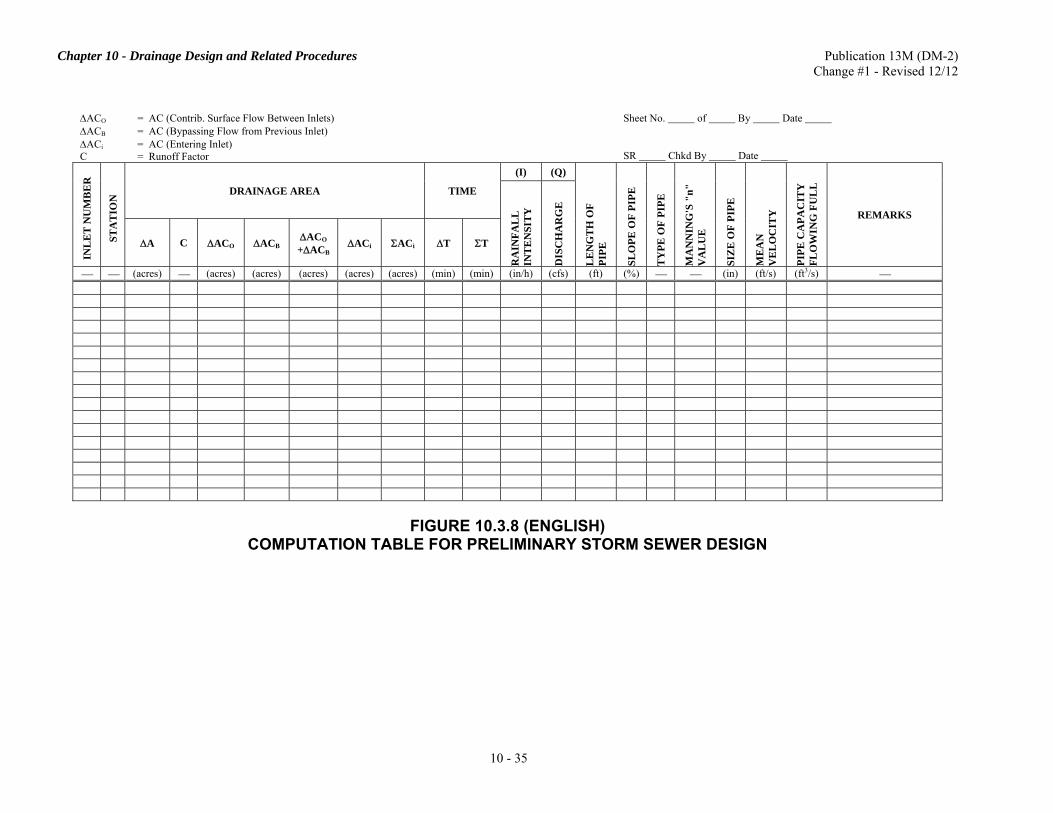
2. Pipe Sizing. Given the preliminary layout, it is possible to begin the hydraulic analysis necessary to size the storm drain system. The method used to size storm pipes is based on a gravity or non-pressure flow concept, which shall generally be adopted for design on the Department's projects. In areas of an extreme flat grade, where a realistic size cannot be attained by means of the usual gravity flow design, a special design based on a pressure flow concept may be considered. Preliminary pipe size may be calculated using a full-flow assumption given the discharge and pipe slope. This approach does not account for minor losses. If a pressure flow concept is used, minor losses are to be accounted for in the Hydraulic Grade Line (HGL) calculation. An example of a computation table for a storm sewer design layout is shown in Figure 10.3.8 or HEC-22, Section 7.4. Publication 584, PennDOT Drainage Manual, Chapter 13 has a detailed HGL computation form.
The minimum diameter of storm pipe shall be 450 mm (18 in) for circular pipe (or equivalent size pipe arch), except pipes under a 7.6 m (25 ft) or greater fill height shall not be less than 600 mm (24 in). Storm pipes are provided in 75 mm (3 in) increments up to the 900 mm (36 in) diameter size and 150 mm (6 in) increments for those exceeding 900 mm (36 in) diameter size. Avoid abrupt changes in direction or slope of pipe. Where such abrupt changes are required, place an inlet or manhole at the point of change. The minimum slope in a pipe shall not be less than 0.35%. Place storm pipes on the most economical slope and at the most economical depth.
Provide 300 mm (12 in) minimum cover from the top of pipe barrel to bottom of base course. Refer to Publication 72M, Roadway Construction Standards, RC-30M for details concerning minimum cover over pipe under pavements. For special design and modeling of pipes, refer to Publication 15M, Design Manual, Part 4, Structures, Appendix H.

Chapter 10 - Drainage Design and Related Procedures Publication 13M (DM-2) Change #1 - Revised 12/12
10 - 33
Ductile iron pipe may be used when: (1) the minimum cover is at least 75 mm (3 in) but less than 150 mm (6 in) from the top of pipe barrel to the subgrade elevation; and (2) high impact and concentrated heavy loadings are involved. Under these conditions, provide a ductile iron pipe with a minimum 3-edge bearing strength of 17.8 kN/m (4000 lb/ft) times the diameter in meters (feet). A minimum drop of 50 mm (2 in) shall be provided in the inlet or other junction structure between the lowest inlet pipe invert elevation and the outlet pipe invert elevation. When there is a change in pipe size in an inlet or other junction structure, the elevation of the lowest invert of the incoming pipes shall not be less than that of the outlet pipe. The Manning's roughness coefficients for corrugated metal pipes are included in Publication 584, PennDOT Drainage Manual, Table 7.4. In general, the size of a downstream storm pipe should not be smaller than that of the upstream storm pipe(s). This requirement is not an absolute criterion and sound engineering judgment should be exercised in making the determination. As an example, it would not be economical to purposely adopt a long stretch of downstream storm pipes equal to or larger than an upstream slope pipe where the size of the slope pipe is hydraulically determined by entrance conditions.
INTENTIONALLY BLANK

Chapter 10 - Drainage Design and Related Procedures Publication 13M (DM-2) Change #1 - Revised 12/12
10 - 34
ΔACO = AC (Contrib. Surface Flow Between Inlets) ΔACB = AC (Bypassing Flow from Previous Inlet) ΔACi = AC (Entering Inlet) C = Runoff Factor
Sheet No. of By Date SR Chkd By Date
INL
ET
NU
MB
ER
STA
TIO
N DRAINAGE AREA TIME
(I) (Q)
LE
NG
TH
OF
PIPE
SLO
PE O
F PI
PE
TY
PE O
F PI
PE
MA
NN
ING
'S "
n"
VA
LU
E
SIZ
E O
F PI
PE
ME
AN
V
EL
OC
ITY
PIPE
CA
PAC
ITY
FL
OW
ING
FU
LL
REMARKS
RA
INFA
LL
IN
TE
NSI
TY
DIS
CH
AR
GE
ΔA C ΔACO ΔACB ΔACO +ΔACB ΔACi ΣACi ΔT ΣT
⎯ ⎯ (ha) ⎯ (ha) (ha) (ha) (ha) (ha) (min) (min) (mm/h) (m3/s) (m) (%) ⎯ ⎯ (mm) (m/s) (m3/s) ⎯
FIGURE 10.3.8 (METRIC)
COMPUTATION TABLE FOR PRELIMINARY STORM SEWER DESIGN
Chapter 10 - Drainage Design and Related Procedures Publication 13M (DM-2) Change #1 - Revised 12/12
10 - 35
ΔACO = AC (Contrib. Surface Flow Between Inlets) ΔACB = AC (Bypassing Flow from Previous Inlet) ΔACi = AC (Entering Inlet) C = Runoff Factor
Sheet No. of By Date SR Chkd By Date
INL
ET
NU
MB
ER
STA
TIO
N DRAINAGE AREA TIME
(I) (Q)
LE
NG
TH
OF
PIPE
SLO
PE O
F PI
PE
TY
PE O
F PI
PE
MA
NN
ING
'S "
n"
VA
LU
E
SIZ
E O
F PI
PE
ME
AN
V
EL
OC
ITY
PIPE
CA
PAC
ITY
FL
OW
ING
FU
LL
REMARKS
RA
INFA
LL
IN
TE
NSI
TY
DIS
CH
AR
GE
ΔA C ΔACO ΔACB ΔACO +ΔACB ΔACi ΣACi ΔT ΣT
⎯ ⎯ (acres) ⎯ (acres) (acres) (acres) (acres) (acres) (min) (min) (in/h) (cfs) (ft) (%) ⎯ ⎯ (in) (ft/s) (ft3/s) ⎯
FIGURE 10.3.8 (ENGLISH)
COMPUTATION TABLE FOR PRELIMINARY STORM SEWER DESIGN

Chapter 10 - Drainage Design and Related Procedures Publication 13M (DM-2) Change #1 - Revised 12/12
10 - 36
3. Computation of Hydraulic Grade Line. When pressure flow methods are used to design the pipe system, the Hydraulic Grade Line computations must be provided. Pressure flow through a pipe typically results in the pressure head to be above the top of the pipe (i.e., not equal to the depth of flow in the pipe). In this case, the pressure head rises to a level represented by the hydraulic grade line (HGL). The HGL is used to aid the designer in determining the elevation to which water will rise when the system is operating under design conditions. Preliminary methods to compute the hydraulic grade line of a pipe system shall adhere to the guidelines indicated in HEC-22, Section 7.5. The HGL shall be established to evaluate overall system performance and ensure that at the design discharge, the storm drain system does not inundate or adversely affect inlets, access holes, or other appurtenances. The first step in calculating the HGL is to establish the location of all hydraulic controls along the pipe alignment and locations where the water surface shall not be exceeded. These may occur at the inlet, at the outlet, or at intermediate points along the alignment. The water surface elevation of the channel into which the storm drain discharges may establish the maximum tailwater. The first reach is defined from the downstream control point, or outlet, to the first hydraulic structure or pipe grade break. Subsequent reaches are defined between hydraulic structures and/or grade breaks. The calculation proceeds on a reach-by-reach basis from the given control point and proceeds upstream. The calculation is based on application of the energy equation as major losses are calculated within each reach. The designer shall note that the procedure is based on the assumption of a uniform hydraulic gradient within a conduit reach and that minor losses under supercritical flow are ignored.
4. Alternate Pipe Designs. A summary of acceptable criteria for specifying alternate types of storm or culvert pipes based on the type of use is presented in Table 10.3.5. The selection of pipe alternates is also dependent upon environmental factors. Consideration to the future land use should be given. For example, pipe placed in an area not being mined presently, but which may ultimately be mined, should be designed to handle the mine acid drainage. The criteria indicated in Table 10.3.5 are applicable to all sizes of pipes. The approximate expected service life has been specified as a primary design parameter in the alternate pipe selection criteria indicated in Table 10.3.5.
In those cases where the Department's design criteria specifies that alternate pipes shall be included in the plans and proposal, design computations shall be submitted for each alternate. If the design computations determine that, for one or more of the alternates, different sizes are adequate, the construction drawings and quantities should be developed for the larger size; however, the alternate sizes should be indicated on the tabulation and/or summary sheet when a choice in size exists. Where the pipe design is sensitive to a certain kind of metal pipe corrugation, the contractor shall be alerted by a "special provision" that a certain type of pipe corrugation is required at a particular location. If an alternate type and size of pipe is selected and approved as a Value Engineering proposal during construction, the drawings and quantities must be adjusted accordingly by the contractor.
5. Combination Storm Sewer and Underdrain. Longitudinal pipes that are proposed along the low side of pavement or shoulder edges may serve as combination storm sewer and underdrain pipe to eliminate the need for base drains, and shall be designed and constructed in accordance with Publication 72M, Roadway Construction Standards and Publication 408, Specifications. In these cases, the effect of subgrade drainage should be excluded in the design of the storm sewer system.
6. End Sections. End sections should be used on the inlet end of pipes that accept flows at grade due to their favorable hydraulic characteristics. Headwalls are usually used on the inlet end of culverts. End sections may be used when it is desirable to conform the entrance condition to the fill slope. Both headwalls and end sections perform the same hydraulically on the inlet end. End sections are used on the outlet end of the pipe to reduce the flow depth and outlet velocity. End sections on the outlet end of pipes should be used on traversable slopes (without guide rail) within the clear zone and in highly visible areas; i.e., interchange loops and median swales. For economic reasons, the use of end sections on the outlet end of pipe culverts, at certain locations, is not required.

Chapter 10 - Drainage Design and Related Procedures Publication 13M (DM-2) Change #1 - Revised 12/12
10 - 37
TABLE 10.3.5 ALTERNATE PIPE SELECTION CRITERIA BASED UPON
LOCATION OF DRAINAGE PIPES
LOCATION OF DRAINAGE PIPES TYPES OF PIPE NO. OF
ALTERNATES REQUIRED
Cross Drains Under Pavement, Shoulder, or Between Curbs; Parallel Storm Sewers Under Pavement or Between Curbs
Fill Height* Interstate/ Arterials
Collectors/ Locals
2
< 0.6 m (< 2 ft)
100 Years Life (Pipes 1, 2, 5 & 7)
50 Years Life (Pipes 1 & 3 thru 7)
0.6 m - 4.6 m (2 ft - 15 ft)
100 Years Life (Pipes 1, 2, 5 & 7)
50 Years Life (Pipes 1 & 3 thru 7 & 8)
> 4.6 m (> 15 ft)
100 Years Life (Pipes 1, 2, 5 & 7)
100 Years Life (Pipes 1, 2, 5 & 7)
Parallel Storm Sewers Outside of Pavement or Curbs
50 Years Life (All pipes in LEGEND) 3
Cross Drains Outside of Pavement, Shoulder or Curbs (Cross Drains in Medians, etc.)
50 Years Life (All pipes in LEGEND except 9) 3
Combination Storm Sewer and Underdrain and Other Special Drainage System
100 Years Life● Pipe 2, open joint, & perforated pipes 5 & 7 2
50 Years Life●●
Fill Height* < 0.6 m (2 ft)
Pipe 3, open joint, & perforated pipes 4, 5 & 7 3 Fill Height*
≥ 0.6 m (2 ft) Pipe 3, open joint, & perforated pipes 4, 5, 7 & 8
Slope Pipes 50 Years Life ( Pipes 4 thru 9) 2 Side Drains (Driveways, etc.) 25 Years Life (All pipes in LEGEND) 3
Separate tables are provided for fill height requirements. Utilize those tables for determination of minimum and maximum fill height requirements. Specified minimum fill heights are applicable to pipes under pavement or between curbs. Specified maximum fill heights are applicable to all installations. * Fill height is defined as the material from the top of pipe barrel to the riding surface, including the pavement structure. Refer to RC-30M for minimum cover over pipe under pavements. ● For pipes under pavement or between curbs on Interstate/Arterials. ●● For pipes other than under pavement or between curbs on Interstate/Arterials.
LEGEND (Types of Pipe)
1. DIP = Ductile Iron Pipe. 2. RCP (Type A) = Reinforced Concrete Pipe, heavy duty. 3. RCP (Type B) = Reinforced Concrete Pipe, normal duty (1200 mm (48 in) max). 4. CGSP = Corrugated Galvanized Steel Pipe. 5. CASP = Corrugated Aluminized Steel Pipe. 6. CCGSP = Coated (Polymer) Corrugated Galvanized Steel Pipe. 7. CAAP = Corrugated Aluminum Alloy Pipe. 8. TP (Group I, II, III, IV or VI) = Thermoplastic Pipe, Group I, II, III, IV or VI (1500 mm (60 in) max). Thermoplastic Pipe
Groups are defined in Publication 408, Specifications, Section 601. 9. TP (Group V - Corr PE) = Thermoplastic Pipe, Group V - Corrugated Polyethylene (900 mm (36 in) max). Thermoplastic
Pipe Groups are defined in Publication 408, Specifications, Section 601. NOTES: 1. Select pipes with specified years life based on the type of drainage installation, class of highway and fill height (cover).
The years life indicated (100, 50 and 25) are approximate expected service lives. 2. Pipe alternates may be eliminated for the following reasons: (1) unstable support, (2) high impact and concentrated
loading, (3) high embankments, (4) limited clearance, (5) steep gradients, (6) high acidity to alkalinity of soils and water or other corrosive elements, (7) high erosive forces or (8) for other pertinent reasons.

Chapter 10 - Drainage Design and Related Procedures Publication 13M (DM-2) Change #1 - Revised 12/12
10 - 38
7. Energy Dissipators. Energy dissipation may be required to protect the channel downstream of a storm drain outlet. Protection often is required at the outlet to prevent erosion of the outfall bed and banks. Riprap aprons or energy dissipators shall be provided if high velocities are expected. Refer to Publication 584, PennDOT Drainage Manual, Chapter 12 for guidance with designing an appropriate dissipator. The FHWA computer program HY-8 may be used for design calculations for energy dissipation.
8. Maintenance of Existing Pipes. Existing pipes may be selected to remain in place and to function beyond completion of the proposed work. These existing pipes should be inspected by the designer during the design phase to determine if they need to be cleaned. For cleaning existing pipes, the contractor is to follow the specifications presented in Publication 408, Specifications, Section 601. The designer shall present the location (stations), length (meters (linear feet)) and size (diameter) of each pipe to be cleaned as part of the project. The listing shall be included on the "Tabulation of Quantities" sheet(s) and "Summary" sheet(s) in the design plans and quantified under one of the following two item descriptions:
• Cleaning Existing Pipe Culverts, Diameters Up to and Including 900 mm (36 in) • Cleaning Existing Pipe Culverts, Diameters over 900 mm (36 in)
C. Pipe Culverts. The function of a pipe culvert is to convey surface water across or from the highway right-of-way. (For structures within regulated waterways, see Section 10.6.) Pipe culverts are usually covered with embankment and are composed of structural material around the entire perimeter, although some are supported on spread footings with the stream bed serving as the bottom of the culvert. In all cases where drainage is collected by means of a head wall, the pipe shall be designed as a pipe culvert. When a pipe culvert is part of a storm sewer system and crosses the roadway, it shall be designed with the same design storm as the remainder of the system. The procedure contained in Publication 584, PennDOT Drainage Manual, Chapter 9, and in FHWA's Hydraulic Design Series No. 5 (HDS-5), shall be used for the design of pipe culverts. Specific information about pipe culverts is as follows:
1. Diameters. The minimum diameter of a pipe culvert shall be 450 mm (18 in), except pipes under a 7.6 m (25 ft) or greater fill height shall not be less than 600 mm (24 in). Culverts shall be provided in 150 mm (6 in) increments. 2. Inverts. Inverts of new pipe culverts shall be depressed a minimum of 150 mm (6 in) below stream invert grade at both the inlet and outlet ends, or a minimum of 300 mm (12 in) if required as a condition to obtain the waterway permit. 3. Lengths. Because of the difference between the lengths of metal and non-metal end sections for pipe culverts, the length of connecting pipe can vary. To avoid showing different lengths of the connecting pipe on the plans, the designer should show on the plan only the length of the metal type pipe for all alternatives. 4. Allowable Headwater. In culvert design, headwater is water that effectively ponds at the entrance end of the culvert. The allowable headwater elevation is that elevation above which damage may be caused to adjacent property and/or the roadway. The maximum allowable headwater (HW) is the depth of water, measured from the entrance invert, that can be ponded during the design flood. The surrounding features, flow limitations, and roadway classification must be considered for each situation.
The surrounding features that may limit the allowable headwater include the following:
• Lowest elevation of the roadway adjacent to the ponding area; • Flowline of the roadway ditch which passes water along the roadway to another drainage basin; • Upstream property, such as buildings or farm crops, which will be damaged if inundated; and • Elevation established to delineate floodplain zoning.

Chapter 10 - Drainage Design and Related Procedures Publication 13M (DM-2) Change #1 - Revised 12/12
10 - 39
Flow limitation factors that can affect the allowable headwater include the following: • The debris which could plug the structure; • Excessive ponding which would allow too much silting; or • High hydrostatic pressure which would cause seepage along the culvert backfill.
The HW/D ratio to be considered for design is the ratio of headwater depth to the diameter, height, or rise of a culvert entrance. The following are the maximum allowable HW/D ratios for the design of new culverts:
• HW/D = 2.0: Circular and elliptical (squash) pipe culverts with diameters (or equivalent diameters)
of 750 mm (30 in) or less. • HW/D = 1.5: Circular and elliptical pipe culverts with diameters greater than 750 mm (30 in) and
less than or equal to 1800 mm (72 in), and other culverts with cross sectional areas equal to or less than 2.8 m2 (30 ft2).
• HW/D = 1.2: Circular and elliptical pipe culverts with diameters greater than 1800 mm (72 in), and
other culverts with cross sectional areas greater than 2.8 m2 (30 ft2). The maximum allowable headwater ratio applies to the design flood, based on roadway classification. The headwater should also be checked for the 100-year flood to ensure compliance with floodplain management criteria. The maximum acceptable outlet velocity should be identified. The headwater should be set to produce acceptable velocities; otherwise, stabilization or energy dissipation should be provided where acceptable velocities are exceeded. For streams with debris issues, trash racks should be considered.
Occasional flowage easement shall normally be obtained for new flooding areas beyond the right-of-way line for the 100-year storm event for flow (Q100). Q100 shall be used to be consistent with FEMA requirements and the Pennsylvania Floodplain Management Act. Except for the Interstate Highway, which cannot be inundated at the 50-year storm event for flow (Q50), all classes of highways may be inundated at the design Q if a practicable alternative is not available.
5. Erosion Control. The requirements and provisions of erosion control devices for pipe culvert outlets are specified in Chapter 13, Erosion and Sediment Pollution Control.
D. Pavement Base Drains. Pavement base drains are subsurface drains utilizing perforated or porous pipe installed parallel to the highway. They are used to lower the ground water level, to drain slopes or to drain the pavement structure. The pipe is placed in trenches and surrounded by coarse aggregate that is both pervious to water and capable of protecting the pipe from infiltration by the surrounding soil. Installation details are presented in Publication 72M, Roadway Construction Standards and in Chapter 1, Section 1.5. To provide a functional pavement base drain system, the proper spacing of outlets is important, especially on relatively flat grades. Therefore, the various types of pipe can be made hydraulically equivalent by the proper selection of outlet spacing for each type. Circular diameters between 100 mm (4 in) and 200 mm (8 in) typically are used and are considered adequate for normal use. Where such pipe is required to connect into existing systems, or if hydraulic circumstances exist that require greater capacities, larger pipe sizes should be specified. Publication 35, Approved Construction Materials (Bulletin 15) provides a listing of approved pavement base drains made from various materials. The following method should be used to determine the maximum functional outlet spacing for pavement base drains. Roughness coefficients for the various types of pipe for pavement base drains are indicated in Table 10.3.6. Outlet spacing is a function of the pipe diameter, pipe gradient (g) and the anticipated design infiltration rate (I). The maximum functional outlet spacing for various conditions may readily be determined from the nomograph in Figure 10.3.9.

Chapter 10 - Drainage Design and Related Procedures Publication 13M (DM-2) Change #1 - Revised 12/12
10 - 40
First determine the infiltration rate by multiplying the appropriate 1 hour/1 year frequency precipitation rate obtained from Publication 584, PennDOT Drainage Manual, Chapter 7, Appendix A by an adjustment coefficient of 0.50 for asphaltic concrete pavement or 0.67 for portland cement concrete pavement. Enter the left side of the nomograph with the calculated design infiltration rate. Next, draw a line from the design infiltration rate through the appropriate width of pavement or maximum perpendicular drainage distance to the trench. Normally this can be simplified by passing this line through the appropriate number of lanes sloped towards each pavement base drain. This line intercepts PIVOT LINE (2). Now enter the right side of the nomograph with the pipe gradient value. Generally, the pipe gradient should approximately follow the longitudinal grade of the highway pavement; hence a minimum gradient of 0.5% would apply. Draw a line from the pipe gradient through the pipe diameter and appropriate n-coefficient by type of pipe until it intercepts PIVOT LINE (1). By connecting the points of interception of PIVOT LINES (1) and (2) with a straight line, the maximum functional distance (L) between outlets, in meters (feet), can be obtained. If the resultant maximum outlet spacing for the given set of conditions is too small to be practically applied on a particular project, the pipe diameter or pipe gradient may be increased or a pipe with a lower n-coefficient selected.
TABLE 10.3.6 ROUGHNESS COEFFICIENT "n"
FOR MANNING'S EQUATION FOR PAVEMENT BASE DRAINS
MANNING'S "n" TYPES OF PIPE 0.010 Polyvinyl Chloride (PVC) with Smooth Inner Walls
0.012
Porous Cement Concrete Pipe; Helically Corrugated Circular Metal Pipe (100 mm through 200 mm (4 in through 8 in)); Corrugated High–Density Polyethylene (HDPE) with Smooth Inner Walls
0.015 Corrugated High-Density Polyethylene (HDPE) with Corrugated Inner Walls; Helically Corrugated Circular Metal Pipe (250 mm (10 in))
INTENTIONALLY BLANK

Chapter 10 - Drainage Design and Related Procedures Publication 13M (DM-2) Change #1 - Revised 12/12
10 - 41

Chapter 10 - Drainage Design and Related Procedures Publication 13M (DM-2) Change #1 - Revised 12/12
10 - 42

Chapter 10 - Drainage Design and Related Procedures Publication 13M (DM-2) Change #1 - Revised 12/12
10 - 43
Example Problem: Given: A two-lane asphaltic concrete pavement in Delaware County. Determine: The maximum functional outlet spacing for a perforated 100 mm (4 in) diameter, smooth-walled
PVC pipe (pavement base drain on both sides of roadway). Assume a gradient of 0.5% (0.005).
Solution: From Publication 584, PennDOT Drainage Manual, Chapter 7, Appendix A, Table 7A.1, the 1-year, 1 hour intensity would correspond to Map A. From Map A, Figure 7A.1, Delaware County, would fall under Region 5. From Table 7A.6a and (b) the 1-year, 1-hour rainfall would be 29.6 mm/h (1.17 in/h) precipitation rate in Delaware County. This multiplied by an adjustment factor of 0.50 for asphaltic concrete pavement gives an infiltration intensity, I, of 14.8 mm/h (0.59 in/h). Enter the left side of Figure 10.3.9 at the 14.8 (0.59) location. Next extend a line through the 1 lane mark (base drain on both sides of roadway) to PIVOT LINE (2). Now extend a line from the 0.5% (0.005) pipe gradient location on the right side of the nomograph through the 100 mm (4 in), n = 0.010 mark to PIVOT LINE (1). Draw a line from PIVOT LINE (1) to PIVOT LINE (2) and read a maximum outlet spacing of 277.6 m (910 ft) from the intersection point on DISTANCE BETWEEN OUTLETS line (L).
E. Stormwater Management Facilities. See Chapter 13, Erosion and Sediment Pollution Control, and Publication 584, PennDOT Drainage Manual, Chapter 14 regarding design of stormwater management facilities. F. Superstructure Drainage. See Publication 15M, Design Manual, Part 4, Structures, for specific instructions regarding superstructure drainage. G. Roadway Drainage Report. The outline shown below is an example of a Roadway Drainage Report that would be prepared and submitted for the Department's review and approval where an individual water obstruction permit or Highway Occupancy Permit is required. Note that this outline is a guideline and may be modified to meet the specific needs of the project. 1. INTRODUCTION 2. PROJECT DESCRIPTION 3. EXISTING DRAINAGE CONDITIONS 4. PROPOSED DRAINAGE CONDITIONS 5. HYDROLOGIC CRITERIA AND METHODOLOGY (Describe hydrologic criteria and solution methodology as selected specifically for the project) 6. HYDRAULIC CRITERIA
(Describe hydraulic criteria and solution methodology for each hydraulic structure as applicable to the project)
a. Inlets
b. Storm Pipes c. Pipe Culverts d. Ditches and Swales e. Pavement Base Drains 7. CONCLUSION 8. REFERENCES 9. DRAINAGE PLAN SHEETS WITH AREA DELINEATIONS 10. APPENDICES
Chapter 10 - Drainage Design and Related Procedures Publication 13M (DM-2) Change #1 - Revised 12/12
10 - 44
Appendix A: Inlet Calculations Appendix B: Storm Pipe Calculations Appendix C: Circular Pipe Culvert Calculations Appendix D: Ditch and Swale Calculations Appendix E: Pavement Base Drain Calculations H. Hydraulic Computation Approval. Hydraulic design computations shall be required for all pipes with a diameter of 450 mm (18 in) or greater. These pipes refer to any closed conduit which conveys storm water runoff, including culverts, which provide cross drainage of the highway.
Hydraulic computations for roadway drainage structures shall be approved at the District Office with one copy of the submission and approval for all projects sent to the Central Office, Bureau of Project Delivery for information, according to the procedures specified in Section 10.2. The Central Office may perform a Quality Assurance review of the submission and forward any comments on major policy deviations to the District Office. One copy of the plans should accompany the hydraulic computations showing pipe sizes (alternates where required) selected for each location. The pipe sizes and types should be shown on the prints at the pipe location for review purposes. For those roadway drainage structures where an individual water obstruction permit is required, a brief Hydrologic and Hydraulic Report prepared as per Section 10.7 should be included in the permit application as required by 25 PA Code § 105. 10.4 FILL HEIGHT CRITERIA AND TABLES FOR CONCRETE, METAL AND THERMOPLASTIC PIPES The design criteria and tables referred to in this section contain the maximum and minimum allowable fill height information for reinforced concrete, metal and thermoplastic pipes. As previously indicated in Table 10.3.5, fill height is defined as the material from the top of the pipe barrel to the riding surface, including the pavement structure. Refer to Publication 72M, Roadway Construction Standards, RC-30M for details concerning minimum cover over pipe under pavements. In the tables found in Chapter 10, Appendix B, the type of pipe indicated is based on their corresponding diameters for circular pipes, corresponding rise × span for reinforced concrete elliptical pipes and corresponding span × rise for metal pipe arches. A. Reinforced Concrete Pipes and Elliptical Pipes. The design criteria and tables including those for allowable fill heights are provided in the Publication 218M, Standards for Bridge Design, Drawing BD-636M titled, "Standard, Reinforced Concrete Pipes." Standard fill height tables included in BD-636M are listed in Chapter 10, Appendix B, Table 10.B.1. B. Metal Pipes and Pipe Arches. Chapter 10, Appendix B, Table 10.B.2 lists those types of metal pipes and pipe arches for which allowable fill height tables have been developed. Chapter 10, Appendix B, Tables 10.B.3 through 10.B.34 provide the maximum and minimum allowable fill height information for commonly used metal pipes and pipe arches. Refer to Publication 15M, Design Manual, Part 4, Structures, for pipe diameters or pipe arch spans 2400 mm (96 in) or more. The allowable fill height table for metal pipes and pipe arches were developed using the following criteria: γe = 2240 kg/m3 (140 lb/ft3) Φ = 0.98 for helical pipes Min fill heights as per SCI method (DM-4 - 95% compaction) Live Load = HS-25 trucks (passing distance = 1.2 m (4 ft)) 254 mm × 508 mm (10 in × 20 in) wheel footprint Live Load impact factor, IM = 40(1 - 0.125H) Load Factor Design βe = 1.5 for flexible culverts (Group × loading)

Chapter 10 - Drainage Design and Related Procedures Publication 13M (DM-2) Change #1 - Revised 12/12
10 - 45
Service Load Check βe = 1.0 SF = 1.3 at end of service life Service Life Metal Loss rates: 0.05 mm/yr (2 mil/yr) for plain galvanized pipes 0.025 mm/yr (1 mil/yr) for aluminized steel or aluminum pipes Treatment Credits: Polymer Coating - 20 yr service life credit when design flow velocity ≤ 1.5 m/s (5.0 ft/s) Polymer Coating - 10 yr service life credit when design flow velocity > 1.5 m/s (5.0 ft/s) Recommended Installation Conditions: Steel-soil and water pH within the range of 5.5 to 8.5 Aluminum - soil and water pH within the range of 4 to 8.5 C. Thermoplastic Pipes. The maximum and minimum allowable fill heights for Thermoplastic Pipe Groups I, II, III, IV, V and VI are indicated in Chapter 10, Appendix B, Table 10.B.35. Thermoplastic pipes are considered to meet a 50-year service life (design life) requirement. The allowable fill height table for thermoplastic pipes were developed using the following criteria: γe = 2240 kg/m3 (140 lb/ft3) Φ = 1.0 Constrained soil modulus for a SN material with 95% compaction Live Load = PHL-93 254 mm × 508 mm (10 in × 20 in) wheel footprint Live Load impact factor Metric Units IM = 33(1-4.1×10⁻⁴H)>0% U.S. Customary Units IM = 33(1-0.125H)>0% Load and Resistance Factor Design γEV = 1.95 γW = 1.3 10.5 WATERWAY APPROVAL For waterway drainage structures discussed in Section 10.3, a waterway approval is considered granted if all necessary regulatory permits or approvals for environmental clearance are obtained. This approval is also required for certain encroachments. A copy of all Regulatory permits received (including conditions and restrictions) are affixed to and made a part of the Special Provisions in the Contract Proposal. Several waterway structures may be included in a single Hydrologic and Hydraulic Report provided these structures are involved in the same contract section and/or addressed in the same environmental documents. Additional information and requirements regarding the various regulatory permits and approvals are described as follows: A. JPA2 Expert System.
1. Purpose. The JPA2 Expert System is to assist in the preparation of Chapter 105 Permit Applications for submission to PA DEP and other agencies, help users prepare documents in a consistent standardized manner, and submit Permit Applications electronically to PA DEP for review.

Chapter 10 - Drainage Design and Related Procedures Publication 13M (DM-2) Change #1 - Revised 12/12
10 - 46
Benefits of JPA2 include the following: more efficient system for obtaining permit approvals, paperless repository, centralized tracking of submissions, formal correspondence between PennDOT and PA DEP, and less attrition of business knowledge. The new JPA2 system is purposely similar to its predecessor, including comparable or equivalent functionality for: navigation, security, application creation, document check out and data validation. Enhancements in the new system that improve and streamline processes will require minimal orientation for established JPA users. The addition of PA DEP Facility link, which provides access to the Facility and Sub-Facility data Screens in the PA DEP eFACTS (Environment Facility Application Compliance Tracking System), will be used by PA DEP to inventory details associated with regulated activities. 2. Implementation. The following permit types, including those developed by consultants, must be created and submitted using the JPA2 Expert System:
• GP-11 • Small Projects • Standard Applications
NOTE: Electronic submission using PennDOT's JPA2 Expert System will be the only method to prepare and
submit GP-11, Small Projects, and Standard Applications for Department or federally-funded projects to PA DEP for their review.
If the project is a local project, the use of the JPA2 Expert System and electronic submission is not currently offered. The electronic submission is not currently allowed because the Department may be improperly identified as the permit applicant. A JPA2 enhancement to facilitate submitting local applications is underway. Other permit types such as GP-8, GP-7 and Maintenance permits may be created in the JPA2 Expert System, but electronic submissions to PA DEP are not currently offered. These permit applications will have to be printed out and the paper copies submitted to the local county conservation district or Regional Office of PA DEP as required for their review. Permit applications shall be prepared and submitted to the appropriate PA DEP Regional Office only if the county conservation district is not delegated to review Chapter 105. 3. Access to JPA2. The JPA2 Expert System is a web-based system that runs on Internet Explorer web browser and is available to PennDOT Registered Business Partners. The following URL will take you directly to JPA2 homepage, where you login using your ECMS user id and password:
www.dot2.state.pa.us/jpa2/jpahome.nsf Access to JPA2 Expert System is also available to users already logged into ECMS. On the ECMS homepage, click on "PennDOT Systems," then select the JPA2 link. 4. Training. PennDOT has developed a JPA2 eTraining CD and a JPA2 Training Manual to assist PennDOT personnel and consultants on the use of the new system. Additionally, PA DEP has created Chapter 105 Facility Data eTraining and a Facility Data Training Manual. Links to the JPA Training Manual, PA DEP Facility Data Manual, and the PA DEP Chapter 105 eTraining are available in the JPA2 Expert System online help system.
B. Obtain Waterway Approval Process. To obtain a waterway approval, the following procedures shall be used for all projects (Federal-Aid and 100% State):
1. The Engineering District shall develop all information required for a JPA2 to meet the requirements of this Chapter and current directives. The Department's JPA2 Expert System should be used to develop and submit the application.
The information developed shall be reviewed by the District Environmental Manager and Regulatory Permit Coordinator to assure compliance with all applicable environmental requirements. This information should include the Hydrologic and Hydraulic (H&H) Report as prepared in accordance with the "Guidelines for Preparation of Hydrologic and Hydraulic Report" in Section 10.7.

Chapter 10 - Drainage Design and Related Procedures Publication 13M (DM-2) Change #1 - Revised 12/12
10 - 47
2. The Engineering District shall complete and sign the appropriate permit application form or letter and send the JPA2 to the appropriate PA DEP Regional office responsible for issuing the permit coverage. The PA DEP Regional office will forward copies of the application to the appropriate USACE office, if required, PFBC, and other agencies if necessary. Pursuant to the requirements of Act 14, P.L. 834 (passed in 1984), the Engineering District shall give written notice to each municipality and county (local) government in which the activity is located. Proof of written notice and receipt by local government shall be submitted to PA DEP with the application. The written notice shall be received by the local government at least 30 days before PA DEP takes a final action on the permit application. The Act 14 notification procedure may be applicable to permit amendments. PA DEP has waived the requirement that an E&S Plan - Erosion and Sediment Pollution Control Plan - or approval be included with a Chapter 105 permit application in order to be considered administratively complete. However, the permit cannot be issued until the Plan or approval is received by PA DEP. See Chapter 10, Appendix H for detailed information. PA DEP publishes a notice of every complete individual Water Obstruction and Encroachment Permit application in the Pennsylvania Bulletin. This notice provides a 30-day period for submittal of public comments, including requests or petitions for a public hearing. PA DEP also publishes notices of all final actions for individual permit authorizations in the Pennsylvania Bulletin. 3. The Bureau of Project Delivery may perform a Quality Assurance review of hydrologic and hydraulic design of the proposed water obstruction and encroachment.
4. The Bureau of Project Delivery will notify the Engineering District regarding technical deficiencies, if any, for permit applications reviewed.
5. In addition to submission of the JPA2, the Engineering District shall submit one extra copy of Hydrologic and Hydraulic Report to the Bureau of Project Delivery for transmittal to FHWA for review and approval for the following categories of Federal-Aid projects:
a. Significant or controversial channel changes. b. Significant or controversial backwater easements. c. Significant bridge scours. d. Permanent impoundments or causeways involving roadway embankments. e. Major bridges with costs of more than 10 million dollars.
6. The Engineering District also shall assume responsibility for processing and obtaining all other regulatory permits (such as the US Corps of Engineers Section 10 and US Coast Guard Bridge Permits for proposed activities in Navigable Waters of the United States).
7. After receipt of the permits or approvals, the Engineering District shall submit one copy of the same to the Bureau of Project Delivery for archiving.
8. A waterway approval is considered granted to the District Executive upon completion of the reviews by the Bureau of Project Delivery, the Pennsylvania Department of Environmental Protection, the Federal Highway Administration, the Pennsylvania Fish and Boat Commission, the US Coast Guard, the US Corps of Engineers and/or other agencies, as required and upon attainments of all necessary regulatory permits or approvals. 9. The project record in JPA2 will be closed out after the construction project authorized by the waterway permit is completed. For the purpose of closing the record, construction shall be considered completed at the Final Inspection. Procedures for tracking environmental commitments and mitigation are described in Publication 10X, Design Manual, Part 1X, Appendices to Design Manuals 1, 1A, 1B, and 1C, Appendix T, Environmental Commitments and Mitigation Tracking System (ECMTS) Process.
Chapter 10 - Drainage Design and Related Procedures Publication 13M (DM-2) Change #1 - Revised 12/12
10 - 48
C. PA DEP Permit and PFBC Approval. A water obstruction permit requirement is required by 25 PA Code Chapter 105 Regulations. A floodplain permit requirement is also regulated by 25 PA Code Chapter 106 Regulation applicable to any highway or other obstruction, constructed, owned or maintained by the Commonwealth or a political subdivision, located within the 100-year floodplain shown on the floodplain maps approved or promulgated by FEMA. Additional information and guidance concerning the design and permitting of temporary structures is located in Section 10.7.D.1.b. For municipal structures using Federal-aid funds, the Engineering District shall obtain from the applicable municipal authority a copy of the H&H Report and forward it to the Bureau of Project Delivery for quality assurance review. For municipal structures using funds other than Federal (such as Liquid Fuel Tax funds), the municipalities or their designated agents may submit the Joint Permit Application directly to PA DEP. Include an Engineer's certification in the H&H Report in accordance with the requirements of the 25 PA Code Chapter 105 and 106 Regulations. Request a written statement from the local municipality affirming that the proposed project is consistent with local stormwater management plans and with local floodplain management plans. If a written statement cannot be obtained, include sufficient documentation with the permit application to demonstrate consistency with local plans implemented under 25 Pa. Code §106.13(b)(7). If the review by PA DEP indicates that an application is complete and satisfactory, PA DEP will issue a "Water Obstruction and Encroachment Permit".
1. A number of standard conditions and restrictions normally are specified in a Water Obstruction and Encroachment Permit issued by PA DEP. The following procedures are suggested:
a. The Special Provisions shall specify that it is the contractor's responsibility to notify the appropriate PA DEP Regional Office in advance of the start of construction. b. At the time that the Engineering District submits Form CS-4138, Acceptance Certificate, to the Construction Division, the Engineering District shall submit the "Water Obstruction and Encroachment Permit Completion Reports" directly to PA DEP for the entire project on a group basis. Encroachment Completion Report forms are available from the PA DEP Regional Offices. c. A copy of each PA DEP Permit (including its conditions and restrictions) shall be affixed to and made a part of the Special Provisions in the Contract Proposal. The contractor shall take necessary actions to comply with the applicable conditions and restrictions.
2. Each permit should be pursuant to the requirements of Act 14, P.L. 834 as described in Section 10.5.B.2.
3. The following General Permits may need to be included as part of a Joint Permit Application: a. BDWW-GP-1: Fish Habitat Enhancement Structures b. BDWW-GP-2: Small Docks and Boat Launching Ramps c. BDWW-GP-3: Bank Rehabilitation, Bank Protection and Gravel Bar Removal d. BDWM-GP-4: Intake and Outfall Structures e. BDWM-GP-5: Utility Line Stream Crossings f. BDWM-GP-6: Agricultural Crossings and Ramps g. BDWM-GP-7: Minor Road Crossings h. BDWM-GP-8: Temporary Road Crossings i. BDWM-GP-9: Agricultural Activities j. BDWW-GP-10: Abandoned Mine Reclamation k. BWQP-GP-15: Private Residential Construction in Wetlands 4. For those waterway structures to be constructed across stocked trout streams, PFBC generally requires that no work is to be done in the stream channel between March 1 and June 15; however, PFBC may consider the following factors in granting an approval: a. Amount of work to be done in stream channel.
b. Adequacy of the erosion controls proposed.

Chapter 10 - Drainage Design and Related Procedures Publication 13M (DM-2) Change #1 - Revised 12/12
10 - 49
c. The sensitivity of the particular stream involved. d. Duration of the work in the channel.
5. In the event a waiver of the construction period restriction is requested for any bridge project involving a stocked trout stream, include the necessary information reflecting the concern of the above factors in the Hydrologic and Hydraulic Report or bridge plan submitted for a waterway approval, along with a specific request for a waiver. To address PFBC's concerns, it is suggested that the following requirements be specified in the waterway submission if a waiver of the restriction period is requested:
a. Clean rock or other clean granular material shall be used as fill material for temporary stream crossing(s), causeway(s) and/or cofferdam(s). b. No construction equipment shall be permitted to operate in the water unless prior approval has been obtained from the PFBC.
6. Aids to Navigation (ATON).
a. Many of the Department's bridge replacement projects require aids to navigation which warn waterway users of the changing conditions ahead as well as help guide these users through or around the project area. Under Chapter 113 of the PA Fishing and Boating Regulations, placement of the aids to navigation requires an approved ATON Plan which is processed by the PA Fish & Boat Commission (PFBC). The Department submits ATON plans to the PFBC when Department projects will obstruct any portion of a recreational boating waterway. For the purposes of ATON, a recreational boating waterway is one where motorized boating, canoeing and kayaking are possible during suitable flow conditions. Two warning signs should be placed at the project area (one upstream and one downstream). Sign specifications are shown in Figure 10.5.1. The upstream sign should be within 60 m (200 ft) of the obstruction. The downstream sign should be placed near the obstruction but no further than 60 m (200 ft) from the project area. Both signs should be clearly visible. An additional sign may be warranted if a known upstream launch site exists. This additional sign should also warn boaters of the construction and indicate the distance to the project site. Three scenarios exist for projects involving waterways suitable for non-motorized boats. (See Figure 10.5.2 for graphic depiction of obstruction scenarios.)
(1) Scenario 1. Cofferdams Only – Single Span Structure (2) Scenario 2. Partial Causeway & Cofferdams – Multiple Span Structure (3) Scenario 3. Full Width Causeway or Temporary Roads with pipes – Single or Multiple Span Structure.
Projects that fall under Scenarios 1 & 2 will be reviewed by the PFBC Interagency Memorandum of Understanding (MOU) funded staff person. Projects under these scenarios will be submitted to the attention of the current funded individual at PFBC, Bureau of Fisheries, Environmental Services Division, 450 Robinson Avenue, Bellefonte, PA 16823. To accelerate the process, PFBC prefers a pdf submission via email. Projects under Scenario 3 and projects involving any waterway predominantly used by motorized boats will follow the process of consultation with the PFBC Harrisburg office. These projects should be sent to PFBC, Bureau of Boating and Education, 1601 Elmerton Avenue, Harrisburg, PA 17110. Projects under Scenario 3 that restrict the entire channel will require the Department to provide safe portage around the construction site. This includes signage using specifications as shown in Figure 10.5.3. Additionally, an area suitable for removing canoes or kayaks from the waterway, a delineated pathway for portage and an area suitable for re-launching should be provided. Note that projects in waterways predominantly used by motorized boats may also warrant additional warning devices including floating buoy structures that will require submission of PFBC Form 277,

Chapter 10 - Drainage Design and Related Procedures Publication 13M (DM-2) Change #1 - Revised 12/12
10 - 50
"Application for Permit to Install Floating Structures and Private Aids to Navigation," shown in Figure 10.5.4. b. The following list shows information required for a standard ATON Submission.
(1) Project Description including the following:
(i) SR-Section and Local Name. (ii) Township and County. (iii) Waterway. (iv) Existing and proposed structure type. (v) Type of obstruction necessary for construction. (vi) Anticipated let date and timeframe that obstruction will be in place. (vii) Proposed signage to warn boaters of construction.
(2) USGS Location Map of project area.
(3) Photos upstream and downstream of the structure keyed to a location map.
(4) Color coded plan view showing obstruction, safe waterway opening and approximate sign location.
(5) Example sign template.
(6) Example sign specifications.
For right-of-way purposes, the vast majority of waterways requiring ATON's will meet one of the definitions of navigable waterway as defined under Publication 378, Right-of-Way Manual, Appendix C. This gives the Department rights up to the high water line on most projects. In other cases, construction contracts should be specified to require contractors to place temporary ATONs outside the project limit on projects requiring ATON plans. In cases where full width causeways are needed, safe portage must be provided. The District should consider acquiring a temporary construction easement, as necessary, to provide such portage. The PFBC will identify waterways requiring ATONs during the pre-application field view. If a pre-application field view is not conducted, or if the District is using a GP-11, the District should consult with the PennDOT Funded Position at PFBC to determine if an ATON plan is necessary. Please note that a change from Scenario 1 to Scenario 2 does not require additional approval. Any other change in plans must be submitted to PFBC by the contractor. Failure to properly comply with ATON requirements could result in fines, project shut-downs or other legal action.
INTENTIONALLY BLANK

Chapter 10 - Drainage Design and Related Procedures Publication 13M (DM-2) Change #1 - Revised 12/12
10 - 51
FIGURE 10.5.1 EXAMPLE OF ATON SIGN SPECIFICATION FOR PLACEMENT
UPSTREAM AND DOWNSTREAM OF PROJECT AREA

Chapter 10 - Drainage Design and Related Procedures Publication 13M (DM-2) Change #1 - Revised 12/12
10 - 52

Chapter 10 - Drainage Design and Related Procedures Publication 13M (DM-2) Change #1 - Revised 12/12
10 - 53
FIGURE 10.5.3 EXAMPLES OF ATON SIGN SPECIFICATION TO PROVIDE SAFE PORTAGE
AROUND A PROJECT AREA

Chapter 10 - Drainage Design and Related Procedures Publication 13M (DM-2) Change #1 - Revised 12/12
10 - 54
FIGURE 10.5.4 APPLICATION FOR PERMIT TO INSTALL FLOATING STRUCTURES
AND PRIVATE AIDS TO NAVIGATION

Chapter 10 - Drainage Design and Related Procedures Publication 13M (DM-2) Change #1 - Revised 12/12
10 - 55
D. US Coast Guard Bridge Permit. The application of a Coast Guard permit should be submitted at the time when the joint application is processed; however, this timing may vary to suit the need for individual situations. Although the Coast Guard permit may be issued only after the PA DEP permit is granted, the Coast Guard generally begins processing the permit application prior to receipt of the PA DEP permit.
The plans and location of bridges (including approaches, falsework and cofferdams) across Navigable Waters of the United States shall be approved by the US Coast Guard prior to the start of construction. The general procedure for obtaining permits from the US Coast Guard is described in Section 10.8. As authorized by the applicable laws and regulations, a Coast Guard Bridge Permit may be waived by FHWA for those bridges which are constructed with Federal-aid funds and which cross non-tidal waters that are not used, not susceptible to use in their natural condition, or not susceptible to use by reasonable improvement as a means to transport interstate or foreign commerce. The Coast Guard may waive permitting requirements for those bridges which are constructed with non Federal-aid funds and which cross non-tidal waters as described above. Since a Coast Guard Bridge Permit is rarely required for the Department's projects, it is recommended that the Engineering District contact the Coast Guard for a preliminary consultation of possible permit requirements on each specific bridge project involving Navigable Waters of the United States. E. USACE Permits. Complete rules and regulations for various types of USACE Permits are described in 33 CFR Chapter II. The procedure for obtaining permits from the USACE is included in Section 10.9, which also includes an alternative procedure for implementing the time merger of the National Environmental Policy Act (NEPA) procedure with the USACE permit process. F. FHWA and Other Approvals. FHWA review and approval of the H&H Reports shall be required for any Federally-funded waterway structure identified in item 6 of the waterway approval procedures above. On rare occasions, certain highway activities may require approvals from applicable river basin agencies such as the Susquehanna or Delaware River Basin Commissions, pursuant to interagency agreements between PA DEP and these agencies and pursuant to 18 CFR, Chapters III and VIII. 10.6 CRITERIA FOR APPLICABILITY OF HYDROLOGIC AND HYDRAULIC METHODOLOGIES A. Introduction. Hydrologic and hydraulic (H&H) requirements are two of the engineering issues that must be considered during the early phases of highway design projects. In order to provide timely completion of highway improvement projects, the PennDOT design community must maintain an adequate level of design proficiency in a variety of H&H methodologies. To ensure that this goal is accomplished, PennDOT has defined a standard "toolbox" of H&H methodologies. The methodologies included in this H&H Toolbox were chosen to ensure that they are the best technical and practicable methodologies available for 80% to 90% of the waterway structures associated with highway design in Pennsylvania. B. Purpose and Scope. The purpose of this section is to present a list of hydrologic and hydraulic methodologies acceptable to PennDOT for analysis of common highway drainage structures. This policy does not include guidance on topics such as the analysis of pavement drainage and complex storm sewer networks. This document should enable a designer to make an initial selection of appropriate hydrologic and hydraulic methods or models. For more complete information on the details regarding the assumptions and limitations of specific methods or models, the original documentation associated with each of the methods or models and the comprehensive technical information provided in the FHWA's documentation on hydrology and hydraulics (see Chapter 10, Appendix E) should be used except where Department policy conflicts. Section 10.6.D of this document provides information regarding the selection of H&H methodologies for problems outside the scope of the standard H&H Toolbox. C. Models, Methodologies and Site Histories. The following sections list the hydrologic and hydraulic methodologies in the H&H Toolbox. These methodologies, when properly selected and applied in engineering analyses, will be acceptable to PennDOT, and are preferable over equivalent alternative methodologies. It is not PennDOT's intention to replace the use of sound engineering judgment when an unlisted methodology is determined

Chapter 10 - Drainage Design and Related Procedures Publication 13M (DM-2) Change #1 - Revised 12/12
10 - 56
to be superior; however, use of unlisted methodologies should be coordinated carefully with PennDOT at the earliest possible opportunity during the project development process. The level of accuracy required for a specific hydrologic or hydraulic analysis is a matter of engineering judgment that generally depends on the specific characteristics of each individual project. Factors that tend to control the final accuracy of hydrologic and hydraulic engineering studies include the selection of analytical methods or models and the level of effort invested in data collection and application of the method or model. Such factors generally are negotiated and decided during the early phases of the project. With respect to selection of methods or models, this document offers general guidelines regarding selection criteria; however, final decisions regarding the suitability of a particular method for a particular project must be determined by engineering judgment on a case-by-case basis.
1. Site Flood History. An analysis of the flood history of an existing structure according to the guidelines contained in Sections 10.7.A and 10.7.B is an essential component of the hydrologic engineering process. Discrepancies between any numerical methodology such as HEC-1, TR-55, the rational formula, or a regression method, and the site history should be considered very carefully and explained very thoroughly. Site information such as the performance of an existing structure or the local history of flooding provide important data for corroborating the results of the numerical models used in the hydrologic study, especially if one or more peak water-surface elevations can be determined. When the return periods for these high-water events can be estimated, these events can be used to perform a partial calibration of the hydrologic model. When the known events are smaller than the design event, considerable care is required because the estimate of the design peak flow is an extrapolation from the observed historical data. If the watershed is, or has undergone, development, construction of flood control structures, reforestation, or other changes, since the observed historical events, or if future changes are anticipated, care must be taken to ensure that these factors are appropriately accounted for in the hydrologic study. 2. FEMA Studies. If a project site or its impacts lie within a Federal Emergency Management Agency (FEMA) study area, review the flood discharges reported in the FEMA study and incorporate into the hydrologic analysis. Verify FEMA's flood discharges by an appropriate hydrologic methodology when hydrologic conditions in the basin differ from the conditions described in the FEMA study. It should be remembered that the underlying purpose of a FEMA study is very different from a study to design an opening for a waterway structure; therefore, different levels of detail, and different methodologies may be appropriate for these two types of studies. The hydrologic and hydraulic models used in the FEMA studies must be evaluated according to current design guidance and current modeling practices for sizing highway waterway structures. For example, the peak flows in a number of Pennsylvania FEMA studies were based on PSU-III. Use of these peak flows would not be acceptable to the Department because the data used to develop these methods is outdated. In these cases, the results of the FEMA study shall be included in the engineering analysis for comparative purposes. If a stream gage analysis was used to develop the FEMA published flows, conduct a review of the gage analysis. Include the following in this analysis:
• Determination of period of record used in the FEMA gage analysis. • Assessment of the gage data to determine if there is additional data since the FEMA study.
• Assessment of watershed to determine if there has been significant watershed changes that may
impact the gage data (i.e., flood control, development, etc.). If the review provides that there is more than 10 years of additional gage data available or there have been significant changes in the watershed, then conduct a new gage analysis in accordance with Section 10.6.C.4.a.
Chapter 10 - Drainage Design and Related Procedures Publication 13M (DM-2) Change #1 - Revised 12/12
10 - 57
In all cases, the designs of waterway structures should be based on the most appropriate hydrologic method and associated flows. This may result in the use of flows that differ from FEMA flows. Carefully analyze and document discrepancies between the results of the FEMA study and the models selected for the project design. 3. 1978 Act 167 Storm Water Management Studies. If the subject drainage basin is part of a Storm Water Management Plan pursuant to 1978 Act 167, review the flood discharges reported in the plan and incorporate into the hydrologic analysis. Verify the flood discharges reported in a stormwater management plan by an independent source or methodology if actual conditions in the basin as well as map data may have changed so that the two studies are based on different hydrologic information. Explain thoroughly the use of flood discharges for design of a waterway structure that differ significantly from the Act 167 discharges. 4. Hydrologic Methods and Models. Hydrologic methods are used to determine the various flow rates for waterway structures: design flood, overtopping flood, flow during the 100-year storm (Q100) and 500-year storm (Q500), flood-of-record, probable maximum flood, etc. The hydrologic methods and models included in the PennDOT standard H&H toolbox are listed below. Brief statements on the use of the methods are included, as well as information on when the methods should not be used. If a design project does not meet the criteria for using a specific listed method and the method is selected anyway, then justification must be provided for making that selection. For methods such as the rational formula, EFH-2, TR-55, WinTR-55, and HEC-1 that require rainfall depths, the values should be obtained from the intensity-duration-frequency curves (refer to Publication 584, PennDOT Drainage Manual, Chapter 7, Appendix A or to Section 10.2.C). Generally, it may be assumed that rainfall of a given return period produces a flood of the same return period. See Section 10.6.E for specific guidance on selecting magnitudes of design storms. Guidance on the use and limitations of many of the listed methods and models is found in various sections of Publication 584, PennDOT Drainage Manual, "Highway Hydrology, Hydraulic Design Series No. 2" (see Chapter 10, Appendix E, Reference 14), the "Model Drainage Manual" (see Chapter 10, Appendix E, Reference 2) and the "Highway Drainage Guidelines" (see Chapter 10, Appendix E, Reference 3).
a. Analysis of Stream Gage Records. If a design flow rate is being computed for a location on the same "main stem" of a stream within 0.5 to 1.5 times the gaged basin area, stream gage records shall be used to compute design or flood discharges. The hydrologic analysis for the gage should follow the recommendations of "Guidelines for Determining Flood Flow Frequency, Bulletin 17B" (see Chapter 10, Appendix E, Reference 29). The statistical analysis described in Bulletin 17B often is referred to simply as the "WRC" method. Generally, a WRC analysis of a gage record takes precedence over all other hydrologic methods. When a gage record is of short duration, or poor quality, or the results are judged to be inconsistent with field observations or sound engineering judgment, then the analysis of the gage record should be supplemented with other methods. The validity of a gage record should be demonstrated. Gage records should contain at least 10 years of consecutive peak flow data and they should span at least one wet year and one dry year. If the runoff characteristics of a watershed are changing, from urbanization for example, then a portion of the record will not be valid. If an invalid portion of a record is used, the results will be biased. The USGS's computer program PEAKFQ performs a standard WRC analysis. The PEAKFQ program and instructions for its use are available from the USGS. The peak flow values computed from a gage record can be transposed from one location to another with the following equation:
b
gg AA
⎟⎟⎠
⎞⎜⎜⎝
⎛=
Chapter 10 - Drainage Design and Related Procedures Publication 13M (DM-2) Change #1 - Revised 12/12
10 - 58
where: Q = Peak discharge at project site
A = Basin area above project site Qg = WRC peak discharge at gage Ag = Area of gaged basin b = Drainage area characteristic coefficient from Table 3 in the SIR 2008-5102 report,
Regression Equations for Estimating Flood Flows at Selected Recurrence Intervals for Ungaged Streams in Pennsylvania, for the basin's Flood Flow Region and recurrence interval (see Publication 584, PennDOT Drainage Manual, Section 7.12) (see Chapter 10, Appendix E, Reference 28).
b. Rational Method. The rational method (rational formula) is the recommended hydrologic method for drainage areas up to 80 ha (200 acres) in size. Use of the rational formula on larger drainage areas above this limit requires the use of sound engineering judgment to ensure that reasonable results are obtained. The rational method may be used with caution up to 100 ha (250 acres) with specific approval by qualified District personnel (typically the District H&H Coordinator). The hydrologic assumptions underlying the rational formula include constant and uniform rainfall over the entire basin with a duration equal to the time of concentration (Tc). If a basin has more than one main drainage channel, if the basin is divided so that hydrologic properties are significantly different in one section versus another, if Tc > 60 min, or if storage is an important factor, then the rational method is not appropriate. For typical roadway drainage problems where all of the conditions discussed in the preceding paragraph are met, the rational method should be applied. When replacing pipes less than 750 mm (30 in) in diameter, the time of concentration (Tc) may be reduced to 5 min to compute the design discharge. c. Regression Methods. Regional regression equations provide estimates of peak flows at ungaged sites. They are comparatively easy-to-use and they provide relatively reliable and consistent findings when applied by different hydraulic engineers. The three methods listed below (USGS SIR 08-5102, USGS WRIR 00-4189 and PSU-IV) are statistical methods that quantify general regional relationships between peak flow, or other runoff variables, and a watershed's physiographic, hydrologic and meteorological characteristics. PSU-IV is recommended only as a comparison method unless detailed site history justifies the flows developed using PSU-IV. USGS WRIR 00-4189 has been replaced by the USGS SIR 08-5102 method, but in a few specific scenarios, the USGS WRIR 00-4189 method may be considered as an acceptable method as further discussed in Section 10.6.C.4.c.(4). The regression processes used to derive the equations in USGS SIR 08-5102, USGS WRIR 00-4189 and PSU-IV tend to smooth the effects of the independent variables on computed peak flow estimates. For basins with atypical hydrologic characteristics, this smoothing effect can be a problem. Atypical characteristics may include steep slopes in the watershed, watersheds with higher length to width ratios, etc. To ensure quality in these hydrologic estimates, it may be prudent to consider comparing the results of USGS SIR 08-5102, USGS WRIR 00-4189 or PSU-IV with the site's history of flooding as per Section 10.6.C.1 and/or the results of physically based hydrologic models such as HEC-1. By analyzing and explaining any differences in results from the various methods included in the study, the confidence in the final peak flow estimates can be improved.

Chapter 10 - Drainage Design and Related Procedures Publication 13M (DM-2) Change #1 - Revised 12/12
10 - 59
(1) USGS SIR 08-5102. "Regression Equations for Estimating Flood Flows at Selected Recurrence Intervals for Ungaged Streams in Pennsylvania," Scientific Investigations Report (SIR) 08-5102 (see Publication 584, PennDOT Drainage Manual, Section 7.12) (see Chapter 10, Appendix E, Reference 28) is a regression analysis of streamflow data for Pennsylvania drainage basins ranging in size from approximately 259 ha (1.0 mi2) up to approximately 5200 km2 (2000 mi2). USGS SIR 08-5102 was first incorporated into the USGS's National Stream Statistics (NSS) program Version 4.0.b (see Chapter 10, Appendix E, Reference 32 for a summary of StreamStats). The program includes regression equations for estimating a typical flood hydrograph for a given recurrence interval as well as other stream low flow statistics. Although the NSS computer program has been incorporated into the Environmental Modeling Research Laboratory's (EMRL) Watershed Modeling System (WMS), WMS 8.1, 8.2 and 8.3 contain NSS version 4.0, which uses the USGS WRIR 00-4189 regression equations. If using WMS version 8.3 or older, the hydrologic data must be exported from WMS to use in either a standalone NSS program Version 4.0.b or newer or use the equations from the USGS SIR 08-5102 publication. (2) USGS WRIR 00-4189. "Techniques for Estimating Magnitude and Frequency of Peak Flows for Pennsylvania Streams", Water-Resources Investigations Report 00-4189 (see Chapter 10, Appendix E, Reference 27) is a regression analysis of streamflow data for Pennsylvania drainage basins ranging in size from approximately 390 ha (1.5 mi2) up to approximately 5200 km2 (2000 mi2). USGS WRIR 00-4189 has been incorporated into the USGS's National Flood Frequency (NFF) program (see Chapter 10, Appendix E, Reference 18). The NFF program includes a National Urban Equation which adjusts the results of rural regression equations to account for urbanization. The program also includes regression equations for estimating a typical flood hydrograph for a given recurrence interval. The NFF computer program is incorporated into the Environmental Modeling Research Laboratory's (EMRL) Watershed Modeling System (WMS), versions 8.0 and earlier. Additionally, the NSS program through version 4.0 included the USGS WRIR 00-4189 equations; therefore, these equations are also in WMS versions 8.1, 8.2 and 8.3 under the NSS module as noted above. The NFF module has been replaced by the NSS module in WMS versions 8.2 and 8.3. (3) PSU-IV. PSU-IV is a Pennsylvania regional regression method that is based on the Log Pearson III equation. PSU-IV was published in 1981 and includes regression equations that were developed with stream gage data through 1977. The PSU-IV regression equations were developed for basins from 390 ha (1.5 mi2) to 390 km2 (150 mi2). Since USGS WRIR 00-4189 is based on data through 1997 and USGS SIR 08-5102 is based on data through 2006, PSU-IV is considered only as a comparison method. PSU-IV can be used to compare estimates from other methods but should not be used as the final hydrologic method for flow selection unless there is site flooding history that justifies its use. The use of PSU-IV analyses as a comparison method in urban areas should be based on sound engineering judgment. FEMA no longer accepts PSU-IV as a regression method for NFIP studies (design of flood control structures and/or the regulation of floodplain lands). (4) Summary of Regression Performance. The two most recent USGS methods (USGS WRIR 00-4189 and USGS SIR 08-5102) were evaluated by PennDOT. In general the USGS SIR 08-5102 method will be the most applicable regression method, but there are some areas of the state that one of the older regression methods may be considered. When compared to observed values (i.e., stream gage analyses), severe under- and over-predictions occur using both USGS methods, and there is no real physiographic or basin characteristic pattern to the results. The USGS regression flows for watersheds with smaller drainage areas (< 13 km2 (< 5 mi2)) also have inconsistent results. The watersheds where USGS SIR 08-5102 highly over- or under-predicted the gage value are listed in Publication 584, PennDOT Drainage Manual, Chapter 7, Table 7.4. Maps showing the locations of these watersheds are located in Publication 584, PennDOT Drainage Manual, Chapter 7, Figures 7.2 and 7.3. The observed values were calculated using a Log Pearson III analysis with a weighted skew coefficient, while the weighted values were calculated to minimize period of record bias by computing a predicted flood frequency discharge weighted average of the observed, as well as the

Chapter 10 - Drainage Design and Related Procedures Publication 13M (DM-2) Change #1 - Revised 12/12
10 - 60
USGS SIR 08-5102 computed, using the period of record of the station and the equivalent period of record for the regression equation (see Publication 584, PennDOT Drainage Manual, Section 7.12) (see Chapter 10, Appendix E, Reference 28). The following procedure is recommended to determine the most appropriate design flows if regression methods are applicable. (5) Recommended Methodology for use of Regression Equations. The USGS SIR 08-5102 regression equations generally perform adequately in predicting flows; however, there are instances where flows may be unrepresentatively high or low in comparison to what one would expect from a stream gage analysis. Therefore, the following set of guidelines should be followed when watershed characteristics are within the limitations of the USGS SIR 08-5102 regression equations.
(a) Determine the watershed in which the site is located. (b) Determine if the site may be substantially affected by upstream regulation, using USGS SIR 08-5102, Appendix 3 as a guide. (c) Determine if the site is in a watershed where USGS SIR 08-5102 may significantly over or under-predict the design event calculated from gage data by referring to Publication 584, PennDOT Drainage Manual, Chapter 7, Table 7.4 and Publication 584, PennDOT Drainage Manual, Chapter 7, Figures 7.2 and 7.3. (d) Perform calculations using the USGS SIR 08-5102 method to estimate flows. Evaluate the predicted flows in the hydraulic model and compare to local flood history and engineering judgment. (e) When the project site is located in one of the two precaution areas mentioned below and the results from USGS SIR 08-5102 are not consistent with the local flood history, it may be necessary to consider other hydrologic methods including the USGS WRIR 00-4189 method or regional gage comparison. Note for the gages/watersheds listed in Publication 584, PennDOT Drainage Manual, Chapter 7, Table 7.4 and Publication 584, PennDOT Drainage Manual, Chapter 7, Figures 7.2 and 7.3, consideration should also be given to the number of years of record and quality of data at the gaging station for which the regression flows are being compared.
(6) Precautions. Precautions for use of the USGS SIR 08-5102 method as a result of PennDOT's evaluation include:
(a) USGS SIR 08-5102 results in the watersheds identified in Publication 584, PennDOT Drainage Manual, Chapter 7, Table 7.4 and Publication 584, PennDOT Drainage Manual, Chapter 7, Figures 7.2 and 7.3 were particularly different from the gage data and should be closely evaluated for applicability. Some of these watersheds have shown to severely under-predict flows as compared to gage data within the watershed. (b) Sites with drainage areas less than < 13 km2 (< 5 mi2) for both the USGS WRIR 00-4189 and USGS SIR 08-5102 methods.
d. HEC-1. HEC-1 is a generalized hydrologic simulation model that can be used with basins of almost any size and complexity. Use of the EMS-I's Watershed Modeling System (WMS) as an interface to HEC-1 is recommended since it systematizes the computation of the physiographic and hydrologic parameters required by HEC-1. When WMS is used for its graphical user interface to HEC-1, a practical upper limit in the vicinity of 300 km2 to 400 km2 (100 mi2 to 150 mi2) is recommended. HEC-1 assumes that the rainfall is spatially uniform over each sub-basin modeled. Precipitation input in the form of a 24-hour rainfall time distribution should be applied with this method. Rainfall distribution based on the PDT-IDF data is preferred; however, the SCS Type II and Type III (Philadelphia region only) rainfall distributions may also be used. It should be noted that modeling Type

Chapter 10 - Drainage Design and Related Procedures Publication 13M (DM-2) Change #1 - Revised 12/12
10 - 61
II events will generally yield higher peak flows compared to the PDT-IDF data. The SCS loss method, SCS dimensionless unit hydrograph, and the SCS lag equation are most commonly used; however, careful consideration must be given to the assumptions and limitations underlying these methods. The SCS has published a suggested upper limit on basin size for the SCS lag equation of 800 ha (2000 acres, 3.1 mi2) (NEH-4, Chapter 15). The upper limit on basin area for the SCS Loss Method (i.e., Runoff Curve Number) is not well established; however, a limit of 52 km2 (20 mi2) has been suggested. These limitations may be overcome by subdivision of the watershed and appropriate routing. These are suggested limits and larger subbasins may be appropriate depending on the uniformity of the characteristics (e.g., land use type, basin slope) within each watershed subbasin. WMS uses USGS Digital Elevation Models (DEMs) to compute basin geometric parameters. Relatively large data sets are required for, and produced by, WMS for basins spanning more than eight or ten DEMs. The use of HEC-1 by itself may be prudent in these cases. When using WMS in urban areas, care must be taken to ensure that stormwater management facilities are incorporated correctly into the model. This will require additional careful modeling and routing. e. HEC-HMS. The Hydrologic Modeling System (HEC-HMS) is designed to simulate the precipitation-runoff process of a watershed. It is applicable for basins of almost any size and complexity in a wide range of geographic areas, including large river basin water supply and flood hydrology, and small urban or natural watershed runoff. It is designed to replace HEC-1, and has similar options to HEC-1, but incorporates some advances in hydrologic engineering for precipitation input and soil moisture methods. HEC-HMS is not fully integrated within the WMS software interface and must be run in the HMS software program. WMS 7.1 and later versions provide tools for setting up, computing data for, and entering data for HMS models. These models can then be saved to HMS format and the model can be run in HMS. The results from these models can then be read into and viewed in WMS. f. TR-55. "Urban Hydrology for Small Watersheds", Technical Release 55 (TR-55), Soil Conservation Service (SCS), June 1986, provides a graphical method for computing peak discharges of drainage basins with areas ranging from 4.0 ha (10 acres) up to 800 ha (2000 acres, 3.1 mi2). TR-55 is a segmental method (i.e., flow time is computed by adding the times for the overland, shallow concentrated, and channel segments). TR-55 considers hydrologic parameters such as slope, roughness, losses, rainfall, soil type, land use, and time. Although TR-55 has fewer assumptions than the rational formula, it also assumes that rainfall is uniform over the entire basin. Some hydrologists have stated that TR-55 tends to produce conservatively high estimates of peak flows. TR-55 should be used with caution when structure sizing is highly sensitive to the computed peak flow values. This method must meet the following conditions:
(1) Basin drained by a single main channel or by multiple channels with times of concentration (Tc) within 10% of each other. (2) Tc between 0.1 and 10 hours. (3) Storage in the drainage area is ≤ 5% and does not affect the time of concentration. (4) Watershed can be accurately represented by a single composite curve number.
The "Graphical Method" module in the SCS's TR-55 computer program and the TR-55 module in WMS are equivalent to the manual graphical method described in the TR-55 report. TR-55 includes a procedure for computing a "rough" synthetic hydrograph, which can be used to size small ponds. Refer to the TR-55 report for a complete discussion of limitations and assumptions of this methodology.

Chapter 10 - Drainage Design and Related Procedures Publication 13M (DM-2) Change #1 - Revised 12/12
10 - 62
g. WinTR-55. WinTR-55 was released by the Natural Resources Conservation Service in January, 2005. WinTR-55 is simply a Windows-based version of the original DOS-based TR-55. TR-55 was developed to simplify TR-20, which at the time was considered computationally demanding. Assumptions were made and tables and hydrographs were interpolated to approximate results from TR-20, resulting in the TR-55 methodology. With present day technology, the TR-20 is no longer a drain on computational resources. WinTR-55 uses TR-20 as the computational engine to develop hydrographs and determine peak flows. Win TR-55 differs from WinTR-20 (Windows-based version of TR-20) in that WinTR-55 assumes a less complex watershed and simplifies the input process. This method must meet the following conditions:
(1) Drainage area between 1 acre and 25 square miles. (2) Tc for any subbasin between 0.1 and 10 hours. (3) Muskingum-Cunge reach routing method applies for subdivided watersheds.
The SCS has published a suggested upper limit on basin size for the SCS lag equation of 800 ha (2000 acres, 3.1 mi2) (NEH-4, Chapter 15). The upper limit on basin area for the SCS Loss Method (i.e., Runoff Curve Number) is not well established; however, a limit of 52 km2 (20 mi2) has been suggested. These limitations may be overcome by subdivision of the watershed and appropriate routing. These are suggested limits and larger subbasins may be appropriate depending on the uniformity of the characteristics (e.g., land use type, basin slope) within each watershed subbasin. Refer to the WinTR-55 User's Manual for a complete discussion of limitations and assumptions of this methodology. Precipitation input in the form of a 24-hour rainfall time distribution should be applied with this method. Rainfall distribution based on the PDT-IDF data is preferred; however, the SCS Type II and Type III (Philadelphia region only) rainfall distributions may also be used. It should be noted that modeling Type II events will generally yield higher peak flows compared to the PDT-IDF data. The SCS loss method, SCS dimensionless unit hydrograph, and the SCS lag equation are most commonly used; however, careful consideration must be given to the assumptions and limitations underlying these methods. h. EFH2. EFH2 determines peak discharge by procedures contained in SCS's Engineering Field Handbook, Chapter 2 (see Chapter 10, Appendix E, Reference 21). This method is applicable to a rural watershed between 0.4 ha (1 acre) and 810 ha (2000 acres), and must meet the following conditions:
(1) Hydraulic length is between 60 m (200 ft) and 7900 m (26,000 ft). (2) Average slope is between 0.5 and 64 percent. (3) Valley or reservoir routing is not required. (4) Watershed can be represented accurately by a single composite curve number between 40 and 98. (5) Urban land uses comprise no more than 10% of the basin.
Refer to the Engineering Field Handbook, Chapter 2 for a complete discussion of the methodology and its limitations. Rainfall is based upon precipitation frequency estimates from the intensity-duration-frequency curves (refer to Publication 584, PennDOT Drainage Manual), as discussed in the section above for TR-55.
5. Hydraulic Models. Hydraulic models are used to evaluate the effect of proposed highway structures on water surface profiles, flow and velocity distributions, lateral and vertical stability of channels, stream regimes, flood risk, and the potential reaction of the streams to changes in variables such as structure type, shape, location, and scour control measures. Listed below are the hydraulic models included among the PennDOT standard H&H design models. Associated with each model is a brief statement that describes when the model

Chapter 10 - Drainage Design and Related Procedures Publication 13M (DM-2) Change #1 - Revised 12/12
10 - 63
should or should not be used. If a design project does not meet the criteria for selecting a particular model, then justification must be provided if that model is used. For hydraulic analyses that are likely to involve revisions to FEMA's Flood Insurance Rate Maps, selection of the hydraulic model should be coordinated carefully with FEMA. Additional information on FEMA's policy regarding most hydraulic models can be found in a memorandum authored by FEMA's Michael K. Buckley, P.E. dated April 30, 2001 and entitled, Policy for Use of HEC-RAS in the NFIP (see Chapter 10, Appendix F).
a. HEC-RAS. HEC-RAS is the recommended model for performing hydraulic analysis of steady, gradually varied (over distance), one-dimensional, open channel flow. HEC-RAS includes a culvert module that is consistent with HDS-5 and HY-8. The bridge hydraulics algorithms now include the WSPRO models. HEC-RAS applies conservation of momentum, as well as energy and mass, in its hydraulic analysis. HEC-RAS includes all the features inherent to HEC-2 and WSPRO plus several friction slope methods, mixed flow regime support, automatic "n" value calibration, ice cover, quasi 2-D velocity distribution, superelevation around bends, bank erosion, riprap design, stable channel design, sediment transport calculations, and scour at bridges. HEC-RAS and HEC-2 do not produce identical results. For detailed information on a comparison of HEC-RAS to HEC-2, refer to Appendix C of the "HEC-RAS River Analysis System, Hydraulic Reference Manual" (see Chapter 10, Appendix E, Reference 17). The bridge scour routines in the hydraulic design module of HEC-RAS should not be used for bridge scour computations or to compute scour depths. Use caution when using HEC-RAS output parameters other than velocities in scour computations. For additional design guidance about scour, refer to Publication 15M, Design Manual, Part 4, Structures, Volume 1, Part A, Chapter 7. b. HY-8. HY-8 is an interactive computer program for highway culvert analysis and includes routines for analysis and design of culverts with improved inlets and stand-alone energy dissipators. HY-8 can perform computations associated with tailwater elevations, road overtopping, hydrographs, simple flood routing, and multiple independent barrels. HY-8's most convenient features are its well-designed reports and plots, especially the culvert performance curves and the tailwater rating curves. HY-8 is the preferred hydraulic model for analyzing isolated culverts; however, if ponding is not significant, or if upstream velocity head needs to be considered (i.e., if stream velocity is greater than 1.5 m/s (5 ft/s)), then HEC-RAS should be used. c. HDS-5 and/or HDHC CD-ROM. "Hydraulic Design of Highway Culverts, Hydraulic Design Series No. 5" (see Chapter 10, Appendix E, Reference 24) contains an extensive series of well-designed, easy-to-use, nomographs for design of highway culverts. The HDHC CD-ROM is an electronic version of the HDS-5 manual. For ordinary culvert hydraulics, HDS-5 and HY-8 provide equivalent solutions. d. HEC-2. HEC-2 Version 4.6.2 is an approved water surface profile program; however, use of the more graphical HEC-RAS program is recommended. One of HEC-2's technical limitations is the normal bridge routines and standard-step backwater computations use energy conservation only. Conservation of momentum is used only in the special bridge routines when there are bridge piers (see Section 1.4 of HEC-2 Users' Manual). e. WSPRO. The WSPRO computer program was developed by the USGS and is comparable to HEC-2, except for the fact that WSPRO had special subroutines for analysis of water surface profiles at bridge locations. All of these WSPRO subroutines have been incorporated into HEC-RAS. WSPRO should not be used except for highway projects that cause revisions to FEMA Flood Insurance Rate Maps (FIRMs) based on WSPRO. Coordination with FEMA may allow the use of HEC-RAS in place of WSPRO.

Chapter 10 - Drainage Design and Related Procedures Publication 13M (DM-2) Change #1 - Revised 12/12
10 - 64
In cases where a map revision is necessary, HEC-RAS should be considered for the engineering analyses during the project design phases and WSPRO should be used only for producing the application for a letter of map revision.
D. Other Models. Many hydrologic and hydraulic models exist other than those that are listed in Section 10.6.C. Although some models perform one type of computation better than other available models, it is necessary for PennDOT to concentrate its efforts on the programs in PennDOT's H&H toolbox in order to develop and maintain agency-wide expertise. If a model not included in the forgoing list is used for a specific problem, then the project engineer should ensure that model is appropriate and that approvals are obtained from the Department. Examples of acceptable two-dimensional hydraulic modeling programs are the FESWMS (Finite Element Surface-Water Modeling System) and TUFLOW; both programs interface with Aquaveo's SMS (Surface-water Modeling System) software. The FESWMS program receives funding from FHWA and was developed by Dr. Dave Froehlich, P.E. FESWMS is a 2-D finite element model. The TUFLOW model was developed by BMT WBM Pty Ltd in Australia. TUFLOW offers a one-dimensional (1-D) and two-dimensional flood and tide simulation software. TUFLOW is a finite difference model that can handle a wide range of hydraulic situations, including mixed flow regimes, weir flow, bridge decks, box culverts, and robust wetting and drying. 2-D models are useful in situations of flows with significant horizontal velocity components other than in the downstream direction (i.e. 2-D flow patterns) as well as situations with time-variant flow patterns such as those in tidal environments. Examples below include common situations encountered by PennDOT where a two-dimensional model may be needed; however, this list is not all inclusive (for further information, refer to Chapter 10, Appendix E, Reference 33):
• When the stream slope is very flat and bridge piers cause localized effects on water surface elevations (WSE). 1-D models will average these localized increases in WSE across the entire cross section and apply the calculated WSE increase across the entire floodplain width, which is not realistic. The 1-D model may also overestimate the magnitude and upstream extent of the pier-induced WSE increase.
• When the hydraulics at the project site are affected by a confluence that changes location for different flood events and causes 2-D characteristics in the floodplain.
• When flow is split between multiple structures cross a wide floodplain.
• When a structure is on a severe channel bend (making the velocity vary between the inside and outside of the bend) and scour is a major concern.
• When a project is anticipated to cause WSE increases in a highly-developed area and flooding impacts need to be more accurately defined.
Models for the analysis of pavement drainage, analysis of storm sewer networks, and analysis of runoff water quality are not listed since they are not included in the H&H toolbox. If a highway design project requires one of these models, the engineer should ensure that appropriate coordination occurs within PennDOT and any outside agencies with review responsibilities or regulatory authority. E. Design Storms. Inundation of the travelway dictates the level of traffic service provided by a highway facility. The travelway overtopping flood level identifies the upper limit of serviceability, and it provides one of the important definitions of the term "design flood". The minimum magnitude of design floods for all drainage structure design projects shall be selected from Table 10.6.1.
INTENTIONALLY BLANK

Chapter 10 - Drainage Design and Related Procedures Publication 13M (DM-2) Change #1 - Revised 12/12
10 - 65
TABLE 10.6.1
DESIGN FLOOD SELECTION GUIDELINES
FUNCTIONAL CLASSIFICATION MAXIMUM
EXCEEDANCE PROBABILITY (%)
MINIMUM RETURN PERIOD
(YEARS) Interstate and Limited Access Highways 2 50 Principal Arterial System 2 50 Minor Arterial System 4 25 Rural Collector System, Major 4 25 Other Collector Systems 10 10 Local Road and Street Systems 10 10 Note: Federal Policy states that the design flood for encroachments by through lanes of Interstate highways shall not be less than the flood with a 2 percent chance of being exceeded in any given year. Interstate highways should be designed to accommodate the 2% (50-year) flood event.
1. Use of a return period smaller than listed in Table 10.6.1 must be justified in the hydraulic analysis for the project and kept with the project's files. Such justification must be based on the following kinds of factors:
a. Comparison to adjacent roadway sections, b. Considerations involving existing site conditions, c. Considerations involving right-of-way limitations and constraints imposed by adjacent land use or development, and d. Limitations based on the project's scope.
2. For the purposes of this document, the design flood is assumed to result from the storm with the same return period; therefore, the terms "design flood" and "design storm" have the same meaning herein.
3. For most highway design projects, it often is important to extend the hydrologic and hydraulic analysis to include consideration of floods of magnitudes other than the design floods listed in the above table. These additional floods are referred to collectively as "check floods" and they may include the following kinds of floods:
a. The regulatory environmental design flood as specified in 25 PA Code §105.161(c), §105.191, §105.201 and elsewhere. b. Storms and floods which may be required according to Stormwater Management Plans adopted according to 1978 Act 167 (the Stormwater Management Act). c. The 100-year flood for evaluation of impacts on FEMA's floodplain mapping. d. The overtopping flood, or greatest flood which must be passed, as discussed in 23 CFR 650, § 650.115 and § 650.117; and the overtopping flood discussed in Publication 15M, Design Manual, Part 4, Structures, PP Chapter 7. e. The specific superflood discussed in Publication 15M, Design Manual, Part 4, Structures, PP Section 7.2.3 for evaluation of the potential effects of scour and evaluation of foundation stability. f. The Probable Maximum Precipitation, Probable Maximum Storm or the Probable Maximum Flood for projects involving a high risk factor resulting from such considerations as the volume of impounded water.

Chapter 10 - Drainage Design and Related Procedures Publication 13M (DM-2) Change #1 - Revised 12/12
10 - 66
F. Adjustments to Peak Flow Estimates. Adjustments to peak flow estimates may be prudent when a waterway encroachment is associated with a potential for loss of property, increased hazards to life or safety, or public inconveniences. These adjustments can be applied by increasing the return interval (probability) of the design storm and then computing the corresponding design peak discharge, or by applying a multiplier to increase the estimated design discharge to a value outside a given confidence interval as discussed in Chapter 9 of the PSU-IV Manual (see Chapter 10, Appendix E, Reference 4). A parametric sensitivity analysis also can be used to help evaluate the quality of a peak flow estimate. For example: precipitation amount, curve number, and time-of-concentration can be varied by small amounts and the peak flow can be recomputed. From these recomputed estimates of peak flow, the sensitivity of peak flow to potential future changes in the values of the parameters, or to errors in the estimates of the parameters, can be evaluated. 10.7 GUIDELINES FOR PREPARATION OF HYDROLOGIC AND HYDRAULIC REPORT A. Overview. There are two options for preparing a Hydrologic and Hydraulic (H&H) Report. The applicability of the report option is based on the complexity of the project, the nature of the stream and floodplain, the cost of the structure and other pertinent factors. The two options and their applicability are outlined below:
• Abbreviated H&H Report as outlined in Section 10.7.B may be used for structure rehabilitation and replacement projects that have: o no significant reduction in the existing waterway opening o no significant changes to grades of approach roadways o no significant changes to overtopping characteristics o no significant change of alignment o total widening of the structure is 7.2 m (24 ft) or less
• Full H&H Report as outlined in Section 10.7.C is required for all new alignment projects, structure
rehabilitation and replacement projects that do not meet the requirements of an abbreviated H&H Report, or projects that meet one of the following: o significant change to the grades of the approach roadways o structures equal to or greater than 30 m (100 ft) in length (classified as a stream enclosure per PA
DEP regulations) o structures located in densely developed areas where the potential for flooding impacts would be
significant
Hydrologic and Hydraulic QA/QC Checklists are required for H&H Report submissions. For local projects, the decision on whether the QA/QC Checklists are required is decided by the District. The checklists target the primary technical H&H components, as required for typical PennDOT bridge and culvert replacement projects. More specifically the checklists comprise:
• Hydrology per acceptable methods in Section 10.7.C and Publication 584, PennDOT Drainage Manual, Chapter 7
• HEC-RAS computer model reviews for bridges and culverts • HY-8 computer model reviews for simple culvert replacements • Scour per Publication 15M, Design Manual, Part 4, Structures, Chapter 7 and HEC-18 • H&H Report per Section 10.7.C • Abbreviated H&H Report per Section 10.7.B
The H&H Checklists are in Excel spreadsheet format. The Checklists are located in Chapter 10, Appendix D and the Excel files for the blank Checklists can be found on the PennDOT H&H webpage at the following address.
www.dot.state.pa.us/Internet/Bureaus/pdDesign.nsf/H&HHomepage?OpenFrameset The instructions on the first sheet of the checklist provide guidance on the use of the checklists. Depending on the project type, not all checklists will be required for an H&H Report submission. The applicable completed checklists will be required as an attachment to the H&H Report before submission to PennDOT for review. If

Chapter 10 - Drainage Design and Related Procedures Publication 13M (DM-2) Change #1 - Revised 12/12
10 - 67
a paper copy of the H&H Report is submitted for review, the checklists should be attached to the transmittal letter. If an electronic copy of the report is submitted for review through the JPA2 Expert System, the completed checklists should be uploaded to the "PennDOT Files" section of the JPA2 Expert System. This is an internal check that is not part of the permit application to PA DEP and information stored in the "PennDOT Files" section of JPA2 Expert is not transferred to PA DEP when the permit is submitted. Note that the Scour checklist will be a mandatory requirement for open-bottom structures; the Scour checklist is to be included with the scour computations, whether they are located in the Foundations Report or the H&H Report.
For all H&H reports the H&H Electronic Files should be attached to the report as applicable. H&H reports shall be prepared by a registered Professional Engineer and shall be affixed with their seal and certification which shall read as follows: "I (name) do hereby certify pursuant to the penalties of 18 Pa. C.S.A. Section 4904 to the best of my knowledge, information and belief, that the information contained in the accompanying plans, specifications, and reports has been prepared in accordance with accepted engineering practice, is true and correct, and is in conformance with Chapter 105 of the rules and regulations of the Department of Environmental Protection." Additional information and guidance concerning the design and permitting of temporary structures is located in Section 10.7.D.1.b. B. Abbreviated H&H Report Outline. The abbreviated H&H Report outline may be used for structure rehabilitation and replacement projects that meet the requirements outlined in Section 10.7.A.
1. Site Data. a. Location map on USGS quadrangle. b. PA DEP and PA Fish and Boat stream classifications. Note that if the stream is classified as High Quality (HQ) or Exceptional Value (EV) designated use per 25 PA Code Chapter 93, an antidegradation analysis may be required. See Chapter 13, Section 13.7 for additional information. c. Stream bed material description. d. Color photographs of the existing structure and upstream and downstream channel. e. Site inspection records indicating the dates and other information relative to the site inspection made by the Engineer conducting the hydrologic and hydraulic analysis.
2. Hydrologic Analysis. a. Determine the drainage area above the proposed crossing from USGS maps or other appropriate sources. b. Determine flood discharge(s) using an acceptable hydrologic method per Section 10.6.C.4 for the design flood and flood frequencies per Section 10.6.E.
3. Hydraulic Analysis.
a. Hydraulic Modeling Requirements: Refer to Chapter 10, Appendix C for the Hydraulic Modeling Requirements for H&H Reports. b. Bridges.
(1) Model existing versus proposed conditions using HEC-RAS. Provide velocities and backwater elevations for all cross sections in the hydraulic model. (2) Perform scour analysis and size riprap protection per Publication 15M, Design Manual, Part 4, Structures, Volume 1, Part A, Chapter 7.

Chapter 10 - Drainage Design and Related Procedures Publication 13M (DM-2) Change #1 - Revised 12/12
10 - 68
(3) Provide comments and/or computations on temporary stream crossings, stream diversion, cofferdams, etc. and the need for erosion control devices.
c. Culverts.
(1) Model existing versus proposed conditions using HEC-RAS, HY-8, or "Hydraulic Design of Highway Culverts, Hydraulic Design Series No. 5" for culverts with or without improved inlets (see Chapter 10, Appendix E, References 17, 13, or 24). (2) Provide comments and/or computations on temporary stream crossings, stream diversion, cofferdams, etc. and the need for erosion control devices.
4. Risk Assessment. If an alternatives analysis was completed, provide a brief narrative in the H&H Report as to why the final alternative was selected. A risk assessment should consider capital costs and risks, and other economic, engineering, social and environmental concerns. The abbreviated H&H Report may simply summarize a separate risk assessment located in the environmental document or project file.
5. Summary Data Sheet. The summary data sheet presented in Figure 10.7.1 shall be included with all H&H reports. See instructions in Section 10.7.C.5. Note: the Excel file for the blank Summary Data Sheet can be found on the PennDOT H&H webpage at the following address:
www.dot.state.pa.us/Internet/Bureaus/pdDesign.nsf/H&HHomepage?OpenFrameset
6. Drawings. a. Roadway or structure plans indicating the following information:
(1) Layout of existing and/or proposed structures, stream channels and wetlands. The plan should include contours and other relevant topographic features. (2) Flood limits of the existing and/or proposed structures and/or channels (can be shown on a topographic plan or cross sections from HEC-RAS). (3) Temporary stream crossing, access road, cofferdam, diversion facility, etc. if applicable (can be copied from E&S plan). (4) The magnitude, frequency and pertinent water surface elevation for the PennDOT design flood and the 100-year flood. (5) If a backwater analysis is conducted, provide a plan drawing showing the location and orientation of all cross sections used for backwater analysis. The drawing shall be to scale and show contouring and all important hydraulic features. The limits of the hydraulic model must extend a minimum of 150 m (500 ft) upstream and 150 m (500 ft) downstream from the existing and proposed crossings. See the HEC-RAS Hydraulic Reference Manual for specific cross section location recommendations and requirements for bounding structure sections.
Items 6.b and 6.c below do not require separate drawings provided that the information is available in the HEC-RAS model submitted with the report. b. Profile of stream for the limits of the study. c. Cross section output of all cross sections used for backwater analysis.
7. H&H Electronic Files. Attach the electronic files for the hydrologic and hydraulic models as applicable.

Chapter 10 - Drainage Design and Related Procedures Publication 13M (DM-2) Change #1 - Revised 12/12
10 - 69
C. Full H&H Report Outline. The full H&H Report outline should be used for projects as detailed in Section 10.7.A.
1. Site Data.
a. Location Map.
(1) The purpose is to show the proposed highway alignment, watershed boundary and reach of the river. (2) Type:
(i) USGS quadrangle sheet or map of equal detail. (ii) Aerial photographs.
b. Existing Structures (including relief or overflow structures):
(1) Locate (by map) existing structures including those upstream and downstream from the proposed crossing.
(2) Describe each structure fully, giving:
(i) Type of structure, including span lengths and pier orientation. (ii) Cross section beneath structure, noting stream clearance to superstructure and skew with direction of current during extreme floods. (iii) All available flood history, high water marks with dates of occurrence, nature of flooding (including overtopping of approach fills), damages and source of information.
(3) Compare stream and existing structure locations with the proposed crossing.
(4) Indicate whether existing structures are to remain in place.
c. Locate and determine elevations of all available high water marks along the stream giving dates of occurrence. Describe or list critical flood elevations of interest in evaluating possible damage (indicate datum used). Provide details of gage records and precipitation records. d. Comment on fish habitats and other environmental concerns and on whether the stream flow is continuous or intermittent. Note that if the stream is classified as High Quality (HQ) or Exceptional Value (EV) designated use per 25 PA Code Chapter 93, an antidegradation analysis may be required. See Chapter 13, Section 13.7 for additional information. e. Comment on drift, ice, nature of stream bed and bank stability. f. Color photographs showing existing structures (including nearest upstream and downstream structures), past floods, main channel and floodplain with enough detail to coordinate the hydraulic model. Include a photo location map that shows the location and orientation of each photograph. g. List factors affecting water stages:
(1) High water from other streams. (2) Reservoirs (existing or proposed) and approximate date of construction. (3) Flood control projects (give status, e.g., control structures, operator, and operating policy). (4) Other controls.
h. Indicate if debris can be a problem at the structure site (include pertinent facts to justify the statement).

Chapter 10 - Drainage Design and Related Procedures Publication 13M (DM-2) Change #1 - Revised 12/12
10 - 70
i. Site inspection records indicating the dates and other information relative to the site inspection made by the Engineer conducting the hydrologic and hydraulic analysis. Obtain information from PennDOT maintenance, mail carriers, municipal officials, school bus drivers, or local residents including dates, names and other information regarding discussions. j. Indicate date of Line and Grade approval.
2. Hydrologic Analysis. a. Determine the drainage area above the proposed crossing from USGS maps or other appropriate sources. b. List flood records available on the river being studied. c. Determine design flood discharge(s) and the discharge(s) as per Section 10.6.C.4 of other frequencies per Section 10.6.E. d. Plot flood-frequency curve for the site (refer to prepared flood frequency analysis for stream under study if available). Use probability paper or probability scale. e. Plot a stage-discharge-frequency curve for the site (with and without the proposed construction). f. Published FEMA flows and the method used to determine them should be compared with the peak flows calculated with current PennDOT-acceptable methods.
3. Hydraulic Analysis. a. Hydraulic Modeling Requirements: Refer to Chapter 10, Appendix C for the Hydraulic Modeling Requirements for H&H Reports. HEC-RAS electronic files must be submitted with the H&H Report; refer to the HEC-RAS Checklist in Chapter 10, Appendix D for the HEC-RAS files required to perform a technical review. b. Bridges.
(1) Determine allowable velocity and permissible backwater. (2) Compute and plot flow-distribution charts indicating distribution of flow across the valley at the proposed bridge site. (3) Compute backwater for various trial bridge configurations for various discharges according to Section 10.6. (4) Compute mean velocities through trial bridge lengths for various discharges. (5) Estimate scour depth for proposed bridge piers and abutments (refer to Publication 15M, Design Manual, Part 4, Structures, Volume 1, Part A, Chapter 7). (6) Make economic assessment (evaluate costs of bridge versus probable flood damage for various bridge lengths). (7) Determine and indicate the recommended bridge opening based on the allowable velocity, permissible backwater with due considerations given to economic, safety and environmental factors.

Chapter 10 - Drainage Design and Related Procedures Publication 13M (DM-2) Change #1 - Revised 12/12
10 - 71
(8) Include comments and/or computations on:
(i) Types and alignment of piers. (ii) Stream stability (HEC-20). (iii) Need for stream instability countermeasures (HEC-23). (iv) Channel changes (HDS-6, HEC-11, and HEC-15). (v) Bank protection, riprap or other erosion control provisions (HEC-11). For requirements to calculate scour, refer to Publication 15M, Design Manual, Part 4, Structures, Volume 1, Part A, Chapter 7. (vi) Temporary stream crossings, access roads and cofferdams.
c. Culverts.
(1) Determine allowable headwater (AHW) depth per the HW/D ratios in Section 10.3.C. If the proposed culvert is replacing a bridge and is not hydraulically acting like a culvert, (i.e., under embankment fill that would cause ponding at the culvert inlet) the AHW design criteria do not apply. (2) Determine type(s) of culvert in accordance with the Department's current structural criteria or policies. For long or steep culverts, investigate the benefits of using side tapered improved inlets. For a box culvert, the structure shall be countersunk with baffles per Section 10.11. Refer to Publication 584, PennDOT Drainage Manual, Chapter 9, Appendix A for "Joint Program Guidance for the Analysis of Environmental Impacts and Other Issues for Short Span Structures." (3) Determine size(s) of culvert for various discharges in accordance with the allowable headwater (AHW) depth with due considerations given to economic, safety, damage and environmental factors, using the method of hydraulic analysis as set forth in the following:
(i) Use HEC-RAS, HY-8, or "Hydraulic Design of Highway Culverts, Hydraulic Design Series No. 5" for culverts with or without improved inlets (see Chapter 10, Appendix E, References 17, 13, or 24). (ii) For culverts with energy dissipators, use HEC-14 and HY-8. (iii) Use HDS-6, HEC-11, HEC-15, HEC-20, and HEC-23, as appropriate. (iv) Other proven hydraulic principles may be used only if cases are not covered in the above references.
(4) Provide economic analysis (evaluate costs of culvert versus probable flood damages for various culvert sizes). (5) Provide comments and/or computations on temporary stream crossings, stream diversion facilities and the need for erosion control devices.
d. Channel Changes.
(1) Determine the permissible flood limits. (2) Compute water surface profiles for the existing streams and alternate designs of the new channels. (3) Evaluate the comparative effects of the existing and new channels.
Chapter 10 - Drainage Design and Related Procedures Publication 13M (DM-2) Change #1 - Revised 12/12
10 - 72
(4) Provide economic analysis (evaluate costs of channel versus probable flood damage). (5) Determine the location and size of the recommended channel with due consideration given to environmental concerns and similarity to the existing stream. (6) Describe bank and channel protection. Discuss freeboard; horizontal and vertical limits of protection; design criteria; and design procedure.
(7) Provide comments and/or computations for temporary stream crossings.
(8) If the channel change involves a fishable stream, provide comments and/or computations for the required items as indicated in "Channel Construction Involving Fishable Streams" in Section 10.10.
e. Embankment Encroachments Paralleling Floodplains.
(1) Evaluate the effect of encroachment on water stages. Compute water surface profile for waterway. (2) Tabulate changes in stream velocities. (3) Evaluate scour and erosion of roadway embankment and stream channel. (4) Make flood damage analysis to estimate and evaluate the probable flood damage. (5) Describe bank channel protection needed for flow, wave action, and superelevation.
4. Risk Assessment or Analysis.
a. A risk assessment or analysis using the base flood (100-year flood), with consideration given to capital costs and risks, and to other economic, engineering, social and environmental concerns, shall be included for the applicable design alternative(s) of any waterway structure. Refer to 23 CFR 650 Subpart A, Section 650.105 for an explanation and definition of "risk analysis." Generally, the risk analysis involves monetary figures in the calculation of the risk and other factors, whereas the risk assessment only involves narrative description of the relevant factors. b. Risk analysis shall be performed and included for the following types of waterway structures:
(1) Encroachments at sensitive urban areas associated with new locations.
(2) Any encroachment determined to be a "significant encroachment" as defined in 23 CFR 650 Subpart A, Section 650.105.
The risk analysis, based on the least total expected cost (LTEC) design process, shall be performed in accordance with the procedure as specified in FHWA's Hydraulic Engineering Circular No. 17, "The Design of Encroachments on Floodplains Using Risk Analysis".
c. Risk assessment shall be performed and included for all other waterway structures not specified in items 2(a) and 2(b) above. Where appropriate, the simplified economic assessment as referred to in this section shall be included and considered in the risk assessment.
d. Risk assessment or analysis shall include the hydraulic data for the overtopping flood if this information is an important factor in the selection of the roadway grade and the type and size of waterway structures. Where the overtopping is to occur for floods of a lesser frequency than the 100-year flood, there should be a discussion of the consequences of overtopping to the highway and highway users including the traffic ADT. As defined in 23 CFR 650 Subpart A, Section 650.105, the term "overtopping flood" means the flood described by the probability of exceedance and water surface elevation at which flow occurs over the highway, over the watershed divide or through structure(s) provided for emergency relief.

Chapter 10 - Drainage Design and Related Procedures Publication 13M (DM-2) Change #1 - Revised 12/12
10 - 73
e. For encroachments which are associated with new highway locations or which are related to highway replacement projects where existing waterway openings will be reduced, the risk assessment or analysis should be expanded, as appropriate, to include discussion of the following environmentally related matters with respect to the impacts of the proposed encroachments due to occurrence of a 100-year flood, the design floods as discussed in Section 10.6.E, as well as more frequent floods (such as average annual flood, 1.5-, 2-, 5-, 10-, 25-, and 50-year floods):
(1) Potential for changes to the ecology or the aquatic habitat of the stream channel and floodplains. (2) Changes in flow regime due to the ponding upstream of the highway structure and whether or not this ponding can result in a change in the erosion and deposition balance of the stream channel. (3) Increased frequency of inundation which may destroy bank denning animals and nesting fowl in the upstream ponding areas and which may reduce wetland areas downstream as a result of flood peak attenuation. (4) Consideration of the local community or development potential of the area with respect to public safety or the creation of a public nuisance as a result of the ponded water. It is anticipated that the environmental concerns of the above items are normally nonexistent or below the threshold of measurement for highway projects. However, this information should be included for each specific applicable project to provide regulatory agencies a basis for issuing the permits.
f. The detail of risk assessment or analysis shall be commensurate with the risk associated with the encroachment and with other economic, engineering, social or environmental concerns.
5. Summary Data Sheet. The summary data sheet presented in Figure 10.7.1 shall be included with all H&H reports, indicating the following information: Note: the Excel file for the blank Summary Data Sheet can be found on the PennDOT H&H webpage at the following address:
www.dot.state.pa.us/Internet/Bureaus/pdDesign.nsf/H&HHomepage?OpenFrameset
a. Location Data.
(1) Project MPMS number.
(2) Name of County.
(3) Name of the USGS Quadrangle the project is located within.
(4) Latitude at project site (12° 34' 56" N).
(5) Longitude at project site (12° 34' 56" W).
(6) Name of Municipality.
(7) Highway route number and section (SR 1234-567).
(8) Highway station of existing bridge crossing (Station 1234+56.78).
(9) Existing highway segment/offset (1234/5678).
(10) List the Functional Classification of the roadway (See Table 10.6.1).

Chapter 10 - Drainage Design and Related Procedures Publication 13M (DM-2) Change #1 - Revised 12/12
10 - 74
b. Channel/Watershed Data
(1) Name of stream (if the stream is unnamed, indicate as a tributary to a known stream). (2) Drainage area at the crossing (square miles). (3) Hydrology method selected to develop peak flows. (4) Indicate the FEMA Flood Zone Designation. Note: If the site does not have a FEMA designation, list as not applicable (A, AE, B, C, X, N/A). (5) Indicate the applicable USACE river basin (Ohio, Delaware, Susquehanna, Great Lakes). (6) Normal flow depth in the existing stream (estimated from field view / stream banks). (7) Quantify any temporary wetland impacts (acres). (8) Quantify any permanent wetland impacts (acres). (9) Quantify all individual types of temporary fill material below the ordinary high water elevation and above the existing streambed/ground (cubic yards). Note: The ordinary high water level is the point on the bank or shore up to which the water, by its presence and action or flow, leaves a distinct mark indicated by erosion, destruction of or change in vegetation or other easily recognizable characteristic. (10) Quantify all individual types of permanent fill material (e.g. embankment, riprap) below the ordinary high water elevation and above the existing streambed/ground (cubic yards).
c. Bridge/Culvert Characteristics.
(1) Describe the type of bridge or culvert. (2) Indicate the number of spans. (3) The skew angle is defined as the angle between the flow direction and a line drawn perpendicular to the bridge face. A skew angle of 0 degrees occurs when a bridge crosses the waterway perpendicular to the flow direction (degrees). (4) Normal Clear Span is the perpendicular distance from abutment face to abutment face. For multiple span bridges, the normal clear span length of each span should be provided. This is the width component in the PA DEP JPA Facility Data (feet). (5) Out-to-out length is the length of the structure in the direction of flow. This distance will be greater than the perpendicular structure length in situations where the bridge is skewed to flow direction (feet). (6) The Total Length of Channel Impacted is the distance from the upstream edge of project impacts (including wing walls and riprap) to the downstream edge (feet). (7) The low chord elevation is the lowest beam elevation on the underside of the bridge (feet). (8) Minimum underclearance is smallest distance measured from the streambed to the bridge low chord. For a culvert, minimum underclearance describes the diameter or height of the opening (feet). (9) Open area is the hydraulic opening area of the bridge or culvert (square feet).

Chapter 10 - Drainage Design and Related Procedures Publication 13M (DM-2) Change #1 - Revised 12/12
10 - 75
d. Hydraulic Data.
(1) List the Hydraulic Method used in the study. (2) Enter the existing and proposed hydraulic data for the PennDOT Design event (specify the year event), PA DEP Chapter 105 event (specify the year event), and the 100-year event. If any of the events are duplicated, repeat the values in the table. When HEC-RAS is used, the hydraulic data should be reported from the upstream bounding cross section.
(i) Q - Enter the flow rate corresponding to the return period (cfs). (ii) WSE - Enter the water surface elevation corresponding to the return period (feet). (iii) Velocity - Enter the channel velocity corresponding to the return period (ft/s).
(3) Indicate the overtopping event for the existing and proposed structure. This is generally described in relation to an event, rather than a specific year. For example the overtopping event may be described as greater than the 25-year event (> 25-year).
6. Drawings. a. Roadway plans (preferably 1:500 (1"=50') scale) and profile indicating the following information:
(1) Layout of existing and/or proposed structures, stream channels and wetlands. (2) Adjacent topographic features with key elevations or contours shown. (3) Flood limits of the existing and/or proposed structures and/or channels. (4) Occasional Flowage Easement (Flood Easement), if provided. (5) Temporary stream crossing, access road, cofferdam, diversion facility, etc. (can be copied from the E&S plan). See Section 10.10 for the items required for fishable streams. (6) The magnitude, frequency and pertinent water surface elevation for the specified floods.
b. Profile of stream for the limits of the study (consult the HEC-RAS Manual for specific recommendations), showing slopes of bed, normal surface and flood water surface. The profile shall be a drawing to scale and can be printed from the HEC-RAS output.
c. Plan drawing showing the location and orientation of all cross sections used for backwater analysis. The drawing shall be to scale and show contouring and all important hydraulic features. The limits of the hydraulic model must extend a minimum of 150 m (500 ft) upstream and 150 m (500 ft) downstream from the existing and proposed crossings. See the HEC-RAS Hydraulic Reference Manual for specific cross section location recommendations and requirements for bounding structure sections. d. Cross section output of all cross sections used for backwater analysis. e. Floodway maps and flood profiles where there are detailed FEMA Flood Insurance Studies.
INTENTIONALLY BLANK
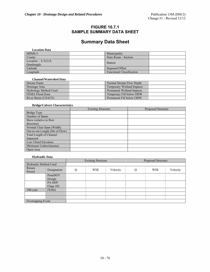
Chapter 10 - Drainage Design and Related Procedures Publication 13M (DM-2) Change #1 - Revised 12/12
10 - 76
FIGURE 10.7.1 SAMPLE SUMMARY DATA SHEET
Summary Data Sheet
Location Data
MPMS # Municipality County State Route - Section Location - U.S.G.S. Quadrangle Station
Latitude Segment/Offset Longitude Functional Classification
Channel/Watershed Data
Stream Name Normal Stream Flow Depth Drainage Area Temporary Wetland Impacts Hydrology Method Used Permanent Wetland Impacts FEMA Flood Zone Temporary Fill below OHW River Basin (USACE) Permanent Fill below OHW
Bridge/Culvert Characteristics
Existing Structure Proposed Structure Bridge Type Number of Spans Skew (relative to flow direction)
Normal Clear Span (Width) Out-to-out Length (Dir of Flow) Total Length of Channel Impacted
Low Chord Elevation Minimum Underclearance Open Area
Hydraulic Data
Existing Structure Proposed Structure Hydraulic Method Used Return Period Designation Q WSE Velocity Q WSE Velocity
PennDOT Design
PA DEP Chap 105
100-year FEMA Overtopping Event

Chapter 10 - Drainage Design and Related Procedures Publication 13M (DM-2) Change #1 - Revised 12/12
10 - 77
D. Abbreviated and Full H&H Reports. 1. Design Considerations Included in Drawings.
a. Backwater Computations. Backwater computations are required to determine the geometry of bridge openings. However, for some permits, these computations may be waived by the regulatory agency for one of the following flooding cases:
(1) The proposed bridge is a reconstruction project or an extension of the existing structure where the history of the existing structure and the scope of the proposed project can be utilized as justification to waive the computations. (2) The proposed bridge is a minor structure where the costly expenditure for the hydraulic report preparation is not warranted and where the existing field condition coupled with a sound engineering judgment can be utilized as a basis to determine the opening. (3) The backwater determination is of no value and the uniform flow condition is reasonably applicable to the proposed bridge.
However, in the above cases, the hydraulic analysis based on Manning's equation (refer to Section 10.3) should be indicated in the Hydrologic and Hydraulic Report. The provision for applying Manning's equation assuming uniform flow conditions in these cases should not be construed as the Department's acceptance of this formula as a valid method for sizing a bridge opening. It merely serves as a routine hydraulic record for those projects for which the comprehensive hydraulic analysis by the backwater computations is not warranted or is of no significance.
b. Temporary Drainage Facilities. The temporary stream crossing item and other temporary facilities shall be included in the Hydrologic and Hydraulic Report. The approximate length of time that it remains in the stream shall be indicated. If a temporary stream crossing is not required, a statement should be included on the plan in the report describing how traffic or construction equipment can be detoured without entering and disturbing the stream. All temporary facilities to facilitate the permanent structure construction shall be covered in the Report. Joint Agency Guidance developed by PennDOT and PA DEP related to evaluating and permitting temporary structures is included in Chapter 10, Appendix G. This guidance should be followed for permitting temporary structures. This guidance is in addition to meeting the design requirements for temporary crossings as specified in Chapter 18, Section 18.5 and Publication 15M, Design Manual, Part 4, Structures, Volume 1, Part A, Chapter 5. c. Occasional Flowage Easements. When designing a drainage structure, increases in headwater or backwater can be balanced against the structure size and cost. In fact, culvert or bridge design sometimes becomes an economic problem in which structure costs for various headwater elevations are balanced against the estimated costs of possible damage or inconvenience. In some cases, the cost of securing an occasional flowage easement (flood easement) for the structure can be significantly less than the additional expenses required to provide a larger structure. If the headwater pool created by the recommended size of the structure can result in apparent flood damages, an "occasional flowage easement" shall be provided for this structure. The "occasional flowage easement" shall be designated and indicated on the plans of the Hydrologic and Hydraulic Report and on other appropriate drawings as required. The use of an "occasional flowage easement" shall be limited to rural and/or other low real estate value areas. In all other areas (residential, commercial, industrial, etc.), the drainage structure should be designed to accommodate the flood discharges without creating increases in flood damages. To enable an appraiser to make a written report for the actual taking of "occasional flowage easements", the District Right-of-Way Administrator shall be furnished maps and/or drawings showing the maximum elevation of the headwater pool, the flood frequency (usually based on a 100-year flood) and duration data and other available pertinent information for the approved structure. If the flood duration data cannot be determined by means of an analytical method, it should be estimated on the basis of an

Chapter 10 - Drainage Design and Related Procedures Publication 13M (DM-2) Change #1 - Revised 12/12
10 - 78
extensive field investigation. In this case, it may be advisable to give an over-predicted rather than an under-predicted flood duration. For the purpose of making an economic analysis to determine the recommended size of the structure in the Hydrologic and Hydraulic Report, the cost of the "occasional flowage easement" used in the analysis may be estimated on the basis of an assumption that the property affected shall be flooded permanently and, therefore, determination of the flood duration data may be omitted. The preliminary cost estimate of the "occasional flowage easement" based on this assumption shall be made by the District Right-of-Way Administrator upon written request. The District Right-of-Way Administrator shall be furnished maps and/or drawings showing the maximum elevation of the design flood headwater pool, the extent of the easement required and other pertinent information as needed. The cost of the easement should be estimated by a qualified appraiser rather than by the designer who prepares the Hydrologic and Hydraulic Report. d. Fish Passage. Where a culvert is to be installed in a fishable stream, fish passage treatment should be provided in accordance with Section 10.10 and Section 10.11. e. Multi-Cell Structures. Concerning the minimum individual span width for multi-cell structures, each structure shall be evaluated on its own merit. After evaluating the upstream characteristic and debris problems that are anticipated, the minimum individual span width of a multi-cell structure shall be 4 m (14 ft). f. Alternate Structure Types. Where the Department's policy requires that alternate structure types be included for bidding in accordance with the alternate design, low cost bridge or short span bridge procedure, all alternate structures should be identified in the Hydrologic and Hydraulic Report. Separate hydraulic analysis should be developed for any alternate structure where the analysis included in the report cannot be reasonably applied to this alternate structure. In some instances, providing an "equivalent effective waterway" may be sufficient to demonstrate the hydraulic adequacy of an alternate structure. Adequate fish passage measures should be provided for the prime as well as all alternate types of structures. g. PS&E Construction and Structural Plans. For all waterway structures, the construction and structural plans to be submitted for PS&E approvals shall show: (1) the magnitude, return period, and water surface elevations for the design flood and the 100-year flood, if different from the design flood, (2) if available, the magnitude, water surface elevations and dates of occurrence of the flood of record, if greater than the 100-year flood, and (3) if required, the magnitude, return period, and water surface elevations for the overtopping flood. The waterway structures, including roadway encroachments, should be designed to minimize the flood hazards to properties by:
(1) Limiting backwater to a maximum of 0.3 m (1 ft) based on a 100-year flood unless where:
(i) Higher water levels can be tolerated with minimal damage or (ii) Mitigation is provided.
(2) Protecting against excessive backwater at crossings resulting from debris or ice blockage or extraordinary large floods by providing:
(i) Relief at or below the 100-year flood level by roadway overtopping or other practicable means or (ii) Bridge superstructure clearance above the 100-year flood elevation where relief is not provided.
h. FEMA Considerations. For any encroachment into the FEMA regulatory floodway which shall result in an increase of the water surface elevation during a 100-year flood, no permit may be issued by PA DEP unless documentation is obtained from the applicable municipalities certifying to the effect that

Chapter 10 - Drainage Design and Related Procedures Publication 13M (DM-2) Change #1 - Revised 12/12
10 - 79
the project is consistent with the local floodplain and storm water management programs. This documentation should be obtained by the Engineering District and included in the report. Where there is a need for revising the flood insurance study, the Engineering District should also coordinate with the municipality and FEMA to effect the necessary revision. If any hydrologic or hydraulic data used in the report deviates from the flood insurance study, the Engineering District Office should receive a written clarification or confirmation from FEMA.
2. Coordination with FEMA and Local Municipalities. All projects affecting waterways within National Flood Insurance Program (NFIP) study areas will follow the standard procedures for compliance with floodway regulations (such as, but not limited to, 44 CFR 65.3, 44 CFR 65.12, 23 CFR 650, 42 USC 50, 25 PA Code §105 and §106, and 12 PA Code §113). Different project scenarios require different interactions with FEMA and/or local Municipalities on the part of PennDOT to comply with the above regulations. Those scenarios are described below.
Scenario 1: If the proposed project is not located in a FEMA (detailed or approximate) study area.
PennDOT Requirements: No coordination with FEMA. Notify the local Municipality of a significant
encroachment, as defined in 23 CFR 650 A Section 650.105 (q), such as an interruption to emergency vehicle routes, or other significant risk.
Scenario 2: If the proposed project is located in a FEMA Approximate study area and does not cause
increases to the 100-year water surface elevations of the Proposed conditions model when compared to the Existing conditions model.
PennDOT Requirements: No coordination with FEMA is required. Send a courtesy copy of the H&H
Report to the local Municipality's Floodplain Manager.
Scenario 3: If the proposed project is located in a FEMA Detailed study area (with or without floodway) and does not cause increases to the 100-year water surface elevations of the Proposed conditions model when compared to the Existing conditions model, and one or more of the following occurs:
a. the hydrologic analysis produces different peak flow values than used in FEMA flood study
b. flow values are not provided by FEMA in its Flood Study
c. PennDOT's estimates of existing 100-year water surface elevations differ from the values reported in current effective FEMA studies
d. if a project is located in a detailed FEMA study area with a floodway and the proposed project will alter the floodplain or floodway boundaries
PennDOT Requirements:
If PennDOT's hydrologic analysis produced a different value for the 100-year peak flow from FEMA's, then both PennDOT's and FEMA's peak flow values should be included among the flow values used in the hydraulic models and report.
If PennDOT's estimates of existing 100-year water surface elevations differ from the values reported in current effective FEMA studies, the amount of the difference should be tabulated and briefly explained in the H&H report. See Chapter 10, Appendix C for more information about modeling.
No coordination with FEMA is required. The final H&H Report and modeling shall be shared with the local Municipality. The local municipalities responsible for the NFIP map can use PennDOT's data locally to supplement the existing FEMA data and to help the municipality implement their commitment under the NFIP and the PA Flood Plain Management Act (1978 Act 166) in order to regulate development in floodplain areas. It should be noted that PennDOT is not required to comply with local ordinances. The cover letter to the local municipality should include the

Chapter 10 - Drainage Design and Related Procedures Publication 13M (DM-2) Change #1 - Revised 12/12
10 - 80
following content:
i. An explanation that the purpose of the letter is to inform the municipality that PennDOT's analysis has produced results that differ from the current effective NFIP model. ii. A short explanation that highlights the differences. iii. A statement that PennDOT is not required to revise the NFIP map because the proposed project does not result in a regulated increase in the 100-year water surface elevation. iv. A statement that PennDOT is providing a copy of the analysis for consideration during the next regular update to the NFIP map. v. Where flow values are newly developed in the absence of FEMA flow values, the letter shall simply state that the information is provided for use by the municipality in fulfilling its obligations and responsibilities under the NFIP and PA Act 166 of 1978.
Scenario 4: If the proposed project is located in FEMA study area (Approximate, detailed without floodway, or detailed with floodway) and causes increases to the Proposed model's 100-year water surface elevations when compared with the Existing model's 100-year water surface elevations by any of the following:
a. by less than or equal to 1-foot in an approximate FEMA study area b. by less than or equal to 1-foot in a detailed FEMA study area when no fill will occur in the floodway c. by less than or equal to 1-foot in a detailed FEMA study area with no designated floodway
PennDOT Requirements: No coordination with FEMA is required unless there is a change to the
floodway geometry (then follow Scenario 5). PennDOT District will forward one copy of final Hydrologic and Hydraulic (H&H) Reports to the local Municipality to supplement the existing FEMA data and to help the Municipality implement their commitment under the NFIP and the PA Flood Plain Management Act. The cover letter to the Municipality shall include a statement that PennDOT is not required to revise the NFIP map and that PennDOT is providing a copy of the analysis for consideration during the next regular update to the NFIP map.
Scenario 5: If the proposed project is located in a FEMA study area (Approximate, detailed without
floodway, or detailed with floodway) and causes increases to the Proposed 100-year water surface elevations when compared with the Existing 100-year water surface elevations by any of the following:
a. by greater than 1-foot in an approximate FEMA study area b. by greater than 1-foot in a detailed FEMA study area if no fill will occur in the floodway c. by greater than 0.00-foot in a detailed FEMA study area if fill will occur in the floodway d. by greater than 1-foot in a detailed FEMA study area with no designated floodway PennDOT Requirements: A Conditional Letter of Map Revision (CLOMR) application is to be prepared
and sent to FEMA. A CLOMR does not revise an effective NFIP map. The FEMA MT-2 Forms 1, 2, and 3 and the final H&H Report and models must be submitted to FEMA along with the CLOMR fee. Coordination with the local Municipality and affected property owners must occur as prescribed in the MT-2 forms prior to submission of the CLOMR application to FEMA.
If the project will increase the 100-year flood elevation to a structure(s), PennDOT must certify that PennDOT will purchase and remove the structure(s) before FEMA can approve a CLOMR (see 44 CFR 65.12(a)(5)). For example, if the project is located in a FEMA detailed floodway (as in

Chapter 10 - Drainage Design and Related Procedures Publication 13M (DM-2) Change #1 - Revised 12/12
10 - 81
Scenario 5c) and a structure is inundated to a depth of 4 feet by the 100-year flood before the project is constructed, but will be inundated to a depth of 4 feet 2 inches after the project is constructed, that structure must be purchased and removed by PennDOT before the project is built. Certification that the structure(s) will be purchased and demolished is required before FEMA can approve the CLOMR.
No later than six months after completion of construction, a Letter of Map Revision (LOMR) is to be prepared and sent to FEMA as an official amendment to the effective NFIP map. A LOMR may change flood insurance risk zones, floodplain and/or floodway boundary delineations, planimetric features, and/or Base Flood (100-year) Elevations. The FEMA MT-2 Forms 1, 2, and 3 and the final H&H Report and models must be submitted to FEMA along with the LOMR fee. Coordination with the local Municipality and affected property owners must occur as prescribed in the MT-2 forms prior to submission to of the CLOMR request to FEMA.
The address for submitting H&H Reports to FEMA is:
Federal Insurance and Mitigation Division Director FEMA Region III 615 Chestnut Street, 6th Floor Philadelphia, PA 19106-4404
One copy of the transmittal letter will be sent to:
Chief, Floodplain Management Division Department of Community and Economic Development Keystone Building, 4th Floor Harrisburg, PA 17120
One copy of the transmittal letter will be sent to:
Bureau of Project Delivery Highway Delivery Division Highway Design and Technology Section Hydrology and Hydraulics Unit Keystone Building, 7th Floor 400 North Street Harrisburg, PA 17120
Figure 10.7.2 presents an example transmittal letter. Sources for additional information, guidance, and forms pertaining to NFIP maps include:
a. "Procedures for Compliance with Floodway Regulations", USACE, May 1990. b. FEMA's Internet site on flood hazard mapping (www.fema.gov).
INTENTIONALLY BLANK

Chapter 10 - Drainage Design and Related Procedures Publication 13M (DM-2) Change #1 - Revised 12/12
10 - 82
FIGURE 10.7.2 EXAMPLE TRANSMITTAL LETTER FOR H&H REPORTS
WITHIN AN IDENTIFIED FLOOD HAZARD ZONE ON A FEMA NFIP MAP
QQ-Return-Address
QQ-Date 1QQ County, 2QQ Township S.R. 3QQ, Section 4QQ Segment 5QQ, Offset 6QQ over 7QQ Final Hydrologic and Hydraulic Report NFIP Community: QQ-name / QQ-number / QQ-date Federal Insurance and Mitigation Division Director FEMA Region III 615 Chestnut Street, 6th Floor Philadelphia, PA 19106-4404 Dear Sir/Madame:
Enclosed for your use is one (1) copy of the final Hydrologic and Hydraulic report for the subject project. This project lies within an identified flood hazard zone on a FEMA National Flood Insurance Program (NFIP) Map.
The hydraulic analysis shows that the proposed project does not increase 100-year water surface elevations; therefore, PennDOT is not required by regulations to revise the NFIP Map.
DELETE THIS COMMENT. DELETE THE FOLLOWING PARAGRAPH WHEN IT DOES NOT APPLY. PennDOT's hydraulic analysis produced 100-year water surface elevations that differ from the values reported
in the current effective NFIP study. These differences are summarized and tabulated in the report. The analysis also shows that the proposed project causes NO increase in 100- year water surface elevations.
DELETE THIS COMMENT. DELETE THE FOLLOWING PARAGRAPH WHEN IT DOES NOT APPLY. PennDOT's hydrologic analysis shows that the 100-year peak flow has (increased/decreased) from the value
reported in the current effective NFIP study. Using the existing physical geometry, the effect of the change in 100-year peak flow on existing water surface elevations has been analyzed and tabulated in the report.
We have received both the Chapter 105 Water Obstruction and Encroachment Permit and the Pennsylvania State Programmatic General Permit (PASPGP) from the Pennsylvania Department of Environmental Protection for the subject project.
Should you have any questions, please contact QQ-name, District Regulatory Permit/H&H Coordinator at QQ-phone.
Sincerely,
QQ-Name District Executive Engineering District, QQnum-0
Enclosures

Chapter 10 - Drainage Design and Related Procedures Publication 13M (DM-2) Change #1 - Revised 12/12
10 - 83
FIGURE 10.7.2 (CONTINUED) EXAMPLE TRANSMITTAL LETTER FOR H&H REPORTS
WITHIN AN IDENTIFIED FLOOD HAZARD ZONE ON A FEMA NFIP MAP
QQ-District/QQ-Initials/Project cc: QQ-Name
Chief, Floodplain Management Division Department of Community and Economic Development Keystone Building, 4th Floor 400 North Street Harrisburg, PA 17120 QQ-Name Bureau of Project Delivery Highway Delivery Division Highway Design and Technology Section Hydrology and Hydraulics Unit Keystone Building, 7th Floor 400 North Street Harrisburg, PA 17120 Local Municipality/Municipalities District Executive Circulation and File Copies

Chapter 10 - Drainage Design and Related Procedures Publication 13M (DM-2) Change #1 - Revised 12/12
10 - 84
10.8 PROCEDURE FOR OBTAINING PERMITS FROM THE US COAST GUARD
The Commandant, US Coast Guard, Washington, DC, approves the plans and locations of bridges (including approaches, false work and cofferdams) across Navigable Waters of the United States, prior to the start of construction. The general procedure for obtaining permits from the US Coast Guard is described in this section. A. Navigable Waters of the United States.
1. The term "Navigable Waters of the United States" is construed to mean those waters of the United States, including the territorial seas adjacent thereto, the general character of which is navigable, and which, either by themselves or by uniting with other waters, form a continuous waterway on which boats or vessels may navigate or travel between two or more States or to or from foreign nations. A stream which otherwise conforms with the above definition would not change its navigable character because of the existence of natural or artificial obstructions such as falls, shallows, rapids, dams or bridges.
2. The Federal Government has the power to improve the navigable capacity of streams and declare such waters to be Navigable Waters of the United States in order to regulate the use thereof and navigation thereon. The erection of dams or other structures on navigable waters would not change their navigable character unless a clear intent to do so was manifested by Congress under its authority to regulate commerce among the States and foreign nations.
B. Jurisdiction of Coast Guard Districts. As indicated in Figure 10.8.1, there are three Coast Guard Districts with jurisdiction over the construction of bridges across the navigable waters in Pennsylvania. Applications for Permits shall be made to the Commander of the District in which the proposed bridge will be located. The addresses and zones of jurisdiction in Pennsylvania for these Districts are as follows: 1. Commander (aowb) Fifth Coast Guard District LANTAREA Federal Building 431 Crawford Street Portsmouth, VA 23704-5004 Tel: 757-398-6222 Zone of Jurisdiction: East of 79º W Longitude 2. Commander (obr) Eighth Coast Guard District 1222 Spruce Street St. Louis, MO 63103-2398 Tel: 314-539-3900, ext. 378 Zone of Jurisdiction: South of 41º N Latitude and West of 79º W Longitude 3. Commander (obr) Ninth Coast Guard District 1240 East 9th Street Cleveland, OH 44199-2060 Tel: 216-902-6085 Zone of Jurisdiction: North of 41º N Latitude and West of 79º W Longitude

Chapter 10 - Drainage Design and Related Procedures Publication 13M (DM-2) Change #1 - Revised 12/12
10 - 85

Chapter 10 - Drainage Design and Related Procedures Publication 13M (DM-2) Change #1 - Revised 12/12
10 - 86
Generally, streams in Pennsylvania that flow into the Atlantic Ocean are in the Fifth Coast Guard District; streams that flow into the Mississippi River are in the Eighth Coast Guard District; and streams that flow into the Great Lakes are in the Ninth Coast Guard District. An exception to the zones of jurisdiction as described above is found in the headwaters of the Allegheny and Beaver Rivers, navigable portions of which are in the Ninth Coast Guard District (above Latitude 41° N). Applications for bridge permits across these rivers shall be directed to the Eighth Coast Guard District. C. Navigable Waters in Pennsylvania Requiring Coast Guard Bridge Permits. As mentioned before, a permit shall be obtained from the Coast Guard for the construction of a bridge (including approaches, false work and cofferdams) across a Navigable Water of the United States. Although the general term "Navigable Waters of the United States" was previously defined, it is impossible to make a complete list of these waters in Pennsylvania because of the detailed research and inquiries that must go into each determination by the Commandant of the Coast Guard. A permit may be waived (subject to the Coast Guard's and/or FHWA's determination) for those bridges which cross non-tidal waters that are not used, susceptible to use in their natural condition, or susceptible to use by reasonable improvement as a means to transport interstate or foreign commerce. The administrative determinations made by each Coast Guard District for the Navigable Waters of the United States in Pennsylvania are as follows:
1. Eighth Coast Guard District (St. Louis). The approval and permit of the Commandant, US Coast Guard is required for bridges over the following named rivers in Pennsylvania within the Eighth Coast Guard District:
a. Allegheny River: Mouth to East Brady, Pennsylvania, Kilometer 115.87 (Mile 72.0) b. Monongahela River: Mouth to Kilometer 207.12 (Mile 128.7) c. Youghiogheny River: Mouth to Kilometer 31.06 (Mile 19.3) at West Newton, Pennsylvania d. Ohio River: The entire length e. Beaver River: Mouth to Kilometer 34.60 (Mile 21.5) f. Mahoning River: Mouth to upstream limits of Warren, Ohio, Kilometer 65.98 (Mile 41.0) g. Shenango River: Mouth to New Castle, Pennsylvania, Kilometer 7.56 (Mile 4.7)
All other navigable streams within this District are considered to be in the Advance Approval Category for bridges. In such cases, assume the clearances provided for high water stages and for the passage of drift are adequate to meet the reasonable needs of navigation.
2. Fifth Coast Guard District (Portsmouth). The Susquehanna River and Codorus Creek are the only waterways in the Fifth Coast Guard District Zone of responsibility in Pennsylvania which are in the advance approval category. All tributaries to the Susquehanna River and Codorus Creek are also included in this advance approval category. Except for the above waterways, no formal administrative determination has been made by the Commandant of the Coast Guard regarding the navigational status of the rivers in Pennsylvania within the Fifth Coast Guard District's zone of responsibility. Although the status of some reaches of the Delaware, Lehigh and Schuylkill Rivers and Chester Creek has not been officially determined by the Coast Guard, these waterways are generally considered as "navigable waters" of the United States and, therefore, a permit from the Coast Guard is required for any bridge across some reaches of these waterways. A bridge permit may also be required for any other streams within this District, the general character of which is navigable or which is actually navigated by boats or vessels.

Chapter 10 - Drainage Design and Related Procedures Publication 13M (DM-2) Change #1 - Revised 12/12
10 - 87
3. Ninth Coast Guard District (Cleveland). The approval and permit of the Commandant of the US Coast Guard is required for bridges over the following navigable waterways within the Ninth Coast Guard District:
a. Erie Harbor: Located on Lake Erie including the entire channel.
b. Elk Creek: From its mouth at Lake Erie near Lake City, Pennsylvania, upstream (south) approximately 762 m (2500 ft), to the head of the authorized Federal River and Harbor Navigation Improvement Project.
There are no Advance Approval Category waterways over which the Ninth Coast Guard District exercises jurisdiction in Pennsylvania. A bridge permit from the Coast Guard may also be required for any other stream within this District, the general character of which is navigable or which is actually navigated by boats or vessels.
D. Applications for Bridge Permits. To evaluate if a Coast Guard permit is required, make a determination using 23 USC 144 (h) based on information obtained in data gathering and through coordination with the Coast Guard as per 23 CFR 650, Subpart H, Sections 805 through 807. For any bridge which requires a permit from the Coast Guard, the application for the permit shall be filed by the Engineering District Office to the Coast Guard. The District Executive shall submit the following information for transmittal to the Coast Guard for the bridge permit:
1. A letter from the Department of Environmental Protection certifying that there is reasonable assurance that construction of the proposed structure does not violate the water quality standards of the Commonwealth of Pennsylvania.
2. Two copies of the Environmental Document (Categorical Exclusion, Environmental Assessment or Environmental Impact Statement).
3. A statement pertaining to the cost of the bridge as follows: a. Cost of bridge with navigational increment. b. Increase in cost attributable to added clearances provided for navigation.
4. A statement concerning the planned disposition of the existing bridge, if any. If an existing bridge not owned by the Department is to be removed, show consent of the owner for its removal.
5. An original and five copies of the following (size of 8.5 in × 11 in):
a. A map of the vicinity showing the location of the bridge site and the location of any wildlife and waterfowl refuges, recreation areas, public parks or historic sites in the vicinity or in the way of the bridge or its approaches. This map should also include an arrow indicating north, show other bridges in proximity to the proposed bridge and sufficient local characteristics to permit ready identification. The work site should be outlined in red. b. A plan of the bridge showing the bridge in both plan and elevation views. Outline the navigational opening(s) in red. Navigational clearances may be described as follows:
(1) The minimum horizontal clearance, normal to the axis of the navigational channel, between the faces of the piers or inside any protection works.
(2) The maximum vertical clearance that will be available at the highest point of the navigation span(s).
(3) The least clear height, with respect to the appropriate recognized datum at the site, of the lowest part of the superstructure of the navigation span(s) shall be clearly indicated.
Chapter 10 - Drainage Design and Related Procedures Publication 13M (DM-2) Change #1 - Revised 12/12
10 - 88
(4) The elevation of the lowest part of the superstructure should be shown at the channelward face of each pier, at the midpoint of the span and, in the case of a haunched bridge, 7.5 m (25 ft) channelward of each pier.
(5) Other related data to be shown as appropriate, including:
(a) Dimensions of the navigation channel. If stream is navigable from bank-to-bank, this may be omitted.
(b) Harbor lines, if established.
(c) Soundings and elevations, in meters (feet), with respect to the established government datum.
(d) The direction of the current (indicated by an arrow).
(e) The direction of true north.
(f) Where appropriate, vertical clearance should be shown above normal pool elevation and the 2% flowline elevation or, on a free-flowline river, above low water elevation and the 2% flowline elevation. The information on 2% flowline elevation may be obtained from the local Corps of Engineers' office.
Only those structural details necessary to illustrate the effect of the proposed structure on navigation should be shown. Drawings should be on 8.5 in × 11 in sheets; show a simple title block in the lower right-hand corner of each sheet. The title block should identify the Department, the bridge and the date of plans. The information required for the application of the Coast Guard Bridge Permit may be submitted to the Central Office, Bureau of Project Delivery at the time of the waterway submission or at any other appropriate time. As the required information may vary with individual situations, the District Executive is authorized to contact the appropriate Coast Guard District for information on specific navigation requirements or other particular requirements prior to preparing the materials required for the formal application. However, copies of all correspondence on this matter should be forwarded to the Central Office, Bureau of Project Delivery for information. For any bridge to be constructed over a stream in the Advance Approval Category, a formal application to the Coast Guard is not required. However, since the Coast Guard recommends that they be advised whenever a bridge is planned over a stream of any consequence, it is suggested that the Engineering District Office forward one set of the preliminary bridge drawings to the Coast Guard for information for those bridges to be constructed under the Advance Approval Category. It would be advisable to obtain a letter of no objection from the Coast Guard as a record. The need for pier protection from possible ship collision should be evaluated for all bridge piers placed in navigable waterways with substantial commercial navigational traffic.
10.9 PROCEDURE FOR OBTAINING PERMITS FROM THE US ARMY CORPS OF ENGINEERS This section describes the Department's procedures for obtaining permits from the US Army Corps of Engineers (USACE) for highway improvement projects. It also serves as a general guide to various USACE regulations, including the Section 404 Permit, the Section 10 Permit, and the Pennsylvania State Programmatic General Permit (PASPGP). It is the Pennsylvania Department of Environmental Protection's (PA DEP's) responsibility to coordinate. To avoid confusion and duplication of effort, PA DEP, in conjunction with the USACE, has developed a Joint Permit

Chapter 10 - Drainage Design and Related Procedures Publication 13M (DM-2) Change #1 - Revised 12/12
10 - 89
Application (JPA) for activities in, along and across waters (and wetlands) of the Commonwealth. Once a joint permit is submitted to PA DEP, it is considered on record for both state and federal agencies. The USACE shall receive a copy of the waterway submission from PA DEP thru the JPA process. Upon receipt of the submission, the USACE shall act on confirmation of the applicability of the nationwide permit or process an individual Department of the Army permit (USACE Section 404 permit). The most common type of USACE permits applicable to highway projects is the Section 404 Permit regarding discharges (placements) of dredged or fill material into waters of the United States. This type of permit is conditionally exempted for maintenance, including emergency reconstruction of bridge abutments or approaches and transportation structures and for temporary sedimentation basins. For projects involving emergency reconstruction, there are different funding requirements between federal sources and 100% state sources. For federal-aid procedures, refer to 23 CFR Part 668; for state procedures, refer to the 4 PA Code § 67. A "nationwide permit" has been issued by USACE to permit certain discharges of fill material into waters of the United States throughout the Nation. The specific categories of discharges of fill material covered in the nationwide permit, the validity of which is contingent upon the issuance of a Section 401 water quality certification by the State, are indicated in 33 CFR Part 330. The issuance of a water obstruction permit by PA DEP also constitutes approval for the water quality certification. Among highway activities covered in this nationwide permit are:
1. Certain repair, rehabilitation or replacement of the structure and fill which does not deviate from the plans of the original structure or fill.
2. Certain outfall structures and associated intake structures.
3. Certain bank stabilization activities less than 150 m (500 ft) in length and less than an average of 2.5 m3 of fill material per running meter (1 yd3 of fill material per running foot) along the bank.
4. Certain highway crossings that involve less than 150 m3 (200 yd3) of fill material placed in waters.
5. Certain fill placed for bridges across Navigable Waters of the United States provided a permit is obtained from the US Coast Guard.
6. Certain discharges of fill material that do not exceed 7.5 m3 (10 yd3). 7. Federal-aid projects classified as "categorical exclusion". 8. Discharge of concrete into tightly sealed forms or cells.
9. Certain activities performed at a location above the headwaters of the waters of the United States. All USACE's Districts in Pennsylvania have accepted 8 km2 (3 mi2) of drainage area as a general rule-of-thumb for determination of the headwaters.
The USACE is responsible for administering Federal regulations under two separate authorities: Section 404 of the Clean Water Act (CWA) of 1972 and Section 10 of the Rivers and Harbors Act of 1899. A. Section 404. Under the authority of the Section 404(b)(1) Guidelines of the CWA, the USACE exercises jurisdiction over the waters (both navigable and otherwise) of the United States. Section 404 applies to the disposal of dredged or fill material into lakes, rivers and wetlands. Federal regulations on the USACE's permit program are contained in 33 CFR Parts 320-331. Accordingly, the Department shall obtain approval from the USACE in the form of a Section 404 Permit for all proposed encroachments (not including bridges) involving the placement of dredged or fill materials in the waters of the United States in Pennsylvania. Bridges are not included because placement of pilings for linear projects, such as bridges, generally does not have the effect of a discharge of fill material. All Section 404 permit applications shall comply with the Guidelines in order for the Permit to be issued. The USACE is authorized to determine whether a project complies with the Guidelines.

Chapter 10 - Drainage Design and Related Procedures Publication 13M (DM-2) Change #1 - Revised 12/12
10 - 90
Section 404 permits are issued through the four USACE Districts which exercise jurisdiction in Pennsylvania (see list below). Some nationwide and regional permits have been issued to cover specific types of discharges. Permit applicants shall provide sufficient information to complete a 404(b)(1) evaluation, which is prepared by the permitting office. The final determination of acceptability of any proposed discharge of dredged or fill material considers the probable impact, including cumulative impacts of the proposed discharge, on the public interest. The CWA directs that 404(b)(1) Guidelines be promulgated by the Administrator of the USEPA in conjunction with the USACE. B. Section 10. In addition to dredged or fill discharge permits, the USACE also issues permits for any structures or work that impact the course, capacity, or condition of a navigable water of the United States under Section 10 of the Rivers & Harbors Act of 1899 (33 US Code (USC) Section 403). The Section 10 permit program is managed by the same USACE Districts as the Section 404 permits. Section 10 and Section 404 permits are typically handled jointly. The USACE coordinates Section 10 permits with the US Coast Guard, which issues a notice to navigation. C. Regional General Permit. The USACE, in coordination with PA DEP, administers a Regional General Permit known as the Pennsylvania State Programmatic General Permit (PASPGP). The PASPGP is a federal CWA, Section 404 Permit for various construction activities involving the discharge of dredge and fill material into waters of the United States. In most cases, a PASPGP can be issued by PA DEP or a county conservation district (with approved Chapter 105 water obstruction and encroachment permits). The validity of the PASPGP is contingent upon the issuance of a Section 401 Water Quality Certification (WQC) by the Commonwealth. The PASPGP incorporates federal and state permitting standards in one process, and thereby eliminates the need for dual and often redundant permitting procedures. This permit provides a coordinated approach to environmental protection. It divides regulated activities into the following three categories based on the size of the activity and compliance with state and federal permit review standards:
1. Category 1. These activities are not forwarded to the USACE for review and can normally be processed by the appropriate PA DEP regional office or delegated county conservation districts without the need for additional federal review. They include:
a. Activities waived at Chapter 105, Section 105.12 (except waiver #1, #2, and #14); and b. Activities authorized by a general permit (except for the gravel removal portion of the GP-3 and GP-15).
2. Category 2. These activities are published in the Pennsylvania Bulletin for public comments and as notice to the federal agencies, and can normally be processed by the appropriate PA DEP regional office or delegated county conservation districts without the need for additional federal review. They include:
a. Activities impacting less than one acre of wetland and other bodies of water; and b. Activities impacting less than 76 m (250 ft) of stream.
3. Category 3. These activities are reviewed individually by the USACE and PA DEP to ensure compliance with the terms and conditions of PASPGP. They include:
a. Activities impacting wetlands within the 14-county range of the bog turtle; b. Activities impacting more than 76 m (250 ft) of stream; c. Activities involving dams, weirs, fill or stream channelization in the Juniata and Susquehanna Rivers; and d. Activities in French, LeBoeuf, Muddy, Conneauttee Creeks or Conneaut Outlet.
Procedurally, the USACE evaluates Category 3 applications, and either determines that the proposed action qualifies under PASPGP, or requires an individual 404 permit review.

Chapter 10 - Drainage Design and Related Procedures Publication 13M (DM-2) Change #1 - Revised 12/12
10 - 91
4. Non-Qualifying Activities for Authorization. The following activities do not qualify for authorization under PASPGP, and require separate Section 404 and Chapter 105 authorizations, processed by the USACE and PA DEP:
a. Activities impacting more than one acre of water or wetlands; and b. Activities in the following waterbodies:
• Delaware River • Beaver River • Little Beaver River • Mahoning River • Monongahela River • Ohio River • Lake Erie and portions of the: • Schuylkill River • Lehigh River • Youghiogheny River • Allegheny River • Kiskiminetas River • Ten Mile Creek
D. Chapter 105/PASPGP General Permit Registration Form. The USACE, in coordination with PA DEP, uses a registration process for a Chapter 105/PASPGP General Permit. The registration process incorporates federal and state permit application requirements to facilitate the concurrent issuance of state and federal permits through one application. General permit registrations require submittal of the following items: 1. Project sketch plan 2. Project location information 3. Consultant information 4. Threatened and endangered species reviews. The registration package also includes a single and complete project screening process developed to assist the applicants, county conservation districts and PA DEP in determining that all environmental impacts related to the project have been evaluated, minimized and properly permitted. The permit registration process allows the permit applicants, as well as PA DEP and delegated county conservation districts, to ensure that projects meet the requirements of Chapter 105 and PASPGP. The General Permit Registration package is available on PA DEP's website, from Chapter 105 delegated county conservation districts and from PA DEP regional offices. For copies of PASPGP, contact the Baltimore District Corps of Engineers, Pennsylvania Section, (see address below) or visit the USACE website. For general information on the PASPGP process, contact one of the six PA DEP Regional Offices or the Division of Waterways, Wetlands and Erosion Control. E. Nationwide Permit (NWP). The NWP program is used when PASPGP cannot be used. The NWP program includes a notification provision that requires the following agencies to be contacted:
1. The US Fish and Wildlife Service (USF&W) and also National Marine Fisheries Service (NMFS) in the Coastal Zone Management (CZM) areas, regarding the presence of endangered or threatened species or critical habitat areas affected by the project.
2. The Pennsylvania Historical and Museum Commission (PHMC) regarding the presence of any historic properties affected by the proposed project.
Chapter 10 - Drainage Design and Related Procedures Publication 13M (DM-2) Change #1 - Revised 12/12
10 - 92
Refer to 33 CFR Part 330 and current Department directives for a complete listing of the specific categories of discharge of fill material covered in the NWP. F. Agency Coordination Meeting. The USACE is one of the Federal environmental resource agencies that participates in the Department's Agency Coordination Meeting (ACM) process. In this capacity, the USACE participates fully in the Department's ACM process, as described in Publication 10, Design Manual, Part 1, Transportation Program Development and Project Delivery Process, Chapter 3. Coordination with the USACE is also undertaken via agency coordination letters. G. USACE Districts. As indicated in Figure 10.9.1, there are four USACE Districts which exercise jurisdiction in Pennsylvania. They are:
1. US Army Corps of Engineers, Baltimore District Attention: CENAB-OP-R P.O. Box 1715 Baltimore, MD 21203-1715 2. US Army Corps of Engineers, Buffalo District Attention: CELRB-CO-SR 1776 Niagara Street Buffalo, NY 14207-3199 3. US Army Corps of Engineers, Philadelphia District Attention: CENAP-OP-R 100 Penn Square East 2nd and Chestnut Street Philadelphia, PA 19107-3390 4. US Army Corps of Engineers, Pittsburgh District Attention: CELRP-OP-F Federal Building 1000 Liberty Avenue Pittsburgh, PA 15222-4186
Figure 10.9.1 shows the boundaries of the Civil Works Districts. Note that the boundaries of the Pittsburgh, Baltimore, and Buffalo Civil Works Districts do not coincide with their Regulatory Districts. The Pittsburgh Regulatory District includes those streams draining into the Potomac River and that are located in the Baltimore Civil Works District. Also, the Pittsburgh Regulatory District includes Erie and Crawford Counties and those streams draining into Lake Erie; these are all located in the Buffalo Civil Works District. Verify in advance with the USACE about which District above has regulatory jurisdiction. H. Navigable Waters in Pennsylvania Requiring USACE Permits. A permit shall be obtained from the USACE for excavations, fills and construction of any structures (exclusive of bridges) in Navigable Waters of the United States. The administrative determinations made by each USACE District for the Navigable Waters of the United States in Pennsylvania are as follows:
1. Philadelphia District: The navigable waters in the Philadelphia District where permits are required are: a. All tidal waters and their tributaries to the head of tide b. Delaware River-----Delaware State Boundary to Hancock, New York and beyond c. Lehigh River--------114 km (71 mi) to the S.R. 0940 Bridge in Carbon County d. Manayunk Canal---3.2 km (2 mi) from Flat Rock Dam to Lock Street, Manayunk e. Schuylkill River----177 km (110 mi) to Port Carbon Section 10 permits are required for all construction activities in the above waters.
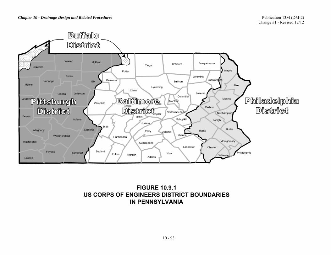
Chapter 10 - Drainage Design and Related Procedures Publication 13M (DM-2) Change #1 - Revised 12/12
10 - 93

Chapter 10 - Drainage Design and Related Procedures Publication 13M (DM-2) Change #1 - Revised 12/12
10 - 94
2. Baltimore District: The Baltimore District exercises jurisdiction over the Susquehanna River from its mouth upstream as far as Lock Haven, Pennsylvania on the West Branch and Athens, Pennsylvania on the North Branch. The only tributary to the Susquehanna River over which the District exercises jurisdiction is Codorus Creek. 3. Pittsburgh District: The navigable waters in the Pittsburgh District, where permits are required, are the Ohio, Allegheny, and Monongahela Rivers, and their respective tributaries, as listed below (with jurisdiction in kilometers (miles) above mouth in parentheses):
a. Ohio River and Tributaries.
1. Ohio River (head to Ohio State Boundary) 2. Chartiers Creek (3.06 km (1.9 mi)) 3. Beaver River (Entire Length) (34.60 km (21.5 mi)) 4. Mahoning River (Tributary of Beaver River) (mouth to Ohio State Boundary) 5. Shenango River (Tributary of Beaver River) (2.90 km (1.8 mi)) 6. Raccoon Creek (2.90 km (1.8 mi)) 7. Little Beaver River (mouth to Ohio State Boundary)
b. Allegheny River and Tributaries.
1. Allegheny River (mouth to New York State Boundary) 2. Kiskiminetas River (43.13 km (26.8 mi)) 3. Conemaugh River (Tributary of Kiskiminetas River (83.20 km (51.7 mi)) 4. Crooked Creek (2.41 km (1.5 mi)) 5. Mahoning Creek (2.25 km (1.4 mi)) 6. Redbank Creek (2.41 km (1.5 mi)) 7. Clarion River (144.84 km (90.0 mi)) 8. Tionesta Creek (0.48 km (0.3 mi))
c. Monongahela River and Tributaries.
1. Monongahela River (mouth to West Virginia State Boundary) 2. Youghiogheny River (50.21 km (31.2 mi)) 3. Ten Mile Creek (4.35 km (2.7 mi)) 4. Cheat River (5.47 km (3.4 mi))
d. Lake Erie-------Ohio State Boundary to New York State Boundary. The entire length of Lake Erie
is considered navigable for work below elevation 573.4.
4. Buffalo District: The navigable waters in the Buffalo District where the permits are required are: a. Erie Harbor-----Located on Lake Erie (includes entrance channel) b. Elk Creek-------Authorization Federal Project Note: For projects in Pennsylvania, the Buffalo District has delegated its authority for regulatory permits to the Pittsburgh District. Note that the provisions for permit requirements for the above listed waterways merely represent the views of the Department of the Army since jurisdiction of the United States can be conclusively determined only through judicial proceedings. Also note that the administrative determination of the navigable waters made by the USACE differs from that made by the US Coast Guard in many cases. I. USACE Water Resources Development Projects. Figure 10.9.1 identifies the boundaries of the four USACE Districts with jurisdiction in Pennsylvania. Approvals for work affecting a USACE project shall be obtained from the District Engineer of the appropriate USACE District.
Chapter 10 - Drainage Design and Related Procedures Publication 13M (DM-2) Change #1 - Revised 12/12
10 - 95
J. Application for Permits from the USACE. As indicated in Section 10.9, the USACE shall receive a copy of the waterway submission from PA DEP thru the Joint Permit Application process. Upon receipt of the submission, the USACE shall act on confirmation of the applicability of the nationwide permit or process an individual Department of the Army permit (USACE Section 404 permit). Whenever an individual USACE permit is required, it should be prepared and submitted through the JPA2 Expert System. The standard application form, as indicated in 33 CFR 325 (ENG Form 4345, "Application for Department of the Army Permit"), is to be prepared and submitted to the USACE. The application form is to include a complete description of the proposed activity including necessary drawings, sketches, or plans sufficient for public notice; the location, purpose, and need for the proposed activity; scheduling of the activity; the names and addresses of adjoining property owners; the location and dimensions of adjacent structures; and a list of authorizations required by other federal, interstate, state, or local agencies for the work, including all approvals received or denials already made. The Joint Permit Applications are generally submitted after the National Environmental Policy Act (NEPA) or other environmental documents have been approved and the projects are in final design. This practice may not be considered effective for complex projects since the processing of the USACE permits during the final design stage may not provide sufficient lead time to meet the desired letting schedules. For these projects, the USACE permit action should be initiated concurrently with the NEPA process. The recommended procedure for the time merger of these actions is indicated in the following item. K. Advance Processing of Department of the Army Permit. The required permit action, as to whether or not the proposed highway fill activities are subject to an individual USACE permit, should be determined during the Engineering and Environmental Scoping Field Views or at a time soon afterward. This determination should be completed by the Engineering District before an environmental document is prepared. If it is determined that an individual USACE permit is required and that an advance processing of the permit during the NEPA process is recommended, the Engineering District should submit the necessary information required for processing the permit application to the Bureau of Project Delivery in accordance with the following timings based on the applicable environmental procedures indicated: 1. Environmental Impact Statement (EIS):
a. Single or Preferred Build Alternative Recommended. Submit the Section 404 information as soon as the draft EIS is approved for distribution. b. Multiple Build Alternatives Without Preferred Build Alternative Recommended. Submit the Section 404 information after the pre-final EIS identifying a selected alternative is reviewed by the FHWA Division and submitted to the FHWA Regional Office, but before the final EIS is approved.
2. Environmental Assessment (EA):
a. Single or Preferred Build Alternative Recommended. Submit the Section 404 information as soon as the EA is approved for availability. b. Multiple Build Alternatives Without Preferred Build Alternative Recommended. Submit the Section 404 information after the revised EA is prepared, but before the Finding Of No Significant Impact (FONSI) is approved.
3. Categorical Exclusion (CE). Submit the Section 404 information as soon as the CE is approved and final design is initiated, preferably before the hydrologic and hydraulic report is submitted for a waterway approval.
INTENTIONALLY BLANK

Chapter 10 - Drainage Design and Related Procedures Publication 13M (DM-2) Change #1 - Revised 12/12
10 - 96
If an advance processing of the USACE permit during the NEPA process stage is recommended, the following information shall be submitted by the Engineering District to the Bureau of Project Delivery for processing the permit:
• Completed ENG Form 4345, "Application for Department of the Army Permit". • Two copies of the environmental documents, as required.
• One set of original 8.5 in × 11 in drawings and five sets of the prints of the same, showing all pertinent
features of the design layouts as well as those of all applicable and practical alternates of the temporary construction facilities.
For Department projects, the District Executive signs the application for a USACE permit. However, for municipal projects using Federal-aid funds, the Engineering District Office shall obtain from the applicable municipal authority and, after their review, submit to the Bureau of Project Delivery the above specified information including the completed permit application form (ENG Form 4345) signed by an appropriate municipal official. Advancing the USACE permit submissions in the NEPA process stage requires that bridge, hydraulic and roadway design engineers be involved in the development of project concepts and continue to be involved as the concepts are refined. Certain designs should be prepared when details are needed to respond to the environmental and related engineering concerns raised as part of the NEPA process as to supply adequate information for the USACE permit applications. Detailed engineering design may not be required for the purpose of preparing the information required for submitting a permit application. Available information on location, fill quantities and facility design should be sufficient to focus on major permit issues. Additional detailed information may always be supplemented, as needed, after a permit application is submitted. A USACE Section 404 permit submission should be prepared to cover the entire project limits for which an environmental document has been developed. For a highway project involving both individual and nationwide permit activities, a single USACE permit submission should be developed to cover all of these activities. Pertinent information should be included in the submission to identify as to which type of the permit action (individual or nationwide permit) will be applicable to each specific location of the fill activity. In this case, the Engineering District should obtain from the PA DEP Regional Office a water quality certification covering all fill activities for the entire highway project unless all of the activities are covered by the PA DEP water obstruction permits. L. Application for Approvals for Work in USACE Water Resources Projects Areas. The information required to obtain approval from the USACE for proposed work affecting a USACE water resources project area may vary with the nature of the project and/or the USACE District in which it is located. In many cases, the USACE will not grant an official approval until the final construction and structural drawings are developed. However, in some cases, the USACE may grant the approval based on a submission of the Hydrologic and Hydraulic Report. For any proposed work which may affect the USACE water resources facilities, the District Executive may submit the Hydrologic and Hydraulic Report directly to the USACE for approval or comments. Upon receipt of the approval or comments from the USACE, the District Office shall take further actions that are required, if any, at the time the waterway approval is issued or at any appropriate time as deemed proper. It is the District Executive's responsibility to coordinate with the local flood control or water resources authorities, if necessary. If the proposed work involves occupation of lands acquired by the Federal Government or alteration of the USACE facilities, a consent agreement shall be obtained from the USACE. It is the District Executive's responsibility to obtain the consent agreement directly from the USACE. In general, the consent agreement can be granted from the USACE only subsequent to the development of final plans.

Chapter 10 - Drainage Design and Related Procedures Publication 13M (DM-2) Change #1 - Revised 12/12
10 - 97
M. Preliminary Consultation with the USACE. The District Executive is authorized to contact the USACE for a preliminary consultation for the proposed work involved. The preliminary consultation may often be necessary in order to avoid the unnecessary expense of preparing plans for work for which none are required, or for preparing materials that do not meet the requirements of the USACE. Copies of all correspondence with the USACE should be forwarded to the Central Office, Bureau of Project Delivery for information. 10.10 CHANNEL CONSTRUCTION INVOLVING FISHABLE STREAMS A. Design Procedures. In order to give full consideration to the effects of channel construction on aquatic habitat, the following items shall be made part of the design procedures:
1. The stream affected shall be checked as to its inclusion in the stockable warm water and trout streams list. The stream of interest shall also be checked for inclusion on PFBC's list of Pennsylvania Stream Sections that Support Wild Trout Reproduction. PFBC updates its list annually, which is available through its website. PFBC shall be consulted if there is any question regarding its applicability. If the stream is on the list or is a private fishable stream, every effort should be made to avoid any channel encroachment caused by the highway section.
2. Where stream relocation is necessary, consideration should be given for the seeding of all disturbed areas, using rip rap for slope protection at locations where severe bank erosion would occur and placing stone deflectors or gabions (stone-filled wire baskets) for channel bottom protection to aid restoration of fish habitat. The relocated channel should bear resemblance to a natural stream having meandering alignment, varied stream widths, pools, chutes, boulders, etc. Sub-channels with an elevated floodplain should be provided (see Figure 10.10.1), if the new channel is wider than the existing one to accommodate flood discharges.
3. For stream relocation where excessive turbidity during construction shall affect fish life, consideration should be given to using a temporary channel for stream divergence.
4. When existing channels must be widened to provide for the design flood discharge, bench widening design should begin at the edge of stream 0.3 m (1 ft) (or more) above the stream bed whenever normal flow conditions permit (see Figure 10.10.1).
If the normal flow stream depth is greater than 0.3 m (1 ft), then the District Office should make a recommendation as to the depth of bench as part of the Hydrologic and Hydraulic Report submission. The depth indicated should be such as to preclude extreme channel widening. All disturbed areas should be seeded. The application of this design procedure should reduce the problem of construction equipment encroaching into the natural channel. In addition, the existing channel acts as a sub-channel for the passage of fish during low flow periods.
5. A low flow fish passage treatment, as indicated in Section 10.11, should be provided in a culvert to maintain a minimum flow for fish passage. Follow BD-632M unless specific project coordination with PFBC is required.
6. To further reduce stream turbidity and the destruction of fish habitat during construction, one of the following or similar types of stream crossings shall be used:
a. If the normal flow stream depth is greater than 0.3 m (1 ft), a battery of pipes with rock material in the embankment should be provided. These pipes should be of adequate strength to sustain embankment and vehicular loadings and of sufficient capacity (hydraulic computations necessary) to pass normal flow discharge with due consideration given to backwater effects. b. If the stream bed is of earth or erodible material and the normal flow stream depth is less than 0.3 m (1 ft), a layer of rock approximately 0.3 m (1 ft) in depth by 6.0 m (20 ft) in width should be provided. The above types of stream crossings are not all-inclusive. Other types of crossings may be considered. In every case, however, the Engineering District Office should make a recommendation as to the type and location of the stream crossing as part of the Hydrologic and Hydraulic Report submission.

Chapter 10 - Drainage Design and Related Procedures Publication 13M (DM-2) Change #1 - Revised 12/12
10 - 98

Chapter 10 - Drainage Design and Related Procedures Publication 13M (DM-2) Change #1 - Revised 12/12
10 - 99
B. No Construction Crossing. The following condition does not require a constructed crossing. If the stream bed is rock or non-erodible material and normal flow stream depth is less than 0.3 m (1 ft), a designated stream crossing should be made at the time of construction at the job site. This requirement for the temporary stream crossing is also applicable to non-fishable streams:
1. When existing channels are to be cleaned, a clam bucket, drag line or other types of construction equipment capable of working outside of the existing channel should be specified in the proposal to lessen the effects of the construction operation.
2. As indicated in Section 10.5, PFBC generally requires that no work is to be done in the stocked trout stream between March 1 and June 15. In the event a waiver of this restriction period is necessary, proper justifications, as required in Section 10.5, shall be provided.
C. Plan Requirements. Items in Section A above, with the exception of Item 1, shall be included in the plans of the Hydrologic and Hydraulic Report submission. In addition, they shall be designated on the final construction plans and included as part of the drawings and contract proposal. 10.11 LOW FLOW FISH PASSAGE THROUGH HIGHWAY CULVERTS A. Purpose. The purpose of this Section is to provide general guidance regarding the design of economical and functional low flow fish passage systems through highway culverts. B. Background. For culvert locations on streams with continuous flow, the ability to accommodate migrating and resident fish is an important design consideration. Excessive velocity, inadequate water depth, and high outlet elevations are the most frequent causes of fish passage problems. Culverts should be designed to simulate the natural stream bottom conditions by maintaining desirable flow depths and velocities. Constructing depressed culverts with baffles will help to simulate natural conditions by promoting the deposition and retention of stream bed material inside the culvert. The stream bed material between the baffles will increase the roughness coefficient of the culvert bottom, which helps to maintain the minimum flow depth and reduce velocities. Baffles or weir plates have been added for this purpose. Detailed guidelines for the design of baffle systems are provided apart from the description of other fish passage methods. C. Policy/Procedure.
1. Arrangements for fish passage should be provided in culverts in streams having continuous flow.
2. The Hydrologic and Hydraulic Report shall contain information as to whether the stream flow is continuous or intermittent. The report shall contain all necessary information to support the choice of providing or not providing the fish passage through the culvert.
3. The proposed fish passage arrangements shall be indicated on the plans for the proposed culvert and be designed in accordance with BD-632M.
D. Design Guidelines.
1. The normal flow depth at any point in the culvert may vary from 0.08 m to 0.2 m (3 in to 8 in) depending upon the species and size of fish, but in any case, it shall not be less than 0.08 m (3 in).
2. A stable condition is required at the inlet and outlet ends of the culvert for a good fish passage system. Choked rip-rap or similar measures should be provided at the inlet and outlet ends of the culvert.
3. The selection of the type (see E below) of fish passage depends upon the conditions of the stream site, ease of installation, and maintenance.

Chapter 10 - Drainage Design and Related Procedures Publication 13M (DM-2) Change #1 - Revised 12/12
10 - 100
E. Fish Passage Methods/Alternates.
1. Culverts with Fish Baffles (see Figures 10.11.1 and 10.11.2). This section provides guidance to designers on the hydraulic properties of culverts with baffles, configured according to Publication 218M, Standards for Bridge Design, Drawing BD-632M titled, "Standard, R.C. Box Culvert." BD-632M provides miscellaneous details for stream grades less than or equal to 4 percent and for grades greater than 4 percent. Two methods of modeling culverts with fish baffles are provided as follows:
a. Standard Method. The standard method represents the most simplified method of modeling culverts and requires the following:
(1) Box culverts with fish baffles designed in accordance with BD-632M are to be modeled assuming that the 0.3 m (1 ft) depression below the natural stream bed elevation is filled in with sediment. For example, a 3.0 m × 1.8 m (10 ft × 6 ft) culvert opening depressed 0.3 m (1 ft) in accordance with BD-632M should be modeled with a 3.0 m × 1.5 m (10 ft × 5 ft) hydraulic opening. (2) The Manning's n-value for the bottom of the hydraulic opening should be assumed to be the Manning's n-value for the natural channel material of the stream and the Manning's n-value for the sides and top of the culvert should be for the material of the culvert. (3) This modeling approach represents culverts filled with sediment between the baffles up to the depressed depth and can be applied to culverts with fish baffles under any flow condition.
Figure 10.11.1 is a graphic representation of the standard method for modeling the hydraulics of a depressed culvert. b. Alternate Method. An alternate method of modeling culverts with fish baffles has been developed through research conducted by FHWA in the 1970's. Details of the research are contained in the publication, Design Consideration and Calculations for Fishways Through a Box Culvert by R. M. Chang and Jerome M. Norman. This alternate method involves the use of special fish baffle Manning n-values in conjunction with modeling the full opening of the culvert. The assumption is that all sediment will be flushed from the culvert from high stream velocities leading up to the critical event. In many cases, this approach will result in a more hydraulically efficient culvert than the standard method for the full flow condition. The use of special fish baffle Manning's n-values and full opening of the culvert requires the following:
(1) Proof that the culvert is flowing full for selected design events. (2) Consideration of roadway overtopping which may occur before the culvert flows full. (3) Downstream tailwater submergence which may reduce velocities in the culvert. (4) D50 of streambed material to determine critical velocity to flush the sediment from the culvert. (5) Velocity through the culvert during design events to determine if sediment is removed from the culvert. (6) The hydraulic opening modeled is the full opening.
Table 10.11.1 and Table 10.11.2 present Manning's n-values for the alternate method for culverts with fish baffles for slopes greater than 4 percent and for slopes less than or equal to 4 percent. Figure 10.11.2 is a graphic showing the alternate method for modeling culvert hydraulics. Because of the complexities in using the special fish baffle n-values, the alternate method of modeling culverts with fish baffles may be used only in special circumstances with approval from the Bureau of Project Delivery, Highway Delivery Division, Highway Design and Technology Section, Hydrology and Hydraulics Unit.

Chapter 10 - Drainage Design and Related Procedures Publication 13M (DM-2) Change #1 - Revised 12/12
10 - 101
FIGURE 10.11.1 DEPRESSED CULVERT WITH FISH BAFFLES
USING THE STANDARD METHOD
FIGURE 10.11.2 DEPRESSED CULVERT WITH FISH BAFFLES
USING THE ALTERNATE METHOD
Road Profile
Depressed depth filled with sediment
Culvert Invert Depressed 300 mm (1’)
Hydraulic Opening 3000 mm span x 1500 mm rise
(10’ span x 5’ rise)
Manning’s n for bottom based on natural channel material
Manning’s n for sides and top based on culvert material (concrete)
1800 mm (6’) Rise
3000 mm (10’) Span
Bottom of Streambed
Road Profile
Assumed sediment washes out of baffles Culvert Invert Depressed
300 mm (1’) and baffled
Hydraulic Opening 3000 mm span x 1800 mm rise
(10’ span x 6’ rise)
Manning’s n for entire culvert based on tables provided for the alternate method
1800 mm (6’)
3000 mm (10’)
Bottom of Streambed
NOTE: Using the Alternate Method must be approved by Bureau of Project Delivery, Highway Delivery Division, Highway Design and Technology Section, Hydrology and Hydraulics Unit.

Chapter 10 - Drainage Design and Related Procedures Publication 13M (DM-2) Change #1 - Revised 12/12
10 - 102
TABLE 10.11.1 (METRIC) MANNING'S "n" VALUES FOR ALTERNATE METHOD OF MODELING BOX CULVERTS WITH FISH BAFFLES
AND SLOPE > 4% RISE OF
CULVERT (mm)
SPAN OF CULVERT (mm)
1800 2100 2400 2700 3000 3300 3600 3900 4200 4500 4800 5100 5400 5700 6000 6300 6600 6900 7200 1200 0.046 0.048 0.049 0.047 0.046 0.044 0.043 0.042 0.041 0.040 0.039 0.038 0.037 0.037 0.036 0.035 0.035 0.034 0.034 1350 0.045 0.047 0.048 0.046 0.045 0.044 0.043 0.041 0.040 0.040 0.039 0.038 0.037 0.036 0.036 0.035 0.035 0.034 0.034 1500 0.044 0.046 0.047 0.046 0.044 0.043 0.042 0.041 0.040 0.039 0.038 0.038 0.037 0.036 0.036 0.035 0.035 0.034 0.034 1650 0.044 0.045 0.047 0.045 0.044 0.043 0.042 0.041 0.040 0.039 0.038 0.038 0.037 0.036 0.036 0.035 0.034 0.034 0.033 1800 0.043 0.045 0.046 0.045 0.044 0.042 0.041 0.040 0.040 0.039 0.038 0.037 0.037 0.036 0.035 0.035 0.034 0.034 0.033 1950 0.042 0.044 0.045 0.044 0.043 0.042 0.041 0.040 0.039 0.039 0.038 0.037 0.036 0.036 0.035 0.035 0.034 0.034 0.033 2100 0.042 0.043 0.045 0.044 0.043 0.042 0.041 0.040 0.039 0.038 0.038 0.037 0.036 0.036 0.035 0.035 0.034 0.034 0.033 2250 0.041 0.043 0.044 0.043 0.042 0.041 0.040 0.039 0.039 0.038 0.037 0.037 0.036 0.035 0.035 0.034 0.034 0.034 0.033 2400 0.040 0.042 0.044 0.043 0.042 0.041 0.040 0.039 0.038 0.038 0.037 0.036 0.036 0.035 0.035 0.034 0.034 0.033 0.033 2550 0.040 0.042 0.043 0.042 0.041 0.040 0.040 0.039 0.038 0.037 0.037 0.036 0.036 0.035 0.035 0.034 0.034 0.033 0.033 2700 0.039 0.041 0.043 0.042 0.041 0.040 0.039 0.039 0.038 0.037 0.037 0.036 0.035 0.035 0.034 0.034 0.034 0.033 0.033 2850 0.039 0.041 0.042 0.041 0.040 0.040 0.039 0.038 0.038 0.037 0.036 0.036 0.035 0.035 0.034 0.034 0.033 0.033 0.033 3000 0.038 0.040 0.042 0.041 0.040 0.039 0.039 0.038 0.037 0.037 0.036 0.036 0.035 0.035 0.034 0.034 0.033 0.033 0.032 3150 0.038 0.040 0.041 0.040 0.040 0.039 0.038 0.038 0.037 0.036 0.036 0.035 0.035 0.034 0.034 0.034 0.033 0.033 0.032 3300 0.037 0.039 0.041 0.040 0.039 0.039 0.038 0.037 0.037 0.036 0.036 0.035 0.035 0.034 0.034 0.033 0.033 0.033 0.032 3450 0.037 0.039 0.040 0.040 0.039 0.038 0.038 0.037 0.036 0.036 0.035 0.035 0.035 0.034 0.034 0.033 0.033 0.032 0.032 3600 0.036 0.038 0.040 0.039 0.039 0.038 0.037 0.037 0.036 0.036 0.035 0.035 0.034 0.034 0.033 0.033 0.033 0.032 0.032 3750 0.036 0.038 0.040 0.039 0.038 0.038 0.037 0.037 0.036 0.035 0.035 0.035 0.034 0.034 0.033 0.033 0.033 0.032 0.032 3900 0.036 0.037 0.039 0.039 0.038 0.037 0.037 0.036 0.036 0.035 0.035 0.034 0.034 0.034 0.033 0.033 0.032 0.032 0.032 4050 0.035 0.037 0.039 0.038 0.038 0.037 0.037 0.036 0.036 0.035 0.035 0.034 0.034 0.033 0.033 0.033 0.032 0.032 0.032 4200 0.035 0.037 0.038 0.038 0.037 0.037 0.036 0.036 0.035 0.035 0.034 0.034 0.034 0.033 0.033 0.032 0.032 0.032 0.031 4350 0.034 0.036 0.038 0.038 0.037 0.036 0.036 0.036 0.035 0.035 0.034 0.034 0.033 0.033 0.033 0.032 0.032 0.032 0.031 4500 0.034 0.036 0.038 0.037 0.037 0.036 0.036 0.035 0.035 0.034 0.034 0.034 0.033 0.033 0.033 0.032 0.032 0.032 0.031 4650 0.034 0.036 0.037 0.037 0.036 0.036 0.035 0.035 0.035 0.034 0.034 0.033 0.033 0.033 0.032 0.032 0.032 0.031 0.031 4800 0.033 0.035 0.037 0.037 0.036 0.036 0.035 0.035 0.034 0.034 0.034 0.033 0.033 0.033 0.032 0.032 0.032 0.031 0.031
NOTES: 1. Use of the Alternate Method of Modeling Box Culverts with Fish Baffles requires approval from the Bureau of Project Delivery, Highway Delivery Division, Highway Design and Technology Section, Hydrology and Hydraulics Unit. 2. Manning's n values for standard baffle configuration in culvert on slope as per BD-632M. For other baffle configurations, see reference in Note 2. 3. n-values calculated based on methodology in Design Considerations and Calculations for Fishways through a Box Culvert by Fred F. M. Chang and Jerome M. Norman (Sept. 1976, FHWA). 4. Above n values assume full flow. 5. n-values are for the entire culvert, bottom, top, and sides.

Chapter 10 - Drainage Design and Related Procedures Publication 13M (DM-2) Change #1 - Revised 12/12
10 - 103
TABLE 10.11.1 (ENGLISH)
MANNING'S "n" VALUES FOR ALTERNATE METHOD OF MODELING BOX CULVERTS WITH FISH BAFFLES
AND SLOPE > 4% RISE OF
CULVERT (ft)
SPAN OF CULVERT (ft)
6 7 8 9 10 11 12 13 14 15 16 17 18 19 20 21 22 23 24 4.0 0.046 0.048 0.049 0.047 0.046 0.044 0.043 0.042 0.041 0.040 0.039 0.038 0.037 0.037 0.036 0.035 0.035 0.034 0.034 4.5 0.045 0.047 0.048 0.046 0.045 0.044 0.043 0.041 0.040 0.040 0.039 0.038 0.037 0.036 0.036 0.035 0.035 0.034 0.034 5.0 0.044 0.046 0.047 0.046 0.044 0.043 0.042 0.041 0.040 0.039 0.038 0.038 0.037 0.036 0.036 0.035 0.035 0.034 0.034 5.5 0.044 0.045 0.047 0.045 0.044 0.043 0.042 0.041 0.040 0.039 0.038 0.038 0.037 0.036 0.036 0.035 0.034 0.034 0.033 6.0 0.043 0.045 0.046 0.045 0.044 0.042 0.041 0.040 0.040 0.039 0.038 0.037 0.037 0.036 0.035 0.035 0.034 0.034 0.033 6.5 0.042 0.044 0.045 0.044 0.043 0.042 0.041 0.040 0.039 0.039 0.038 0.037 0.036 0.036 0.035 0.035 0.034 0.034 0.033 7.0 0.042 0.043 0.045 0.044 0.043 0.042 0.041 0.040 0.039 0.038 0.038 0.037 0.036 0.036 0.035 0.035 0.034 0.034 0.033 7.5 0.041 0.043 0.044 0.043 0.042 0.041 0.040 0.039 0.039 0.038 0.037 0.037 0.036 0.035 0.035 0.034 0.034 0.034 0.033 8.0 0.040 0.042 0.044 0.043 0.042 0.041 0.040 0.039 0.038 0.038 0.037 0.036 0.036 0.035 0.035 0.034 0.034 0.033 0.033 8.5 0.040 0.042 0.043 0.042 0.041 0.040 0.040 0.039 0.038 0.037 0.037 0.036 0.036 0.035 0.035 0.034 0.034 0.033 0.033 9.0 0.039 0.041 0.043 0.042 0.041 0.040 0.039 0.039 0.038 0.037 0.037 0.036 0.035 0.035 0.034 0.034 0.034 0.033 0.033 9.5 0.039 0.041 0.042 0.041 0.040 0.040 0.039 0.038 0.038 0.037 0.036 0.036 0.035 0.035 0.034 0.034 0.033 0.033 0.033 10.0 0.038 0.040 0.042 0.041 0.040 0.039 0.039 0.038 0.037 0.037 0.036 0.036 0.035 0.035 0.034 0.034 0.033 0.033 0.032 10.5 0.038 0.040 0.041 0.040 0.040 0.039 0.038 0.038 0.037 0.036 0.036 0.035 0.035 0.034 0.034 0.034 0.033 0.033 0.032 11.0 0.037 0.039 0.041 0.040 0.039 0.039 0.038 0.037 0.037 0.036 0.036 0.035 0.035 0.034 0.034 0.033 0.033 0.033 0.032 11.5 0.037 0.039 0.040 0.040 0.039 0.038 0.038 0.037 0.036 0.036 0.035 0.035 0.035 0.034 0.034 0.033 0.033 0.032 0.032 12.0 0.036 0.038 0.040 0.039 0.039 0.038 0.037 0.037 0.036 0.036 0.035 0.035 0.034 0.034 0.033 0.033 0.033 0.032 0.032 12.5 0.036 0.038 0.040 0.039 0.038 0.038 0.037 0.037 0.036 0.035 0.035 0.035 0.034 0.034 0.033 0.033 0.033 0.032 0.032 13.0 0.036 0.037 0.039 0.039 0.038 0.037 0.037 0.036 0.036 0.035 0.035 0.034 0.034 0.034 0.033 0.033 0.032 0.032 0.032 13.5 0.035 0.037 0.039 0.038 0.038 0.037 0.037 0.036 0.036 0.035 0.035 0.034 0.034 0.033 0.033 0.033 0.032 0.032 0.032 14.0 0.035 0.037 0.038 0.038 0.037 0.037 0.036 0.036 0.035 0.035 0.034 0.034 0.034 0.033 0.033 0.032 0.032 0.032 0.031 14.5 0.034 0.036 0.038 0.038 0.037 0.036 0.036 0.036 0.035 0.035 0.034 0.034 0.033 0.033 0.033 0.032 0.032 0.032 0.031 15.0 0.034 0.036 0.038 0.037 0.037 0.036 0.036 0.035 0.035 0.034 0.034 0.034 0.033 0.033 0.033 0.032 0.032 0.032 0.031 15.5 0.034 0.036 0.037 0.037 0.036 0.036 0.035 0.035 0.035 0.034 0.034 0.033 0.033 0.033 0.032 0.032 0.032 0.031 0.031 16.0 0.033 0.035 0.037 0.037 0.036 0.036 0.035 0.035 0.034 0.034 0.034 0.033 0.033 0.033 0.032 0.032 0.032 0.031 0.031
NOTES: 1. Use of the Alternate Method of Modeling Box Culverts with Fish Baffles requires approval from the Bureau of Project Delivery, Highway Delivery Division, Highway Design and Technology Section, Hydrology and Hydraulics Unit. 2. Manning's n values for standard baffle configuration in culvert on slope as per BD-632M. For other baffle configurations, see reference in Note 2. 3. n-values calculated based on methodology in Design Considerations and Calculations for Fishways through a Box Culvert by Fred F. M. Chang and Jerome M. Norman (Sept. 1976, FHWA). 4. Above n values assume full flow. 5. n-values are for the entire culvert, bottom, top, and sides.

Chapter 10 - Drainage Design and Related Procedures Publication 13M (DM-2) Change #1 - Revised 12/12
10 - 104
TABLE 10.11.2 (METRIC)
MANNING'S "n" VALUES FOR ALTERNATE METHOD OF MODELING BOX CULVERTS WITH FISH BAFFLES
AND SLOPE ≤ 4% RISE OF
CULVERT (ft)
SPAN OF CULVERT (ft)
1800 2100 2400 2700 3000 3300 3600 3900 4200 4500 4800 5100 5400 5700 6000 6300 6600 6900 7200 1200 0.034 0.035 0.035 0.034 0.033 0.032 0.032 0.031 0.030 0.029 0.029 0.028 0.028 0.027 0.027 0.026 0.026 0.026 0.0251350 0.033 0.034 0.035 0.034 0.033 0.032 0.031 0.031 0.030 0.029 0.029 0.028 0.028 0.027 0.027 0.026 0.026 0.026 0.0251500 0.033 0.034 0.035 0.034 0.033 0.032 0.031 0.030 0.030 0.029 0.029 0.028 0.028 0.027 0.027 0.026 0.026 0.026 0.0251650 0.032 0.033 0.034 0.033 0.032 0.032 0.031 0.030 0.030 0.029 0.028 0.028 0.027 0.027 0.027 0.026 0.026 0.026 0.0251800 0.032 0.033 0.034 0.033 0.032 0.031 0.031 0.030 0.029 0.029 0.028 0.028 0.027 0.027 0.027 0.026 0.026 0.025 0.0251950 0.031 0.032 0.033 0.032 0.032 0.031 0.030 0.030 0.029 0.029 0.028 0.028 0.027 0.027 0.026 0.026 0.026 0.025 0.0252100 0.031 0.032 0.033 0.032 0.031 0.031 0.030 0.029 0.029 0.028 0.028 0.028 0.027 0.027 0.026 0.026 0.026 0.025 0.0252250 0.030 0.031 0.032 0.032 0.031 0.030 0.030 0.029 0.029 0.028 0.028 0.027 0.027 0.027 0.026 0.026 0.026 0.025 0.0252400 0.030 0.031 0.032 0.031 0.031 0.030 0.030 0.029 0.029 0.028 0.028 0.027 0.027 0.027 0.026 0.026 0.026 0.025 0.0252550 0.029 0.031 0.032 0.031 0.030 0.030 0.029 0.029 0.028 0.028 0.028 0.027 0.027 0.026 0.026 0.026 0.025 0.025 0.0252700 0.029 0.030 0.031 0.031 0.030 0.030 0.029 0.029 0.028 0.028 0.027 0.027 0.027 0.026 0.026 0.026 0.025 0.025 0.0252850 0.029 0.030 0.031 0.030 0.030 0.029 0.029 0.028 0.028 0.028 0.027 0.027 0.026 0.026 0.026 0.026 0.025 0.025 0.0253000 0.028 0.030 0.031 0.030 0.030 0.029 0.029 0.028 0.028 0.027 0.027 0.027 0.026 0.026 0.026 0.025 0.025 0.025 0.0253150 0.028 0.029 0.030 0.030 0.029 0.029 0.028 0.028 0.028 0.027 0.027 0.027 0.026 0.026 0.026 0.025 0.025 0.025 0.0253300 0.028 0.029 0.030 0.030 0.029 0.029 0.028 0.028 0.027 0.027 0.027 0.026 0.026 0.026 0.026 0.025 0.025 0.025 0.0253450 0.027 0.029 0.030 0.029 0.029 0.028 0.028 0.028 0.027 0.027 0.027 0.026 0.026 0.026 0.025 0.025 0.025 0.025 0.024 3600 0.027 0.028 0.030 0.029 0.029 0.028 0.028 0.028 0.027 0.027 0.026 0.026 0.026 0.026 0.025 0.025 0.025 0.025 0.024 3750 0.027 0.028 0.029 0.029 0.028 0.028 0.028 0.027 0.027 0.027 0.026 0.026 0.026 0.025 0.025 0.025 0.025 0.025 0.024 3900 0.027 0.028 0.029 0.029 0.028 0.028 0.028 0.027 0.027 0.027 0.026 0.026 0.026 0.025 0.025 0.025 0.025 0.024 0.024 4050 0.026 0.028 0.029 0.028 0.028 0.028 0.027 0.027 0.027 0.026 0.026 0.026 0.026 0.025 0.025 0.025 0.025 0.024 0.024 4200 0.026 0.027 0.029 0.028 0.028 0.027 0.027 0.027 0.027 0.026 0.026 0.026 0.025 0.025 0.025 0.025 0.024 0.024 0.024 4350 0.026 0.027 0.028 0.028 0.028 0.027 0.027 0.027 0.026 0.026 0.026 0.026 0.025 0.025 0.025 0.025 0.024 0.024 0.024 4500 0.026 0.027 0.028 0.028 0.027 0.027 0.027 0.027 0.026 0.026 0.026 0.025 0.025 0.025 0.025 0.025 0.024 0.024 0.024 4650 0.025 0.027 0.028 0.028 0.027 0.027 0.027 0.026 0.026 0.026 0.026 0.025 0.025 0.025 0.025 0.024 0.024 0.024 0.024 4800 0.025 0.027 0.028 0.027 0.027 0.027 0.026 0.026 0.026 0.026 0.025 0.025 0.025 0.025 0.025 0.024 0.024 0.024 0.024
NOTES: 1. Use of the Alternate Method of Modeling Box Culverts with Fish Baffles requires approval from the Bureau of Project Delivery, Highway Delivery Division, Highway Design and Technology Section, Hydrology and Hydraulics Unit. 2. Manning's n values for standard baffle configuration in culvert on slope as per BD-632M. For other baffle configurations, see reference in Note 2. 3. n-values calculated based on methodology in Design Considerations and Calculations for Fishways through a Box Culvert by Fred F. M. Chang and Jerome M. Norman (Sept. 1976, FHWA). 4. Above n values assume full flow. 5. n-values are for the entire culvert, bottom, top, and sides.

Chapter 10 - Drainage Design and Related Procedures Publication 13M (DM-2) Change #1 - Revised 12/12
10 - 105
TABLE 10.11.2 (ENGLISH)
MANNING'S "n" VALUES FOR ALTERNATE METHOD OF MODELING BOX CULVERTS WITH FISH BAFFLES
AND SLOPE ≤ 4% RISE OF
CULVERT (ft)
SPAN OF CULVERT (ft)
6 7 8 9 10 11 12 13 14 15 16 17 18 19 20 21 22 23 24 4.0 0.034 0.035 0.035 0.034 0.033 0.032 0.032 0.031 0.030 0.029 0.029 0.028 0.028 0.027 0.027 0.026 0.026 0.026 0.0254.5 0.033 0.034 0.035 0.034 0.033 0.032 0.031 0.031 0.030 0.029 0.029 0.028 0.028 0.027 0.027 0.026 0.026 0.026 0.0255.0 0.033 0.034 0.035 0.034 0.033 0.032 0.031 0.030 0.030 0.029 0.029 0.028 0.028 0.027 0.027 0.026 0.026 0.026 0.0255.5 0.032 0.033 0.034 0.033 0.032 0.032 0.031 0.030 0.030 0.029 0.028 0.028 0.027 0.027 0.027 0.026 0.026 0.026 0.0256.0 0.032 0.033 0.034 0.033 0.032 0.031 0.031 0.030 0.029 0.029 0.028 0.028 0.027 0.027 0.027 0.026 0.026 0.025 0.0256.5 0.031 0.032 0.033 0.032 0.032 0.031 0.030 0.030 0.029 0.029 0.028 0.028 0.027 0.027 0.026 0.026 0.026 0.025 0.0257.0 0.031 0.032 0.033 0.032 0.031 0.031 0.030 0.029 0.029 0.028 0.028 0.028 0.027 0.027 0.026 0.026 0.026 0.025 0.0257.5 0.030 0.031 0.032 0.032 0.031 0.030 0.030 0.029 0.029 0.028 0.028 0.027 0.027 0.027 0.026 0.026 0.026 0.025 0.0258.0 0.030 0.031 0.032 0.031 0.031 0.030 0.030 0.029 0.029 0.028 0.028 0.027 0.027 0.027 0.026 0.026 0.026 0.025 0.0258.5 0.029 0.031 0.032 0.031 0.030 0.030 0.029 0.029 0.028 0.028 0.028 0.027 0.027 0.026 0.026 0.026 0.025 0.025 0.0259.0 0.029 0.030 0.031 0.031 0.030 0.030 0.029 0.029 0.028 0.028 0.027 0.027 0.027 0.026 0.026 0.026 0.025 0.025 0.0259.5 0.029 0.030 0.031 0.030 0.030 0.029 0.029 0.028 0.028 0.028 0.027 0.027 0.026 0.026 0.026 0.026 0.025 0.025 0.02510.0 0.028 0.030 0.031 0.030 0.030 0.029 0.029 0.028 0.028 0.027 0.027 0.027 0.026 0.026 0.026 0.025 0.025 0.025 0.02510.5 0.028 0.029 0.030 0.030 0.029 0.029 0.028 0.028 0.028 0.027 0.027 0.027 0.026 0.026 0.026 0.025 0.025 0.025 0.02511.0 0.028 0.029 0.030 0.030 0.029 0.029 0.028 0.028 0.027 0.027 0.027 0.026 0.026 0.026 0.026 0.025 0.025 0.025 0.02511.5 0.027 0.029 0.030 0.029 0.029 0.028 0.028 0.028 0.027 0.027 0.027 0.026 0.026 0.026 0.025 0.025 0.025 0.025 0.024 12.0 0.027 0.028 0.030 0.029 0.029 0.028 0.028 0.028 0.027 0.027 0.026 0.026 0.026 0.026 0.025 0.025 0.025 0.025 0.024 12.5 0.027 0.028 0.029 0.029 0.028 0.028 0.028 0.027 0.027 0.027 0.026 0.026 0.026 0.025 0.025 0.025 0.025 0.025 0.024 13.0 0.027 0.028 0.029 0.029 0.028 0.028 0.028 0.027 0.027 0.027 0.026 0.026 0.026 0.025 0.025 0.025 0.025 0.024 0.024 13.5 0.026 0.028 0.029 0.028 0.028 0.028 0.027 0.027 0.027 0.026 0.026 0.026 0.026 0.025 0.025 0.025 0.025 0.024 0.024 14.0 0.026 0.027 0.029 0.028 0.028 0.027 0.027 0.027 0.027 0.026 0.026 0.026 0.025 0.025 0.025 0.025 0.024 0.024 0.024 14.5 0.026 0.027 0.028 0.028 0.028 0.027 0.027 0.027 0.026 0.026 0.026 0.026 0.025 0.025 0.025 0.025 0.024 0.024 0.024 15.0 0.026 0.027 0.028 0.028 0.027 0.027 0.027 0.027 0.026 0.026 0.026 0.025 0.025 0.025 0.025 0.025 0.024 0.024 0.024 15.5 0.025 0.027 0.028 0.028 0.027 0.027 0.027 0.026 0.026 0.026 0.026 0.025 0.025 0.025 0.025 0.024 0.024 0.024 0.024 16.0 0.025 0.027 0.028 0.027 0.027 0.027 0.026 0.026 0.026 0.026 0.025 0.025 0.025 0.025 0.025 0.024 0.024 0.024 0.024
NOTES: 1. Use of the Alternate Method of Modeling Box Culverts with Fish Baffles requires approval from the Bureau of Project Quality, Highway Delivery Division, Highway Design and Technology Section, Hydrology and Hydraulics Unit. 2. Manning's n values for standard baffle configuration in culvert on slope as per BD-632M. For other baffle configurations, see reference in Note 2. 3. n-values calculated based on methodology in Design Considerations and Calculations for Fishways through a Box Culvert by Fred F. M. Chang and Jerome M. Norman (Sept. 1976, FHWA). 4. Above n values assume full flow. 5. n-values are for the entire culvert, bottom, top, and sides.

Chapter 10 - Drainage Design and Related Procedures Publication 13M (DM-2) Change #1 - Revised 12/12
10 - 106
2. Open Bottom Culverts (see Figure 10.11.3). Some culverts are supported on spread foundations to permit retention of the natural streambed. RC frame culverts, open bottom metal plate arches or slab bridges are included in this category. While open bottom culverts may be a preferred type from the standpoint of fish passage, rock protection required for protection against scour may encompass a large area of the streambed beneath the structure. Thus the ability to retain the natural streambed may be limited. Additionally, open bottom culverts may not always be the most advantageous from a hydraulic, structural, or foundation point of view.
F. Multi-Cell Culvert Installations. In multi-cell culvert installations, it is generally sufficient to install baffles in only one barrel. The other(s) then act(s) as a free channel. The only requirement regarding the free flow barrel is that a weir of a sufficient height (usually 450 mm (18 in)) be installed across the inlet to deflect low flow through the baffled culvert. (See Publication 218M, Standards for Bridge Design, Drawing BD-632M, for twin cell details.) For multi-cell depressed culverts, weirs may be required at the entrance of some cells to provide adequate flow depths in the primary cell. In certain cases, it is possible to place the invert of the primary barrel lower than the others to increase the depth of flow in the primary barrel. G. Conclusions. Each stream and each site have different conditions that require consideration in the design of a fish passage system. During the project development process, direct coordination is recommended between the Department and PFBC to establish the design considerations for each specific stream and site. This coordination should occur as early as practical during the design phase to ensure that all project objectives are met.
INTENTIONALLY BLANK

Chapter 10 - Drainage Design and Related Procedures Publication 13M (DM-2) Change #1 - Revised 12/12
10 - 107

Chapter 10 - Drainage Design and Related Procedures Publication 13M (DM-2) Change #1 - Revised 12/12
10 - 108
10.12 ABANDONED WATER SUPPLY SOURCES All abandoned water supply sources, such as wells and springs, located within the proposed right-of-way shall be filled, removed, sealed and/or altered to prevent access or accidental injury and to prevent pollution of the ground water. Wells or springs shall not be used to dispose of liquid or solid waste materials under any circumstances. The Assistant District Executive for Design shall be consulted in justifying decisions reached on the handling of abandoned water supply sources or when pulling the casing may be undesirable or unfeasible. The location of all water supplies within the project right-of-way shall be shown on the Right-of-Way Plans. A. Standard Special Provisions. The Department's Standard Special Provision (SSP), "Section 214 - Sealing Abandoned Water Wells and Springs," provides guidance in developing specifications for sealing abandoned water wells and springs. This SSP is found in ECMS's menu "Construction Projects" under "Resources", then "Special Provisions". Select "Advanced Search", and then choose the Section Related Index and Active Status. The Section Related Index addresses Section related issues that are no longer contained in Publication 408, Specifications. It describes the materials involved, construction of drilled or driven wells, dug wells, or springs, and the measurement and payment. This SSP should only be considered as proper abandonment for dug wells (Section 214.3(b)) and springs (Section 214.3(c)). Proper considerations for drilled or driven wells (Section 214.3(a)) are discussed in Section 10.12.B below. B. Drilled or Driven Wells. Drilled or driven water supply wells that are encountered during roadway construction or maintenance activities may occur in a variety of situations (e.g., cavernous rock, multiple aquifers, artesian wells, unconfined or semi-confined aquifers, flowing wells, etc.). PA DEP's publication, Groundwater Monitoring Guidance Manual, Chapter 7, Well Abandonment Procedures, should be referenced for the proper abandonment of water supply wells that are drilled or driven (Chapter 10, Appendix E, Reference 10). This chapter in the manual includes a summary of well abandonment procedures (i.e., the use of casing seals, aggregate, sealants, bridge seals or plugs, and/or the cutting of ell casings). A standard Well Abandonment Form shall be sent to the Pennsylvania Department of Conservation and Natural Resources' Bureau of Topographic and Geologic Survey (Survey) at least 10 days before any well is decommissioned by sealing and/or filling activities. The Groundwater Monitoring Guidance Manual, Chapter 7 identifies materials that are used during well abandonment procedures for sealing wells that have been drilled or driven, including wells that have been completed in multiple groundwater aquifers. These materials include aggregate, sealants (e.g., neat cement grout, concrete grout with associated additives (i.e., bentonite, calcium chloride), high-solids sodium bentonite, or chip bentonite), and bridge seals. C. Dug Wells. Abandoned dug wells shall be filled completely with concrete and finished flush with the surface. D. Springs. Springs shall be enclosed with satisfactory spring boxes and with suitable overflow pipes to collect and direct the flow to inlets or parallel ditches.
INTENTIONALLY BLANK