chapter 10: steam and power conversion table of contentsrevision 39—09/27/07 sps ufsar 10.2-1 10.2...
TRANSCRIPT
Revision 39—09/27/07 SPS UFSAR 10-i
Chapter 10: Steam and Power Conversion
Table of Contents
Section Title Page
10.1 GENERAL DESCRIPTION . . . . . . . . . . . . . . . . . . . . . . . . . . . . . . . . . . . . . . . . . . . 10.1-1
10.2 DESIGN BASES. . . . . . . . . . . . . . . . . . . . . . . . . . . . . . . . . . . . . . . . . . . . . . . . . . . . 10.2-1
10.2 Reference Drawings . . . . . . . . . . . . . . . . . . . . . . . . . . . . . . . . . . . . . . . . . . . . . . . . . 10.2-2
10.3 SYSTEM DESIGN AND OPERATION . . . . . . . . . . . . . . . . . . . . . . . . . . . . . . . . . 10.3-110.3.1 Main Steam System . . . . . . . . . . . . . . . . . . . . . . . . . . . . . . . . . . . . . . . . . . . . . . . 10.3-110.3.1.1 Design Basis . . . . . . . . . . . . . . . . . . . . . . . . . . . . . . . . . . . . . . . . . . . . . . . . . . 10.3-110.3.1.2 Description. . . . . . . . . . . . . . . . . . . . . . . . . . . . . . . . . . . . . . . . . . . . . . . . . . . . 10.3-210.3.1.3 Performance Analysis . . . . . . . . . . . . . . . . . . . . . . . . . . . . . . . . . . . . . . . . . . . 10.3-1010.3.1.4 Secondary Plant All-Volatile Chemistry Treatment . . . . . . . . . . . . . . . . . . . . 10.3-1110.3.1.5 Tests and Inspections. . . . . . . . . . . . . . . . . . . . . . . . . . . . . . . . . . . . . . . . . . . . 10.3-1310.3.2 Auxiliary Steam System. . . . . . . . . . . . . . . . . . . . . . . . . . . . . . . . . . . . . . . . . . . . 10.3-1310.3.2.1 Design Basis . . . . . . . . . . . . . . . . . . . . . . . . . . . . . . . . . . . . . . . . . . . . . . . . . . 10.3-1310.3.2.2 Description. . . . . . . . . . . . . . . . . . . . . . . . . . . . . . . . . . . . . . . . . . . . . . . . . . . . 10.3-1510.3.2.3 Performance Analysis . . . . . . . . . . . . . . . . . . . . . . . . . . . . . . . . . . . . . . . . . . . 10.3-1510.3.2.4 Tests and Inspections. . . . . . . . . . . . . . . . . . . . . . . . . . . . . . . . . . . . . . . . . . . . 10.3-1510.3.3 Turbine Generator . . . . . . . . . . . . . . . . . . . . . . . . . . . . . . . . . . . . . . . . . . . . . . . . 10.3-1510.3.3.1 Turbine. . . . . . . . . . . . . . . . . . . . . . . . . . . . . . . . . . . . . . . . . . . . . . . . . . . . . . . 10.3-1510.3.3.2 Generator . . . . . . . . . . . . . . . . . . . . . . . . . . . . . . . . . . . . . . . . . . . . . . . . . . . . . 10.3-1710.3.4 Circulating Water System. . . . . . . . . . . . . . . . . . . . . . . . . . . . . . . . . . . . . . . . . . . 10.3-1810.3.4.1 Design Basis . . . . . . . . . . . . . . . . . . . . . . . . . . . . . . . . . . . . . . . . . . . . . . . . . . 10.3-1810.3.4.2 Description. . . . . . . . . . . . . . . . . . . . . . . . . . . . . . . . . . . . . . . . . . . . . . . . . . . . 10.3-1910.3.4.3 Performance Analysis . . . . . . . . . . . . . . . . . . . . . . . . . . . . . . . . . . . . . . . . . . . 10.3-2110.3.5 Condensate and Feedwater Systems. . . . . . . . . . . . . . . . . . . . . . . . . . . . . . . . . . . 10.3-2310.3.5.1 Design Basis . . . . . . . . . . . . . . . . . . . . . . . . . . . . . . . . . . . . . . . . . . . . . . . . . . 10.3-2310.3.5.2 Description. . . . . . . . . . . . . . . . . . . . . . . . . . . . . . . . . . . . . . . . . . . . . . . . . . . . 10.3-2510.3.5.3 Performance Analysis . . . . . . . . . . . . . . . . . . . . . . . . . . . . . . . . . . . . . . . . . . . 10.3-2810.3.5.4 Tests and Inspections. . . . . . . . . . . . . . . . . . . . . . . . . . . . . . . . . . . . . . . . . . . . 10.3-3310.3.6 Condenser . . . . . . . . . . . . . . . . . . . . . . . . . . . . . . . . . . . . . . . . . . . . . . . . . . . . . . . 10.3-3410.3.6.1 Design Basis . . . . . . . . . . . . . . . . . . . . . . . . . . . . . . . . . . . . . . . . . . . . . . . . . . 10.3-3410.3.6.2 Description. . . . . . . . . . . . . . . . . . . . . . . . . . . . . . . . . . . . . . . . . . . . . . . . . . . . 10.3-3410.3.6.3 Performance Analysis . . . . . . . . . . . . . . . . . . . . . . . . . . . . . . . . . . . . . . . . . . . 10.3-3410.3.6.4 Tests and Inspections. . . . . . . . . . . . . . . . . . . . . . . . . . . . . . . . . . . . . . . . . . . . 10.3-35

Revision 39—09/27/07 SPS UFSAR 10-ii
Chapter 10: Steam and Power Conversion
Table of Contents (continued)
Section Title Page
10.3.7 Lubricating Oil System. . . . . . . . . . . . . . . . . . . . . . . . . . . . . . . . . . . . . . . . . . . . . 10.3-3510.3.7.1 Design Basis . . . . . . . . . . . . . . . . . . . . . . . . . . . . . . . . . . . . . . . . . . . . . . . . . . 10.3-3510.3.7.2 Description. . . . . . . . . . . . . . . . . . . . . . . . . . . . . . . . . . . . . . . . . . . . . . . . . . . . 10.3-3510.3.7.3 Performance Analysis . . . . . . . . . . . . . . . . . . . . . . . . . . . . . . . . . . . . . . . . . . . 10.3-3610.3.7.4 Tests and Inspections. . . . . . . . . . . . . . . . . . . . . . . . . . . . . . . . . . . . . . . . . . . . 10.3-3610.3.8 Secondary Vent and Drain Systems . . . . . . . . . . . . . . . . . . . . . . . . . . . . . . . . . . . 10.3-3610.3.8.1 Design Basis . . . . . . . . . . . . . . . . . . . . . . . . . . . . . . . . . . . . . . . . . . . . . . . . . . 10.3-3610.3.8.2 Description. . . . . . . . . . . . . . . . . . . . . . . . . . . . . . . . . . . . . . . . . . . . . . . . . . . . 10.3-3610.3.8.3 Performance Analysis . . . . . . . . . . . . . . . . . . . . . . . . . . . . . . . . . . . . . . . . . . . 10.3-3710.3.8.4 Tests and Inspections. . . . . . . . . . . . . . . . . . . . . . . . . . . . . . . . . . . . . . . . . . . . 10.3-3710.3.9 Bearing Cooling Water System . . . . . . . . . . . . . . . . . . . . . . . . . . . . . . . . . . . . . . 10.3-3710.3.9.1 Design Basis . . . . . . . . . . . . . . . . . . . . . . . . . . . . . . . . . . . . . . . . . . . . . . . . . . 10.3-3710.3.9.2 Description. . . . . . . . . . . . . . . . . . . . . . . . . . . . . . . . . . . . . . . . . . . . . . . . . . . . 10.3-3810.3.9.3 Performance Analysis . . . . . . . . . . . . . . . . . . . . . . . . . . . . . . . . . . . . . . . . . . . 10.3-38
10.3 References . . . . . . . . . . . . . . . . . . . . . . . . . . . . . . . . . . . . . . . . . . . . . . . . . . . . . . . . . 10.3-38
10.3 Reference Drawings . . . . . . . . . . . . . . . . . . . . . . . . . . . . . . . . . . . . . . . . . . . . . . . . . 10.3-39

Revision 39—09/27/07 SPS UFSAR 10-iii
Table 10.3-1 Steam Generator Blowdown Systems - Codes and Standards . . . . . . . . . . 10.3-41Table 10.3-2 Condensate Polisher System Design and Operating Information. . . . . . . . 10.3-41Table 10.3-3 Condenser Design Parameters . . . . . . . . . . . . . . . . . . . . . . . . . . . . . . . . . . 10.3-42Table 10.3-4 Equipment Supplied by Bearing Cooling Water System . . . . . . . . . . . . . . 10.3-42
Chapter 10: Steam and Power Conversion
List of Tables
Table Title Page

Revision 39—09/27/07 SPS UFSAR 10-iv
Figure 10.2-1 Heat Balance Diagram . . . . . . . . . . . . . . . . . . . . . . . . . . . . . . . . . . . . . . . 10.2-3Figure 10.3-1 Main Steam System . . . . . . . . . . . . . . . . . . . . . . . . . . . . . . . . . . . . . . . . . 10.3-43Figure 10.3-2 Series 51 Steam Generator . . . . . . . . . . . . . . . . . . . . . . . . . . . . . . . . . . . . 10.3-44Figure 10.3-3 Steam Generator Lower Assembly. . . . . . . . . . . . . . . . . . . . . . . . . . . . . . 10.3-45Figure 10.3-4 Quatrefoil Tube Support Plate . . . . . . . . . . . . . . . . . . . . . . . . . . . . . . . . . 10.3-46Figure 10.3-5 Typical Sludge Removal System . . . . . . . . . . . . . . . . . . . . . . . . . . . . . . . 10.3-47Figure 10.3-6 Typical Wet Layup System . . . . . . . . . . . . . . . . . . . . . . . . . . . . . . . . . . . 10.3-48Figure 10.3-7 Auxiliary Steam System. . . . . . . . . . . . . . . . . . . . . . . . . . . . . . . . . . . . . . 10.3-49Figure 10.3-8 Condensate System. . . . . . . . . . . . . . . . . . . . . . . . . . . . . . . . . . . . . . . . . . 10.3-50Figure 10.3-9 Feedwater System. . . . . . . . . . . . . . . . . . . . . . . . . . . . . . . . . . . . . . . . . . . 10.3-51Figure 10.3-10 Chemical Feed System . . . . . . . . . . . . . . . . . . . . . . . . . . . . . . . . . . . . . . . 10.3-52Figure 10.3-11 Bearing Cooling System. . . . . . . . . . . . . . . . . . . . . . . . . . . . . . . . . . . . . . 10.3-53
Chapter 10: Steam and Power Conversion
List of Figures
Figure Title Page

Revision 39—09/27/07 SPS UFSAR 10.1-1
Chapter 10STEAM AND POWER CONVERSION
10.1 GENERAL DESCRIPTION
Note: As required by the Renewed Operating Licenses for Surry Units 1 and 2, issuedMarch 20, 2003, various systems, structures, and components discussed within this chapter aresubject to aging management. The programs and activities necessary to manage the aging of thesesystems, structures, and components are discussed in Chapter 18.
This chapter describes the systems and equipment that are required to convert steam energyto electrical energy. The following sections describe separate equipment and systems required foreach unit:
10.3.1 Main steam system
10.3.2 Auxiliary steam system
10.3.3 Turbine generator
10.3.5 Condensate and feedwater system
10.3.6 Condenser
10.3.7 Lubricating-oil system
10.3.9 Bearing cooling water system
The following sections describe those systems that are shared in the operation of both units:
10.3.4 Circulating water system
10.3.8 Secondary vent and drain system
The potential for radioactive contamination of the secondary steam system is discussed inChapter 11.

Revision 39—09/27/07 SPS UFSAR 10.1-2
Intentionally Blank

Revision 39—09/27/07 SPS UFSAR 10.2-1
10.2 DESIGN BASES
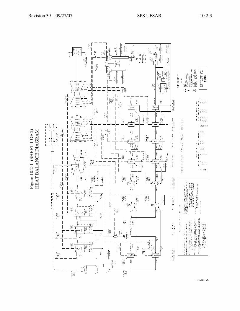
The design bases of the steam and power conversion equipment and systems are largelyderived from past design experience with fossil-fueled stations, and have evolved over a longperiod of time. Specifically, the design bases are oriented to a high degree of operationalreliability at optimal thermal performance. The performance of the collective equipment andsystems is a function of environmental conditions and the selection of design options. Therefore,the principal design basis is represented by the design heat balances, which incorporate all of theapplicable design considerations.
Figure 10.2-1 and Reference Drawing 1 shows the heat balance for the extended ratingequivalent to 2558 MWt.
The conventional design bases have been modified in order to provide suitability for nuclearapplication, and these include provisions for specific earthquake, tornado, and missile protectionas further described in other sections.
Turbine building Reference Drawings 2 through 9 show equipment locations.
A steam generator repair program was completed at the Surry Power Station in 1980 and1981 for Units 2 and 1, respectively. The purpose of the program was to repair degradation causedby corrosion-related phenomena and to restore the integrity of the steam generators to a levelequivalent to new equipment. The repair program basically consisted of replacing the steamgenerator lower assembly and refurbishing the upper assembly. New primary moisture separationequipment was installed in the upper assembly. The steam generators are described inSection 4.2.2.3 (primary-side characteristics) and Section 10.3.1.2 (secondary-sidecharacteristics).

Revision 39—09/27/07 SPS UFSAR 10.2-2
10.2 REFERENCE DRAWINGS
The list of Station Drawings below is provided for information only. The referenced drawings are not part of the UFSAR. This is not intended to be a complete listing of all Station Drawings referenced from this section of the UFSAR. The contents of Station Drawings are controlled by station procedure.
Drawing Number Description
1. 11448-FM-59M Heat Balance Diagram: 100% Core Power, Unit 1
11548-FM-59A Heat Balance Diagram: 100% Core Power, Unit 2
2. 11448-FM-6A Machine Location: Turbine Area, Plan, Operating Level, Unit 1
11548-FM-6A Machine Location: Turbine Area, Plan, Operating Level, Unit 2
3. 11448-FM-6B Machine Location: Turbine Area, Plan, Mezzanine Level, Unit 1
11548-FM-6B Machine Location: Turbine Area, Plan, Mezzanine Level, Unit 2
4. 11448-FM-6C Machine Location: Turbine Area, Plan, Ground Floor, Unit 1
11548-FM-6C Machine Location: Turbine Area, Plan, Ground Floor, Unit 2
5. 11448-FM-6D Machine Location: Turbine Area, Sections, Sheet 1, Unit 1
11548-FM-6D Machine Location: Turbine Area, Sections, Sheet 1, Unit 2
6. 11448-FM-6E Machine Location: Turbine Area, Sections, Sheet 2, Unit 1
11548-FM-6E Machine Location: Turbine Area, Sections, Sheet 2, Unit 2
7. 11448-FM-6F Machine Location: Turbine Area, Sections, Sheet 3, Unit 1
11548-FM-6F Machine Location: Turbine Area, Sections, Sheet 3, Unit 2
8. 11448-FM-6G Machine Location: Turbine Area, Sections, Sheet 4, Unit 1
11548-FM-6G Machine Location: Turbine Area, Sections, Sheet 4, Unit 2
9. 11448-FM-6H Machine Location: Turbine Area, Sections, Sheet 5, Unit 1
11548-FM-6H Machine Location: Turbine Area, Sections, Sheet 5, Unit 2
Revision 39—09/27/07 SPS UFSAR 10.2-3
Figu
re 1
0.2-
1 (
SHE
ET
1 O
F 2)
HE
AT
BA
LA
NC
E D
IAG
RA
M
Etia
m v
enen
atis
acc
umsa
n en
im. M
auris
rut
rum
, dia
m q
uis
tinci
dunt
ele
men
tum
, sem
orc
i bib
endu
m li
bero
, ut e
lem
entu
m
just
o m
agna
at a
ugue
. Aliq
uam
sap
ien
mas
sa, f
auci
bus
ac, e
lem
entu
m n
on, l
aore
et n
ec, f
elis
. Ves
tibul
um a
ccum
san
sagi
ttis
ipsu
m. I
n ul
lam
corp
er, d
ui s
ed c
ursu
s eu
ism
od, a
nte
wis
i dap
ibus
ligu
la, i
d rh
oncu
s ip
sum
mi a
t tel
lus.
Cla
ss a
pten
t ta
citi
soci
osqu
ad
litor
a to
rque
nt p
er c
onub
ia n
ostr
a, p
er in
cept
os h
ymen
aeos
. Qui
sque
rho
ncus
wis
i vita
e do
lor.
Etia
m
elei
fend
. Int
eger
impe
rdie
t veh
icul
a an
te. S
ed in
arc
u et
odi
o ac
cum
san
port
a. A
enea
n m
i. V
ivam
us n
on o
rci v
itae
urna
al
ique
t ulla
mco
rper
. Cla
ss a
pten
t tac
iti s
ocio
squ
ad li
tora
torq
uent
per
con
ubia
nos
tra,
per
ince
ptos
hym
enae
os. I
n fr
ingi
lla
ligul
a ve
l odi
o. In
hac
hab
itass
e pl
atea
dic
tum
st. E
tiam
tem
pus
lacu
s ac
arc
u. P
raes
ent n
on li
bero
.

Revision 39—09/27/07 SPS UFSAR 10.2-4
Figu
re 1
0.2-
1 (
SHE
ET
2 O
F 2)
HE
AT
BA
LA
NC
E D
IAG
RA
M
Etia
m v
enen
atis
acc
umsa
n en
im. M
auris
rut
rum
, dia
m q
uis
tinci
dunt
ele
men
tum
, sem
orc
i bib
endu
m li
bero
, ut e
lem
entu
m
just
o m
agna
at a
ugue
. Aliq
uam
sap
ien
mas
sa, f
auci
bus
ac, e
lem
entu
m n
on, l
aore
et n
ec, f
elis
. Ves
tibul
um a
ccum
san
sagi
ttis
ipsu
m. I
n ul
lam
corp
er, d
ui s
ed c
ursu
s eu
ism
od, a
nte
wis
i dap
ibus
ligu
la, i
d rh
oncu
s ip
sum
mi a
t tel
lus.
Cla
ss a
pten
t ta
citi
soci
osqu
ad
litor
a to
rque
nt p
er c
onub
ia n
ostr
a, p
er in
cept
os h
ymen
aeos
. Qui
sque
rho
ncus
wis
i vita
e do
lor.
Etia
m
elei
fend
. Int
eger
impe
rdie
t veh
icul
a an
te. S
ed in
arc
u et
odi
o ac
cum
san
port
a. A
enea
n m
i. V
ivam
us n
on o
rci v
itae
urna
al
ique
t ulla
mco
rper
. Cla
ss a
pten
t tac
iti s
ocio
squ
ad li
tora
torq
uent
per
con
ubia
nos
tra,
per
ince
ptos
hym
enae
os. I
n fr
ingi
lla
ligul
a ve
l odi
o. In
hac
hab
itass
e pl
atea
dic
tum
st. E
tiam
tem
pus
lacu
s ac
arc
u. P
raes
ent n
on li
bero
.
Revision 39—09/27/07 SPS UFSAR 10.3-1
10.3 SYSTEM DESIGN AND OPERATION
10.3.1 Main Steam System
The main steam system is shown on Figure 10.3-1 and Reference Drawing 1. The turbinegenerator heat balance for the 100% core power rating of 2546-MWt is shown on Figure 10.2-1and Reference Drawing 10. A review of the effects of the power uprate to a core power of2546 MWt was conducted and the main steam system was found to be adequate.
10.3.1.1 Design Basis
Each of the three main steam pipes is designed in accordance with the ASME Code forPressure Piping, ANSI B31.1, for a flow of 3,722,641 lb/hr of steam at 1085 psig, 555°F. Thepipes are each 30-inch o.d. ASTM A-155, Class 1, Gr. CMS-75 carbon steel, 1-inch nominal wallthickness, and join to form a common 36-inch o.d. header. Additional discussion of main steampiping materials may be found in Section 14B.5.1.6.3. Steam flows from this header through four28-inch o.d. pipes to the stop trip valves and the turbine.
The steam dump system is sized to take the excess steam flow associated with a 50% loadrejection, which results in a 10% step change in reactor power and a 40% steam dump, having asteam flow of approximately 4,504,000 lb/hr. This flow can be divided equally through the eightbypass control valves, with each valve having a maximum capacity of 890,000 lb/hr at full loadsteam conditions.
The 4200-rpm turbine-driven auxiliary feedwater pump is designed to deliver 700 gpm ofauxiliary feedwater to the steam generators at main steam pressures from 600 psig to 1100 psig.The turbine-driven auxiliary feedwater pump will also operate at main steam pressures from600 psig down to less than 120 psig and deliver the required auxiliary feedwater flow to the steamgenerators to support RCS decay heat removal prior to placing the residual heat removal system inservice. A main steam pressure of 120 psig corresponds to the approximate RCS conditions atwhich the residual heat removal system can be placed in service to remove decay heat. Steamtraps drain condensate from upstream of the inlet control valves to prevent water slugs fromentering the turbine. Removal of this condensate minimizes the risk of water slugs entering theturbine, flashing, and causing a pump trip on turbine overspeed.
The main steam piping supports were initially analyzed for turbine trip forces as well as forseismic forces. Since the turbine trip results in a more severe shock to the piping system than thedesign-basis earthquake, as set forth in Section 2.5, the turbine trip data were used in the design ofthe piping supports. In addition, the system was stress-analyzed for the forces and moments thatresult from thermal growth. The main steam piping within the containment annulus was reviewedfor possible pipe rupture, and sufficient supports and guides were provided to prevent damage tothe containment liner and adjacent piping. Stresses in the main steam piping inside containmenthave been reviewed and, in accordance with NRC Generic Letter 87-11, are sufficiently low thatonly terminal end breaks need be postulated.

Revision 39—09/27/07 SPS UFSAR 10.3-2
As a result of IE Bulletin 79-14 (Reference 1), the main steam piping and supports werereanalyzed in accordance with updated regulatory requirements. Minor support modificationswere made to satisfy analytical load limits. Pipe stresses were within allowable limits, so nopiping modifications were necessary. The reanalysis of safety-related piping systems and supportsis discussed in Appendix 15A.
10.3.1.2 Description
Each loop of the reactor coolant system contains a vertically mounted U-tube steamgenerator. The secondary-side characteristics of the steam generators are described below. Theprimary-side characteristics are described in Chapter 4. Steam generator design data are given inTable 4.1-4.
The steam generators, as shown on Figures 10.3-2 and 10.3-3, consist of two integralsections: an evaporator section and a steam drum section. The evaporator section consists of aU-tube heat exchanger, while the steam drum section houses moisture-separating equipment. Thesteam drum section is located in the upper part of the steam generator. In general, the steamgenerators are designed and manufactured in accordance with Sections II, III, and IX of theASME Boiler and Pressure Vessel Code. The lower assemblies are designed and manufactured inaccordance with the 1974 Edition of the ASME Code, including Addenda through Winter 1976.All components are designed to meet Section XI, Rules For Inservice Inspection of NuclearPower Plant Components. The steam generator lower assemblies bear the applicable ASME Codestamp.
Feedwater enters the unit through the nozzle located on the upper shell and is distributed bya feedwater ring into the downcomer annulus formed by the tube wrapper and steam generatorshell. The feedwater mixes with recirculation flow and enters the tube bundle near the tubesheet.Feedwater flow within the steam generators is divided so that a larger percentage of the flow isdirected to the hot-leg side of the tube bundle. This reduces the steam quality in the hot-leg side ofthe bundle and raises the steam quality in the cold-leg side. The effect of these changes in steamquality is to shift the point of highest steam quality at the tubesheet elevation toward the center ofthe bundle. Boiling occurs as the flow rises in the tube bundle.
The circulation ratio, which is defined as the total tube bundle flow divided by the feedwaterflow and is directly proportional to the steam quality exiting the tube bundle, is approximately 3.8.As circulation ratio increases, certain parameters of the steam generator, such as lateral velocity,steam quality, void fraction, and number of tubes exposed to sludge, change in a favorabledirection. Low steam quality in the bundle reduces tube exposure to local steam blanketing. Thisalso reduces the number of potential areas of concentration for chemical impurities. In addition,higher circulation ratios increase the flow exiting the downcomer and sweeping across thetubesheet to the center of the bundle. The point of highest steam quality and thus the lowestdensity is the center of the tube bundle, though, and is thus more susceptible to chemical

Revision 39—09/27/07 SPS UFSAR 10.3-3
concentration and sludge deposition. It is for this reason that the blowdown intake is located inthis region.
A set of sixteen 20-inch-diameter centrifugal moisture-separators, located 13 inches abovethe tube bundle, removes most of the entrained water from the steam. Steam dryers are employedto increase the steam quality to a minimum of 99.75% (0.25% moisture). The steam drum has twobolted and gasketed access openings for inspection and maintenance of the dryers, which can bedisassembled and removed through the opening.
The lower assemblies are constructed with four additional 6-inch access ports and two2-inch access ports in the area of the tubesheet. Four 6-inch access ports are located slightly abovethe tubesheet 90 degrees apart, with two located on the tube lane. Two additional 6-inch accessports are located on the tube lane, between the flow distribution baffle and the first support plate.At this same elevation, 90 degrees away, are two 2-inch access ports. The addition of these accessports improves and promotes inspection of the tubesheet and flow distribution baffle and assists inthe sludge-lancing procedure. The steam generator wrapper is designed to discourage flow in thetube lane yet allow clear access from the access ports.
Feedwater exiting from behind the wrapper in the vicinity of the tube lane will tend topreferentially channel to this path of less resistance and bypass part of the tube array. In order toprevent this flow channeling, a series of plates are placed in the tube lane. These plates block theflow into the tube lane and prevent channeling. These plates are arrayed so that there will be nointerference with the sludge-lancing procedure.
A flow distribution baffle is located approximately 18 inches above the tubesheet. Thisbaffle has a cutout center section and quatrefoil tube holes. The increased circulation ratioprovides a greater lateral flow across the tubesheet surface. The baffle plate will assist inredirecting the flow across the tubesheet, then up the center of the bundle through the centercutout. The design is sized to minimize the number of tubes exposed to sludge. Consistent withthis purpose, the design causes the sludge to deposit in and near the center of the bundle at theblowdown intake. The flow distribution baffle plate material is SA-240 type 405 ferritic stainlesssteel.
The tube support plates are SA-240 type 405 ferritic stainless steel. This material is ASMECode approved and is resistant to corrosion with the chemistry expected during the operation ofthe steam generator. In addition, SA-240 has a low wear coefficient when paired with Inconel andhas a coefficient of thermal expansion similar to carbon steel. Corrosion of SA-240 results in anoxide which has approximately the same volume as the parent material, whereas corrosion ofcarbon steel results in oxides that have a greater volume than the parent material. Type 405 alsohas material properties important to fabrication that are equivalent to carbon steel.
The quatrefoil tube support plate design, as shown on Figure 10.3-4, consists of four flowlobes and four support lands. The lands provide support to the tube during all operatingconditions, while preventing wear or fretting. This design has a lower pressure drop than the most

Revision 39—09/27/07 SPS UFSAR 10.3-4
current circulation hole designs. This low secondary pressure drop will cause a high circulationratio which, when combined with other improvements, translates into higher sweeping velocitiesand fewer tubes exposed to a low steam quality at the tubesheet. This design directs the flow alongthe tubes, which limits steam formation and chemical concentrations at the tube-to-tube supportplate intersections.
Each steam generator has two 2-inch, schedule 40 Inconel internal blowdown pipes. Theblowdown rate from the steam generator is varied as required by chemistry conditions in thefeedwater and as monitored in the blowdown. Maintenance of the steam-side water chemistry isassisted through the use of the blowdown system. Therefore, a continuous blowdown is preferredto intermittent blowdown. Continuous blowdown of the steam generator provides a dynamicsystem that is constantly removing impurities from the steam generator. During hot standby andhot functional testing, blowdown is employed as needed to maintain the steam generatorchemistry within specification. The blowdown intake location is coordinated with the baffle platedesign so that the intake is located where the greatest amount of sludge deposition is expected tooccur. The design of the steam generators allows the use of an efficient sludge removal system; atypical system is shown on Figure 10.3-5. A permanent sludge removal system is not installed. Areview of the effects of the power uprate to a core power of 2546 MWt was conducted and themain steam generator blowdown system was found to be adequate.
Steam-generator blowdown is discharged from the steam generators through two 2-inchschedule 40 Inconel internal blowdown pipes. The steam generators are designed to allowblowdown rates up to 7.4% of the feedwater flow rate; however, much of this is excess capacitybecause the blowdown system has a capacity of 1% of the feedwater flow rate.
A 3-inch line downstream of each steam generator blowdown containment isolation valvecarries the blowdown effluent from the auxiliary building into the turbine building through thepipe tunnel. Each blowdown line has a manual isolation valve, with a bypass valve provided forsystem start-up. Each blowdown line has a heat exchanger located adjacent to the east wall of therespective turbine building.
The system is designed for a maximum continuous blowdown from each steam generator of70 gpm at 750 psig and 510°F, and reduces the blowdown water to a maximum temperature andpressure of 130°F and 60 psig.
During power operation, after the blowdown is cooled, it is normally directed to thecondenser hotwell. The blowdown, along with condensate in the condenser, is filtered and treatedby condensate polishing prior to being returned to the steam generators. Alternately, steamgenerator blowdown may be released to the discharge canal through the condenser outletwaterbox. This activity is described in Section 10.3.5.2. Releasing to the discharge canal isnormally limited to unit start-up operation.
A pressure control valve (PCV) and a hand control valve (HCV) are provided downstreamof each heat exchanger assembly. The PCV will maintain a constant nominal pressure of 250 psig

Revision 39—09/27/07 SPS UFSAR 10.3-5
upstream of the HCV. If pressure upstream of the PCV decreases below 250 psig, the valve willtravel to the full-open position. The PCV will fail closed on a loss of control air, blowdown flowgreater than 75 gpm, or heat exchanger assembly outlet temperature greater than 145°F. The HCVis provided for remote/manual control of the steam generator blowdown rate. A remote controlstation is provided in the control room to position the HCV. The HCV is sized for a maximumblowdown rate of 70 gpm with an upstream pressure of 250 psig and a downstream pressure of50 psig. A pressure relief valve, set for approximately 200 psig, is provided to protect the systemdownstream of the HCV from overpressurization. A manually operated bypass valve is providedaround both the PCV and the HCV to allow manual control of the blowdown flow. Two flowelements are provided between the heat exchanger assembly and the PCV for high-range andlow-range flow indication.
Main condensate is used as the cooling medium for the heat exchangers. Approximately1260 gpm per unit (three heat exchangers) is supplied through an 8-inch supply header andisolation valve. The supply connection from the condensate system is located on the 24-inchcondensate header between the gland exhaust condenser and the flash evaporator. The return lineties into the condensate system at the cross-connect line between the fourth and fifth pointfeedwater heaters. Manual isolation valves are provided on each heat exchanger assembly. Theoutlet isolation valve is a globe valve to permit throttling of the cooling water flow. Thermometersare installed in the cooling water lines at the outlet of the heat exchanger assemblies to monitorcondensate return temperature. A relief valve is provided for each heat exchanger assemblybetween the isolation valves. The differential pressure across the drain coolers, fifth, and sixthpoint heaters will provide sufficient head for condensate flow through the steam generatorblowdown (SGBD) heat exchangers. To increase the condensate cooling capacity of the SGBDheat exchangers during low main condensate flow conditions, an independent SGBD heatexchanger condensate return divert line is added. The diverted heat exchanger condensate returnflow is controlled by a temperature controlled valve (TCV) which allows the diverted flow to bedischarged to the main condenser when the heat exchangers’ blowdown exit temperature reaches135°F.
Codes and standards applied to the steam generator blowdown system are listed inTable 10.3-1. The piping from the 3-inch connection downstream of the steam generatorblowdown containment isolation valves to the heat exchanger assemblies is classified ashigh-energy piping. This portion of the steam generator blowdown system is not safety relatedand has no seismic or tornado design requirements, except that its failure must not cause afunctional loss of any safety-related equipment. Postulated breaks have been analyzed, andrestraints added to prevent pipe whip or jet impingement damage to systems in the auxiliarybuilding that are required for safe shutdown.
A blowdown sampling system is provided in the Unit 1 turbine building. The system is usedto analyze a cooled blowdown sample before the blowdown stream is discharged to the dischargecanal through the condenser waterbox outlet.
Revision 39—09/27/07 SPS UFSAR 10.3-6
A 2-inch nozzle in the upper shell facilitates the wet layup of the steam generators duringthe periods of inactivity. The wet layup nozzle can be used for addition of chemicals during theseperiods to prevent any excursions of the water quality in the steam generator. The nozzle can alsobe used in conjunction with other systems to circulate water through the steam generator duringperiods of layup to prevent localized chemical concentrations. These same connections can alsobe used for chemical cleaning.
A steam generator recirculation and transfer system is provided to protect the steamgenerator internals from corrosive attack during inactive periods by enabling the water chemistryto be controlled during such periods. The system is used in conjunction with the steam generatornitrogen system described below to ensure the exclusion of oxygen from the steam generatorinternals during wet layup conditions. Each steam generator has an independent externalrecirculation loop with 150-gpm pumping capacity, which provides a complete volume turnoverapproximately every 4 hours. The recirculation and transfer system pump takes suction from thesteam generator upper shell. The pump discharges to the steam generator through the blowdownpipe via a connection to the steam generator blowdown system. Each circulation loop has a crossconnect to facilitate the transfer of a steam generator’s contents to either of the other two steamgenerators, the liquid waste system, or the circulating water discharge. During normal plantoperation, the system will be isolated from the steam generator by double isolation valves. Atypical wet-layup system is shown in Figure 10.3-6.
The steam generator nitrogen system is utilized in conjunction with the steam generatorrecirculation and transfer system to protect the steam generators during long layup periods fromcorrosive attack by ensuring the exclusion of oxygen from the secondary side of the steamgenerators. The system includes a vacuum pump to enable the air to be evacuated from the steamgenerator before nitrogen is introduced from a nitrogen supply. However, the vacuum pump is nolonger used. Connection to the secondary side of the steam generator is made by a 2-inch lineconnected to the 6-inch main steam trip valve bypass line in the main steam valve house. Anisolation valve is provided to isolate this system from the steam system during unit operation. Thissystem is a quality group B system from the bypass line up to and including the isolation valve,with the rest of the system being quality group E.
A loose parts monitoring system has been installed and provides the ability to monitor theprimary system and secondary side of the steam generators for the presence of loose circulatingparts and other foreign objects. See Section 4.2.10 for further information.
All pressure-containing parts, with the exception of the Inconel tubes, are made of carbon orlow-alloy steel. The stainless steel insulation of the steam generator is designed to facilitateremoval for maintenance and inservice inspection activities.
Steam is conducted from each of the three steam generators through a steam flowmeter(venturi), a swing disk-type valve and an angle-type nonreturn valve into a common header

Revision 39—09/27/07 SPS UFSAR 10.3-7
outside the containment. The steam passes from the header to the turbine stop-trip valves and thento the governor valves. The steam flowmeter sends a signal to the feedwater control system.
The swing disk-type trip valves in series with the nonreturn valves contain swinging disksthat are normally held up and out of the main steam flow path by air cylinder operators.Three-way solenoid-operated air control valves function to hold the trip valves open when airpressure is applied. The valves are designed to close on release of air pressure, but are notdependent on air pressure to assist closure. When the air pressure is vented, the valve discs shutrapidly due to spring pressure and the steam flow differential pressure. The air cylinders areequipped with rupture discs to prevent damage to valve and actuator parts from being overstresseddue to the rapid cylinder pressure increase when the valves shut at high steam flow rates. Air isnormally available at 100 psig, but the equipment is designed to operate at a minimum airpressure of 70 psig. Electrical power to the solenoid-operated air control valves is available at125V dc.
The main steam-line trip valve circuitry has been modified to ensure that the trip valves willnot return to their non-safety position (open) following the resetting of the consequence limitingsafeguards (CLS) system signal when power to train A or B is lost. The modification required theinstallation of an additional contact deck to each trip valve selector switch located at thebenchboard in the control room and the installation of a new limit switch to each trip valve. Thismodification provides a seal-in function in the train B control circuitry similar to that existing inthe train A portion of the circuit. As a result, when resetting a CLS signal, if power is lost in eithertrain A or B, the valve will not return to its non-safety position. All electrical equipment installeddue to the above modification that could experience a harsh environment is qualified toIEEE 323-1974, IEEE 344-1975, and IEEE 383-1974.
The trip valves close following receipt of an excess flow signal from the steam flowmeter tothe solenoid-operated air control valves. The electrical signal positions the air control valves torelease air pressure on the air cylinder operators, and spring action causes the trip valve disks tomove into the steam path and trip closed. The operating mechanisms are designed and constructedto withstand the pressures and temperatures that result from dashpot action after the valve disk hasmoved into the steam path. Rapid closure of the trip valves prevents flashing of the water on theshell side of the steam generators, which in turn prevents a rapid decrease in reactor coolanttemperature on the tube side of the steam generators.
In addition to the three-way solenoid-operated air control valves described in this section,two solenoid-operated valves have been added to each main steam line trip valve to provide analternate means of closure at either the control room (in the event of a fire in the emergencyswitchgear room) or at the emergency switchgear room (in the event of a fire in the control room).The cables, solenoid valves, control switches, and battery/battery chargers required to power thetwo additional SOV’s are qualified to meet or exceed the normal environmental conditions for theareas where they will be installed. The cables that supply the two SOVs are environmentally

Revision 39—09/27/07 SPS UFSAR 10.3-8
qualified in accordance with IEEE 323-1974. See Section 9.10.4.1 for information on 10 CFR 50Appendix R requirements in relation to this modification.
The air operators are also used to open the trip valves. With 70 psig applied to bothoperators, the trip valves will open with a maximum differential pressure of 4 psi across the valveseat. Manually operated bypass valves permit pressure to be balanced across the valve beforereopening.
The motor-operated nonreturn (stop-check) valves automatically prevent reverse flow ofsteam in the case of accidental pressure reduction in any steam generator or its piping, and alsoprovide a shut-off of steam from its respective steam generator.
A total of five ASME Code safety valves are located on each main steam line outside thereactor containment and upstream of the trip valves. Four 6-inch by 10-inch valves and one 4-inchby 6-inch valve are provided, for a total relieving capacity of 3,842,454 lb/hr.
Excess steam generated by the residual and sensible heat in the core and the reactor coolantsystem is normally bypassed directly to the condensers by means of two 14-inch steam dumplines, which provide a total bypass capacity of 40% of normal full-load steam flow. Each steamdump line contains a bank of four steam dump control valves arranged in parallel. These valvesare controlled by reactor coolant average temperature with provisions to control a portion of thevalves with steam pressure. An uncontrolled unit cooldown caused by a single valve sticking openis minimized by the use of a group of valves installed in parallel.
All or several of the steam dump valves open under the following conditions, provided acondenser vacuum permissive interlock is satisfied:
1. On a large step load decrease, the steam dump system creates an artificial load on the steamgenerators, thus enabling the nuclear steam supply system to accept a 50% load rejectionfrom the maximum capability power level without reactor trip. An error signal exceeding aset value of reactor coolant Tavg minus Tref will fully open all valves in 5 seconds. Tref is afunction of load and is set automatically. The temperature-controlled valves closeautomatically as reactor coolant conditions approach their programmed set-point for the newload.
2. On a turbine trip with a reactor trip, the pressure in the steam generators rises. To preventoverpressure without main steam safety valve operation, the steam dump valves open anddischarge to the condenser for several minutes, to provide time for the reactor control system(Section 7.3) to reduce the thermal output of the reactor without exceeding acceptable coreand coolant conditions.
3. After a normal orderly shutdown of the turbine generator leading to unit cooldown, the steamdump valves are used to release steam generated from the residual and sensible heat forseveral hours. Unit cooldown is controlled to minimize thermal transients and is based on

Revision 39—09/27/07 SPS UFSAR 10.3-9
residual and sensible heat release. It is effected by manual control of the steam dump valvesuntil the cooldown process is transferred to the residual heat removal system (Section 9.3).
4. During start-up, hot standby service, or physics testing, the steam dump valves are operatedfrom the control room. The Steam Header Pressure Controller can be used in the Automaticor Manual control mode while maintaining the plant at no load conditions or during start-upwith power less than approximately 15%.
All steam dump valves are prevented from opening on loss of condenser vacuum, andexcess steam pressure is relieved to the atmosphere through the steam generator power operatedrelief valves or the main steam safety valves. Interlocks are provided to reduce the probability ofspurious opening of the steam dump valves.
An interlock is also provided to close all steam dump valves by venting the valve actuatorswhenever the reactor coolant system temperature in two out of three loops falls below 543°F(nominal). This interlock is redundant down to two solenoids per steam dump valve, which ventthe valve actuator. This interlock ensures that any failure in the steam dump control systemoccurring in the normal operating temperature range above 543°F (nominal) can cause acooldown only to 543°F (nominal) at which point all valve actuators are vented and, thus, allvalves are closed.
A steam generator power operated relief valve with an adjustable setpoint is provided oneach main steam safety valve header, upstream of the trip valve outside the containment. Therelieving pressure of these valves, normally 1035 psig, is individually controlled from the controlroom, and each valve has a capacity of 373,000 lb/hr. A key lock selector switch EMERGCLOSE—NORMAL has been added to the existing analog circuit of the associated controls foreach of the three power operated atmospheric relief valves. This provides the operator with theability to close the relief valves by interrupting the analog signal, which normally controls theposition of the relief valves. These selector switches are located in the cable vault and tunnelwhere the operator can operate the relief valves in the event of a fire in the control room or theemergency switchgear room. These valves which are equipped with quick-connect instrument airfittings can be operated locally with a portable air source if required. The steam generator poweroperated relief valves are equipped with a backup bottled air system so that they can be operatedfrom within the containment spray pump house in the event of loss of offsite power.
Steam leaving the high pressure turbine passes through four moisture separator-reheaterunits in parallel to the inlets of the low pressure turbine cylinders. Each of the four steam linesbetween the reheater outlet and LP turbine inlet is provided with a crossover stop valve and anintercept valve in series. These valves, operated by the turbine control system, function to controlturbine overspeed. Six ASME code safety valves are installed on each crossunder line between thehigh pressure turbine exhaust and the moisture separator inlet to protect the separators andcrossunder system from overpressure. The valves are sized to pass the flow resulting from closure
Revision 39—09/27/07 SPS UFSAR 10.3-10
of the crossover stop and intercept valves with the main steam inlet valves wide open. Althoughthis event is unlikely, the valves discharging to atmosphere prevent equipment damage.
Steam is supplied to the turbine drive for the auxiliary feedwater pump from each steam lineupstream of the main steam trip valves. The steam lines to the turbine are continuously understeam generator pressure up to the shut-off valves located at the turbine drive. The air-operatedsteam supply valves for the auxiliary feedwater pump are operable from the control room or theauxiliary shutdown panel. Operation of these valves is also initiated automatically from a loss ofpower signal or on a low-low level signal in two of three steam generators. Indication of operatingconditions is provided in the control room to enable the operator to adjust feedwater flow with anyof the six motor operated valves shown on Reference Drawing 6.
Temperature flow probes are installed on the discharge side of the 15 main steam safetyvalves to monitor safety relief valve position on the main steam system. Valve position isindirectly “measured” by comparing discharge temperatures with respect to ambient temperatureswith the valve closed. This indirectly determined valve status is transmitted through the ERFDAS(Emergency Response Facility Data Acquisition System) which provides the control roomoperator with a CRT display on the open or closed valve status for each of the main steam safetyrelief valves.
10.3.1.3 Performance Analysis
The steam generator repairs effected in 1979 and 1981 incorporated design features toeliminate various forms of tube degradation. The design features combined with inserviceinspections will help ensure that tube integrity is maintained. The acceptability of the repairedsteam generators is discussed in detail in a safety evaluation by the Office of Nuclear ReactorRegulation dated December 15, 1978 (Reference 2).
Design criteria for the steam generator lower assemblies require that tube vibration, tubefatigue, and tube support plate hole enlargement be within acceptable limits. As a result,flow-induced tube vibration caused by turbulence, fluid elastic excitation, and vortex sheddinghas been evaluated. The evaluation shows that the maximum alternating bending stress in a tube is1.2 ksi. The code allowable number of cycles at this stress level is infinite and the fatigue usagefactor is zero. Furthermore, the wear coefficient of SA-240 type 405 stainless steel, when pairedwith Inconel tubing at normal operating temperatures, is lower than that for carbon steel;therefore, initial tube clearances will be maintained and tube support conditions will not changenoticeably during the lifetime of the steam generator.
If a main steam pipe rupture occurs, a flow signal measured by the venturi flowmeterlocated in that main steam line causes the swing check trip valves in all three main steam lines totrip closed. The trip valves are assumed to close within 10 seconds from the time the processvariable reaches the trip setpoint. This time is comprised of three components: one second for theinstrument response time delay from the time the setpoint is reached until bleed off of instrumentair pressure is initiated, a maximum of 4 seconds to bleed off the instrument air pressure from the

Revision 39—09/27/07 SPS UFSAR 10.3-11
main steam trip valve operating cylinders, and a maximum of 5 seconds as closure time for thevalve. If the rupture occurs downstream of the trip valves, valve closure stops the flow of steamthrough the pipe rupture, thus checking the sudden and large release of energy in the form of mainsteam. This prevents rapid cooling of the reactor coolant system and an ensuing positive reactivityinsertion. Trip valve closure also ensures a supply of steam to the turbine drive for thesteam-driven auxiliary feedwater pump described in Section 10.3.5.
If a steam line breaks between a trip valve and a steam generator, the affected steamgenerator continues to blow down. The nonreturn valve in the ruptured line prevents blowdownfrom the other steam generators. Steam-break accidents are discussed in Section 14.3.2.
10.3.1.4 Secondary Plant All-Volatile Chemistry Treatment
Phosphate chemistry was used prior to 1975, but both units changed to all-volatile treatment(AVT) in January 1975. A chemistry monitoring program has been implemented to inhibit steamgenerator tube degradation. Discussion of the monitoring system is provided in Section 9.6,Sampling System.
Condenser inleakage, contaminants from condensate polishing, and condensate/feedwatersystem corrosion products are the major sources of chemical agents that have the potential foraccumulating as sludge on the steam generator tubesheet, producing deposits on steam generatorheat transfer surfaces. The feedwater is the means by which these chemical agents are transportedto the steam generator. AVT chemistry provides no buffer against the effects of condenserinleakage; it is incapable of preventing the formation of scale should the chemical agents that havethe propensity for scale formation be present, and the ammonium hydroxide or the amines addedto the system for feedwater pH control have minimum effectiveness as steam generator pH controlagents at the operating temperature in the steam generator. Therefore, to accomplish the goal ofmaintaining the secondary system in an all-volatile chemistry environment that is innocuous tothe steam generator materials, it is necessary to minimize the introduction of contaminants andcorrosion products to the system. In addition to providing the proper environment for the steamgenerator, a well-maintained AVT chemistry program will accomplish the following:
1. Maintain the integrity of system components.
2. Minimize turbine deposits due to carryover from the steam generators.
3. Minimize sludge in the steam generators.
4. Minimize scale deposits on the steam generator heat transfer surfaces.
5. Minimize feedwater oxygen content prior to entry into the steam generators.
6. Minimize corrosion of the condensate/feedwater system materials.
7. Maintain chemistry near neutral in steam generator crevices.
8. Maintain desired dissolved oxygen level.

Revision 39—09/27/07 SPS UFSAR 10.3-12
These objectives can be achieved by exercising chemistry control over the systems,including sampling and analysis, chemical injection at selected points, continuous systemblowdown from the steam generator, and effective protection of the steam generator andfeedwater train internals during periods of inactivity. The objectives are accomplished by meetingsteam generator control parameters specified by the Nuclear Plant Chemistry Program. Thespecifications are based on the EPRI, PWR Secondary Water Chemistry Guidelines, including:
1. The use of approved amine(s) for feed water and steam pH control (ammonium hydroxide,morpholine, ethanolamine, and cyclohexylamine are acceptable).
2. The use of an approved oxygen scavenger in the feedwater train.
3. Continuous blowdown and continuous chemical addition.
4. Limiting the concentrations of contaminants in the feedwater and in the steam generator.
For corrosion prevention, the ingress of oxygen into the steam generators should beminimized. Oxygen should be less than 0.005 ppm in the blowdown under any operating or testcondition. Oxygen is controlled by the addition of an oxygen scavenger. During hot standby, theconcentration of oxygen in the feedwater can be 0.1 ppm or less, provided the concentration ofoxygen scavenger injection into the steam generator is within recommended limits.
The concentration of oxygen scavenger in the steam generators during hydro and wet layupmust be adequate to minimize dissolved oxygen and passivate the covered metal surfaces.
When controlling steam generator chemistry on AVT chemistry, it must be recognized that(1) AVT provides no buffering capacity for contaminants entering the steam generator, and (2) thesteam generator bulk water pH is at or slightly in excess of the neutral pH for water at theoperating temperature of the steam generator. The absence of alkalinity in the steam generator atits operating temperature is due to the low ionization of the feedwater pH control amines at thesetemperatures. Therefore, contaminants entering the steam generator that are more strongly ionizedthan the feedwater pH control amines have the potential for producing perturbations to the bulkwater either in the form of free hydroxide (from fresh waters) or acidity (sea water or treatedcirculating water). The objectives of the steam generator chemistry control parameters are toprovide a means for controlling the steam generator crevice chemistry to minimize corrosion ofthe steam generator and turbine cycle materials, and to provide a means whereby perturbations tothe steam generator chemistry from sources such as condenser inleakage can be recognized.
In the recirculating steam generator, the only bulk water losses from the steam generator arethe blowdown and the moisture that is entrained in the steam. Therefore, any contaminantentering the steam generator will tend to concentrate until corrective action is taken.
Based on the type of steam generator degradation that has been observed at pressurizedwater reactors (PWRs) cooled by seawater and brackish water, emphasis should also be placed onthe control of sodium. Inconel 600 steam generator tubing is susceptible to caustic inducedIGA/IGSCC, and because of this, every effort must be made to exclude free hydroxide from the

Revision 39—09/27/07 SPS UFSAR 10.3-13
steam generator environment. Operational control of the steam generator sodium to chloridemolar ratio is recommended to achieve near-neutral chemistry in the steam generator crevices.The controlled addition of chloride may be warranted to counter excess sodium ions.
Protection of the steam generators during inactive periods due to maintenance and refuelingrequires placing the steam generators in a layup condition. To ensure the long-term performanceof the steam system, the same degree of chemical control exercised during normal operationshould be exercised during shutdown conditions.
Periods of hot shutdown and hot standby operation require that steam be released from thesteam generators to release heat in the reactor coolant system due to heat input from reactor coredecay heat and reactor coolant pump heat. Chemistry control is applied during such operationssimilar to that exercised during normal operating conditions.
Secondary-water chemistry specifications should be adhered to during all phases of unitoperation. When specifications are exceeded, operator action is taken as recommended in thestation’s chemistry control program.
10.3.1.5 Tests and Inspections
The turbine overspeed protection is checked during normal unit start-up. The steam dumpsystem also functions during unit start-up. Operation of the steam generator power operated reliefvalves is checked at start-up and also periodically during normal operation.
The turbine-driven auxiliary feedwater pump is tested in accordance with the TechnicalSpecifications.
Safety-related main steam components are tested in accordance with TechnicalSpecifications.
During unit shutdown, the tripping mechanisms for the trip valves are tested for properoperation. The nonreturn valves are also tested to verify that they are functional.
10.3.2 Auxiliary Steam System
An auxiliary steam system is provided as shown in Figure 10.3-7 and Reference Drawings 2and 3. All piping is designed in accordance with the ASME Code for Pressure Piping,ANSI B31.1. A review of the effects of the power uprate to a core power of 2546 MWt wasconducted and the auxiliary steam system was found to be adequate.
10.3.2.1 Design Basis
Steam from the secondary system is reduced in pressure and supplied to the auxiliary steamsystem for space heating, process system heat exchangers, and process system air ejectors. Nearlyall secondary steam used in the auxiliary steam system is condensed, returned to the condensatesystem, and then sent to either the condensate storage tank or the main condenser. A small

Revision 39—09/27/07 SPS UFSAR 10.3-14
quantity of secondary steam used in the auxiliary steam system for the after condenser air ejectorsand containment vacuum ejectors is not returned to the condensate system for reuse. Auxiliarysteam used in the after-condenser air ejectors is condensed and drained to the storm sewagesystem or returned to the condenser. Auxiliary steam used in the containment vacuum ejectors isejected to the atmosphere through the roof of the auxiliary building.
The auxiliary steam system supplies 150 psig saturated steam throughout the station forauxiliary services.
Turbine building uses of auxiliary steam are as follows:
1. Main condenser air ejector.
2. Space heating.
3. Gland seal steam.
Auxiliary building uses of auxiliary steam are as follows:
1. Boron recovery system heat exchangers.
2. Chemical and volume control system (boric acid batch tank heating).
3. Containment vacuum ejectors.
4. Space heating.
Auxiliary steam is used in the yard for the following purposes:
1. Boron recovery tank heating.
2. Primary-grade water tank heating.
Auxiliary steam is used for space heating in the following additional areas:
1. Fuel building.
2. Decontamination building.
3. Safeguards area.
4. Service building area.
a. Shops.
b. Mechanical equipment rooms 1 and 2.
c. Emergency generator rooms.
d. Boiler room.
The service building, including locker rooms, laboratories, offices, instrument shop,mechanical room, assembly room, and first-aid room are heated by steam coils in air-handling and
Revision 39—09/27/07 SPS UFSAR 10.3-15
air-conditioning units that serve these areas. All of these air-handling units are installed in themechanical equipment rooms 1 and 2.
No auxiliary steam is used in the operations administration building. It is heated by hotwater and steam-heated ventilation air. The hot water converter and the air-conditioning unitcontaining the steam coil for ventilation heating are installed in the turbine building.
10.3.2.2 Description
Normally, the auxiliary steam supply header receives its steam requirements from thesecond point extraction lines. During periods of low load operation when second point extractionsteam pressure drops below approximately 140 psig, steam is supplied from the main steamheader through a pressure-reducing valve. When both reactors are shut down, steam is supplied bythe heating boilers.
The containment vacuum system steam ejectors are used only during start-up periods toinitially evacuate the containment. During normal operation, two mechanical vacuum pumpsmaintain the vacuum, as described in Section 5.3.4.
Two heating boilers, each rated at 80,000 lb/hr of steam, are provided for preliminary andshutdown operation. Each boiler is the packaged water tube type and is equipped withmotor-driven fuel-oil pumps, deaereator, and feedwater pumps. Number 2 fuel oil is supplied tothe boilers from the main oil storage tanks.
10.3.2.3 Performance Analysis
A loss of normal ac power will shut down the heating boilers. No services supplied byauxiliary steam are required to function as part of engineered safeguards during a loss of stationpower.
10.3.2.4 Tests and Inspections
Routine inspections are performed on a periodic basis.
10.3.3 Turbine Generator
The turbine-generator heat balance for the 100% core power rating of 2546 MWt is shownin Figure 10.2-1 and Reference Drawing 10.
10.3.3.1 Turbine
The turbine is a conventional 1800-rpm tandem compound unit consisting of onedouble-flow high-pressure cylinder and two double-flow low-pressure cylinders (BuildingBlock 81). The turbine disks are Ni-Cr-Mo-V steel. Periodic inservice inspections are conductedto verify the integrity of the internal components of the turbines. An analysis of turbine missilerisk is provided in Section 14.2.13. The inspections are conducted at a frequency consistent with

Revision 39—09/27/07 SPS UFSAR 10.3-16
the methodology specified in Reference 7. The inspection interval of the low pressure turbineblading is dictated by Technical Specifications.
The turbine is expected to achieve a maximum capability of 855,408 kW gross with inletsteam conditions of 748 psia and 0.25% moisture exhausting to 1.5 inch Hg (absolute) with afeedwater temperature of 441.1°F and 0.5% makeup. The turbine is provided with six stages offeedwater heating and four moisture-separator reheaters located between the high-pressure andlow-pressure cylinders.
Each high-pressure steam line to the high-pressure cylinder contains a stop-trip valve and agovernor control valve. Stop valves and intercept valves are provided at the discharge of themoisture-separator reheaters to the low-pressure turbine cylinders.
A gland steam sealing system is provided to prevent air inleakage and steam outleakagealong the turbine shaft. All necessary piping, controls, and a gland steam condenser are provided.
The turbine oil systems include a conventionally designed electro-hydraulic-controlledgoverning-trip system. There is also a low-pressure bearing lubrication system, discussed inSection 10.3.7.
Overspeed protection is provided through use of an overspeed trip mechanism that consistsof an eccentric weight mounted in a transverse hole in the turbine rotor extension shaft.Centrifugal force moves the weight outward against spring compression. When the turbineoverspeeds to a point at which the mechanism is set to operate, the spring compression isovercome by the centrifugal force of the rotor speed, and the weight moves out to strike a trigger,which trips the overspeed trip valve and releases the auto-stop oil and operating fluid to drain.
Additional turbine overspeed protection utilizes the output of magnetic pickups mountedadjacent to the turbine shaft. A toothed wheel on the shaft provides a fluctuation magneticcoupling for the speed transducer pickups. The speed transducer senses fluctuations and translatesthem into a sine wave whose frequency is proportional to turbine speed. This signal is fed to theauxiliary governor. If the control subsystem senses an overspeed condition (103% speed), and thegenerator is not in parallel with the grid or if electrical output is less than 5%, then the auxiliarygovernor provides a control signal to SOVs in the EHC subsystem which depressurizes thegovernor valve emergency trip header. This trips the governor and intercept valves closed whilethe overspeed signal is present in an attempt to limit the overspeed and prevent an overspeed trip.Once the turbine speed decreases below 103% of rated speed, the solenoids close and the interceptvalves start to reopen immediately followed by the governor valves after five seconds. When thegenerator is in parallel with the grid and electrical output is greater than 5% then the auxiliarygovernor’s overspeed function is disabled. This is because this protection is not needed whenthese conditions are met due to the fact that synchronous generators in parallel must operate atgrid frequency and physically can not overspeed.

Revision 39—09/27/07 SPS UFSAR 10.3-17
The Reverse Power protection system provides two forms of turbine protection. Excessiveheat damage to the turbine is prevented during generator motoring by tripping the generatorbreakers 40 seconds after sensing the reverse power condition. Additional turbine overspeedprotection is provided by using the reverse power relay to provide sequential tripping.
Sequential tripping is the inclusion of a reverse power relay in series with any trip circuitsusing steam valve close position switches. This will provide security against possible overspeedby ensuring that all sources of steam to the turbine are reduced below the amount required toproduce overspeed before the generator breakers and excitation breakers are tripped. In addition,the reverse power relay provides a time delayed backup trip in the case of failed or misadjustedvalve position switches.
This protection will not override the generator or switchyard protection that instantaneouslyopens the generator breaker when an electrical fault occurs that might cause serious and certaindamage to the generator or switchyard equipment.
10.3.3.2 Generator
The hydrogen inner-cooled generator rating is 1,055,000 kVA at 75 psig hydrogen gaspressure, 0.90 pf, three-phase, 60 Hz, 22 kV, and 1800 rpm. The Unit 1 generator has a0.540 SCR, while the Unit 2 generator has a 0.559 SCR. The Unit 1 generator will be operated at941,700 kVA at 60 psig hydrogen gas pressure and the Unit 2 generator will be operated at941,700 kVA at 75 psig hydrogen gas pressure as discussed in Section 8.2.
Primary protection of the main generator is provided by differential current and field failurerelays. Protective relays automatically trip the turbine stop valves and electrically isolate thegenerator.
A rotating rectifier (brushless) exciter with a response ratio of 0.5 is provided for both units.The exciter rating is 4700 kW, 570V dc, and 1800 rpm. The exciter consists of an ac alternatorcoupled directly to the generator rotor. The alternator field winding is stationary, and control ofthe exciter is applied to this winding. The alternator armature output is rectified by banks ofdiodes that rotate with the armature. This direct current output is carried through a hollow sectionof the shaft and is applied directly to the main generator field.
The 22-kV generator terminals are connected to the main step-up transformer and the unitstation service transformers by 22-kV aluminum conductors, each rated at 26,000A. Eachaluminum conductor is enclosed in a forced-air-cooled, isolated-phase bus duct. Furtherdiscussion of the interconnection between the generator and the transmission system is containedin Section 8.3.
Hydrogen seal-oil pumps are furnished to provide seal oil to the generator shaft seals for theprevention of hydrogen leakage from the generator. An ac motor-driven high-pressure hydrogenseal-oil back-up pump and a dc motor-driven, air side seal-oil backup pump are provided. A

Revision 39—09/27/07 SPS UFSAR 10.3-18
continuous bypass-type oil purification system removes water and other contaminants from theoil.
Since a mixture of hydrogen and air is explosive over a wide range of proportions (fromabout 4 to 70% hydrogen by volume), the design of the generator and the specified operatingprocedures are such that explosive mixtures are not possible under normal operating conditions.In order to provide for some unforeseen condition brought about by the failure to follow thecorrect operating procedure, it is necessary to design the frame to be explosion-safe. The intensityof an explosion of a mixture of air and hydrogen varies with the proportions of the two gasespresent. A curve on which the values of intensity are plotted against the proportions of gases willapproximate a sine wave, having zero values at 5 and 70% hydrogen and reaching a maximumintensity at a point half way between these limits. The term “explosion-safe” is intended to meanthat the frame will withstand an explosion of this most explosive proportion of hydrogen and air ata nominal gas pressure of 2 or 3 psig without damage to life or property external to the machine.This nominal pressure of 2 or 3 psig is that which might be obtained if hydrogen were accidentlyadmitted during the purging operation instead of carbon dioxide, as specified. Such an explosionmight, however, result in damage or dislocation of internal parts of the generator. When changingfrom one gas to another, the generator is vented to the atmosphere, so that a positive pressure ofmore than 2 or 3 psig will not be built up.
10.3.4 Circulating Water System
The circulating water system, Reference Drawing 4, provides cooling water for the maincondensers and the service water systems of both units. A review of the effects of the poweruprate to a core power of 2546 MWt was conducted and the circulating water system was found tobe adequate.
10.3.4.1 Design Basis
To prevent the direct recirculation of the heated circulating water discharge, the system isdesigned to take water from the James River on the east end of the site and to discharge to theJames River on the west end of the site. The shoreline distance between the intake and dischargepoints is about 5.7 miles, and the overland distance across the peninsula is about 1.9 miles.
Each unit requires 840,000 gpm of river water to supply condensing and service waterneeds. To provide operational flexibility, system reliability, and station economy, the waterrequirement for each unit is supplied by four 220,000-gpm pumps. These pumps discharge to thecommon high-level intake canal that conveys the circulating water to the station area. Coarse trashis removed from the circulating water by trash racks at the river intake structure, and finer trash isremoved at the river intake and at the entry-bay and station ends of the intake canal by two sets oftraveling water screens. The circulating water flows by gravity from the high-level intake canalthrough four buried parallel lines to each condenser and then through four separate lines to aconcrete tunnel for each unit. The tunnels terminate at seal pits located at the edge of thecirculating water discharge canal, which is common to both units.

Revision 39—09/27/07 SPS UFSAR 10.3-19
The discharge canal conveys the flow to the James River. The discharge channel within theriver is provided with rock groins along each side to control sedimentation and to maintain exitvelocities of the circulating water to achieve desired dilution effects of the heated effluent.
Some components of the circulating water system are used for handling service water, andare therefore designed as Seismic Category I structures and components. These components are:
1. The circulating water intake structure at the river.
2. High-level intake canal.
3. High-level intake structure.
4. Buried circulating water piping and valves between the high-level intake canal and thecirculating water discharge tunnel.
5. Circulating water discharge tunnel.
6. Seal pits.
7. Intake canal low-level isolation level switches (1-CW-LS-102 & 103, 2-CW-LS-202 & 203).
10.3.4.2 Description
The circulating water is withdrawn from the James River through a channel dredged in theriver bed. The original channel invert was 150 feet wide at Elevation -13.3 ft. It extended adistance of approximately 5000 feet to the main river channel. A natural river channel bisects thedredged channel approximately 2000 feet from the shore. This inner portion of the dredgedchannel is periodically monitored and dredged as necessary to support plant operations. Thecombination of the natural channel and the dredged channel is also used for shipping materialsand equipment to the permanent dock on the east side of the site.
The circulating water intake structure is located at the shore end of the river intake channeland is an eight-bay reinforced-concrete structure. The exposed deck of the structure is atElevation +12 ft. The invert of the intake structure is at -25.25 feet. Each bay houses one of theeight circulating water pumps for the two units. These pumps are rated 220,000 gpm at 28 feettotal dynamic head when running at 220 rpm. Each pump is driven by a vertical, solid-shaft,2000-hp, induction motor. The pumps are of the nonpullout type and are serviced using mobilehoisting equipment. Before entering the pumps, river water passes through a trash rack andtravelling screen at the mouth of each bay. The travelling screens are provided with deflector flapsand screenwash pumps for low-pressure water spray. The deflector flaps ensure that fish dumpedfrom the screens are deflected into a trough for transport via an effluent flume back to the JamesRiver. The low pressure spray ensures more efficient washing of fish from the screens into the fishcollector trough. The trash rack is serviced by a movable trash rack rake that discharges collectedtrash to a receptacle where it accumulates until trucked off-site for disposal. In the event of apower failure, accumulated trash can be removed by manual raking. This process could continue
Revision 39—09/27/07 SPS UFSAR 10.3-20
indefinitely; however, it is expected that any power failure at the station low-level intake would beof relatively short duration.
Each circulating water pump discharge line is a 96-inch diameter steel pipe that conveys thewater over the embankment of and into the high-level intake canal. At the crest of the canalembankment, the crown of the pipe is provided with a pair of active vacuum breakers (valves) anda tap for the vacuum priming system. The vacuum priming system prevents air accumulation inthe pump discharge line while the pump is operating. This system is isolated when the circulatingwater pumps are de-energized. The active vacuum breakers open when the circulating water pumpis de-energized. These vacuum breakers prevent loss of water from the high-level intake canal bysiphoning through idle pumps. A passive vacuum breaker, designed to conserve intake canal waterin the event of a failure of the paired active vacuum breaker valves, is located on the discharge endof each 96-inch diameter pipe. The passive vacuum breaker consists of a 20-inch diameter lowprofile vertical pipe protection which extends to Elevation +25 ft. of the intake canal. The passivevacuum breakers are designed to interrupt the postulated siphon action prior to reaching thetechnical specification limitation for canal water level.
The high-level intake canal is about 1.7 miles long and is designed to convey the circulatingwater flow to the station. The canal is paved with 4.5 inches of reinforced concrete, to allowvelocities that would otherwise erode the earthen materials through which the canal isconstructed. Since these earthen materials have low permeabilities, significant loss of waterthrough the canal lining and into the substrata is not considered probable. The bottom width alongmost of the length of the canal is 32 feet, and the canal has side slopes of 1.5 feet horizontal to1 foot vertical. The invert elevation varies from Elevation +5 ft. at the station end of the canal toElevation +6.8 ft. at the river end of the canal. The berm along each bank of the canal is atElevation +36 ft.
The water levels in the canal are controlled by the piping system friction losses within thepower station and the prevailing river level. The normal water elevation at the power station end ofthe canal will vary between Elevation +26 ft. and Elevation +30 ft., depending upon the tide. Aminimum freeboard greater than four feet is maintained between the canal water surface and theberm at Elevation +36 ft. during hurricane flooding of the river. This freeboard is adequate tocontain surges in the canal that could occur with a loss of station power when the river is in floodand is maintained by progressively reducing the number of pumps in operation by manual controlas the James River rises above Elevation +5 ft.
A reinforced-concrete, high-level intake structure is provided in the high-level intake canalat each power station unit. Each structure contains four bays, and each bay contains a trash rack, atraveling screen, and an inlet to a 96-inch-diameter condenser intake line. Steel plates can beplaced on the stop log supports to permit dewatering of individual bays of the structure.Screenwash water is supplied by two pumps, each rated at 850 gpm at a 220-feet TDH.

Revision 39—09/27/07 SPS UFSAR 10.3-21
Level sensors (1-CW-LE-102 & 103, 2-CW-LE-202 & 203) are installed in four of thescreenwell bays (B & D for Unit 1 and A & C for Unit 2) between the trash rack bars and thetravelling screens. Each sensor is positioned at Elevation 23-ft. 6-in. and will initiate a low levelisolation channel assigned to two independent trains of 3-out-of-4 actuation logic when the canallevel decreases to or below that elevation.
The four 96-inch diameter lines connecting the condenser and the high level intake structureare reinforced concrete in the station yard and welded steel encased in concrete under the station.Service water system taps are made in the steel portion of these lines.
Electric motor-operated butterfly valves are provided at the condenser inlets and outlets.The discharge lines terminate at the reinforced-concrete discharge tunnel, which then carries thewater to the common circulating water discharge canal. This tunnel is 12 ft. 6 in. by 12 ft. 6 in. incross section. The circulating water system total energy gradient in the discharge system ismaintained at proper elevation to ensure a full condenser discharge water box by a seal weir at thetermination of the discharge tunnel.
On each unit’s discharge tunnel, upstream of the vacuum priming house, is a 12-inchmanually operated butterfly valve which is no longer used and has been abandoned in place.
The discharge canal is excavated in earth and is designed to carry the flow of the two unitswith a velocity of about 2.2 fps at mean low water. The invert of the canal is at Elevation -17.5 ft.and the sides slope at 2 feet horizontal to 1 foot vertical; this slope is stable under the design basisearthquake condition. The bottom width of the canal varies between 20 feet and 65 feet.
The discharge canal extends about 1200 feet into the James River. This extension hasrock-filled groins along each side to minimize siltation. The opening between the groins is sizedto ensure proper mixing of the discharge water with the James River. A timber pile trestle havingfive 10-foot-wide bays in which timber gates may be placed extends about half-way across theopening in the groin. The timber gates may be installed in this structure using mobile hoistingequipment to reduce the net area of the opening between groins and increase terminal flowvelocity if determined necessary. Since terminal flow velocity is no longer considered a necessaryparameter for thermal effluent control and is not required in the existing VPDES permit, thetimber gate feature has effectively been abandoned in place.
10.3.4.3 Performance Analysis
All four circulating water pumps for each unit should normally be in service. If a circulatingwater pump is out of service, unit operation can be continued, but the station operator mustmaintain a satisfactory water level in the high-level intake canal by throttling the condenser outletvalves.
The condenser inlet and outlet valves are normally controlled from the control room. Whena consequence-limiting safeguard-initiation occurs and there is a loss of station power, both inletand outlet valves receive automatic close signals so that if one fails to close, the other will close.

Revision 39—09/27/07 SPS UFSAR 10.3-22
The valves are closed to conserve water in the high-level intake canal for cooling the recirculationspray heat exchangers. When a loss of power occurs without a consequence-limiting safeguardinitiation signal, the condenser outlet valves are throttled to conserve water in the intake canal forthe bearing cooling heat exchangers and component cooling heat exchangers, and to provide aminimum flow required by the steam dump system. If the water level in the high-level intakecanal drops to Elevation 23-ft. 6-in., both the condenser inlet and outlet valves are closed toconserve water in the high-level intake canal for subsequent use. Two air-operated vacuumbreaker valves are mounted on each condenser outlet waterbox at the highest point in thecirculating water system. These valves are designed to interrupt the siphon action of circulatingwater flowing through the condenser and conserve intake canal water during a postulatedAppendix ‘R’ event which prevents closure of the condenser inlet and outlet valves. As mentionedin Section 10.3.4.1, certain components of the circulating water system are designed as SeismicCategory I structures to preclude system failure during an earthquake, and are also designed towithstand a tornado in order to ensure a supply of service water in the event of an accident. Thetraveling water screens have been sized to prevent trash from plugging critical heat exchangers inthe service water system.
Automatic operation of the condenser inlet and outlet valves and the valves in the servicewater system under various accident or event conditions are listed in Table 9.9-1.
A single-ended rupture of one of the 96-inch diameter main circulating water system linesupstream of the condenser isolation valve will not lead to unacceptable consequences. Within theturbine and service building, the postulated break could only occur at Elevation 5 ft. 6 in. in thevalve pit in front of the condensers. In this area, the 96-inch diameter steel pipes are exposedabove the concrete encasement for a height of approximately 28 inches. A 96-inch-diametermotor-operated isolation valve and an expansion joint connect this section of the pipe directly tothe condenser. The pipelines in question have been analyzed to ensure that failure will not occuras a result of a design-basis earthquake.
The circulating water pipe enters the turbine building through a concrete pipe chase. As itnears the main condenser it makes a 90-degree turn upward and exits the concrete pipe chaseadjacent to the main condenser. After the motor-operated isolation valve and expansion joint, thepipe immediately takes a 90-degree turn to the main condenser water box. A break in thecirculating water pipe that would permit the equivalent flow of a complete single-ended ruptureinto the turbine building is not credible. The pipe chase confines the movement of the pipe belowthe valve, the valve permits stopping flow if the break is after the valve, and the short run ofexposed pipe after leaving the pipe chase prohibits side movement of the pipe to clear the breakand permit full unrestricted flow.
Because of these restraints on the movement of the circulating water piping, it is notconsidered likely that a crack will develop in the approximate 28-inch section of exposed pipe. Inthe unlikely event that a crack as wide as 1/8 inch developed around as much as one half of thecircumference of the pipe, the flow through the crack would be approximately 2000 gpm, which

Revision 39—09/27/07 SPS UFSAR 10.3-23
would not exceed the capacity of the turbine building floor drain sump pumps. There are threefloor drain sumps for both units, each equipped with three pumps rated at 1300-gpm, for anindividual sump rated capacity of 3900 gpm.
Stop logs at the inlet end of the intake structure are employed to seal off the circulatingwater lines upstream from the isolation valves. Long-term cooling water canal integrity providedby installing these stop logs ensures a continued ability to remove decay heat.
There are separate takeoffs from two of the four circulating water lines to supply servicewater to the equipment needed during an emergency.
Isolation of one of the circulating water lines containing these connections would not resultin interruption of emergency service water supply.
Two 300-gpm submersible makeup water pumps for the Gravel Neck Facility have beeninstalled in the intake canal. The supports for these pumps have been designed so that the pumpscannot take suction below the minimum canal level in Technical Specifications. This ensures thatdesign basis calculations for canal level drawdown following a loss of offsite power, are notaffected by makeup pump operation. Since these makeup pumps are only rated at 300 gpm, theyhave an insignificant impact on total circulating water flow during normal station operation.
Automatic operation of the condenser and service water motor-operated valves, asdescribed in Table 9.9-1, are checked during initial operation and at frequent intervals thereafter.
Intake canal level instrumentation calibration and alarm setpoints are checked periodically.The level sensor channels and logic trains are calibrated and tested in accordance with theTechnical Specifications.
10.3.5 Condensate and Feedwater Systems
The condensate and feedwater systems are shown on Figures 10.3-8 and 10.3-9 andReference Drawings 5 and 6, and the heat balance used for station design is shown onFigure 10.2-1 and Reference Drawing 10. A review of the effects of the power uprate to a corepower of 2546 MWt was conducted and the following systems were found to be adequate:condensate system, feedwater system, feedwater heaters, moisture separator and high pressureheater drain system, low pressure heater drain system and the extraction steam system.
10.3.5.1 Design Basis
The condenser hotwell is designed to operate at a normal level such that about 4 minutes ofcondensate flow is available to supply the condensate pumps. A 300,000-gallon condensatestorage tank floats on the system. Each of the three vertical barrel-type condensate pumps is ratedat 9000 gpm and 1070 feet TDH. Minimum flow through the pumps and gland steam condenser ismaintained by an orifice-measuring device downstream of the gland steam condenser. Theorifice-measuring device operates the recirculation valve.

Revision 39—09/27/07 SPS UFSAR 10.3-24
Two steam generator feedwater pumps, each rated at 13,800 gpm and 1700 feet TDH, arefurnished to supply feedwater to the three steam generators. Each feedwater pump is equippedwith two electric motor drivers in tandem. Minimum flow through each pump is maintained byflow nozzles in the discharge lines. The recirculation valve opens when the flow drops to4300 gpm.
A turbine-driven auxiliary feedwater pump, rated at 700 gpm and 2730 feet TDH, and twomotor-driven auxiliary feedwater pumps, rated at 350 gpm and 2730 feet TDH, receive suctionfrom a separate 110,000-gallon-capacity emergency condensate storage tank. The feedwaterpumps are located outside the containment in a tornado-missile-protected enclosure near the mainsteam line and feedwater line containment penetration. The emergency condensate storage tank isalso tornado missile protected, as is the suction piping leading from the storage tank to the pumps.The system design is based on the following conditions:
1. Integrated residual heat release from a full-power equilibrium core.
2. Feedwater inventory of the steam generators operating at normal minimum feedwater level.
3. Minimum allowable steam generator feedwater level permitted to prevent thermal shock orother damage.
4. The temperature of the feedwater that is supplied from the condensate storage tank. Thistemperature was assumed as 32°F when considering thermal shock, and 120°F whenconsidering feedwater enthalpy.
The auxiliary feedwater system has been designed, constructed, and maintained towithstand a design-basis earthquake, utilizing methods and acceptance criteria consistent withthose applicable to other safety-grade systems in the plant. All areas of the auxiliary feedwatersystem (i.e., pumps/motors, piping, valves/actuators, power supplies, water sources,instrumentation and control systems, and structures having and supporting the auxiliary feedwatersystem) are seismically qualified to the design-basis earthquake level.
The pump discharge piping of the auxiliary feedwater systems installed in Units 1 and 2 iscross-connected to ensure that, in the event of a postulated high energy line break in the MainSteam Valve House or a fire that disables the auxiliary feedwater pumps, the unaffected systemwill have the ability of maintaining both units in a shutdown condition. The cross-connect lineoriginates downstream of each unit’s auxiliary feed pump discharge valve on the auxiliary feedsystem two main branch lines. Motor-operated valves are installed on each of the twocross-connect branches to provide remote control. A manual valve upstream of themotor-operated valves provides manual control of that specific branch of the cross-connected feedsystem.
The pumps, drives, piping, and 110,000-gallon emergency condensate storage tank have allbeen designed as Seismic Category I components (Section 15.2.1).

Revision 39—09/27/07 SPS UFSAR 10.3-25
10.3.5.2 Description
The condensate and feedwater systems are shown on Figures 10.3-8 and 10.3-9 andReference Drawings 5 and 6. Condensate is withdrawn from the condenser hotwells by two of thethree half-size motor-driven condensate pumps. The pumps discharge into a common 24-inchheader and then through a 24-inch manually operated gate isolation valve to the condensatepolishing building. There the water is purified and sent back through another 24-inch manuallyoperated gate isolation valve to the condensate header. From there the condensate continuesthrough two parallel steam jet ejector condensers and through one gland steam condenser. A24-inch motor-operated gate valve allows for bypassing the gate isolation valves when the systemis not in use. The common header divides into two 18-inch lines that carry condensate through apair of heater drain coolers and the tube side of two parallel trains of five low-pressure feedwaterheaters to the suction of two half-size steam generator feedwater pumps. The steam generatorfeedwater pumps discharge through two parallel No. 1 feedwater heaters to an 18-inch dischargeheader for distribution to the steam generators through three individual feedwater flow controlvalves, positioned by the three-element feedwater control system for each steam generator. Aremotely operated small bypass valve is provided in parallel with each of the feedwater flowcontrol valves for manual control of feedwater flow to maintain steam generator levels, primarilyduring low-power operation or hot shutdown. Each bypass line has the capability to provide flowrate indication when aligned to the branch connection downstream of its associated feedwaterflow venturi (see Figure 10.3-9).
Drains from the moisture-separators, reheaters, and the No. 1 and No. 2 feedwater heatersare collected in the high-pressure heater drain tank and pumped into the suction of the steamgenerator feedwater pumps by one of two full-size high-pressure feedwater heater drain pumps.
The principal controls of the condensate and feedwater systems are located in the controlroom. The system is arranged for automatic or manual control.
Impure condensate in the condenser hotwells is either routed to a condensate polishingsystem, where it is purified and reused, or is discharged under administrative control through adouble-valve connection to the circulating water discharge canal. The double-valved connectionwith telltale drain prevents inadvertent releases. Planned releases of hotwell condensate to thedischarge canal are infrequent, since they are needed only when there has been a major upset incondensate-feedwater chemistry. The condensate is manually sampled to determine if activitylevels will permit a safe release. Blowdown line sampling and monitoring is conducted duringsuch releases to ensure that an increase in condensate activity is detected in sufficient time topermit operator action to avoid an uncontrolled release of radionuclides to the environment.Additional indication is provided by radiation monitors installed at the seal pit of the circulatingwater discharge tunnel.
Two condensate storage tanks, one per unit, are provided for makeup and can be crossconnected if necessary. The amount of makeup is controlled by low hotwell level. A recirculation

Revision 39—09/27/07 SPS UFSAR 10.3-26
control to the hotwell returns condensate at low generator loads and provides the minimumamount of water for the air ejector condensers and the gland steam condenser.
A condensate cleanup line allows cleaning of the condensate piping and components priorto unit start-up. The condensate pumps can be used to recirculate condensate through the entirecondensate system up to the suction of the main feed pumps, through the cleanup line, and back tothe condenser hotwell. The condensate is cleaned by filtration through the condensate polishingsystem demineralizers.
A mixed-bed full-flow condensate polishing system removes dissolved salts and suspendedsolids from the condensate system. Design and operating information are given in Table 10.3-2.
Each unit’s condensate polishing system consists of an independent set of condensatedemineralizers supplied from the main condensate header downstream of the condensate pumps.Each set consists of seven demineralizers (six on-line, one spare) with each demineralizercontaining mixed resins of cation resin and anion resin. As condensate passes through the resin,impurities are removed by interaction with the resin beads or by the filtration action of the overallresin bed. Each demineralizer discharge then passes through a resin trap, which prevents resinfrom entering the condensate stream, to an effluent header for return to the condensate system. Atthe inlet to each trap, an instrumentation penetration supplies a sample source to individualconductivity cells and to local sample valves. A sample is taken before a demineralizer is allowedto supply the condensate stream.
Demineralizer resin is transferred to an external regeneration system for separation andchemical regeneration. Each unit has an independent regeneration system consisting of aseparator, separator feed tank, cation regeneration tank, an anion regeneration tank, and a resinmix tank. Air for resin transfer operations is supplied at 40 psig and 100 psig from the service airheader of the instrument and service air system. Interlocks are provided to prevent inadvertentoperations of influent and effluent valves during resin transfer operations.
Following regeneration, the anion and cation resin is transferred to a resin mix tank inpreparation for its eventual return to the condensate demineralizers. Wastes generated by theregeneration process are treated and discharged by the waste neutralization system. Waste isdischarged to the settling pond or to the discharge tunnel, and is discharged via waste filters ifradiation is present. The waste filters may be bypassed if the total suspended solids have beenanalyzed to be less than the limits provided in the VPDES permit. Demineralizer and wastesystems are remotely controlled from control panels in the condensate polishing building, whichis located at the east end of the Unit 2 turbine building.
Condensate polishing system instrumentation is provided to monitor level, pressure,temperature, and flow parameters. This information allows for manual or automatic operation ofthe system. The instrumentation is tested in accordance with station requirements for existingCategory II instrumentation.

Revision 39—09/27/07 SPS UFSAR 10.3-27
Fire protection measures associated with the condensate polishing building are described inChapter 9. Normal and emergency lighting is provided in the condensate polishing building.
Chemical feed equipment (Figure 10.3-10 and Reference Drawing 7) is provided forchemical treatment of feedwater based on the AVT concept. Hydrazine is added to controlresidual oxygen content, and ammonium hydroxide, morpholine, ethanolamine, orcyclo-hexylamine can be added to maintain an elevated pH. These chemicals act as corrosioninhibitors to reduce pickup of metal by the feedwater. Solutions are pumped into the maincondensate and steam generator recirculation and transfer systems by motor-driven,positive-displacement pumps with manually adjustable strokes.
An auxiliary steam turbine-driven feedwater pump supplies feedwater to the steamgenerators during a complete loss of station power. During periods of start-up, and for coreresidual heat removal, two auxiliary feedwater pumps, driven by electric motors connected to thestation emergency busses, can be used.
Each of the three pumps discharges into two headers, aligned by manual valves. There arethree lines from each header. Each line has a motor-operated valve with a downstream stop-checkvalve located inside containment. The lines join downstream of the stop-check valves and form acommon discharge to supply each steam generator via the associated main feed line. Check valvesin the main feedwater lines prevent loss of auxiliary feedwater should a main feedwater linerupture outside containment. The common discharge line to each steam generator has a cavitatingventuri installed to restrict flow to the steam generator in the event of a ruptured steam line. Astrainer is also installed upstream of each cavitating venturi to prevent blockage of the venturithroat by debris. In the event of failure of one header, the supplies from the pumps may be isolatedby manually operated valves to ensure steam generator water flow from the other header. Themotor-operated valves required to establish a flow path from the discharge of these pumps to thesteam generators are configured such that four of the six valves are left open with the plantbetween 350°F/450 psig and also receive automatic open signals. The two remaining valvesfeeding Steam Generator “B” for each unit remain closed between 350°F/450 psig and 535°F andare procedurally opened prior to hot shutdown. The auto-open function for these MOVs has beendefeated. This alignment ensures that the turbine driven and motor driven pumps are not damagedby an unanalyzed high flow and potentially inadequate Net Positive Suction Head available(NPSHa) margin condition when a single AFW pump was delivering flow to three low pressuresteam generators. The discharge valves fail as-is. Steam generator level is controlled manuallyfrom either the control room or the auxiliary shutdown panel by operating the appropriatemotor-operated valve in the auxiliary feedwater line.
The steam for the steam-driven auxiliary feedwater pump is supplied from the three mainsteam lines upstream of the main steam trip valves. Check valves in the steam supply lines preventsteam from flowing into a ruptured main steam line so that an adequate supply of steam will reachthe turbine for the steam-driven pump. This steam enters the turbine-driven pump through twoparallel air operated valves. These parallel air operated valves are controlled by double acting

Revision 39—09/27/07 SPS UFSAR 10.3-28
piston actuators that normally hold the valves closed. On a loss-of-power to the air supplysolenoid, the pneumatic double acting piston actuator fails the valves open. A bottled nitrogensystem is installed to provide control of the air operated valves for a minimum of 2 hoursindependent of instrument air.
The auxiliary feedwater system discharge lines of both units are cross connected but areisolated by normally closed motor-operated valves. Operator action will permit the auxiliaryfeedwater system of one unit to supply water to the steam generators of the other unit. Thesemotor-operated valves are remote manual valves and require operator action to open. They arepowered from an emergency bus and are controlled manually from the control room. Checkvalves are installed in each of the two cross-connect branch lines to the respective auxiliaryfeedwater header inside each containment to maintain the redundancy of these headers.
Each pump is provided with a full flow recirculation line to facilitate pump periodic testing.The return flow path to the emergency condensate storage tank is normally isolated by two valvesin series, with valve position controlled by the plant operating procedures.
10.3.5.3 Performance Analysis
The auxiliary feedwater system, as described below, is the portion of the condensate andfeedwater systems required for certain accident scenarios. A review of the effects of the poweruprate to a core power of 2546 MWt was conducted and the auxiliary feedwater system was foundto be adequate.
The auxiliary feedwater system is designed as a safety-related system except for theinitiating signals of the reactor coolant buses undervoltage feature, the main feedwater pumpbreaker trip feature, the loss of reserve station power feature, and the AMSAC feature. Theinitiating circuitry incorporates both automatic and manual system start capability, includingmanual initiation of the system from the control room. Manual initiation capability is providedindependent of automatic initiation, and the design of the automatic safety-related initiationcircuitry is such that a single failure cannot result in total loss of the system function. The designof the safety-related portions of the auxiliary feedwater systems incorporates testability, and thesystem is powered from reliable emergency buses as specified in NUREG-0578, includingautomatic actuation of ac motor-driven pumps and valve loads onto the emergency buses.Although the MOVs feeding the B Steam Generator are powered from the emergency buses, theautomatic actuation feature for these valves has been defeated. The position of these MOVs areprocedurally controlled to ensure proper AFW system operation.
The auxiliary feedwater system consists principally of a turbine-driven auxiliary feedwaterpump rated for 700 gpm, two motor-driven auxiliary feedwater pumps rated for 350 gpm, a110,000-gallon storage tank, and associated piping, valves, and controls. The turbine-driven pumpand the electrically-driven pumps represent two diverse pumping systems that operateautomatically to supply auxiliary feedwater to the steam generator.

Revision 39—09/27/07 SPS UFSAR 10.3-29
The turbine-driven auxiliary feedwater pump can be used for residual heat dissipation aslong as adequate main steam is available. The steam supply lines to the turbine are continuouslyunder main steam pressure to keep them warm and to prevent the formation of water droplets onturbine start-up. Steam traps are provided in lines to ensure that any condensate formed as a resultof cooling is removed; however, the turbine is a single-inlet, single-stage unit, and any drops ofwater forming will not damage or impair its operation.
When main steam pressure is no longer adequate to provide sufficient cooldown, the needfor residual heat removal has also been reduced to a level where one of the motor-driven auxiliaryfeedwater pumps can be used as necessary. The motor-driven pumps are powered from the 4160Vemergency buses.
A reduction in the capability of the secondary system to remove the heat generated in thereactor core occurs if a loss of normal feedwater flow (LONF) condition exists. Section 14.2.11,Loss of Normal Feedwater, contains an evaluation of this event for cases with and without thereactor coolant pumps operating and a conservative core residual heat generation. If this eventoccurs, a reactor trip signal is generated due to a low-low steam generator level. To prevent waterrelief from the pressurizer and to ensure long-term decay heat removal subsequent to the reactortrip, adequate auxiliary feedwater flow is required. This is provided by use of either theturbine-driven or motor driven auxiliary feedwater pumps. The required amount of auxiliaryfeedwater depends on the status of the reactor coolant pumps and the core residual heatgeneration. With the reactor coolant pumps operating, more heat is added to the reactor coolantsystem which requires slightly more auxiliary feedwater for heat removal. The decay heat incurrent LONF analyses is based on 100% of the ANS 1979 Decay Heat Standard with 2-sigmauncertainty. Both types of auxiliary feedwater pumps are designed to start within 1 minute, even ifa loss of offsite ac power occurs simultaneously with a loss of normal feedwater flow. Thesepumps ensure that there is adequate capacity to cool down the reactor.
Each unit’s auxiliary feedwater pumps take suction from a tornado and missile protected110,000-gallon emergency condensate storage tank (ECST), which is maintained above96,000 gallons during unit operation. Each ECST (1/2-CN-TK-1) has redundant level indicatorsthat provide for safety-grade indication, and alarming functions associated with tank level. Thetransmitters are seismically qualified, and are powered from a safety-related Class 1E vital bus.These components are not subject to harsh environmental conditions. Control room indication isprovided with alarms set at or above the minimum Technical Specification limit of 96,000 gallonsfor tank level and also at a lower level to indicate when there is a 20-minute water supplyremaining for the highest volume auxiliary feedwater pump.
Operation of the auxiliary feedwater pumps provides residual heat removal capability for upto 8 hours using the ECST. Each unit also has a non-safety-related emergency condensate makeupsubsystem, consisting of a 100,000-gallon in-ground emergency condensate makeup tank(1/2-CN-TK-3) with auxiliary feedwater booster pumps, which can supply additional feedwaterfor additional heat removal capability. In addition, for Appendix R and environmental

Revision 39—09/27/07 SPS UFSAR 10.3-30
qualification considerations, both unit’s auxiliary feedwater pumps are cross-connected at thepump discharge. Each unit’s ECST is maintained above 60,000 gallons to support cross-tiecapability for the opposite unit. An emergency source for necessary feedwater is the fireprotection system. The three auxiliary feedwater pumps with redundant means of motive powerand associated piping are installed in a tornado-protected area adjacent to the containment so thattheir use can be relied upon during any loss-of-station power accident.
The automatic initiation signals and circuits for the auxiliary feedwater system comply withthe single-failure criterion of IEEE Standard 279-1971, with exceptions. The following signals areused for automatic initiation of the auxiliary feedwater system:
1. Turbine-driven auxiliary feed pump
a. Low-low steam generator level (two out of three)
b. Undervoltage on the reactor coolant pump buses (two out of three)
c. AMSAC initiation
2. Motor-driven auxiliary feed pumps
a. Low-low level from any one steam generator
b. Loss of reserve station power (station blackout)
c. Trip of both main feedwater pumps
d. Safety injection
e. AMSAC initiation
The steam generator level signals and the input signals from the safety injection system areboth redundant and independent. Undervoltage on the reactor coolant pump buses, main feedpump breaker trip, and loss of reserve station power are considered operational signals foreconomic (non-public safety) protection and are therefore not required to meet the single failurecriterion of IEEE Standard 279-1971.
The AMSAC signal is provided as a means, diverse from the reactor protection system, toautomatically initiate the auxiliary feedwater system. This back-up signal was provided inaccordance with the requirements of 10 CFR 50.62. The AMSAC logic circuit power supplies arenormally powered from non-safety related sources independent of the RPS and are capable ofoperating on a loss of offsite power. They can be powered from EDG #1 (Unit 1) and EDG #2(Unit 2) by manual action. (Section 7.2.3.2.7)
The motor-driven auxiliary feedwater pumps are part of the emergency diesel generatorsequencing scheme. This feature functions on a loss of offsite power concurrent with orsubsequent to a safety injection. The EDG load sequencing scheme will trip the motor-drivenauxiliary pumps, if running, and delay the motor-driven auxiliary feedwater pump restart for10 seconds on SI or 140 seconds on hi-hi CLS (Section 8.5).
Revision 39—09/27/07 SPS UFSAR 10.3-31
The operating bypasses associated with the automatic initiation logic circuitry (includingsensors used for automatic initiation) during start-up or operation of the reactor are as follows:
1. The steam generator low-low level initiation circuitry is always active and can be bypassedby placing a particular channel in the test position. This action is restricted by the TechnicalSpecifications. Since these channels are always active, a bypass removal mechanism is notneeded.
2. Safety injection initiation circuitry is provided with a bypass for start-up purposes and isseparately alarmed in the control room. This bypass (block) is automatically unblocked andrequires no operator action.
3. During start-up, the circuit breakers for the motors of at least one main feed pump are closedin the test position to allow the motor-driven auxiliary feedwater pumps to be placed in theautomatic mode when required by Technical Specifications. The breakers are procedurallytaken out of the test position when the second main feed pump is placed in operation.
4. The auxiliary feedwater pumps may be prevented from starting by placing the pump controlsin the PULL-TO-LOCK position. The auxiliary feedwater control is procedurally returned tothe AUTO position prior to exceeding RCS temperature and pressure limits of 350°F and450 psig.
5. Reactor coolant system loop isolation valves provide a signal, when closed, that preventsautomatic start of auxiliary feedwater pumps from a steam generator low-low water levelsignal in the affected loop. This signal is automatically reinstated upon reopening of thevalves. In the event this block is initiated, a permissive status light is lit in the control room toalert the operator of the condition. This is, however, not considered an operating bypass,since the plant operation is restricted to three-loop operation and at no time would it beoperated with a loop isolated.
6. The reactor coolant pump undervoltage channels that sense the voltage on the station servicebuses A, B, and C are not provided with bypass capability during start-up or operation.
No bypass capability is provided for the station blackout signal, which senses the voltage onthe station transfer buses.
The automatic safety-related initiation circuitry for the auxiliary feedwater pumpsoriginates in the engineered safeguards and reactor protection systems, which are designed inaccordance with IEEE 279-1971. Portions of the automatic initiation circuitry, from the reactorcoolant buses, main feedwater breakers trip, the loss of reserve station power, and the AMSACinitiation circuitry are not required to completely comply with IEEE 279-1971 because theseinitiation circuits are needed only as a backup or non-safety-related safeguards feature. Manualcapability to initiate auxiliary feedwater operation from the control room has also been retained.Safety-related initiating signals and circuits are powered from emergency buses, with testabilityan integral feature of the design.
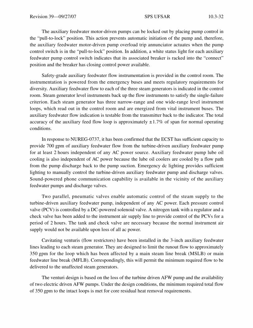
Revision 39—09/27/07 SPS UFSAR 10.3-32
The auxiliary feedwater motor-driven pumps can be locked out by placing pump control inthe “pull-to-lock” position. This action prevents automatic initiation of the pump and, therefore,the auxiliary feedwater motor-driven pump overload trip annunciator actuates when the pumpcontrol switch is in the “pull-to-lock” position. In addition, a white status light for each auxiliaryfeedwater pump control switch indicates that its associated breaker is racked into the “connect”position and the breaker has closing control power available.
Safety-grade auxiliary feedwater flow instrumentation is provided in the control room. Theinstrumentation is powered from the emergency buses and meets regulatory requirements fordiversity. Auxiliary feedwater flow to each of the three steam generators is indicated in the controlroom. Steam generator level instruments back up the flow instruments to satisfy the single-failurecriterion. Each steam generator has three narrow-range and one wide-range level instrumentloops, which read out in the control room and are energized from vital instrument buses. Theauxiliary feedwater flow indication is testable from the transmitter back to the indicator. The totalaccuracy of the auxiliary feed flow loop is approximately ±1.7% of span for normal operatingconditions.
In response to NUREG-0737, it has been confirmed that the ECST has sufficient capacity toprovide 700 gpm of auxiliary feedwater flow from the turbine-driven auxiliary feedwater pumpfor at least 2 hours independent of any AC power source. Auxiliary feedwater pump lube oilcooling is also independent of AC power because the lube oil coolers are cooled by a flow pathfrom the pump discharge back to the pump suction. Emergency dc lighting provides sufficientlighting to manually control the turbine-driven auxiliary feedwater pump and discharge valves.Sound-powered phone communication capability is available in the vicinity of the auxiliaryfeedwater pumps and discharge valves.
Two parallel, pneumatic valves enable automatic control of the steam supply to theturbine-driven auxiliary feedwater pump, independent of any AC power. Each pressure controlvalve (PCV) is controlled by a DC-powered solenoid valve. A nitrogen tank with a regulator and acheck valve has been added to the instrument air supply line to provide control of the PCVs for aperiod of 2 hours. The tank and check valve are necessary because the normal instrument airsupply would not be available upon loss of all ac power.
Cavitating venturis (flow restrictors) have been installed in the 3-inch auxiliary feedwaterlines leading to each steam generator. They are designed to limit the runout flow to approximately350 gpm for the loop which has been affected by a main steam line break (MSLB) or mainfeedwater line break (MFLB). Correspondingly, this will permit the minimum required flow to bedelivered to the unaffected steam generators.
The venturi design is based on the loss of the turbine driven AFW pump and the availabilityof two electric driven AFW pumps. Under the design conditions, the minimum required total flowof 350 gpm to the intact loops is met for core residual heat removal requirements.

Revision 39—09/27/07 SPS UFSAR 10.3-33
Procedures are provided to assist the operators in manually starting the auxiliary feedwatersystem and controlling feed flow to the steam generators under a variety of operating conditions.Since the Surry Power Station has the capability of cross-connecting the two units’ auxiliaryfeedwater systems, procedural guidance is provided on how to utilize the other unit’s auxiliaryfeedwater system, if necessary.
Operability requirements for the auxiliary feedwater system and associated instrumentationare prescribed by the Technical Specifications.
The feedwater piping at the Surry Power Station incorporates several design features toreduce the likelihood of secondary-system fluid flow instability, i.e., water hammer:
1. Loop seals at the feedwater inlets to the steam generators are provided to reduce the length ofpiping that could be filled with steam if the steam generator feedring were to drain into thesteam generator.
2. Top discharge feedwater spargers (J-tubes) reduce the likelihood of feedring drainage. Theflow conditions to which the J-tubes are subjected are not severe, and J-tube stiffness is veryhigh. The design has been evaluated for the expected service conditions and the integrity ofthe attachment weld will be maintained for the expected plant lifetime.
3. A full penetration weld between the steam generator feedwater inlet nozzle and the feedringprevents leakage from the feedring when steam generator water level is below the feedring.
4. The steam generator feedrings are offset approximately 2.5 inches in elevation above thecenter line of the feed nozzle to further delay draining of the feedwater piping.
During normal operation, the water level in the steam generator is maintained above thefeedring and therefore steam cannot enter the feedring to react with cold feedwater. However, inthe event of a transient that results in uncovering the feedring, the design features of the feedringand feedwater piping as discussed above will maintain the feedring full of water while flow to thesteam generator is interrupted. Therefore, these design features preclude draining of the feedringand reduce the possibility of water hammer in the feedwater system.
10.3.5.4 Tests and Inspections
The auxiliary steam generator feedwater pumps and drives are tested in accordance with theTechnical Specifications by admitting steam to the turbine drive or energizing the motor drivers.During these tests, verification of flow from the emergency condensate storage tank to the steamgenerators from each of the auxiliary feedwater pumps verifies proper alignment of the requiredauxiliary feedwater flowpaths. Periodic testing is staggered to test the motor-driven andsteam-driven auxiliary feedwater pumps at different times to reduce the potential for inadvertentlyleaving closed the discharge valves of all pumps after a test. While a periodic test is beingperformed, the affected AFW pump is declared inoperable and the applicable TechnicalSpecification limiting condition for operation is placed in effect.

Revision 39—09/27/07 SPS UFSAR 10.3-34
10.3.6 Condenser
Two single-pass, divided water-box condensers are provided. Each condenses steam fromone of the two low-pressure turbine exhausts, and steam from the turbine steam bypass valves, asdescribed in Section 10.3.1.
10.3.6.1 Design Basis
The design parameters for each condenser are listed in Table 10.3-3.
10.3.6.2 Description
The condensers are of conventional design, manufactured by Ecolaire-Rand Company, andhave a neoprene-lined rubber belt-type expansion joint in the neck. They also have steam andcondensate crossover ducts to equalize pressure, and impingement baffles to protect the tubes.The tubes are made of titanium, which provides relative immunity from tube-enderosion/corrosion and reduces circulating water inleakage. The waterboxes have a 3/16-inchneoprene lining to provide protection and reduce maintenance. The tubesheet material isaluminum-bronze-D, ASTM B171, Alloy 614. In the event that excessive galvanic corrosion isexperienced at the tube/tubesheet interface, an epoxy coating can be added to help minimize anycorrosive effect of the electrochemical potential between the tubes and tubesheets. The material isa nonaging, nonshrinking, non-hygroscopic, nontoxic, non-water solution that will withstandcorrosion, galvanic action, and cavitation. Internal tube support plates are spaced 24 inches apart.One No. 5 feedwater heater and one No. 6 feedwater heater are located in each condenser neck.
The condenser hotwell is of the deaerating type capable of reducing the oxygen content toless than 0.005 cm3/liter. The deaerating capability is necessary, as there is no deaeratingfeedwater heater in the feedwater cycle. Hotwell division plates segregate the condensate fromeach tube bundle, with sample connections provided for each region. Samples are pumped to theturbine building for analysis.
Two twin-element, two-stage, steam jet air ejector units, each complete with tubedinter-condenser and after-condenser, are provided for removing noncondensable gases from thecondenser shells. For normal air removal, one element of each ejector unit is operated percondenser shell. The ejectors function by using auxiliary steam and discharge to the atmosphere.A radiation monitor is installed in the common discharge line from the two air ejectors asdescribed in Section 10.3.8. For initial condenser shell-side air removal, a noncondensing primingejector is provided for each shell. These ejectors function by using steam from the auxiliary steamsystem (Section 10.3.2).
10.3.6.3 Performance Analysis
Loss of normal ac power causes the four 96-inch condenser outlet valves to partially close.This closure permits the minimum flow of circulating water to continue through the condenser forthe main steam bypass system, and conserves water in the intake canal for the recirculation spraycoolers.

Revision 39—09/27/07 SPS UFSAR 10.3-35
10.3.6.4 Tests and Inspections
Circulating water and those service water isolation valves, which are required to close toconserve intake canal inventory following a design basis accident, are periodically verified thatthe total leakage flow from these sources are limited to less than the leakage assumptions of thecanal inventory analysis.
10.3.7 Lubricating Oil System
A pressure lubricating oil system is provided to perform the following functions:
1. Store lubricating oil.
2. Supply oil to and receive oil from the turbine-generator oil reservoir.
3. Purify a side stream of oil from the turbine-generator oil reservoir on a continuous-bypassbasis.
4. Clean and reclaim used oil from the storage tanks, pumping it from the used-oil storage tankvia the purifier to the clean-oil storage tank.
10.3.7.1 Design Basis
The lubricating oil system consists of a 21,000-gallon reservoir, two 22,000-gallonhorizontal all-welded steel storage tanks, an oil purifier, and two identical motor-driven transferpumps. The two gear-type positive displacement transfer pumps are each capable of two-sidedoperation at 108 and 48 gpm to accomplish the various batch cleaning, transfer, and circulatingoperations. The variable speed oil conditioner is rated at 1200–1600 gal/hr.
10.3.7.2 Description
A turbine shaft-driven oil pump normally supplies all lubricating oil requirements to theturbine-generator unit. An ac motor-driven turning gear oil pump is installed for supplyinglubricating oil during start-up, shutdown, and standby conditions. An emergency dc motor-drivenoil pump, operated from the black battery, is also available to ensure lubricating oil to thebearings.
Cooling water from the bearing cooling water system (Section 10.3.9) is used for theturbine lube-oil coolers. The two 22,000-gallon storage tanks are normally designated “clean” and“used,” but are interchangeable and are located inside a fireproof room equipped with watersprays and vent fans. The transfer pumps and piping are arranged so that oil can be processedfrom the oil reservoir or either of the two storage tanks. The processed oil can be returned to eitherof the other two. A vapor extractor purges oil fumes from the reservoir and exhaust to theatmosphere outside of the turbine building. Piping and valves in the system are of welded steel,and high-pressure bearing oil piping is enclosed in a guard pipe.

Revision 39—09/27/07 SPS UFSAR 10.3-36
10.3.7.3 Performance Analysis
The dc motor-driven oil pump is designed to function during a loss of station power tosupply lubricating oil to the turbine-generator bearings. The black battery provides anuninterrupted source of power to this pump.
10.3.7.4 Tests and Inspections
The dc bearing oil pump is tested periodically.
10.3.8 Secondary Vent and Drain Systems
Because the steam and power conversion system is normally nonradioactive, vents anddrains are arranged in much the same manner as those in a fossil-fueled power station. However,because air ejector vents and steam generator blowdown can possibly become contaminated andbecause they discharge to the environment, they are monitored and discharge under controlledconditions as described in Chapter 11.
The air ejector vent subsystem is shown in Reference Drawing 2. The steam generatorblowdown system is shown in Reference Drawing 8.
10.3.8.1 Design Basis
Each of the condenser steam jet air ejectors (two per shell) is designed to remove 12.5 cfmof free air. Each ejector normally uses about 800 lb/hr of steam at a 140 to 200 psig from theauxiliary steam header, while using 900 gpm of condensate for cooling. Separate hogging orvacuum priming jets are used to reduce condenser vacuum to 1 to 3 inches Hg absolute duringstart-up.
10.3.8.2 Description
Generally, secondary plant piping drains to the condenser.
Vent gases removed from the condensers by the air ejectors are normally dischargedthrough a radiation monitor (Section 11.3) to the atmosphere. If a steam generator tube ruptures,with subsequent contamination of the steam, the radioactive noncondensable gases would bedetected by the radiation monitor located in the air ejector effluent line. The related accidentanalysis is covered in Section 14.3.1. When the radioactivity level reaches the alarm setpoint ofthe monitor, trip valves in the air ejector effluent line will automatically actuate to divert theeffluent flow to the containment and shut off the vent to atmosphere. Other vents from the turbinegenerator that handle carbon dioxide, hydrogen, oil vapor, and other nonradioactive gases aredischarged directly to the atmosphere outside the turbine building.
As discussed above, the condenser air ejector discharge line is a potentially radioactiverelease point and is therefore required to have high-range radiation monitoring per therequirements of NUREG-0578, Section 2.1.8.b. For this reason, two manual isolation valves havebeen installed and the air ejector discharge lines have been rerouted to have connections upstream

Revision 39—09/27/07 SPS UFSAR 10.3-37
of ventilation vent no. 2 high-range effluent monitor for use during accident conditions. If acondition were to exist such that a radiation monitor (low range) alarms and the containment isunder a phase I isolation mode, the air ejector isolation valves would shut and secure all flow fromthe air ejector vent. However, this modification provides a method for maintaining condenservacuum, if necessary, by allowing the operator to manually establish condenser-air ejector flowthrough the new discharge line and the high-range vent stack monitor, as well as the low-rangeeffluent monitor. Both of the manual isolation valves are under administrative control. Thehigh-range effluent monitor isolation valve is normally shut and the low-range effluent monitormanual isolation valve is open.
10.3.8.3 Performance Analysis
Loss of power or air causes both diversion valves in the air ejector line to fail closed, thuspreventing possible radioactive contaminants in the condenser steam space from reaching theatmosphere. In addition, the air-operated shut-off valves in the steam supply lines to the airejectors will also go closed on a loss of power or air.
Radiation monitoring and alarm initiation are unaffected by loss of power, but a signal fromthe containment isolation system (Section 5.2) causes the trip valves on the outside of thecontainment wall to close.
10.3.8.4 Tests and Inspections
The vent and drain systems are in continual use and require no special testing andinspection. However, the trip valves installed in these systems, which are part of the containmentisolation system, are tested in accordance with Section 5.2.
10.3.9 Bearing Cooling Water System
The bearing cooling water system supplies cooling water to the steam and power conversionsystem equipment and is a closed cycle system using pumped condensate quality water as coolingwater. The heat removed by the cooling water is transferred to service water in the bearing coolingheat exchangers, as described in Section 9.9. A review of the effects of the power uprate to a corepower of 2546 MWt was conducted and the bearing cooling water system was found to beadequate.
The bearing cooling water system is shown schematically in Figure 10.3-11 and ReferenceDrawing 9.
10.3.9.1 Design Basis
The turbine plant equipment is designed for full load operation with cooling water suppliedat a maximum temperature of 105°F. The bearing cooling water heat exchangers consist of threehalf-size units capable of maintaining the cooling water supply temperature below 105°F at allriver water temperatures.
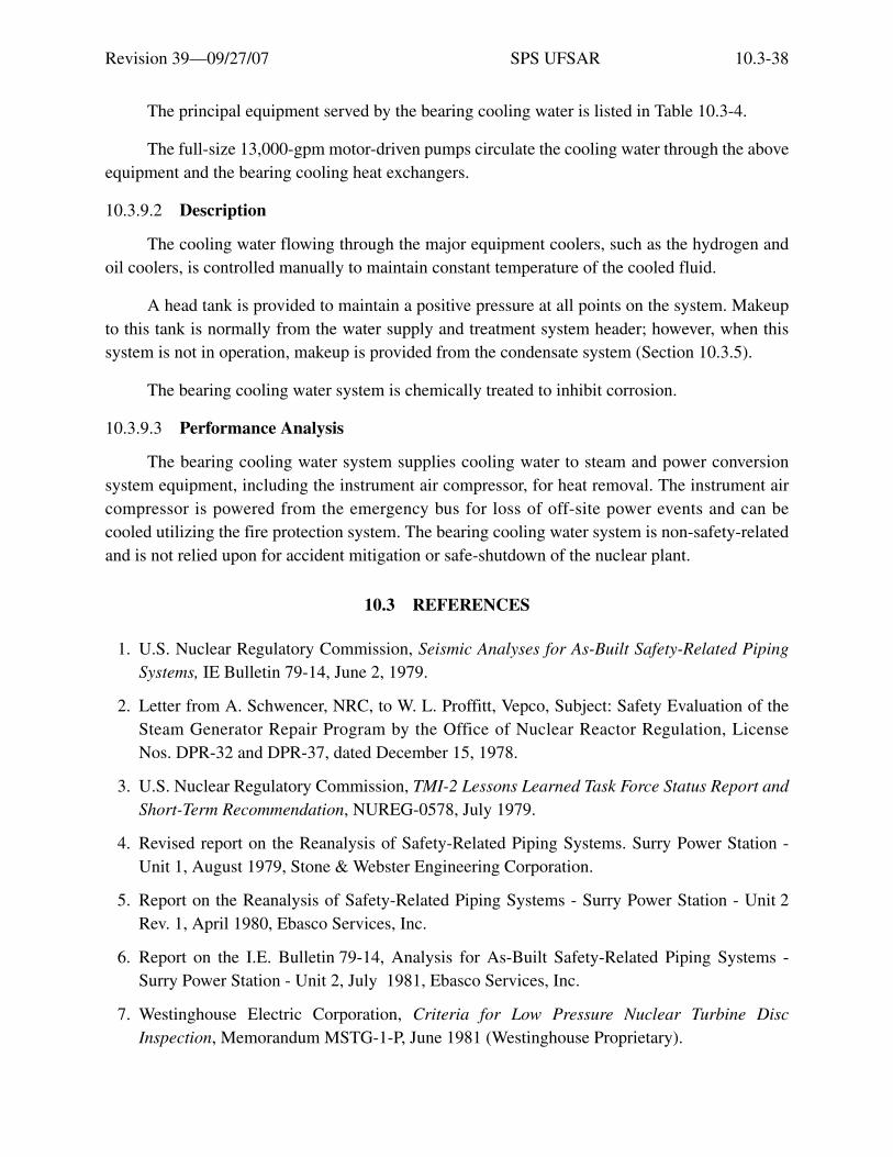
Revision 39—09/27/07 SPS UFSAR 10.3-38
The principal equipment served by the bearing cooling water is listed in Table 10.3-4.
The full-size 13,000-gpm motor-driven pumps circulate the cooling water through the aboveequipment and the bearing cooling heat exchangers.
10.3.9.2 Description
The cooling water flowing through the major equipment coolers, such as the hydrogen andoil coolers, is controlled manually to maintain constant temperature of the cooled fluid.
A head tank is provided to maintain a positive pressure at all points on the system. Makeupto this tank is normally from the water supply and treatment system header; however, when thissystem is not in operation, makeup is provided from the condensate system (Section 10.3.5).
The bearing cooling water system is chemically treated to inhibit corrosion.
10.3.9.3 Performance Analysis
The bearing cooling water system supplies cooling water to steam and power conversionsystem equipment, including the instrument air compressor, for heat removal. The instrument aircompressor is powered from the emergency bus for loss of off-site power events and can becooled utilizing the fire protection system. The bearing cooling water system is non-safety-relatedand is not relied upon for accident mitigation or safe-shutdown of the nuclear plant.
10.3 REFERENCES
1. U.S. Nuclear Regulatory Commission, Seismic Analyses for As-Built Safety-Related PipingSystems, IE Bulletin 79-14, June 2, 1979.
2. Letter from A. Schwencer, NRC, to W. L. Proffitt, Vepco, Subject: Safety Evaluation of theSteam Generator Repair Program by the Office of Nuclear Reactor Regulation, LicenseNos. DPR-32 and DPR-37, dated December 15, 1978.
3. U.S. Nuclear Regulatory Commission, TMI-2 Lessons Learned Task Force Status Report andShort-Term Recommendation, NUREG-0578, July 1979.
4. Revised report on the Reanalysis of Safety-Related Piping Systems. Surry Power Station -Unit 1, August 1979, Stone & Webster Engineering Corporation.
5. Report on the Reanalysis of Safety-Related Piping Systems - Surry Power Station - Unit 2Rev. 1, April 1980, Ebasco Services, Inc.
6. Report on the I.E. Bulletin 79-14, Analysis for As-Built Safety-Related Piping Systems -Surry Power Station - Unit 2, July 1981, Ebasco Services, Inc.
7. Westinghouse Electric Corporation, Criteria for Low Pressure Nuclear Turbine DiscInspection, Memorandum MSTG-1-P, June 1981 (Westinghouse Proprietary).

Revision 39—09/27/07 SPS UFSAR 10.3-39
10.3 REFERENCE DRAWINGS
The list of Station Drawings below is provided for information only. The referenced drawings are not part of the UFSAR. This is not intended to be a complete listing of all Station Drawings referenced from this section of the UFSAR. The contents of Station Drawings are controlled by station procedure.
Drawing Number Description
1. 11448-FM-064A Flow/Valve Operating Numbers Diagram: Main Steam System, Unit 1
11548-FM-064A Flow/Valve Operating Numbers Diagram: Main Steam System, Unit 2
2. 11448-FM-066A Flow/Valve Operating Numbers Diagram: Auxiliary Steam and Air Removal System, Unit 1
11548-FM-066A Flow/Valve Operating Numbers Diagram: Auxiliary Steam and Air Removal System, Unit 2
3. 11448-FM-066B Flow/Valve Operating Numbers Diagram: Auxiliary Steam System, Primary Plant, Unit 1
4. 11448-FM-071A Flow/Valve Operating Numbers Diagram: Circulating and Service Water System, Unit 1
11548-FM-071A Flow/Valve Operating Numbers Diagram: Circulating and Service Water System, Unit 2
5. 11448-FM-067A Flow/Valve Operating Numbers Diagram: Condensate System, Unit 1
11548-FM-067A Flow/Valve Operating Numbers Diagram: Condensate System, Unit 2
6. 11448-FM-068A Flow/Valve Operating Numbers Diagram: Feedwater System, Unit 1
11548-FM-068A Flow/Valve Operating Numbers Diagram: Feedwater System, Unit 2
7. 11448-FM-123A Flow/Valve Operating Numbers Diagram: Chemical Feed Systems, Unit 1
11548-FM-123A Flow/Valve Operating Numbers Diagram: Chemical Feed System, Unit 2

Revision 39—09/27/07 SPS UFSAR 10.3-40
8. 11448-FM-124A Flow/Valve Operating Numbers Diagram: Steam Generator Blowdown Recirculation and Transfer System, Unit 1
11548-FM-124A Flow/Valve Operating Numbers Diagram: Steam Generator Blowdown Recirculation and Transfer System, Unit 2
9. 11448-FM-23A Flow Diagram: Bearing Cooling Water System, Unit 1
11548-FM-23A Flow Diagram: Bearing Cooling Water System, Unit 2
10. 11448-FM-59M Heat Balance Diagram: 100% Core Power, Unit 1
11548-FM-59A Heat Balance Diagram: 100% Core Power, Unit 2
Drawing Number Description

Revision 39—09/27/07 SPS UFSAR 10.3-41
Table 10.3-1STEAM GENERATOR BLOWDOWN SYSTEMS - CODES AND STANDARDS
Component Codes and Standards
Heat exchanger ASME Code, Section VIII, Division 1
Piping and fittings ANSI B31.1, Code for Pressure Piping, Power Piping, 1967
Valves ANSI B16.5, Flanged Valves, 1973
Instrumentation and controls ISA Standards and Practices for Instrumentation (1974)
Table 10.3-2CONDENSATE POLISHER SYSTEM DESIGN AND OPERATING INFORMATION
Design pressure 690 psigNormal pressure 505-590 psigDesign flow 14,515 gpmNormal flow per demineralizer 2420 gpmDesign temperature 135°FNormal temperature 75-125°FNumber of demineralizers 6 (+l standby)Number of demineralizers used at 100% power 6Number of regenerations per day 1Water used per regeneration Approximately 50,000 gal
Table 10.3-3CONDENSER DESIGN PARAMETERS
Steam condensed 6,195,000 lb/hrCirculating water 773,000 gpmSurface 650,870 ft2
Number of tubes 71,328Tube material 22 BWG titaniumTube o.d. 7/8 in.Effective length 39 ft. 10 in.Backpressure 3.29 in. HgHeat load, Btu/hr at 90°F 5.807 × 10⁹
Tube water velocity 6.6 ft/sec

Revision 39—09/27/07 SPS UFSAR 10.3-42
Table 10.3-4EQUIPMENT SUPPLIED BY BEARING COOLING WATER SYSTEM
Equipment Design Flow, gpmGenerator hydrogen coolers 6048Hydrogen seal-oil coolers 360Turbine oil coolers 3380Exciter cooler 300Isolated-phase bus duct air coolers 167Instrument air compressors 21Condensate, feed, and heater drain pumps 334Sample coolers and chillers for S/G on linechemistry monitoring system
154 (each unit)
Central chillers 1300 (each)Vacuum priming sealwater coolers 100 (each)

Revision 39—09/27/07 SPS UFSAR 10.3-43
Figu
re 1
0.3-
1 M
AIN
ST
EA
M S
YST
EM
Etia
m v
enen
atis
acc
umsa
n en
im. M
auris
rut
rum
, dia
m q
uis
tinci
dunt
ele
men
tum
, sem
orc
i bib
endu
m li
bero
, ut e
lem
entu
m
just
o m
agna
at a
ugue
. Aliq
uam
sap
ien
mas
sa, f
auci
bus
ac, e
lem
entu
m n
on, l
aore
et n
ec, f
elis
. Ves
tibul
um a
ccum
san
sagi
ttis
ipsu
m. I
n ul
lam
corp
er, d
ui s
ed c
ursu
s eu
ism
od, a
nte
wis
i dap
ibus
ligu
la, i
d rh
oncu
s ip
sum
mi a
t tel
lus.
Cla
ss a
pten
t ta
citi
soci
osqu
ad
litor
a to
rque
nt p
er c
onub
ia n
ostr
a, p
er in
cept
os h
ymen
aeos
. Qui
sque
rho
ncus
wis
i vita
e do
lor.
Etia
m
elei
fend
. Int
eger
impe
rdie
t veh
icul
a an
te. S
ed in
arc
u et
odi
o ac
cum
san
port
a. A
enea
n m
i. V
ivam
us n
on o
rci v
itae
urna
al
ique
t ulla
mco
rper
. Cla
ss a
pten
t tac
iti s
ocio
squ
ad li
tora
torq
uent
per
con
ubia
nos
tra,
per
ince
ptos
hym
enae
os. I
n fr
ingi
lla
ligul
a ve
l odi
o. In
hac
hab
itass
e pl
atea
dic
tum
st. E
tiam
tem
pus
lacu
s ac
arc
u. P
raes
ent n
on li
bero
.

Revision 39—09/27/07 SPS UFSAR 10.3-44
Figure 10.3-2 SERIES 51 STEAM GENERATOR

Revision 39—09/27/07 SPS UFSAR 10.3-45
Figure 10.3-3 STEAM GENERATOR LOWER ASSEMBLY

Revision 39—09/27/07 SPS UFSAR 10.3-46
Figure 10.3-4 QUATREFOIL TUBE SUPPORT PLATE
Revision 39—09/27/07 SPS UFSAR 10.3-47
Figure 10.3-5 TYPICAL SLUDGE REMOVAL SYSTEM
Revision 39—09/27/07 SPS UFSAR 10.3-48
Figure 10.3-6 TYPICAL WET LAYUP SYSTEM

Revision 39—09/27/07 SPS UFSAR 10.3-49
Figu
re 1
0.3-
7 A
UX
ILIA
RY
ST
EA
M S
YST
EM
Etia
m v
enen
atis
acc
umsa
n en
im. M
auris
rut
rum
, dia
m q
uis
tinci
dunt
ele
men
tum
, sem
orc
i bib
endu
m li
bero
, ut e
lem
entu
m
just
o m
agna
at a
ugue
. Aliq
uam
sap
ien
mas
sa, f
auci
bus
ac, e
lem
entu
m n
on, l
aore
et n
ec, f
elis
. Ves
tibul
um a
ccum
san
sagi
ttis
ipsu
m. I
n ul
lam
corp
er, d
ui s
ed c
ursu
s eu
ism
od, a
nte
wis
i dap
ibus
ligu
la, i
d rh
oncu
s ip
sum
mi a
t tel
lus.
Cla
ss a
pten
t ta
citi
soci
osqu
ad
litor
a to
rque
nt p
er c
onub
ia n
ostr
a, p
er in
cept
os h
ymen
aeos
. Qui
sque
rho
ncus
wis
i vita
e do
lor.
Etia
m
elei
fend
. Int
eger
impe
rdie
t veh
icul
a an
te. S
ed in
arc
u et
odi
o ac
cum
san
port
a. A
enea
n m
i. V
ivam
us n
on o
rci v
itae
urna
al
ique
t ulla
mco
rper
. Cla
ss a
pten
t tac
iti s
ocio
squ
ad li
tora
torq
uent
per
con
ubia
nos
tra,
per
ince
ptos
hym
enae
os. I
n fr
ingi
lla
ligul
a ve
l odi
o. In
hac
hab
itass
e pl
atea
dic
tum
st. E
tiam
tem
pus
lacu
s ac
arc
u. P
raes
ent n
on li
bero
.

Revision 39—09/27/07 SPS UFSAR 10.3-50
Figu
re 1
0.3-
8 C
ON
DE
NSA
TE
SY
STE
M
Etia
m v
enen
atis
acc
umsa
n en
im. M
auris
rut
rum
, dia
m q
uis
tinci
dunt
ele
men
tum
, sem
orc
i bib
endu
m li
bero
, ut e
lem
entu
m
just
o m
agna
at a
ugue
. Aliq
uam
sap
ien
mas
sa, f
auci
bus
ac, e
lem
entu
m n
on, l
aore
et n
ec, f
elis
. Ves
tibul
um a
ccum
san
sagi
ttis
ipsu
m. I
n ul
lam
corp
er, d
ui s
ed c
ursu
s eu
ism
od, a
nte
wis
i dap
ibus
ligu
la, i
d rh
oncu
s ip
sum
mi a
t tel
lus.
Cla
ss a
pten
t ta
citi
soci
osqu
ad
litor
a to
rque
nt p
er c
onub
ia n
ostr
a, p
er in
cept
os h
ymen
aeos
. Qui
sque
rho
ncus
wis
i vita
e do
lor.
Etia
m
elei
fend
. Int
eger
impe
rdie
t veh
icul
a an
te. S
ed in
arc
u et
odi
o ac
cum
san
port
a. A
enea
n m
i. V
ivam
us n
on o
rci v
itae
urna
al
ique
t ulla
mco
rper
. Cla
ss a
pten
t tac
iti s
ocio
squ
ad li
tora
torq
uent
per
con
ubia
nos
tra,
per
ince
ptos
hym
enae
os. I
n fr
ingi
lla
ligul
a ve
l odi
o. In
hac
hab
itass
e pl
atea
dic
tum
st. E
tiam
tem
pus
lacu
s ac
arc
u. P
raes
ent n
on li
bero
.
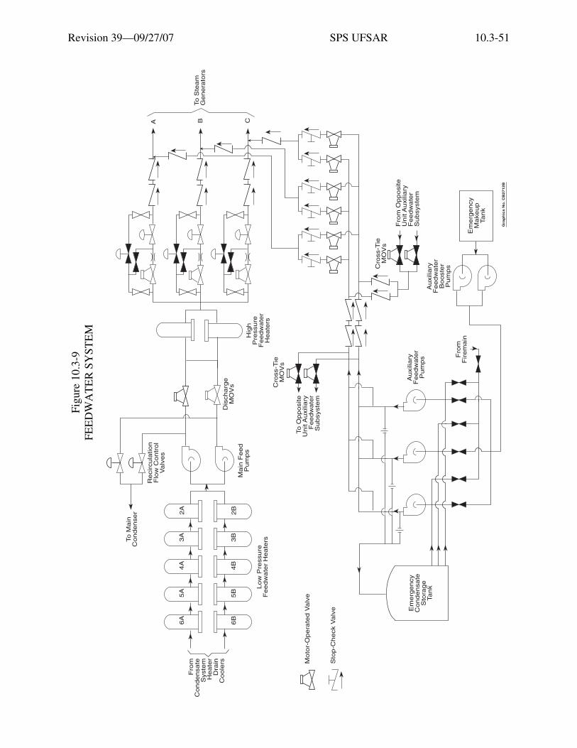
Revision 39—09/27/07 SPS UFSAR 10.3-51
Figu
re 1
0.3-
9 FE
ED
WA
TE
R S
YST
EM
Etia
m v
enen
atis
acc
umsa
n en
im. M
auris
rut
rum
, dia
m q
uis
tinci
dunt
ele
men
tum
, sem
orc
i bib
endu
m li
bero
, ut e
lem
entu
m
just
o m
agna
at a
ugue
. Aliq
uam
sap
ien
mas
sa, f
auci
bus
ac, e
lem
entu
m n
on, l
aore
et n
ec, f
elis
. Ves
tibul
um a
ccum
san
sagi
ttis
ipsu
m. I
n ul
lam
corp
er, d
ui s
ed c
ursu
s eu
ism
od, a
nte
wis
i dap
ibus
ligu
la, i
d rh
oncu
s ip
sum
mi a
t tel
lus.
Cla
ss a
pten
t ta
citi
soci
osqu
ad
litor
a to
rque
nt p
er c
onub
ia n
ostr
a, p
er in
cept
os h
ymen
aeos
. Qui
sque
rho
ncus
wis
i vita
e do
lor.
Etia
m
elei
fend
. Int
eger
impe
rdie
t veh
icul
a an
te. S
ed in
arc
u et
odi
o ac
cum
san
port
a. A
enea
n m
i. V
ivam
us n
on o
rci v
itae
urna
al
ique
t ulla
mco
rper
. Cla
ss a
pten
t tac
iti s
ocio
squ
ad li
tora
torq
uent
per
con
ubia
nos
tra,
per
ince
ptos
hym
enae
os. I
n fr
ingi
lla
ligul
a ve
l odi
o. In
hac
hab
itass
e pl
atea
dic
tum
st. E
tiam
tem
pus
lacu
s ac
arc
u. P
raes
ent n
on li
bero
.
Gra
ph
ics
No
. C
B2
71
2B
6A
5A
4A
3A
2A
6B
5B
4B
3B
2B
Low
Pre
ssure
Feedw
ate
r H
eate
rs
Fro
mC
ondensate
Syste
mH
eate
rD
rain
Coole
rs
Main
Feed
Pum
ps
Dis
charg
eM
OV
s
To S
team
Genera
tors
Hig
hP
ressure
Feedw
ate
rH
eate
rs
A B C
Em
erg
ency
Condensate
Sto
rage
Tank
Recircula
tion
Flo
w C
ontr
ol
Valv
es
To M
ain
Condenser
To O
pposite
Unit A
uxilia
ryF
eedw
ate
rS
ubsyste
m
Cro
ss-T
ieM
OV
s
Cro
ss-T
ieM
OV
s
Fro
m O
pposite
Unit A
uxilia
ryF
eedw
ate
rS
ubsyste
m
Em
erg
ency
Makeup
Tank
Auxilia
ryF
eedw
ate
rB
ooste
rP
um
ps
Fro
mF
irem
ain
Auxilia
ryF
eedw
ate
rP
um
ps
Moto
r-O
pera
ted V
alv
e
Sto
p-C
heck V
alv
e
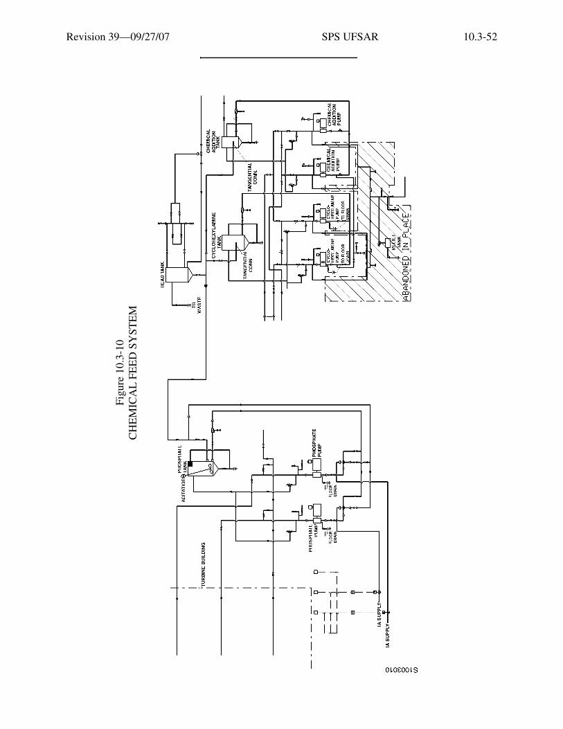
Revision 39—09/27/07 SPS UFSAR 10.3-52
Figu
re 1
0.3-
10
CH
EM
ICA
L F
EE
D S
YST
EM
Etia
m v
enen
atis
acc
umsa
n en
im. M
auris
rut
rum
, dia
m q
uis
tinci
dunt
ele
men
tum
, sem
orc
i bib
endu
m li
bero
, ut e
lem
entu
m
just
o m
agna
at a
ugue
. Aliq
uam
sap
ien
mas
sa, f
auci
bus
ac, e
lem
entu
m n
on, l
aore
et n
ec, f
elis
. Ves
tibul
um a
ccum
san
sagi
ttis
ipsu
m. I
n ul
lam
corp
er, d
ui s
ed c
ursu
s eu
ism
od, a
nte
wis
i dap
ibus
ligu
la, i
d rh
oncu
s ip
sum
mi a
t tel
lus.
Cla
ss a
pten
t ta
citi
soci
osqu
ad
litor
a to
rque
nt p
er c
onub
ia n
ostr
a, p
er in
cept
os h
ymen
aeos
. Qui
sque
rho
ncus
wis
i vita
e do
lor.
Etia
m
elei
fend
. Int
eger
impe
rdie
t veh
icul
a an
te. S
ed in
arc
u et
odi
o ac
cum
san
port
a. A
enea
n m
i. V
ivam
us n
on o
rci v
itae
urna
al
ique
t ulla
mco
rper
. Cla
ss a
pten
t tac
iti s
ocio
squ
ad li
tora
torq
uent
per
con
ubia
nos
tra,
per
ince
ptos
hym
enae
os. I
n fr
ingi
lla
ligul
a ve
l odi
o. In
hac
hab
itass
e pl
atea
dic
tum
st. E
tiam
tem
pus
lacu
s ac
arc
u. P
raes
ent n
on li
bero
.

Revision 39—09/27/07 SPS UFSAR 10.3-53
Figu
re 1
0.3-
11 (
SHE
ET
1 O
F 2)
BE
AR
ING
CO
OL
ING
SY
STE
M
Etia
m v
enen
atis
acc
umsa
n en
im. M
auris
rut
rum
, dia
m q
uis
tinci
dunt
ele
men
tum
, sem
orc
i bib
endu
m li
bero
, ut e
lem
entu
m
just
o m
agna
at a
ugue
. Aliq
uam
sap
ien
mas
sa, f
auci
bus
ac, e
lem
entu
m n
on, l
aore
et n
ec, f
elis
. Ves
tibul
um a
ccum
san
sagi
ttis
ipsu
m. I
n ul
lam
corp
er, d
ui s
ed c
ursu
s eu
ism
od, a
nte
wis
i dap
ibus
ligu
la, i
d rh
oncu
s ip
sum
mi a
t tel
lus.
Cla
ss a
pten
t ta
citi
soci
osqu
ad
litor
a to
rque
nt p
er c
onub
ia n
ostr
a, p
er in
cept
os h
ymen
aeos
. Qui
sque
rho
ncus
wis
i vita
e do
lor.
Etia
m
elei
fend
. Int
eger
impe
rdie
t veh
icul
a an
te. S
ed in
arc
u et
odi
o ac
cum
san
port
a. A
enea
n m
i. V
ivam
us n
on o
rci v
itae
urna
al
ique
t ulla
mco
rper
. Cla
ss a
pten
t tac
iti s
ocio
squ
ad li
tora
torq
uent
per
con
ubia
nos
tra,
per
ince
ptos
hym
enae
os. I
n fr
ingi
lla
ligul
a ve
l odi
o. In
hac
hab
itass
e pl
atea
dic
tum
st. E
tiam
tem
pus
lacu
s ac
arc
u. P
raes
ent n
on li
bero
.
* **
*
Sh
ee
t 2
F G
LC
V
TC
V
Fro
m W
ate
r S
up
ply
an
d T
rea
tme
nt
Syste
m H
ea
de
r
Re
circ to
Co
nd
en
sa
te
To
Oth
er
Un
itB
ea
rin
g C
oo
ling
To
Co
mp
on
en
t C
oo
ling
Su
rge
To
Va
cu
um
Prim
ing
To
6th
Po
int
He
ate
r L
oo
pse
als
Su
ctio
n f
rom
Co
nd
en
sa
teA
lte
rna
teM
ake
up
Pu
mp
Ge
ne
rato
r H
2 C
oo
lers
H2 S
ea
l O
ilU
nit C
oo
lers T
CV
TC
VIs
ola
ted
Ph
ase
Bu
s D
uct A
irC
oo
lers
H2 G
as D
rye
rH
ea
t E
xch
an
ge
r
Instr
um
en
tA
ir C
om
pre
sso
rA
fte
rco
ole
r
To
Oth
er
Un
itB
ea
rin
gC
oo
ling
To
Oth
er
Un
itB
ea
rin
gC
oo
ling
Inb
oa
rdE
xcite
rC
oo
lers
Ou
tbo
ard
Excite
rC
oo
lers
Co
nd
en
sa
te P
um
ps
Em
erg
en
cy
Co
olin
gF
rom
Fire
Ma
in
To
Oth
er
Un
itB
ea
rin
gC
oo
ling
Ce
ntr
al
Ch
ille
rs **
VP
Se
alw
ate
rC
oo
lers
Le
ge
nd
EH
CE
lectr
oh
yd
rau
lic C
on
tro
lH
PH
igh
Pre
ssu
reL
CV
Le
ve
l C
on
tro
l V
alv
eL
PL
ow
Pre
ssu
reP
CV
Pre
ssu
re C
on
tro
l V
alv
eT
CV
Te
mp
era
ture
Co
ntr
ol V
alv
eTo
/Fro
m S
am
ple
Co
ole
rsU
nit 2
ha
s 1
Ch
ille
r* **
Gra
ph
ics
No
: P
C88
7
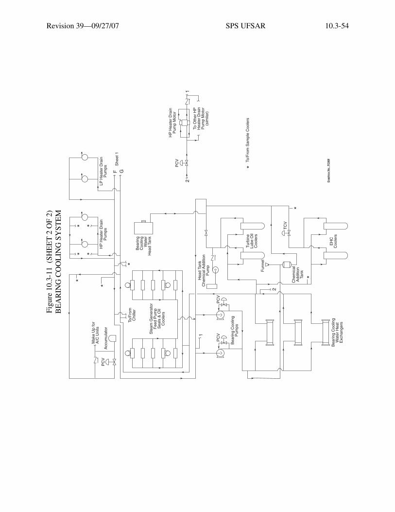
Revision 39—09/27/07 SPS UFSAR 10.3-54
Figu
re 1
0.3-
11 (
SHE
ET
2 O
F 2)
BE
AR
ING
CO
OL
ING
SY
STE
M
Etia
m v
enen
atis
acc
umsa
n en
im. M
auris
rut
rum
, dia
m q
uis
tinci
dunt
ele
men
tum
, sem
orc
i bib
endu
m li
bero
, ut e
lem
entu
m
just
o m
agna
at a
ugue
. Aliq
uam
sap
ien
mas
sa, f
auci
bus
ac, e
lem
entu
m n
on, l
aore
et n
ec, f
elis
. Ves
tibul
um a
ccum
san
sagi
ttis
ipsu
m. I
n ul
lam
corp
er, d
ui s
ed c
ursu
s eu
ism
od, a
nte
wis
i dap
ibus
ligu
la, i
d rh
oncu
s ip
sum
mi a
t tel
lus.
Cla
ss a
pten
t ta
citi
soci
osqu
ad
litor
a to
rque
nt p
er c
onub
ia n
ostr
a, p
er in
cept
os h
ymen
aeos
. Qui
sque
rho
ncus
wis
i vita
e do
lor.
Etia
m
elei
fend
. Int
eger
impe
rdie
t veh
icul
a an
te. S
ed in
arc
u et
odi
o ac
cum
san
port
a. A
enea
n m
i. V
ivam
us n
on o
rci v
itae
urna
al
ique
t ulla
mco
rper
. Cla
ss a
pten
t tac
iti s
ocio
squ
ad li
tora
torq
uent
per
con
ubia
nos
tra,
per
ince
ptos
hym
enae
os. I
n fr
ingi
lla
ligul
a ve
l odi
o. In
hac
hab
itass
e pl
atea
dic
tum
st. E
tiam
tem
pus
lacu
s ac
arc
u. P
raes
ent n
on li
bero
.
*
*
*
* *
*
*
*
*
Ma
ke
Up
fo
rA
/C U
nits
Accu
mu
lato
rP
CV
To
/Fro
mC
hill
er
Ste
am
Ge
ne
rato
rF
ee
d P
um
pS
ea
ls &
Oil
Co
ole
rs
Be
arin
gC
oo
ling
Wa
ter
He
ad
Ta
nk
HP
He
ate
r D
rain
Pu
mp
sL
P H
ea
ter
Dra
inP
um
ps
F GS
he
et
1
2
PC
V
HP
He
ate
r D
rain
Pu
mp
Mo
tor
To
Oth
er
HP
He
ate
r D
rain
Pu
mp
Mo
tor
(sim
ilar)
He
ad
Ta
nk
Ch
em
ica
l Ad
ditio
nP
um
p
PC
VP
CV1
Be
arin
g C
oo
ling
Pu
mp
s
Fu
nn
el
Tu
rbin
eL
ub
e O
ilC
oo
lers
TC
V
2
Ch
em
ica
lA
dd
itio
nTa
nk
Be
arin
g C
oo
ling
Wa
ter
He
at
Exch
an
ge
rs
EH
CC
oo
lers
*To
/Fro
m S
am
ple
Co
ole
rs
1
Gra
ph
ics
No
: P
C88
8