chapter 11 ethernet ports - arista networks · ethernet frames transmitted by the switch are...
TRANSCRIPT

527
Chapter 11
Ethernet PortsThis chapter describes Ethernet ports supported by Arista switches. Sections covered in this chapterinclude:
• Section 11.1: Ethernet Ports Introduction
• Section 11.2: Ethernet Standards
• Section 11.3: Ethernet Physical Layer
• Section 11.4: Interfaces
• Section 11.5: Ethernet Configuration Procedures
• Section 11.6: Ethernet Configuration Commands
11.1 Ethernet Ports IntroductionArista switches support a variety of Ethernet network interfaces. This chapter describes theconfiguration and monitoring options available in Arista switching platforms.
11.2 Ethernet StandardsEthernet, standardized in IEEE 802.3, is a group of technologies used for communication over localarea networks. Ethernet communication divides data streams into frames containing addresses(source and destination), payload, and cyclical redundancy check (CRC) information.
IEEE 802.3 also describes two types of optical fiber: single-mode fiber (SMF) and multi-mode fiber(MMF).
• SMF is more expensive, but can be used over longer distances (over 300 meters).
• MMF is less expensive, but can only be used over distances of less than 300 meters.
11.2.1 100 Gigabit Ethernet
The 100 Gigabit Ethernet (100GbE) standard defines an Ethernet implementation with a nominal datarate of 100 billion bits per second over multiple 10 gigabit lanes. 100 Gigabit Ethernet implements fullduplex point to point links connected by network switches. Arista switches support 100GBASE-10SRthrough MXP ports.

528
Ethernet Standards Chapter 11: Ethernet Ports
11.2.2 40 Gigabit Ethernet
The 40 Gigabit Ethernet (40GbE) standard defines an Ethernet implementation with a nominal datarate of 40 billion bits per second over multiple 10 gigabit lanes. 40 Gigabit Ethernet implements fullduplex point to point links connected by network switches. 40 gigabit Ethernet standards are named40GBASE-xyz, as interpreted by Table 11-1.
11.2.3 10 Gigabit Ethernet
The 10 Gigabit Ethernet (10GbE) standard defines an Ethernet implementation with a nominal datarate of 10 billion bits per second. 10 Gigabit Ethernet implements full duplex point to point linksconnected by network switches. Half duplex operation, hubs and CSMA/CD do not exist in 10GbE. Thestandard encompasses several PHY standards; a networking device may support different PHY typesthrough pluggable PHY modules. 10GbE standards are named 10GBASE-xyz, as interpreted by Table11-2.
11.2.4 Gigabit Ethernet
The Gigabit Ethernet (GbE), defined by IEEE 802.3-2008, describes an Ethernet version with anominal data rate of one billion bits per second. GbE cables and equipment are similar to those usedin previous standards. While full-duplex links in switches is the typical implementation, the specificationpermits half-duplex links connected through hubs.
Gigabit Ethernet physical layer standards that Arista switches support include 1000BASE-X (opticalfiber), 1000BASE-T (twisted pair cable), and 1000BASE-CX (balanced copper cable).
• 1000BASE-SX is a fiber optic standard that utilizes multi-mode fiber supporting 770 to 860 nm,near infrared (NIR) light wavelength to transmit data over distances ranging from 220 to 550meters. 1000BASE-SX is typically used for intra-building links in large office buildings, co-locationfacilities and carrier neutral Internet exchanges.
• 1000BASE-LX is a fiber standard that utilizes a long wavelength laser (1,270–1,355 nm), with aRMS spectral width of 4 nm to transmit data up to 5 km. 1000BASE-LX can run on all commontypes of multi-mode fiber with a maximum segment length of 550 m.
Table 11-1 40GBASE-xyz Interpretation
x y z
Non-fiber media type, or fiberwavelength
PHY encoding Number of WWDM wavelengths or XAUILanes
C = CopperF = Serial SMFK = BackplaneL = Long (1310 nm)S = Short (850 nm)
R = LAN PHY (64B/66B) No value = 1 (serial)4 = 4 WWDM wavelengths or XAUI Lanes
Table 11-2 10GBASE-xyz Interpretation
x y z
media type or wavelength, ifmedia type is fiber
PHY encoding type Number of WWDM wavelengths or XAUILanes
C = Copper (twin axial)T = Twisted PairS = Short (850 nm)L = Long (1310 nm)E = Extended (1550 nm)Z = Ultra extended (1550 nm)
R = LAN PHY (64B/66B)X = LAN PHY (8B/10B)W = WAN PHY(*) (64B/66B)
If omitted, value = 1 (serial)4 = 4 WWDM wavelengths or XAUI Lanes

Chapter 11: Ethernet Ports Ethernet Standards
529
• 1000BASE-T is a standard for gigabit Ethernet over copper wiring. Each 1000BASE-T networksegment can be a maximum length of 100 meters.
11.2.5 10/100/1000 BASE-T
Arista switches provide 10/100/1000 BASE-T Mbps Ethernet out of band management ports.Auto-negotiation is enabled on these interfaces. Speed (10/100/1000), duplex (half/full), and flowcontrol settings are available using the appropriate speed forced and flowcontrol commands.
11.2.6 Power over Ethernet (PoE)
Selected Arista switches provide power over Ethernet (PoE) to power connected devices. Arista’s PoEimplementation is compliant with IEEE standards 802.3af and 802.3at, and includes partial support for802.3bt. When a standards-compliant powered device (PD) is connected to a PoE-enabled Ethernetport, it is recognized by a specific resistor signature, and its power class is determined by hardwarenegotiation; more granular power adjustments can then be managed by Link Layer Discovery Protocol(LLDP).
11.2.7 Link Fault Signaling
Link Fault Signaling (LFS) is a mechanism by which remote link faults are transmitted to the peer overthe link that is experiencing problems by configuring specific actions. LFS operates between the remoteReconciliation Sublayer (remote RS) and the local Reconciliation Sublayer (local RS). Faults that aredetected between the remote RS and the local RS are treated by the local RS as Local Faults.
LFS enables monitoring FCS and Symbol errors on an interface and if they exceed a configuredthreshold, one of the following three actions are enabled.
• Disable the error on the interface
• Generate system log messages
• Generate a link fault

530
Ethernet Physical Layer Chapter 11: Ethernet Ports
11.3 Ethernet Physical LayerThe Ethernet physical layer (PHY) includes hardware components connecting a switch’s MAC layer tothe transceiver, cable, and ultimately a peer link partner. Data exist in digital form at the MAC layer. Onthe line side of the PHY, data exist as analog signals: light blips on optical fiber or voltage pulses oncopper cable. Signals may be distorted while in transit and recovery may require signal processing.
Ethernet physical layer components include a PHY and a transceiver.
11.3.1 PHYs
The PHY provides translation services between the MAC layer and transceiver. It also helps toestablish links between the local MAC layer and peer devices by detecting and signaling faultconditions. The PHY line-side interface receives Ethernet frames from the link partner as analogwaveforms. The PHY uses signal processing to recover the encoded bits, then sends them to the MAClayer.
PHY line-side interface components and their functions include:
• Physical Medium Attachment (PMA): Framing, octet synchronization, scrambling / descrambling.
• Physical Medium Dependent (PMD): Consists of the transceiver.
• Physical Coding Sublayer (PCS): Performs auto-negotiation and coding (8B/10B or 64B/66B).
The MAC sublayer of the PHY provides a logical connection between the MAC layer and the peerdevice by initializing, controlling, and managing the connection with the peer.
Ethernet frames transmitted by the switch are received by the PHY system-side interface as asequence of digital bits. The PHY encodes them into a media-specific waveform for transmissionthrough the line-side interface and transceiver to the link peer. This encoding may include signalprocessing, such as signal pre-distortion and forward error correction.
PHY system-side interface components and their functions include:
• 10 Gigabit Attachment Unit Interface (XAUI): Connects an Ethernet MAC to a 10 G PHY.
• Serial Gigabit Media Independent Attachment (SGMII): Connects an Ethernet MAC to a 1G PHY.
11.3.2 Transceivers
A transceiver connects the PHY to an external cable (optical fiber or twisted-pair copper) and througha physical connector (LC jack for fiber or RJ-45 jack for copper).
• Optical transceivers convert the PHY signal into light pulses that are sent through optical fiber.
• Copper transceivers connect the PHY to twisted-pair copper cabling.
Arista Small Form-Factor Pluggable (SFP+) and Quad Small Form Factor Pluggable (QSFP+) modulesand cables provide high-density, low-power Ethernet connectivity over fiber and copper media. Aristaoffers transceivers that span data rates, media types, and transmission distances.
Arista 10 Gigabit Ethernet SFP+ Modules:
• 10GBASE-SR (Short Reach)
• Link length maximum 300 meters over multi-mode fiber.
• Optical interoperability with 10GBASE-SRL.
• 10GBASE-SRL (Short Reach Lite)
• Link length maximum 100 meters over multi-mode fiber.
• Optical interoperability with 10GBASE-SR.
Chapter 11: Ethernet Ports Ethernet Physical Layer
531
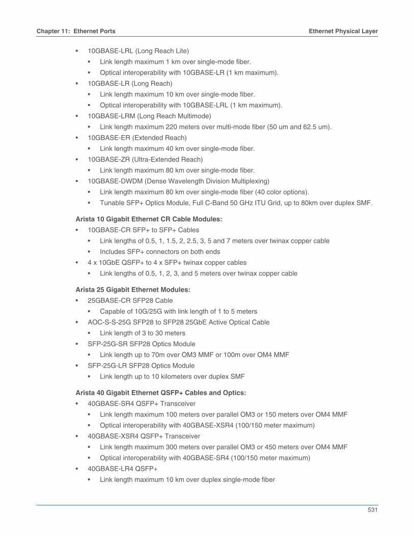
• 10GBASE-LRL (Long Reach Lite)
• Link length maximum 1 km over single-mode fiber.
• Optical interoperability with 10GBASE-LR (1 km maximum).
• 10GBASE-LR (Long Reach)
• Link length maximum 10 km over single-mode fiber.
• Optical interoperability with 10GBASE-LRL (1 km maximum).
• 10GBASE-LRM (Long Reach Multimode)
• Link length maximum 220 meters over multi-mode fiber (50 um and 62.5 um).
• 10GBASE-ER (Extended Reach)
• Link length maximum 40 km over single-mode fiber.
• 10GBASE-ZR (Ultra-Extended Reach)
• Link length maximum 80 km over single-mode fiber.
• 10GBASE-DWDM (Dense Wavelength Division Multiplexing)
• Link length maximum 80 km over single-mode fiber (40 color options).
• Tunable SFP+ Optics Module, Full C-Band 50 GHz ITU Grid, up to 80km over duplex SMF.
Arista 10 Gigabit Ethernet CR Cable Modules:
• 10GBASE-CR SFP+ to SFP+ Cables
• Link lengths of 0.5, 1, 1.5, 2, 2.5, 3, 5 and 7 meters over twinax copper cable
• Includes SFP+ connectors on both ends
• 4 x 10GbE QSFP+ to 4 x SFP+ twinax copper cables
• Link lengths of 0.5, 1, 2, 3, and 5 meters over twinax copper cable
Arista 25 Gigabit Ethernet Modules:
• 25GBASE-CR SFP28 Cable
• Capable of 10G/25G with link length of 1 to 5 meters
• AOC-S-S-25G SFP28 to SFP28 25GbE Active Optical Cable
• Link length of 3 to 30 meters
• SFP-25G-SR SFP28 Optics Module
• Link length up to 70m over OM3 MMF or 100m over OM4 MMF
• SFP-25G-LR SFP28 Optics Module
• Link length up to 10 kilometers over duplex SMF
Arista 40 Gigabit Ethernet QSFP+ Cables and Optics:
• 40GBASE-SR4 QSFP+ Transceiver
• Link length maximum 100 meters over parallel OM3 or 150 meters over OM4 MMF
• Optical interoperability with 40GBASE-XSR4 (100/150 meter maximum)
• 40GBASE-XSR4 QSFP+ Transceiver
• Link length maximum 300 meters over parallel OM3 or 450 meters over OM4 MMF
• Optical interoperability with 40GBASE-SR4 (100/150 meter maximum)
• 40GBASE-LR4 QSFP+
• Link length maximum 10 km over duplex single-mode fiber

532
Ethernet Physical Layer Chapter 11: Ethernet Ports
• 40GBASE-CR4 QSFP+ to QSFP+ twinax copper cables
• Link lengths of 1, 2, 3, 5 and 7 meters over twinax copper cable
• 40G-SRBD Bidirectional QSFP+ Optic
• Link length maximum up to 100 meters over parallel OM3 or 150 meters over OM4 MMF
• 40G Univ QSFP+ Optic
• Link length maximum up to 150 meters over duplex OM3/OM4 and 500 meters over duplexSMF
• 40GBASE-LRL QSFP+ Optic
• Link length maximum up to 1 kilometer over duplex SMF
• 40GBASE-PLRL4 QSFP+ Optic
• Link length maximum up to 1 kilometer over parallel SMF (4x10G LR up to 1 km)
• 40GBASE-PLR4 QSFP+ Optic
• Link length maximum up to 1 kilometer over parallel SMF (4x10G LR up to 1 km)
• 40GBASE-ER QSFP+ Optic
• Link length maximum up to 40 kilometers duplex SMF
Arista Gigabit Ethernet SFP Options:
• 1000BASE-SX (Short Haul)
• Multi-mode fiber
• Link length maximum 550 meter
• 1000BASE-LX (Long Haul)
• Single-mode fiber
• Link length maximum 10 km (single mode)
• 1000BASE-T (RJ-45 Copper)
• Category 5 cabling
• Full duplex 1000Mbps connectivity
Arista 100 Gigabit Ethernet QSFP Modules:
• 100GBASE-SR4 QSFP transceiver
• Link length up to 70 meters over parallel OM3 or 100 meters over OM4 multi-mode fiber.
• 100GBASE-SWDM4 QSFP transceiver
• Link length up to 70 meters over OM3 or 100 meters over OM4 duplex multi-mode fiber.
• 100GBASE-SRBD BIDI QSFP transceiver
• Link length up to 70 meters over OM3 or 100 meters over OM4 duplex multi-mode fiber.
• 100GBASE-PSM4 40G/100G dual speed QSFP Optics Module
• Link length up to 500 meters over parallel single-mode fiber.
• 100GBASE-CWDM4 40G/100G dual speed QSFP Optics Module
• Link length up to 2 km over duplex single-mode fiber.
• 100GBASE-LRL4 QSFP Optics Module
• Link length up to 2 km over duplex single-mode fiber.
• 100GBASE-LR4 QSFP Optics Module
• Link length up to 10 km over duplex single-mode fiber.

Chapter 11: Ethernet Ports Ethernet Physical Layer
533
• 100GBASE-ERL4 QSFP Optics Module
• Link length up to 40 km over duplex single-mode fiber.
• 100G DWDM QSFP transceiver
• Link length up to 80 km over single-mode fiber.
• 100GBASE-CR4 QSFP to QSFP Twinax Copper Cable
• Link length of 1 to 5 meters
• 100GBASE-CR4 QSFP to 4 x 25GbE SFP Twinax Copper Cable
• Link length of 1 to 5 meters
Internal ports
Several Arista switches include internal ports that connect directly to an external cable through anRJ-45 jack. Internal ports available on Arista switches include:
• 100/1000BASE-T (7048T-A)
• 100/1000/10GBASE-T (7050-T)
AOC cables
• AOC-Q-Q-100G QSFP 100GbE Active Optical Cable
• Link length of 3 to 30 meters
• AOC-Q-Q-40G QSFP+ to QSFP+ 40GbE Active Optical Cable
• Link length of 3 to 100 meters
• AOC-S-S-25G SFP28 to SFP28 25GbE Active Optical Cable
• Link length of 3 to 30 meters
11.3.3 MXP Ports
MXP ports provide embedded optics that operate in one of three modes: 10GbE (12 ports), 40GbE (3ports), and 100GbE (1 port). Each mode requires a specified cable is implemented throughconfiguration commands. MXP ports utilize multi-mode fiber to provide support over 150 meters.
• 100GbE mode requires an MTP-24 to MTP-24 cable, which uses 20 of 24 fibers to carry 100Gbeacross 10 send and 10 receive channels. When connecting two 100GbE MXP ports, the TX lanesmust be crossed with the RX lanes.
• 40GbE mode requires an MTP cable that provides a split into three MTP-12 ends. The cable splitsthe MXP port into three MTP-12 ends, each compatible with standards based 40GBASE-SR4ports over OM3 or OM4 fiber up to 100m or 150m.
• 10GbE mode requires an MTP cable that provides a split into 12x10G with LC connectors to adaptthe MXP port into 12x10GbE. The cable splits the MXP port into twelve LC ends for using SR orSRL optics over multimode OM3/OM4 cables.

534
Interfaces Chapter 11: Ethernet Ports
11.4 InterfacesArista switches provide two physical interface types that receive, process, and transmit Ethernetframes: Ethernet interfaces and Management interfaces.
Each Ethernet interface is assigned a 48-bit MAC address and communicates with other interfaces byexchanging data packets. Each packet contains the MAC address of its source and destinationinterface. Ethernet interfaces establish link level connections by exchanging packets. Interfaces do nottypically accept packets with a destination address of a different interface.
Ethernet data packets are frames. A frame begins with preamble and start fields, followed by anEthernet header that includes source and destination MAC addresses. The middle section containspayload data, including headers for other protocols carried in the frame. The frame ends with a 32-bitcyclic redundancy check (CRC) field that interfaces use to detect data corrupted during transmission.
11.4.1 Ethernet Interfaces
Ethernet speed and duplex configuration options depend on the media type of the interface:
• 40G QSFP+: Default operation is as four 10G ports. Speed forced command options supportconfiguration as a single 40G port.
• 10GBASE-T: Mode is autonegotiate by default, offering 10G and 1G full duplex and 100M. Defaultsetting is 10G. Half duplex and 10M are not supported. Adjustments may be made using speedforced commands.
• 10GBASE (SFP+): Port operates as a single 10G port. Speed forced commands do not affectconfiguration.
• 1000BASE-T (copper): Mode is autonegotiate by default, offering 1G full and 100M; defaultsetting is 1G full. Autonegotiation that offers only 100M is available through speed auto 100fullcommand. Half duplex and 10M are not supported.
• 100G CFP: Default operation is 100G. It cannot be split, and its speed cannot be changed.
• 100G MXP: Default operation is as a single 100G port on the 7500 and 7280 platforms, and asthree 40G ports on the 7050 platform. On the 7500 and 7280 platforms, available speed/duplexsettings are a single100G port, three 40G ports, or twelve 10G ports. On the 7050 platform,available speed/duplex settings are three 40G ports or twelve 10G ports. Adjustments are madewith speed forced commands.
• 100G QSFP100: Available speeds are transceiver-dependent. The QSFP100 transceiver supportsa single 100G port, four 25G ports, or two 50G ports; the QSFP+ transceiver supports one 40Gport or four 10G ports; the CWDM transceiver supports all five configurations. Adjustments aremade using speed forced commands. Note: 7500 and 7280 families do not currently support 25Gor 50G speeds.
For information relating to transceivers, please see Transceivers.
11.4.2 Subinterfaces
Subinterfaces divide a single ethernet or port channel interface into multiple logical L3 interfaces basedon the 802.1q tag (VLAN ID) of incoming traffic. Subinterfaces are commonly used in the L2/L3boundary device, but they can also be used to isolate traffic with 802.1q tags between L3 peers byassigning each subinterface to a different VRF.
While subinterfaces can be configured on a port channel interface (the virtual interface associated witha port channel), the following restrictions apply:
• An L3 interface with subinterfaces configured on it should not be made a member of a port channel.
• An interface that is a member of a port channel should not have subinterfaces configured on it.

Chapter 11: Ethernet Ports Interfaces
535
• A subinterface cannot be made a member of a port channel.
Subinterfaces on multiple ports can be assigned the same VLAN ID, but there is no bridging betweensubinterfaces (or between subinterfaces and SVIs), and each subinterface is considered to be in aseparate bridge domain.
The following features are supported on subinterfaces:
• Unicast and multicast routing
• BGP, OSPF, ISIS, PIM
• ACL
• VRF
• VRRP
• SNMP
• Subinterface counters (on some platforms)
• VXLAN (on some platforms)
• MPLS (on some platforms)
• GRE (on some platforms)
• PBR (on some platforms)
• QoS (on some platforms)
• Inheriting QoS settings (trust mode and default DSCP) from the parent interface
• Inheriting MTU setting from parent interface
The following are not supported on subinterfaces:
• Per-subinterface MTU setting
• Per-subinterface SFLOW settings
• Per-subinterface mirroring settings
11.4.3 Agile Ports
Agile Ports are a feature of the 7150S Series that allows the user to configure adjacent blocks of 4 xSFP+ interfaces as a single 40G link. The set of interfaces that can be combined to form a higher speedport is restricted by the hardware configuration. Only interfaces that pass through a common PHYcomponent can be combined. One interface within a combinable set is designated as the primary port.When the primary interface is configured as a higher speed port, all configuration statements areperformed on that interface. All other interfaces in the set are subsumed and not individuallyconfigurable when the primary interface is configured as the higher speed port. This feature allows the7150S-24 to behave as a 4x40G switch (using 16 SFP+) and the remaining SFP+ provide 8 x 10Gports. On the 7150S-52 this allows up to 13x 40G (all 52 ports grouped as 40G) and on the 7150S-64Agile Ports allows the switch to be deployed with up to 16 native 40G interfaces - 4 are QSFP+ and theremaining 12 as 4xSFP+ groups.
Section 11.5.11 describes the configuration of agile ports.
11.4.4 Management Interfaces
The management interface is a layer 3 host port that is typically connected to a PC for performing outof band switch management tasks. Each switch has one or two management interfaces. Only one portis needed to manage the switch; the second port, when available, provides redundancy.
536
Interfaces Chapter 11: Ethernet Ports
Management interfaces are 10/100/1000 BASE-T interfaces. By default, auto-negotiation is enabled onmanagement interfaces. All combinations of speed 10/100/1000 and full or half duplex is enforceableon these interfaces through speed commands.
Management ports are enabled by default. The switch cannot route packets between managementports and network (Ethernet interface) ports because they are in separate routing domains. When thePC is multiple hops from the management port, packet exchanges through layer 3 devices between themanagement port and PC may require the enabling of routing protocols.
The Ethernet management ports are accessed remotely over a common network or locally through adirectly connected PC. An IP address and static route to the default gateway must be configured toaccess the switch through a remote connection.
11.4.5 Tunable SFP
Tuning of DWDM 10G SFP+ transceivers (10GBASE-DWDM) includes:
• Tuning transceiver wavelength/frequency by channel number
• Showing wavelengths/frequencies for specified channels supported by the transceiver
• Showing current wavelength/frequency settings of the transceiver interface
For information relating to tuning the transceiver wavelength/frequency by channel number, refer to thecommand transceiver channel. To show the current wavelength/frequency settings for specifiedchannels, refer to the command show interfaces transceiver channels. To show the currentwavelength/frequency settings of an interface, refer to the command show interfaces transceiverhardware.

Chapter 11: Ethernet Ports Ethernet Configuration Procedures
537
11.5 Ethernet Configuration ProceduresThese sections describe Ethernet and Management interface configuration procedures:
• Section 11.5.1: Physical Interface Configuration Modes
• Section 11.5.2: Assigning a MAC Address to an Interface
• Section 11.5.3: Port Groups (QSFP+ and SFP+ Interface Selection)
• Section 11.5.4: Referencing Modular Ports
• Section 11.5.5: Referencing Multi-lane Ports
• Section 11.5.6: QSFP+ Ethernet Port Configuration
• Section 11.5.7: QSFP100 Ethernet Port Configuration
• Section 11.5.8: CFP2 Ethernet Port Configuration
• Section 11.5.9: MXP Ethernet Port Configuration
• Section 11.5.10: Port Speed Capabilities
• Section 11.5.11: Agile Ports
• Section 11.5.12: Subinterface Configuration
• Section 11.5.13: Autonegotiated Settings
• Section 11.5.14: Displaying Ethernet Port Properties
• Section 11.5.15: Ingress Counters
• Section 11.5.16: Configuring Ingress Traffic-Class Counters
• Section 11.5.17: Configuring Power over Ethernet (PoE)
• Section 11.5.18: Configuring Link Fault Signaling
• Section 11.5.19: Configuring Hardware TCAM
11.5.1 Physical Interface Configuration Modes
The switch provides two configuration modes for modifying Ethernet parameters:
• Interface-Ethernet mode configures parameters for specified Ethernet interfaces.
• Interface-Management mode configures parameters for specified management Ethernetinterfaces.
Physical interfaces cannot be created or removed.
Multiple interfaces can be simultaneously configured. Commands are available for configuring Ethernetspecific, layer 2, layer 3, and application layer parameters. Commands that modify protocol specificsettings in Ethernet configuration mode are listed in the protocol chapters.
• The interface ethernet command places the switch in Ethernet-interface configuration mode.
• The interface management command places the switch in management configuration mode.
Examples
• This command places the switch in Ethernet-interface mode for Ethernet interfaces 5-7 and 10.
switch(config)#interface ethernet 5-7,10switch(config-if-Et5-7,10)#
• This command places the switch in management-interface mode for management interface 1.
switch(config)#interface management 1switch(config-if-Ma1)#

538
Ethernet Configuration Procedures Chapter 11: Ethernet Ports
11.5.2 Assigning a MAC Address to an Interface
Ethernet and Management interfaces are assigned a MAC address when manufactured. This addressis the burn-in address. The mac-address command assigns a MAC address to the configuration modeinterface in place of the burn-in address. The no mac-address command reverts the interface’s currentMAC address to its burn-in address.
Examples
• This command assigns the MAC address of 001c.2804.17e1 to Ethernet interface 7.
switch(config-if-Et7)#mac-address 001c.2804.17e1• This command displays the MAC address of Ethernet interface 7. The active MAC address is
001c.2804.17e1. The burn-in address is 001c.7312.02e2.
switch(config-if-Et7)#show interface ethernet 7Ethernet7 is up, line protocol is up (connected) Hardware is Ethernet, address is 001c.2804.17e1 (bia 001c.7312.02e2) Description: b.e45
<-------OUTPUT OMITTED FROM EXAMPLE-------->
switch(config-if-Et7)#
11.5.3 Port Groups (QSFP+ and SFP+ Interface Selection)
Several of Arista’s fixed switches limit the number of 10G data lanes in operation through the use ofport groups. A port group is a set of interfaces that can be configured as four SFP+ interfaces or asingle QSFP+ interface. When configured in SFP+ mode, the port group enables 4 standalone 10GbEinterfaces using SFP+ optics. When configured in QSFP+ mode, the port group enables a singleQSFP+ interface (in addition to the dedicated QSFP+ ports), which can operate as a single 40GbEport, or as four 10GbE ports with the appropriate breakout cabling.
Hardware port groups are used on the following systems:
• DCS-7050Q-16
• DCS-7050QX-32S
Use the hardware port-group command to select the interface mode for the specified port group.
Important! The hardware port-group command restarts the forwarding agent, which disrupts traffic on all switchports.
Example
• These commands configure the DCS-7050-Q16 switch to enable four SFP+ interfaces and oneextra QSFP+ interface by enabling the SFP+ interfaces in port group 1 and the QSFP+ interface inport group 2.
switch(config)#hardware port-group 1 select Et17-20switch(config)#hardware port-group 2 select Et16/1-4
The show hardware port-group command displays the status of ports in the port groups.
Chapter 11: Ethernet Ports Ethernet Configuration Procedures
539
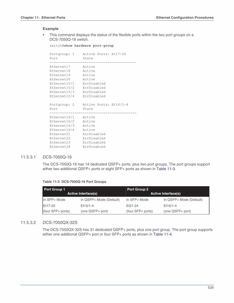
Example
• This command displays the status of the flexible ports within the two port groups on aDCS-7050Q-16 switch.
switch#show hardware port-group
Portgroup: 1 Active Ports: Et17-20Port State------------------------------------------Ethernet17 ActiveEthernet18 ActiveEthernet19 ActiveEthernet20 ActiveEthernet15/1 ErrDisabledEthernet15/2 ErrDisabledEthernet15/3 ErrDisabledEthernet15/4 ErrDisabled
Portgroup: 2 Active Ports: Et16/1-4Port State------------------------------------------Ethernet16/1 ActiveEthernet16/2 ActiveEthernet16/3 ActiveEthernet16/4 ActiveEthernet21 ErrDisabledEthernet22 ErrDisabledEthernet23 ErrDisabledEthernet24 ErrDisabled
11.5.3.1 DCS-7050Q-16
The DCS-7050Q-16 has 14 dedicated QSFP+ ports, plus two port groups. The port groups supporteither two additional QSFP+ ports or eight SFP+ ports as shown in Table 11-3.
11.5.3.2 DCS-7050QX-32S
The DCS-7050QX-32S has 31 dedicated QSFP+ ports, plus one port group. The port group supportseither one additional QSFP+ port or four SFP+ ports as shown in Table 11-4.
Table 11-3 DCS-7050Q-16 Port Groups
Port Group 1Active Interface(s)
Port Group 2Active Interface(s)
In SFP+ Mode In QSFP+ Mode (Default) In SFP+ Mode In QSFP+ Mode (Default)
Et17-20
(four SFP+ ports)
Et15/1-4
(one QSFP+ port)
Et21-24
(four SFP+ ports)
Et16/1-4
(one QSFP+ port)
540
Ethernet Configuration Procedures Chapter 11: Ethernet Ports
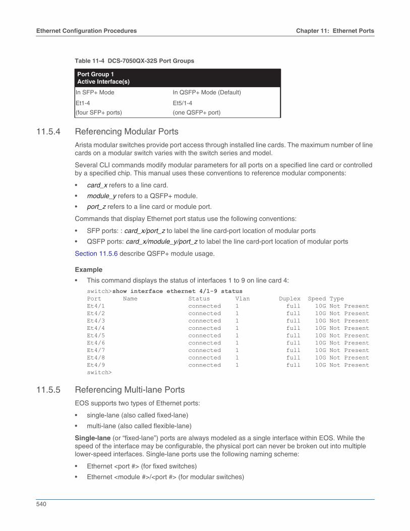
11.5.4 Referencing Modular Ports
Arista modular switches provide port access through installed line cards. The maximum number of linecards on a modular switch varies with the switch series and model.
Several CLI commands modify modular parameters for all ports on a specified line card or controlledby a specified chip. This manual uses these conventions to reference modular components:
• card_x refers to a line card.
• module_y refers to a QSFP+ module.
• port_z refers to a line card or module port.
Commands that display Ethernet port status use the following conventions:
• SFP ports: : card_x/port_z to label the line card-port location of modular ports
• QSFP ports: card_x/module_y/port_z to label the line card-port location of modular ports
Section 11.5.6 describe QSFP+ module usage.
Example
• This command displays the status of interfaces 1 to 9 on line card 4:
switch>show interface ethernet 4/1-9 statusPort Name Status Vlan Duplex Speed TypeEt4/1 connected 1 full 10G Not PresentEt4/2 connected 1 full 10G Not PresentEt4/3 connected 1 full 10G Not PresentEt4/4 connected 1 full 10G Not PresentEt4/5 connected 1 full 10G Not PresentEt4/6 connected 1 full 10G Not PresentEt4/7 connected 1 full 10G Not PresentEt4/8 connected 1 full 10G Not PresentEt4/9 connected 1 full 10G Not Presentswitch>
11.5.5 Referencing Multi-lane Ports
EOS supports two types of Ethernet ports:
• single-lane (also called fixed-lane)
• multi-lane (also called flexible-lane)
Single-lane (or “fixed-lane”) ports are always modeled as a single interface within EOS. While thespeed of the interface may be configurable, the physical port can never be broken out into multiplelower-speed interfaces. Single-lane ports use the following naming scheme:
• Ethernet <port #> (for fixed switches)
• Ethernet <module #>/<port #> (for modular switches)
Table 11-4 DCS-7050QX-32S Port Groups
Port Group 1Active Interface(s)
In SFP+ Mode In QSFP+ Mode (Default)
Et1-4
(four SFP+ ports)
Et5/1-4
(one QSFP+ port)

Chapter 11: Ethernet Ports Ethernet Configuration Procedures
541
Multi-lane (or “flexible lane”) ports are made up of multiple parallel lanes, each served by its own laser.Multi-lane ports can be configured to combine the lanes and operate as a single native high-speedinterface (a 40GbE or 100GbE interface), or to operate each lower-speed interface independently (four10GbE or 25GbE interfaces). Multi-lane ports use the following naming scheme:
• Ethernet <port #>/<lane #> (for fixed switches)
• Ethernet <module #>/<port #>/<lane #> (for modular switches)
The operational state displayed for each lane of a multi-lane port is determined by the configurationapplied to the primary lane(s), as shown in Table 11-5. When broken out into multiple lower-speedinterfaces, all lanes will be active in parallel, and each will display its operational state as connectedor not connected. In high-speed mode, only the primary lane(s) will be displayed as active, with theremaining lanes showing as errdisabled. The exception is the CFP2 module: when it is configured asa single 100GbE port, the primary lane is displayed as active in the CLI while the other lanes arehidden.
A multi-lane port is configured as a single high-speed interface or multiple breakout interfaces by usingthe speed command on the primary lane(s) of the port. For specific configuration instructions anddetails regarding the primary lane(s) of a specific interface, refer to the configuration section for theappropriate interface type:
• QSFP+ Ethernet Port Configuration
• QSFP100 Ethernet Port Configuration
• CFP2 Ethernet Port Configuration
• MXP Ethernet Port Configuration
Important! Use of the speed command to configure a multi-lane port is hitless on the 7050X, 7060X, 7250X,7260X, 7280SE, 7300X, 7320X and 7500E series platforms. On all other platforms, this commandrestarts the forwarding agent, which will result in traffic disruption. On 7160 series platforms, use of thespeed command is hitless, but if the command changes the number of port lanes, packets may bedropped on unrelated ports.
11.5.6 QSFP+ Ethernet Port Configuration
Each QSFP+ module contains four data lanes which can be used individually or combined to form asingle, higher-speed interface. This allows a QSFP+ Ethernet port to be configured as a single 40GbEinterface or as four 10GbE interfaces.
When the four lanes are combined to form a 40GbE interface, display commands will show lane /1 asconnected or not connected, and will show lanes /2 through /4 as errdisabled.
The following sections describe the configuration of QSFP+ ports.
Table 11-5 Lane States
Parent PortConfigured Mode
Primary Lane(s) Secondary Lanes
single high-speed
interface
active
(connected/not connected)
inactive
(errdisabled)
multi-interface
breakout
active
(connected/not connected)
active
(connected/not connected)

542
Ethernet Configuration Procedures Chapter 11: Ethernet Ports
11.5.6.1 Configuring a QSFP+ Module as a Single 40GbE Interface
To configure the port as a single 40GbE interface, combine the module’s four data lanes by using thespeed command (speed forced 40g full) on the port’s /1 lane (the primary lane).
Important! Use of the speed command to configure a multi-lane port is hitless on the 7050X, 7060X, 7250X,7260X, 7280SE, 7300X, 7320X and 7500E series platforms. On all other platforms, this commandrestarts the forwarding agent, which will result in traffic disruption. On 7160 series platforms, use of thespeed command is hitless, but if the command changes the number of port lanes, packets may bedropped on unrelated ports.
Step 1 Enter interface Ethernet configuration mode for lane /1 of the QSFP+ Ethernet interface.
switch(config)#interface ethernet 5/1/1Step 2 Enter the speed forced 40gfull command. Depending on the platform, this command may
restart the forwarding agent, disrupting traffic on all ports for 60 seconds or more.
switch(config-if-Et5/1/1)#speed forced 40gfullStep 3 Use the show interfaces status command to confirm the change in configuration.
switch(config-if-Et5/1/1)#show interfaces statusPort Name Status Vlan Duplex Speed Type FlagsEt1 connected 2 full 1G 10GBASE-T
<-------OUTPUT OMITTED FROM EXAMPLE-------->Et5/1/1 connected 1 full 40G 40GBASE-SR4Et5/1/2 errdisabled 1 unconf unconf 40GBASE-SR4Et5/1/3 errdisabled 1 unconf unconf 40GBASE-SR4Et5/1/4 errdisabled 1 unconf unconf 40GBASE-SR4
<-------OUTPUT OMITTED FROM EXAMPLE-------->
11.5.6.2 Configuring a QSFP+ Module as Four 10GbE Interfaces
To configure the port as four 10GbE interfaces, use the speed command (speed forced 10000full) onthe port’s /1 lane (the primary lane).
Important! Use of the speed command to configure a multi-lane port is hitless on the 7050X, 7060X, 7250X,7260X, 7280SE, 7300X, 7320X and 7500E series platforms. On all other platforms, this commandrestarts the forwarding agent, which will result in traffic disruption. On 7160 series platforms, use of thespeed command is hitless, but if the command changes the number of port lanes, packets may bedropped on unrelated ports.
Step 1 Enter interface Ethernet configuration mode for lane /1 of the QSFP+ Ethernet interface.
switch(config)#interface ethernet 5/1/1Step 2 Enter the speed forced 10000full command. Depending on the platform, this command may
restart the forwarding agent, disrupting traffic on all ports for 60 seconds or more.
switch(config-if-Et5/1/1)#speed forced 10000full

Chapter 11: Ethernet Ports Ethernet Configuration Procedures
543
Step 3 Use the show interfaces status command to confirm the change in configuration.
switch(config-if-Et5/1/1)#show interfaces statusPort Name Status Vlan Duplex Speed Type FlagsEt1 connected 2 full 1G 10GBASE-T
<-------OUTPUT OMITTED FROM EXAMPLE-------->Et5/1/1 connected 1 full 10G 40GBASE-SR4Et5/1/2 connected 1 full 10G 40GBASE-SR4Et5/1/3 connected 1 full 10G 40GBASE-SR4Et5/1/4 connected 1 full 10G 40GBASE-SR4
<-------OUTPUT OMITTED FROM EXAMPLE-------->
11.5.7 QSFP100 Ethernet Port Configuration
Each QSFP100 module contains four data lanes which can be used individually or combined to forma single, higher-speed interface. This allows a QSFP100 Ethernet port to be configured as a single100GbE interface, a single 40GbE interface, or four 10GbE interfaces. The default mode is a single100GbE interface.
The 7060X, 7260X and 7320X platforms also allow a QSFP100 port to be configured as two 50GbEinterfaces or four 25GbE interfaces.
When the lanes are combined to form a higher-speed interface, display commands will show theprimary lane(s) as connected or not connected, and will show the other lanes as errdisabled.
The following sections describe the configuration of QSFP+ ports.
11.5.7.1 Configuring a QSFP100 Module as a Single 100GbE Interface
By default, the QSFP100 module operates as a single 100GbE interface; using the default speed orno speed command on the primary lane restores the default behavior.
To explicitly configure the port as a single 100GbE interface, combine the module’s four data lanes byusing the speed command (speed forced 100gfull) on the port’s /1 lane (the primary lane).
Important! Use of the speed command to configure a multi-lane port is hitless on the 7050X, 7060X, 7250X,7260X, 7280SE, 7300X, 7320X and 7500E series platforms. On all other platforms, this commandrestarts the forwarding agent, which will result in traffic disruption. On 7160 series platforms, use of thespeed command is hitless, but if the command changes the number of port lanes, packets may bedropped on unrelated ports.
Step 1 Enter interface Ethernet configuration mode for lane /1 of the QSFP100 Ethernet interface.
switch(config)#interface ethernet 5/1/1Step 2 Enter the speed forced 100gfull command. Depending on the platform, this command may
restart the forwarding agent, disrupting traffic on all ports for 60 seconds or more.
switch(config-if-Et5/1/1)#speed forced 100gfullStep 3 Use the show interfaces status command to confirm the change in configuration.
switch(config-if-Et5/1/1)#show interfaces statusPort Name Status Vlan Duplex Speed Type FlagsEt1 connected 2 full 1G 10GBASE-T
<-------OUTPUT OMITTED FROM EXAMPLE-------->Et5/1/1 connected 1 full 100G 100GBASE-SR4Et5/1/2 errdisabled 1 unconf unconf 100GBASE-SR4Et5/1/3 errdisabled 1 unconf unconf 100GBASE-SR4Et5/1/4 errdisabled 1 unconf unconf 100GBASE-SR4
<-------OUTPUT OMITTED FROM EXAMPLE-------->

544
Ethernet Configuration Procedures Chapter 11: Ethernet Ports
11.5.7.2 Configuring a QSFP100 Module as Two 50GbE Interfaces
To configure the port as a two 50GbE interfaces, configure the module’s four data lanes by using thespeed command (speed forced 50gfull) on the port’s /1 and /3 lanes. This configuration is availableon 7060X, 7260X and 7320X platforms.
Important! Use of the speed command to configure a multi-lane port is hitless on the 7050X, 7060X, 7250X,7260X, 7280SE, 7300X, 7320X and 7500E series platforms. On all other platforms, this commandrestarts the forwarding agent, which will result in traffic disruption. On 7160 series platforms, use of thespeed command is hitless, but if the command changes the number of port lanes, packets may bedropped on unrelated ports.
Step 1 Enter interface Ethernet configuration mode for lane /1 of the QSFP100 Ethernet interface.
switch(config)#interface ethernet 5/1/1Step 2 Enter the speed forced 50gfull command. Depending on the platform, this command may
restart the forwarding agent, disrupting traffic on all ports for 60 seconds or more.
switch(config-if-Et5/1/1)#speed forced 50gfullStep 3 Repeat the above steps for lane /3.
switch(config-if-Et5/1/1)#interface ethernet 5/1/3switch(config-if-Et5/1/3)#speed forced 50gfull
Step 4 Use the show interfaces status command to confirm the change in configuration.
switch(config-if-Et5/1/1)#show interfaces statusPort Name Status Vlan Duplex Speed Type FlagsEt1 connected 2 full 1G 10GBASE-T
<-------OUTPUT OMITTED FROM EXAMPLE-------->Et5/1/1 connected 1 full 50G 100GBASE-SR4Et5/1/2 errdisabled 1 unconf unconf 100GBASE-SR4Et5/1/3 connected 1 full 50G 100GBASE-SR4Et5/1/4 errdisabled 1 unconf unconf 100GBASE-SR4
<-------OUTPUT OMITTED FROM EXAMPLE-------->
11.5.7.3 Configuring a QSFP100 Module as a Single 40GbE Interface
To configure the port as a single 40GbE interface, combine the module’s four data lanes by using thespeed command (speed forced 40gfull) on the port’s /1 lane (the primary lane).
Important! Use of the speed command to configure a multi-lane port is hitless on the 7050X, 7060X, 7250X,7260X, 7280SE, 7300X, 7320X and 7500E series platforms. On all other platforms, this commandrestarts the forwarding agent, which will result in traffic disruption. On 7160 series platforms, use of thespeed command is hitless, but if the command changes the number of port lanes, packets may bedropped on unrelated ports.
Step 1 Enter interface Ethernet configuration mode for lane /1 of the QSFP100 Ethernet interface.
switch(config)#interface ethernet 5/1/1Step 2 Enter the speed forced 40gfull command. Depending on the platform, this command may
restart the forwarding agent, disrupting traffic on all ports for 60 seconds or more.
switch(config-if-Et5/1/1)#speed forced 40gfull

Chapter 11: Ethernet Ports Ethernet Configuration Procedures
545
Step 3 Use the show interfaces status command to confirm the change in configuration.
switch(config-if-Et5/1/1)#show interfaces statusPort Name Status Vlan Duplex Speed Type FlagsEt1 connected 2 full 1G 10GBASE-T
<-------OUTPUT OMITTED FROM EXAMPLE-------->Et5/1/1 connected 1 full 40G 100GBASE-SR4Et5/1/2 errdisabled 1 unconf unconf 100GBASE-SR4Et5/1/3 errdisabled 1 unconf unconf 100GBASE-SR4Et5/1/4 errdisabled 1 unconf unconf 100GBASE-SR4
<-------OUTPUT OMITTED FROM EXAMPLE-------->
11.5.7.4 Configuring a QSFP100 Module as Four 25GbE Interfaces
To configure the port as four 25GbE interfaces, use the speed command (speed forced 25gfull) onthe port’s /1 lane (the primary lane). This configuration is available on 7060X, 7260X and 7320Xplatforms.
Important! Use of the speed command to configure a multi-lane port is hitless on the 7050X, 7060X, 7250X,7260X, 7280SE, 7300X, 7320X and 7500E series platforms. On all other platforms, this commandrestarts the forwarding agent, which will result in traffic disruption. On 7160 series platforms, use of thespeed command is hitless, but if the command changes the number of port lanes, packets may bedropped on unrelated ports.
Step 1 Enter interface Ethernet configuration mode for lane /1 of the QSFP100 Ethernet interface.
switch(config)#interface ethernet 5/1/1Step 2 Enter the speed forced 25gfull command. Depending on the platform, this command may
restart the forwarding agent, disrupting traffic on all ports for 60 seconds or more.
switch(config-if-Et5/1/1)#speed forced 25gfullStep 3 Use the show interfaces status command to confirm the change in configuration.
switch(config-if-Et5/1/1)#show interfaces statusPort Name Status Vlan Duplex Speed Type FlagsEt1 connected 2 full 1G 10GBASE-T
<-------OUTPUT OMITTED FROM EXAMPLE-------->Et5/1/1 connected 1 full 25G 100GBASE-SR4Et5/1/2 errdisabled 1 unconf unconf 100GBASE-SR4Et5/1/3 errdisabled 1 unconf unconf 100GBASE-SR4Et5/1/4 errdisabled 1 unconf unconf 100GBASE-SR4
<-------OUTPUT OMITTED FROM EXAMPLE-------->
11.5.7.5 Configuring a QSFP100 Module as Four 10GbE Interfaces
To configure the port as four 10GbE interfaces, use the speed command (speed forced 10000full) onthe port’s /1 lane (the primary lane).
Important! Use of the speed command to configure a multi-lane port is hitless on the 7050X, 7060X, 7250X,7260X, 7280SE, 7300X, 7320X and 7500E series platforms. On all other platforms, this commandrestarts the forwarding agent, which will result in traffic disruption. On 7160 series platforms, use of thespeed command is hitless, but if the command changes the number of port lanes, packets may bedropped on unrelated ports.
Step 1 Enter interface Ethernet configuration mode for lane /1 of the QSFP100 Ethernet interface.
switch(config)#interface ethernet 5/1/1
546
Ethernet Configuration Procedures Chapter 11: Ethernet Ports
Step 2 Enter the speed forced 10000full command. Depending on the platform, this command mayrestart the forwarding agent, disrupting traffic on all ports for 60 seconds or more.
switch(config-if-Et5/1/1)#speed forced 10000fullStep 3 Use the show interfaces status command to confirm the change in configuration.
switch(config-if-Et5/1/1)#show interfaces statusPort Name Status Vlan Duplex Speed Type FlagsEt1 connected 2 full 1G 10GBASE-T
<-------OUTPUT OMITTED FROM EXAMPLE-------->Et5/1/1 connected 1 full 10G 100GBASE-SR4Et5/1/2 connected 1 full 10G 100GBASE-SR4Et5/1/3 connected 1 full 10G 100GBASE-SR4Et5/1/4 connected 1 full 10G 100GBASE-SR4
<-------OUTPUT OMITTED FROM EXAMPLE-------->
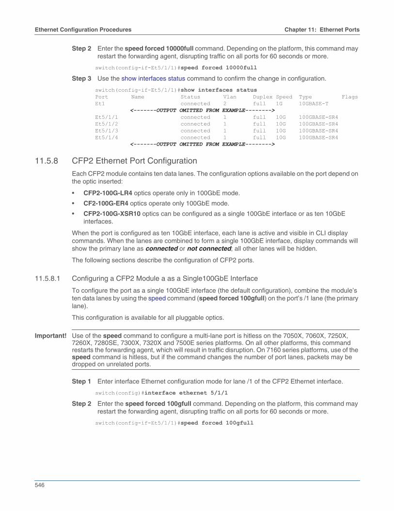
11.5.8 CFP2 Ethernet Port Configuration
Each CFP2 module contains ten data lanes. The configuration options available on the port depend onthe optic inserted:
• CFP2-100G-LR4 optics operate only in 100GbE mode.
• CF2-100G-ER4 optics operate only 100GbE mode.
• CFP2-100G-XSR10 optics can be configured as a single 100GbE interface or as ten 10GbEinterfaces.
When the port is configured as ten 10GbE interface, each lane is active and visible in CLI displaycommands. When the lanes are combined to form a single 100GbE interface, display commands willshow the primary lane as connected or not connected; all other lanes will be hidden.
The following sections describe the configuration of CFP2 ports.
11.5.8.1 Configuring a CFP2 Module a as a Single100GbE Interface
To configure the port as a single 100GbE interface (the default configuration), combine the module’sten data lanes by using the speed command (speed forced 100gfull) on the port’s /1 lane (the primarylane).
This configuration is available for all pluggable optics.
Important! Use of the speed command to configure a multi-lane port is hitless on the 7050X, 7060X, 7250X,7260X, 7280SE, 7300X, 7320X and 7500E series platforms. On all other platforms, this commandrestarts the forwarding agent, which will result in traffic disruption. On 7160 series platforms, use of thespeed command is hitless, but if the command changes the number of port lanes, packets may bedropped on unrelated ports.
Step 1 Enter interface Ethernet configuration mode for lane /1 of the CFP2 Ethernet interface.
switch(config)#interface ethernet 5/1/1Step 2 Enter the speed forced 100gfull command. Depending on the platform, this command may
restart the forwarding agent, disrupting traffic on all ports for 60 seconds or more.
switch(config-if-Et5/1/1)#speed forced 100gfull

Chapter 11: Ethernet Ports Ethernet Configuration Procedures
547
Step 3 Use the show interfaces status command to confirm the change in configuration.
switch(config-if-Et5/1/1)#show interfaces statusPort Name Status Vlan Duplex Speed Type FlagsEt1 connected 2 full 1G 10GBASE-T
<-------OUTPUT OMITTED FROM EXAMPLE-------->Et5/1/1 connected 1 full 100G 100GBASE-SR1Et5/2/1 connected 1 full 100G 100GBASE-SR1
<-------OUTPUT OMITTED FROM EXAMPLE-------->
11.5.8.2 Configuring a CFP2 Module as Ten 10GbE Interfaces
To configure the port as four 10GbE interfaces, use the speed command (speed forced 10000full) onthe port’s /1 lane (the primary lane).
This configuration is available only for CFP2-100G-XSR10 optics.
Important! Use of the speed command to configure a multi-lane port is hitless on the 7050X, 7060X, 7250X,7260X, 7280SE, 7300X, 7320X and 7500E series platforms. On all other platforms, this commandrestarts the forwarding agent, which will result in traffic disruption. On 7160 series platforms, use of thespeed command is hitless, but if the command changes the number of port lanes, packets may bedropped on unrelated ports.
Step 1 Enter interface Ethernet configuration mode for lane /1 of the CFP2 Ethernet interface.
switch(config)#interface ethernet 5/1/1Step 2 Enter the speed forced 10000full command. Depending on the platform, this command may
restart the forwarding agent, disrupting traffic on all ports for 60 seconds or more.
switch(config-if-Et5/1/1)#speed forced 10000fullStep 3 Use the show interfaces status command to confirm the change in configuration.
switch(config-if-Et5/1/1)#show interfaces statusPort Name Status Vlan Duplex Speed Type FlagsEt1 connected 2 full 1G 10GBASE-T
<-------OUTPUT OMITTED FROM EXAMPLE-------->Et5/1/1 connected 1 full 10G 100GBASE-SR1Et5/1/2 connected 1 full 10G 100GBASE-SR1Et5/1/3 connected 1 full 10G 100GBASE-SR1Et5/1/4 connected 1 full 10G 100GBASE-SR1Et5/1/5 connected 1 full 10G 100GBASE-SR1Et5/1/6 connected 1 full 10G 100GBASE-SR1Et5/1/7 connected 1 full 10G 100GBASE-SR1Et5/1/8 connected 1 full 10G 100GBASE-SR1Et5/1/9 connected 1 full 10G 100GBASE-SR1Et5/1/10 connected 1 full 10G 100GBASE-SR1
<-------OUTPUT OMITTED FROM EXAMPLE-------->
11.5.9 MXP Ethernet Port Configuration
Each MXP module contains twelve data lanes which can be used individually or combined to form oneor more higher-speed interfaces. This allows an MXP Ethernet port to be configured as a single100GbE interface, up to twelve 10GbE interfaces, or a mixture of 40GbE and 10GbE ports.
MXP ports do not use pluggable optics: instead, an MTP-24 ribbon is inserted directly into the port.The remote end of the MTP 24 ribbon must then be broken out using a splitter cable or cartridge basedon the operational mode and speed of the MXP port.

548
Ethernet Configuration Procedures Chapter 11: Ethernet Ports
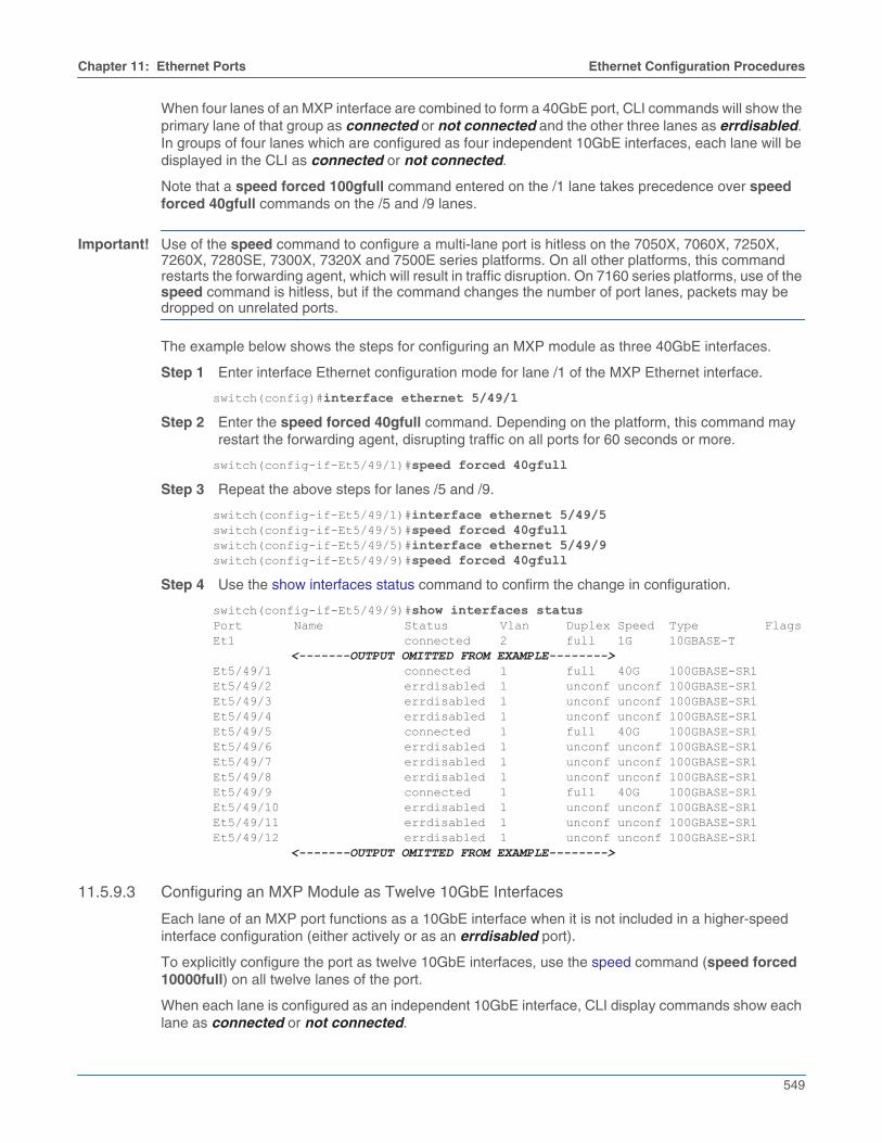
When four lanes of an MXP interface are combined to form a 40GbE port, CLI commands will show theprimary lane of that group as connected or not connected and the other three lanes as errdisabled.
The following sections describe the configuration of MXP interfaces.
11.5.9.1 Configuring an MXP Module as a Single 100GbE Interface
To configure the port as a single 100GbE interface (the default configuration), enter the speedcommand (speed forced 100gfull) on the port’s /1 lane (the primary lane). This combines lanes 1-10and disables lanes 11 and 12.
Under this configuration, CLI display commands will show lane /1 as connected or not connected,and show lanes /2-/12 as errdisabled.
Important! Use of the speed command to configure a multi-lane port is hitless on the 7050X, 7060X, 7250X,7260X, 7280SE, 7300X, 7320X and 7500E series platforms. On all other platforms, this commandrestarts the forwarding agent, which will result in traffic disruption. On 7160 series platforms, use of thespeed command is hitless, but if the command changes the number of port lanes, packets may bedropped on unrelated ports.
Step 1 Enter interface Ethernet configuration mode for lane /1 of the MXP Ethernet interface.
switch(config)#interface ethernet 5/49/1Step 2 Enter the speed forced 100gfull command. Depending on the platform, this command may
restart the forwarding agent, disrupting traffic on all ports for 60 seconds or more.
switch(config-if-Et5/49/1)#speed forced 100gfullStep 3 Use the show interfaces status command to confirm the change in configuration.
switch(config-if-Et5/49/1)#show interfaces statusPort Name Status Vlan Duplex Speed Type FlagsEt1 connected 2 full 1G 10GBASE-T
<-------OUTPUT OMITTED FROM EXAMPLE-------->Et5/49/1 connected 1 full 100G 100GBASE-SR1Et5/49/2 errdisabled 1 unconf unconf 100GBASE-SR1Et5/49/3 errdisabled 1 unconf unconf 100GBASE-SR1Et5/49/4 errdisabled 1 unconf unconf 100GBASE-SR1Et5/49/5 errdisabled 1 unconf unconf 100GBASE-SR1Et5/49/6 errdisabled 1 unconf unconf 100GBASE-SR1Et5/49/7 errdisabled 1 unconf unconf 100GBASE-SR1Et5/49/8 errdisabled 1 unconf unconf 100GBASE-SR1Et5/49/9 errdisabled 1 unconf unconf 100GBASE-SR1Et5/49/10 errdisabled 1 unconf unconf 100GBASE-SR1Et5/49/11 errdisabled 1 unconf unconf 100GBASE-SR1Et5/49/12 errdisabled 1 unconf unconf 100GBASE-SR1
<-------OUTPUT OMITTED FROM EXAMPLE-------->
11.5.9.2 Configuring an MXP Module With 40GbE Interfaces
Each set of four lanes on the MXP module is independently configurable as a single 40GbE interfaceor four 10GbE interfaces. To configure four lanes as a single 40GbE interface, enter the speedcommand (speed forced 40gfull) on the group’s primary lane (/1, /5, or /9). To revert a group of fourlanes to functioning as four independent 10GbE interfaces, enter the speed forced 10000fullcommand on the primary lane of the group.
Chapter 11: Ethernet Ports Ethernet Configuration Procedures
549
When four lanes of an MXP interface are combined to form a 40GbE port, CLI commands will show theprimary lane of that group as connected or not connected and the other three lanes as errdisabled.In groups of four lanes which are configured as four independent 10GbE interfaces, each lane will bedisplayed in the CLI as connected or not connected.
Note that a speed forced 100gfull command entered on the /1 lane takes precedence over speedforced 40gfull commands on the /5 and /9 lanes.
Important! Use of the speed command to configure a multi-lane port is hitless on the 7050X, 7060X, 7250X,7260X, 7280SE, 7300X, 7320X and 7500E series platforms. On all other platforms, this commandrestarts the forwarding agent, which will result in traffic disruption. On 7160 series platforms, use of thespeed command is hitless, but if the command changes the number of port lanes, packets may bedropped on unrelated ports.
The example below shows the steps for configuring an MXP module as three 40GbE interfaces.
Step 1 Enter interface Ethernet configuration mode for lane /1 of the MXP Ethernet interface.
switch(config)#interface ethernet 5/49/1Step 2 Enter the speed forced 40gfull command. Depending on the platform, this command may
restart the forwarding agent, disrupting traffic on all ports for 60 seconds or more.
switch(config-if-Et5/49/1)#speed forced 40gfullStep 3 Repeat the above steps for lanes /5 and /9.
switch(config-if-Et5/49/1)#interface ethernet 5/49/5switch(config-if-Et5/49/5)#speed forced 40gfullswitch(config-if-Et5/49/5)#interface ethernet 5/49/9switch(config-if-Et5/49/9)#speed forced 40gfull
Step 4 Use the show interfaces status command to confirm the change in configuration.
switch(config-if-Et5/49/9)#show interfaces statusPort Name Status Vlan Duplex Speed Type FlagsEt1 connected 2 full 1G 10GBASE-T
<-------OUTPUT OMITTED FROM EXAMPLE-------->Et5/49/1 connected 1 full 40G 100GBASE-SR1Et5/49/2 errdisabled 1 unconf unconf 100GBASE-SR1Et5/49/3 errdisabled 1 unconf unconf 100GBASE-SR1Et5/49/4 errdisabled 1 unconf unconf 100GBASE-SR1Et5/49/5 connected 1 full 40G 100GBASE-SR1Et5/49/6 errdisabled 1 unconf unconf 100GBASE-SR1Et5/49/7 errdisabled 1 unconf unconf 100GBASE-SR1Et5/49/8 errdisabled 1 unconf unconf 100GBASE-SR1Et5/49/9 connected 1 full 40G 100GBASE-SR1Et5/49/10 errdisabled 1 unconf unconf 100GBASE-SR1Et5/49/11 errdisabled 1 unconf unconf 100GBASE-SR1Et5/49/12 errdisabled 1 unconf unconf 100GBASE-SR1
<-------OUTPUT OMITTED FROM EXAMPLE-------->
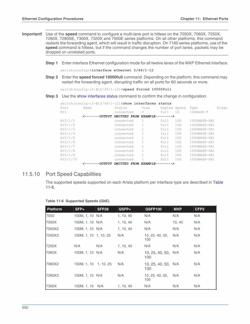
11.5.9.3 Configuring an MXP Module as Twelve 10GbE Interfaces
Each lane of an MXP port functions as a 10GbE interface when it is not included in a higher-speedinterface configuration (either actively or as an errdisabled port).
To explicitly configure the port as twelve 10GbE interfaces, use the speed command (speed forced10000full) on all twelve lanes of the port.
When each lane is configured as an independent 10GbE interface, CLI display commands show eachlane as connected or not connected.
550
Ethernet Configuration Procedures Chapter 11: Ethernet Ports
Important! Use of the speed command to configure a multi-lane port is hitless on the 7050X, 7060X, 7250X,7260X, 7280SE, 7300X, 7320X and 7500E series platforms. On all other platforms, this commandrestarts the forwarding agent, which will result in traffic disruption. On 7160 series platforms, use of thespeed command is hitless, but if the command changes the number of port lanes, packets may bedropped on unrelated ports.
Step 1 Enter interface Ethernet configuration mode for all twelve lanes of the MXP Ethernet interface.
switch(config)#interface ethernet 5/49/1-12Step 2 Enter the speed forced 10000full command. Depending on the platform, this command may
restart the forwarding agent, disrupting traffic on all ports for 60 seconds or more.
switch(config-if-Et5/49/1-12)#speed forced 10000fullStep 3 Use the show interfaces status command to confirm the change in configuration.
switch(config-if-Et5/49/1-12)#show interfaces statusPort Name Status Vlan Duplex Speed Type FlagsEt1 connected 2 full 1G 10GBASE-T
<-------OUTPUT OMITTED FROM EXAMPLE-------->Et5/1/1 connected 1 full 10G 100GBASE-SR1Et5/1/2 connected 1 full 10G 100GBASE-SR1Et5/1/3 connected 1 full 10G 100GBASE-SR1Et5/1/4 connected 1 full 10G 100GBASE-SR1Et5/1/5 connected 1 full 10G 100GBASE-SR1Et5/1/6 connected 1 full 10G 100GBASE-SR1Et5/1/7 connected 1 full 10G 100GBASE-SR1Et5/1/8 connected 1 full 10G 100GBASE-SR1Et5/1/9 connected 1 full 10G 100GBASE-SR1Et5/1/10 connected 1 full 10G 100GBASE-SR1
<-------OUTPUT OMITTED FROM EXAMPLE-------->
11.5.10 Port Speed Capabilities
The supported speeds supported on each Arista platform per interface type are described in Table11-6.
Table 11-6 Supported Speeds (GbE)
Platform SFP+ SFP28 QSFP+ QSFP100 MXP CFP2
7050 100M, 1, 10 N/A 1, 10, 40 N/A N/A N/A
7050X 100M, 1, 10 N/A 1, 10, 40 N/A 10, 40 N/A
7050X2 100M, 1, 10 N/A 1, 10, 40 N/A N/A N/A
7050X3 100M, 1, 10 1, 10, 25 N/A 10, 25, 40, 50,100
N/A N/A
7250X N/A N/A 1, 10, 40 N/A N/A N/A
7060X 100M, 1, 10 N/A N/A 10, 25, 40, 50,100
N/A N/A
7060X2 100M, 1, 10 1, 10, 25 N/A 10, 25, 40, 50,100
N/A N/A
7260X3 100M, 1, 10 N/A N/A 10, 25, 40, 50,100
N/A N/A
7300X 100M, 1, 10 N/A 1, 10, 40 N/A N/A N/A

Chapter 11: Ethernet Ports Ethernet Configuration Procedures
551
11.5.11 Agile Ports
An agile port is an interface that can function as a 10G port or can subsume a predefined set of 10Ginterfaces to form an interface with higher speed capabilities.
The set of interfaces that can be combined to form a higher speed port is restricted by the hardwareconfiguration. Only interfaces that pass through a common PHY component can be combined. Oneinterface within a combinable set is designated as the primary port.
• To view the set of available agile ports and the subsumable interfaces that comprise them, entershow platform fm6000 agileport map.
• To configure the primary port as a higher speed port, enter speed forced 40gfull or speed auto40gfull.
• To revert the primary port and its subsumed ports to 10G interfaces, enter no speed.
7300X3 N/A 1, 10, 25 N/A 10, 25, 40, 50,100
N/A N/A
7320X N/A N/A N/A 10, 25, 40, 50,100
N/A N/A
7150S 1, 10 N/A 1, 10, 40 N/A N/A N/A
7048T 1, 10 N/A N/A N/A N/A N/A
7500 1, 10 N/A 1, 10, 40 N/A N/A N/A
7500E 1, 10 N/A 1, 10, 40 10, 40, 100 10, 40, 100 100
7500R 1, 10 1, 10, 25 1, 10, 40 10, 25, 40, 50,100
N/A N/A
7280SE 1, 10 N/A 1, 10, 40 10, 40, 100 10, 40, 100 N/A
7280QR N/A N/A 1, 10, 40 10, 25, 40, 50,100
N/A N/A
7280SR (R2) 1, 10 1, 10, 25 N/A 10, 25, 40, 50,100
N/A 100, 200
7280CR N/A N/A N/A 10, 25, 40, 50,100
N/A N/A
7010T 100M, 1, 10 N/A N/A N/A N/A N/A
Table 11-6 Supported Speeds (GbE)
Platform SFP+ SFP28 QSFP+ QSFP100 MXP CFP2

552
Ethernet Configuration Procedures Chapter 11: Ethernet Ports
Example
• These commands displays the agile port map for the switch, then configures ethernet interface 13as a 40G port.
switch#show platform fm6000 agileport map
-----------------------------------------------------------------Agile Ports | Interfaces subsumed in 40G link-----------------------------------------------------------------Ethernet1 | Ethernet3 Ethernet5 Ethernet7Ethernet2 | Ethernet4 Ethernet6 Ethernet8Ethernet13 | Ethernet15 Ethernet17 Ethernet19Ethernet14 | Ethernet16 Ethernet18 Ethernet20switch#configswitch(config)#interface ethernet 13switch(config-if-Et13)#speed forced 40gfull
WARNING! Executing this command will cause the forwarding agent to be restarted. All interfaces will briefly drop links and forwarding on all interfaces will momentarily stop.
Do you wish to proceed with this command? [y/N]
Ethernet17 configured for 40G.Ethernet15, Ethernet17 and Ethernet19 are now subsumed.switch(config-if-Et13)#This command reverts the agile 40G port to a 10G port and frees its subsumed ports as individual 10G ports.switch(config-if-Et13)#no speed
WARNING! Executing this command will cause the forwarding agent to be restarted. All interfaces will briefly drop links and forwarding on all interfaces will momentarily stop.
Do you wish to proceed with this command? [y/N]
Ethernet13 no longer configured for 40G.Ethernet15, Ethernet17 and Ethernet19 are now free.switch(config-if-Et13)#
11.5.12 Subinterface Configuration
For a subinterface to be operational on an Ethernet or port channel interface, the parent interface mustbe configured as a routed port and be administratively up, and a VLAN must be configured on thesubinterface. If the parent interface goes down, all subinterfaces automatically go down as well, but willcome back up with the same configuration once the parent interface is up.
Note that a port channel should not contain Ethernet interfaces with subinterfaces configured on them,and that subinterfaces cannot be members of a port channel.
Subinterfaces are named by adding a period followed by a unique subinterface number to the name ofthe parent interface. Note that the subinterface number has no relation to the ID of the VLANcorresponding to the subinterface.
Subinterfaces are available on the following platforms:
• DCS-7050X

Chapter 11: Ethernet Ports Ethernet Configuration Procedures
553
• DCS-7060X
• DCS-7250X
• DCS-7260X
• DCS-7280E
• DCS-7300X
• DCS-7320X
• DCS-7500E
11.5.12.1 Creating a Subinterface
To create a subinterface on an Ethernet or port channel interface:
Step 1 Bring up the parent interface and ensure that it is configured as a routed port.
switch(config)#interface Ethernet1/1switch(config-if-Et1/1)#no switchportswitch(config-if-Et1/1)#no shutdown
Step 2 Configure a VLAN on the subinterface. The encapsulation dot1q vlan command is also usedfor VLAN translation, but in this context it associates a VLAN with the subinterface.
switch(config-if-Et1/1)#interface Ethernet1/1.1switch(config-if-Et1/1.1)#encapsulation dot1q vlan 100
Step 3 Configure an IP address on the subinterface (optional) and ensure that it is up.
switch(config-if-Et1/1)#ip address 10.0.0.1/24switch(config-if-Et1/1)#no shutdownswitch(config-if-Et1/1)#
11.5.12.2 Creating a Range of Subinterfaces
A range of subinterfaces can also be configured simultaneously. The following example configuressubinterfaces 1 to 100 on Ethernet interface 1/1, and assigns VLANs 501 through 600 to them. Notethat the range of interfaces must be the same size as the range of VLAN IDs.
Example
switch(config)#interface eth1/1.1-100switch(config-if-Et1/1.1-100)no shutdownswitch(config-if-Et1/1.1-100)encapsulation dot1q vlan {501,600}switch(config-if-Et1/1.1-100)exitswitch(config)#
11.5.12.3 Parent Interface Configuration
For subinterfaces to function, the parent interface must be administratively up and configured as arouted port.
Some settings are inherited by subinterfaces from the parent interface. These include QoS (trust modeand default DSCP) and MTU.
Additionally, on the DCS-7050X, DCS-7250X, and DCS-7300X platforms, the parent interface may beconfigured with an IP address. In this case, untagged packets are treated as incoming traffic on theparent interface

554
Ethernet Configuration Procedures Chapter 11: Ethernet Ports
11.5.12.4 Configuring Routing Features on a Subinterface
Once a subinterface is created, the following features can be configured on it:
• Unicast and multicast routing
• BGP, OSPF, ISIS, PIM
• VRF
• VRRP
• SNMP
• Inheritance of QoS (trust mode and default DSCP) and MTU settings from the parent interface
Additionally, these features can be configured on subinterfaces on Arad (DCS-7500E and DCS-7280E)platforms:
• Subinterface counters on ingress
• VXLAN
• MPLS
• GRE
• PBR
• QoS
11.5.12.5 Displaying Subinterface Information
Subinterface information is displayed using the same show commands as for other interfaces.
Examples
This command displays summary information for all IP interfaces on the switch, includingsubinterfaces.
switch>show ip interfaces brief Interface IP Address Status Protocol MTU Ethernet1/1 10.1.1.1/24 up up 1500 Ethernet1/1.1 10.0.0.1/24 up up 1500 Ethernet1/2 unassigned up up 1500
This command displays information for subinterface Ethernet 1/1.1.
switch>show interface ethernet 1/1.1Ethernet1/1.1 is down, line protocol is lowerlayerdown (notconnect) Hardware is Subinterface, address is 001c.735d.65dc Internet address is 10.0.0.1/24 Broadcast address is 255.255.255.255 Address determined by manual configuration IP MTU 1500 bytes , BW 10000000 kbit Down 59 secondsswitch>
This command displays status information for all subinterfaces configured on the switch.
switch>show interfaces status sub-interfacesPort Name Status Vlan Duplex Speed Type FlagsEt1.1 connect 101 full 10G dot1q-encapsulationEt1.2 connect 102 full 10G dot1q-encapsulationEt1.3 connect 103 full 10G dot1q-encapsulationEt1.4 connect 103 full 10G dot1q-encapsulationswitch>

Chapter 11: Ethernet Ports Ethernet Configuration Procedures
555
11.5.13 Autonegotiated Settings
In autonegotiation, the transmission speed, duplex setting, and flow control parameters used forEthernet-based communication can be automatically negotiated between connected devices toestablish optimized common settings.
11.5.13.1 Speed and Duplex
The speed command affects the transmission speed and duplex setting for the configuration modeinterface. When a speed forced command is in effect on an interface, autonegotiation of speed andduplex settings is disabled for the interface; to enable autonegotiation, use the speed auto command.
The scope and effect of the speed command depends on the interface type; see Ethernet Interfacesand Ethernet Configuration Procedures for detailed information on the speed settings for differentinterfaces.
11.5.13.2 Flow Control
Flow control is a data transmission option that temporarily stops a device from sending data becauseof a peer data overflow condition. If a device sends data faster than the receiver can accept it, thereceiver's buffer can overflow. The receiving device then sends a PAUSE frame, instructing the sendingdevice to halt transmission for a specified period.
Flow control commands configure administrative settings for flow control packets.
• The flowcontrol receive command configures the port's ability to receive flow control pause frames.
• off: port does not process pause frames that it receives.
• on: port processes pause frames that it receives.
• desired: port autonegotiates; processes pause frames if peer is set to send or desired.
• The flowcontrol send command configures the port's ability to transmit flow control pause frames.
• off: port does not send pause frames.
• on: port sends pause frames.
• desired: port autonegotiates; sends pause frames if peer is set to receive or desired.
Desired is not an available parameter option. Ethernet data ports cannot be set to desired.Management ports are set to desired by default and with the no flowcontrol receive command.
The port linking process includes flow control negotiation. Ports must have compatible flow controlsettings to create a link. Table 11-7 lists the compatible flow control settings.
Table 11-7 Compatible Settings for Flow Control Negotiation
local port peer port
receive on send on or send desired
receive off send off or send desired
receive desired send on , send off, or send desired
send on receive on or receive desired
send off receive off or receive desired
send desired receive on , receive off, or receive desired
556
Ethernet Configuration Procedures Chapter 11: Ethernet Ports
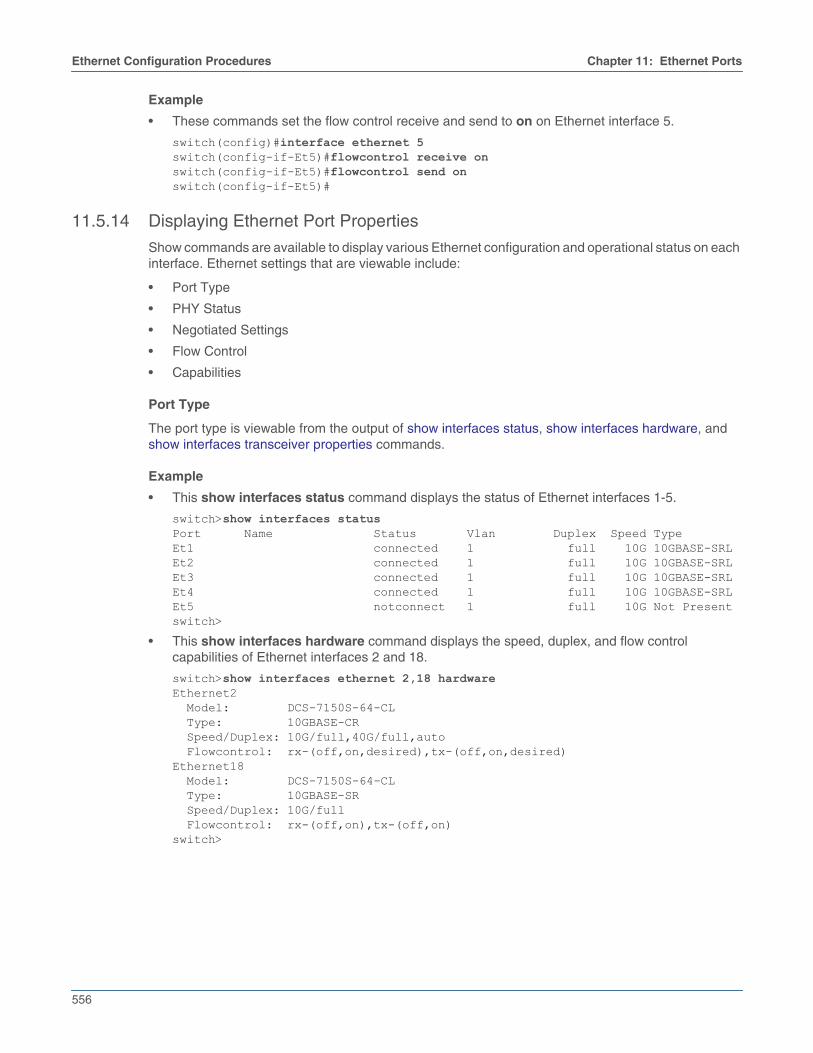
Example
• These commands set the flow control receive and send to on on Ethernet interface 5.
switch(config)#interface ethernet 5switch(config-if-Et5)#flowcontrol receive onswitch(config-if-Et5)#flowcontrol send onswitch(config-if-Et5)#
11.5.14 Displaying Ethernet Port Properties
Show commands are available to display various Ethernet configuration and operational status on eachinterface. Ethernet settings that are viewable include:
• Port Type
• PHY Status
• Negotiated Settings
• Flow Control
• Capabilities
Port Type
The port type is viewable from the output of show interfaces status, show interfaces hardware, andshow interfaces transceiver properties commands.
Example
• This show interfaces status command displays the status of Ethernet interfaces 1-5.
switch>show interfaces statusPort Name Status Vlan Duplex Speed TypeEt1 connected 1 full 10G 10GBASE-SRLEt2 connected 1 full 10G 10GBASE-SRLEt3 connected 1 full 10G 10GBASE-SRLEt4 connected 1 full 10G 10GBASE-SRLEt5 notconnect 1 full 10G Not Presentswitch>
• This show interfaces hardware command displays the speed, duplex, and flow controlcapabilities of Ethernet interfaces 2 and 18.
switch>show interfaces ethernet 2,18 hardwareEthernet2 Model: DCS-7150S-64-CL Type: 10GBASE-CR Speed/Duplex: 10G/full,40G/full,auto Flowcontrol: rx-(off,on,desired),tx-(off,on,desired)Ethernet18 Model: DCS-7150S-64-CL Type: 10GBASE-SR Speed/Duplex: 10G/full Flowcontrol: rx-(off,on),tx-(off,on)switch>

Chapter 11: Ethernet Ports Ethernet Configuration Procedures
557
• This command displays the media type, speed, and duplex properties for Ethernet interfaces 1.
switch>show interfaces ethernet 1 transceiver propertiesName : Et1Administrative Speed: 10GAdministrative Duplex: fullOperational Speed: 10G (forced)Operational Duplex: full (forced)Media Type: 10GBASE-SRL
PHY
PHY information for each Ethernet interface is viewed by entering the show interfaces phy command.
Example
• This command summarizes PHY information for Ethernet interfaces 1-3.
switch>show interfaces ethernet 1-3 phyKey: U = Link up D = Link down R = RX Fault T = TX Fault B = High BER L = No Block Lock A = No XAUI Lane Alignment 0123 = No XAUI lane sync in lane N
State ResetPort PHY state Changes Count PMA/PMD PCS XAUI-------------- --------------- -------- -------- ------- ----- --------Ethernet1 linkUp 14518 1750 U.. U.... U.......Ethernet2 linkUp 13944 1704 U.. U.... U.......Ethernet3 detectingXcvr 3 1 D..A0123switch>
Negotiated Settings
Speed, duplex, and flow control settings are displayed through the show interfaces hardware, PHYinformation for each Ethernet interface is viewed by entering the show interfaces hardware, showinterfaces flow-control, and show interfaces status commands.
Example
• This command displays speed/duplex and flow control settings for Ethernet interface 1.
switch>show interfaces ethernet 1 hardwareEthernet1 Model: DCS-7150S-64-CL Type: 10GBASE-SR Speed/Duplex: 10G/full Flowcontrol: rx-(off,on),tx-(off,on)switch>

558
Ethernet Configuration Procedures Chapter 11: Ethernet Ports
• This command shows the flow control settings for Ethernet interfaces 1-2.
switch>show flow-control interface ethernet 1-2Port Send FlowControl Receive FlowControl RxPause TxPause admin oper admin oper--------- -------- -------- -------- -------- ------------- -------------Et1 off off off off 0 0Et2 off off off off 0 0switch>
• This command displays the speed type and duplex settings for management interfaces 1-2.
switch>show interfaces management 1-2 statusPort Name Status Vlan Duplex Speed TypeMa1 connected routed a-full a-100M 10/100/1000Ma2 connected routed a-full a-1G 10/100/1000switch>
11.5.15 Ingress Counters
The Ingress counters enables the switch to count the ingress traffic on the Layer 3 ports of the switch.Any ingress traffic on Layer 3 sub-interfaces and VLAN interface with IPv4 and IPv6 addresses areaccounted irrespective of the routing decision. The VLAN counters are supported on DCS- 7050x,DCS-7250x, and DCS-7300x series switches and not supported on any routed ports.
11.5.15.1 Configuring Ingress Counters
The hardware counter feature in command enables the switch to count the ingress traffic on the Layer3 port of the switch. Any traffic on Layer 3 sub-interfaces and VLAN interface with IPv4 and IPv6addresses are accounted irrespective of the routing decision.
• This command configures the ingress traffic count on the sub-interfaces. The no form of thecommand disable the counter configuration from the switch ports.
switch#hardware counter feature subinterface in
• This command configures the ingress traffic count on the VLAN interface. The no form of thecommand disable the counter configuration from the VLAN configured switch ports.
switch#hardware counter feature vlan-interface in
11.5.15.2 Displaying the Ingress Counter Information
The show interface counters command displays the Layer 3 ingress traffic count information. Runthis command to view the traffic counts on a sub-interface or VLAN interface of the switch. The clearcounters command resets the counters to zero.
• This command displays the ingress traffic count on a VLAN interface vl12.
switch#show interface vl12 counters incomingL3 Interface InOctets InUcastPkts InMcastPktsVl12 3136 47 2
11.5.16 Configuring Ingress Traffic-Class Counters
Ingress traffic class counter support is enabled in order to display per traffic-class counters on ingressinterfaces, and supported on routed-ports and subinterfaces. Both packet and octet counts aredisplayed.

Chapter 11: Ethernet Ports Ethernet Configuration Procedures
559
Example
• This command enables traffic-class counter support.
switch(config)#hardware counter feature traffic-class inswitch(config)#
• This command enables TCAM profile ‘tc-counters’ if this profile is configured.
switch(config)#hardware tcam profile tc-countersswitch(config)#
11.5.17 Configuring Power over Ethernet (PoE)
Power over Ethernet (PoE) is enabled by default on all Ethernet ports of PoE-capable switches, and theswitch will detect IEEE-compliant powered devices (PDs) when they are plugged into a port and supplypower appropriately.
Limitations
• Ethernet ports will not detect non IEEE-compliant devices by default, and may not be able to detector power them even if configured to do so.
• If attached PDs overload the switch, it will power off. This can occur when an attached PDincreases its power demand via LLDP, when too many PDs are connected to the switch, or whena power supply fails on a heavily loaded dual-supply switch.
• Power-cycling the switch will cause temporary loss of power to attached PDs.
• PoE is not available on management interfaces.
Disabling PoE on an Interface
On switches which support PoE, it is enabled by default on all Ethernet ports but can be disabledper-port with the poe disabled command.
Example
• These commands disable PoE on Ethernet interface 5.
switch(config)#interface ethernet 5switch(config-if-Et5)#poe disabledswitch(config-if-Et5)#
PoE Power Settings
When an IEEE-compliant powered device (PD) is connected to a PoE-enabled Ethernet port, it isrecognized by a specific resistor signature, and its initial power needs are determined by hardwarenegotiation, after which further negotiation is managed through the Link Layer Discovery Protocol(LLDP). For details, see Configuring LLDP for Power over Ethernet.
PoE power output can be limited on a port using the poe limit command. The power limit representsthe power output at the Ethernet port; actual power delivered to the PD will be lower due to power lossalong the Ethernet cable.
Note LLDP uses Power Via MDI type-length-value elements (TLVs) to allow the switch to dynamicallynegotiate power needs with PDs. LLDP will not include Power Via MDI TLVs for the interface if a powerlimit has been configured on it.
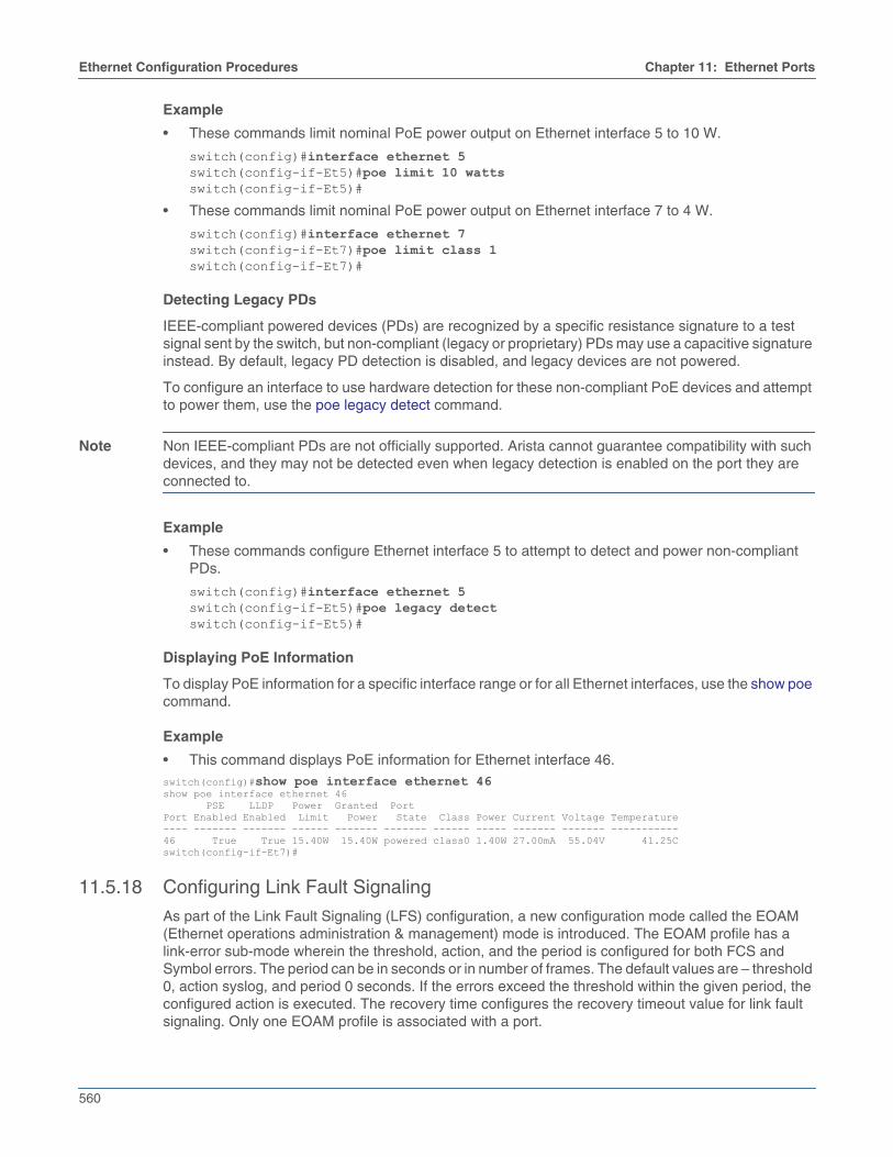
560
Ethernet Configuration Procedures Chapter 11: Ethernet Ports
Example
• These commands limit nominal PoE power output on Ethernet interface 5 to 10 W.
switch(config)#interface ethernet 5switch(config-if-Et5)#poe limit 10 wattsswitch(config-if-Et5)#
• These commands limit nominal PoE power output on Ethernet interface 7 to 4 W.
switch(config)#interface ethernet 7switch(config-if-Et7)#poe limit class 1switch(config-if-Et7)#
Detecting Legacy PDs
IEEE-compliant powered devices (PDs) are recognized by a specific resistance signature to a testsignal sent by the switch, but non-compliant (legacy or proprietary) PDs may use a capacitive signatureinstead. By default, legacy PD detection is disabled, and legacy devices are not powered.
To configure an interface to use hardware detection for these non-compliant PoE devices and attemptto power them, use the poe legacy detect command.
Note Non IEEE-compliant PDs are not officially supported. Arista cannot guarantee compatibility with suchdevices, and they may not be detected even when legacy detection is enabled on the port they areconnected to.
Example
• These commands configure Ethernet interface 5 to attempt to detect and power non-compliantPDs.
switch(config)#interface ethernet 5switch(config-if-Et5)#poe legacy detectswitch(config-if-Et5)#
Displaying PoE Information
To display PoE information for a specific interface range or for all Ethernet interfaces, use the show poecommand.
Example
• This command displays PoE information for Ethernet interface 46.switch(config)#show poe interface ethernet 46show poe interface ethernet 46 PSE LLDP Power Granted PortPort Enabled Enabled Limit Power State Class Power Current Voltage Temperature---- ------- ------- ------ ------- ------- ------ ----- ------- ------- -----------46 True True 15.40W 15.40W powered class0 1.40W 27.00mA 55.04V 41.25Cswitch(config-if-Et7)#
11.5.18 Configuring Link Fault Signaling
As part of the Link Fault Signaling (LFS) configuration, a new configuration mode called the EOAM(Ethernet operations administration & management) mode is introduced. The EOAM profile has alink-error sub-mode wherein the threshold, action, and the period is configured for both FCS andSymbol errors. The period can be in seconds or in number of frames. The default values are – threshold0, action syslog, and period 0 seconds. If the errors exceed the threshold within the given period, theconfigured action is executed. The recovery time configures the recovery timeout value for link faultsignaling. Only one EOAM profile is associated with a port.

Chapter 11: Ethernet Ports Ethernet Configuration Procedures
561
The following steps enable configuring the LFS parameters:
Step 1 Enable the EOAM mode.
switch(config)#monitor ethernet oam
Step 2 Create an EOAM profile named as profile1.
switch(config-eoam)#profile profile1
Step 3 Enter the EOAM link-error sub-mode.
switch(config-eoam-profile-profile1)#link-error
Step 4 Enter the commands in the profile link-error submode to configure a specific LFS parameter.
switch(config-eoam-profile-profile1-link-error)#symbol action errdisableswitch(config-eoam-profile-profile1-link-error)#symbol period 300 framesswitch(config-eoam-profile-profile1-link-error)#symbol threshold 20switch(config-eoam-profile-profile1-link-error)#recovery-time 40
Step 5 Apply the EOAM profile profile1 to the Ethernet interface 1/1.
switch(config)#interface ethernet 1/1switch(config-if-Et1/1)#monitor ethernet oam profile profile1
Platform Compatibility
LFS parameter configuration is supported on the following platforms:
• DCS-7020
• DCS-7050X
• DCS-7060X
• DCS-7250X
• DCS-7260X
• DCS-7280R
• DCS-7300
• DCS-7320
• DCS-7500R
Note The link fault action is not supported on the DCS-7050X, DCS-7250X, DCS-7060X, DCS-7260X,DCS-7300, DCS-7320 platforms.
11.5.19 Configuring Hardware TCAM
TCAM (ternary content-addressable memory) is a specialized type of high-speed memory thatincrease the speed of route look-up, packet classification, packet forwarding and access controllist-based commands. The hardware tcam command is used to configure and place the switch in theTCAM mode. In this mode the user can configure few TCAM related commands such as feature, profileand system.
In the TCAM mode the feature command is used to configure the reservation of TCAM banks for thefeatures like ACL, IPsec, flow-spec, l2-protocol, PBR, QoS, TCP-MSS-ceiling, traffic-policy. The profilecommand configures a new TCAM profile, or just copy the TCAM profile which is already created usingthe hardware tcam profile command such as default, mirroring-acl, pbr-match-nexthop-group, qos,tap-aggregation-default, tap-aggregation-extended, tc-counters, test, vxlan-routing. Similarly, thesystem command configures the system-wide TCAM profiles.

562
Ethernet Configuration Procedures Chapter 11: Ethernet Ports
Examples• This command places the switch in Hardware TCAM configuration mode.
switch(config)#hardware tcamswitch(config-hw-tcam)#
These are the commands allowed to configure in Hardware TCAM mode.
• This commands allow the switch to configure the TCAM feature.
switch(config)#hardware tcamswitch(config-hw-tcam)#feature
• This commands allow the switch to configure TCAM profile.
switch(config)#hardware tcamswitch(config-hw-tcam)#profile
• This commands allow the switch to configure TCAM system profile.
switch(config)#hardware tcamswitch(config-hw-tcam)#system
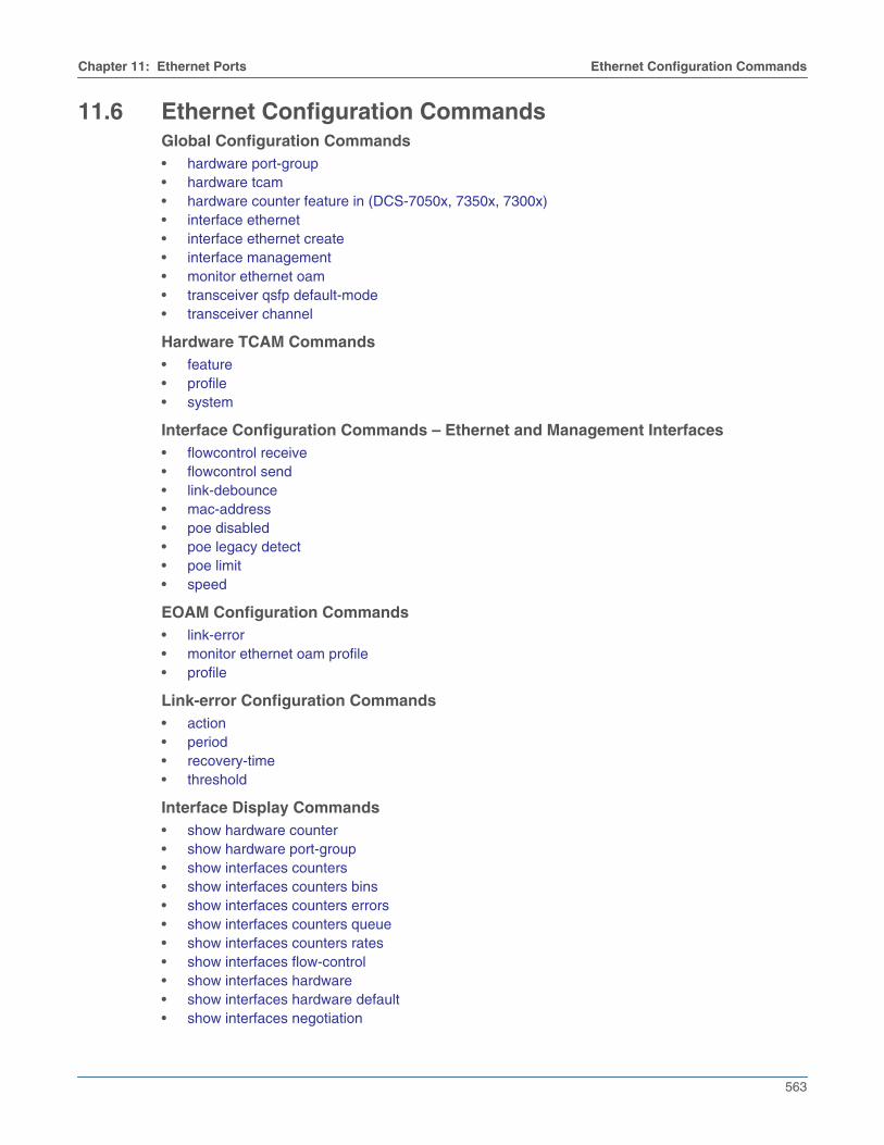
Chapter 11: Ethernet Ports Ethernet Configuration Commands
563
11.6 Ethernet Configuration CommandsGlobal Configuration Commands• hardware port-group• hardware tcam• hardware counter feature in (DCS-7050x, 7350x, 7300x)• interface ethernet• interface ethernet create• interface management• monitor ethernet oam• transceiver qsfp default-mode• transceiver channel
Hardware TCAM Commands• feature• profile• system
Interface Configuration Commands – Ethernet and Management Interfaces• flowcontrol receive• flowcontrol send• link-debounce• mac-address• poe disabled• poe legacy detect• poe limit• speed
EOAM Configuration Commands• link-error• monitor ethernet oam profile• profile
Link-error Configuration Commands• action• period• recovery-time• threshold
Interface Display Commands• show hardware counter• show hardware port-group• show interfaces counters• show interfaces counters bins• show interfaces counters errors• show interfaces counters queue• show interfaces counters rates• show interfaces flow-control• show interfaces hardware• show interfaces hardware default• show interfaces negotiation

564
Ethernet Configuration Commands Chapter 11: Ethernet Ports
• show interfaces phy• show interfaces status• show interfaces status errdisabled• show interfaces transceiver• show interfaces transceiver channels• show interfaces transceiver hardware• show interfaces transceiver properties• show monitor ethernet oam profile• show platform fm6000 agileport map• show poe

Chapter 11: Ethernet Ports Ethernet Configuration Commands
565
action
The action command configures the link monitoring action that is specified for the link fault signalingevent.
The no action command removes the action type specified for the chosen link fault signaling. Thedefault action command configures the link monitoring action as system log type.
Command ModeLink-error Configuration
Command Syntax{fcs | symbol} action [linkfault | errdisable | log]no {fcs | symbol} action [linkfault | errdisable | log]default {fcs | symbol} action [linkfault | errdisable | log]
Parameters• fcs Inbound packets with frame check sequence (FCS) error.
• symbol Inbound packets with symbol error.
• linkfault The link fault action type.
• errdisable The errdisable action type.
• log The system log action type.
Related Commands• period
• threshold
Example• These commands set the errdisable action type for the profile profile1 in the Link-error
configuration mode for symbol errors.
switch(config)#monitor ethernet oamswitch(config-eoam)#profile profile1switch(config-eoam-profile-profile1)#link-errorswitch(config-eoam-profile-profile1-link-error)#symbol action errdisable
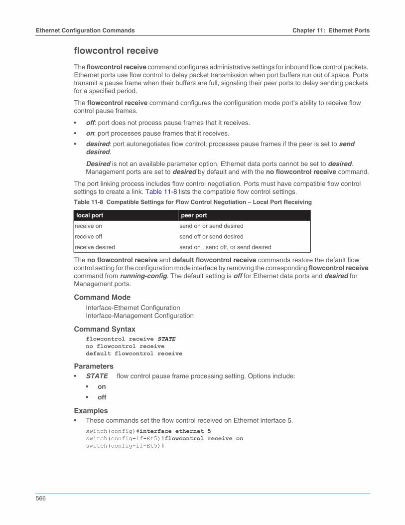
566
Ethernet Configuration Commands Chapter 11: Ethernet Ports
flowcontrol receive
The flowcontrol receive command configures administrative settings for inbound flow control packets.Ethernet ports use flow control to delay packet transmission when port buffers run out of space. Portstransmit a pause frame when their buffers are full, signaling their peer ports to delay sending packetsfor a specified period.
The flowcontrol receive command configures the configuration mode port's ability to receive flowcontrol pause frames.
• off: port does not process pause frames that it receives.
• on: port processes pause frames that it receives.
• desired: port autonegotiates flow control; processes pause frames if the peer is set to senddesired.
Desired is not an available parameter option. Ethernet data ports cannot be set to desired.Management ports are set to desired by default and with the no flowcontrol receive command.
The port linking process includes flow control negotiation. Ports must have compatible flow controlsettings to create a link. Table 11-8 lists the compatible flow control settings.
The no flowcontrol receive and default flowcontrol receive commands restore the default flowcontrol setting for the configuration mode interface by removing the corresponding flowcontrol receivecommand from running-config. The default setting is off for Ethernet data ports and desired forManagement ports.
Command ModeInterface-Ethernet ConfigurationInterface-Management Configuration
Command Syntaxflowcontrol receive STATEno flowcontrol receivedefault flowcontrol receive
Parameters• STATE flow control pause frame processing setting. Options include:
• on
• off
Examples• These commands set the flow control received on Ethernet interface 5.
switch(config)#interface ethernet 5switch(config-if-Et5)#flowcontrol receive onswitch(config-if-Et5)#
Table 11-8 Compatible Settings for Flow Control Negotiation – Local Port Receiving
local port peer port
receive on send on or send desired
receive off send off or send desired
receive desired send on , send off, or send desired

Chapter 11: Ethernet Ports Ethernet Configuration Commands
567
flowcontrol send
The flowcontrol send command configures administrative settings for outbound flow control packets.Ethernet ports use flow control to delay packet transmission when port buffers run out of space. Portstransmit a pause frame when their buffers are full, signaling their peer ports to delay sending packetsfor a specified period.
The flowcontrol send command configures the configuration mode port's ability to transmit flowcontrol pause frames.
• off: port does not send pause frames.
• on: port sends pause frames.
• desired: port autonegotiates flow control; sends pause frames if the peer is set to receive desired.
Desired is not an available parameter option. Ethernet data ports cannot be set to desired.Management ports are set to desired by default and with the no flowcontrol send command.
The port linking process includes flow control negotiation. Ports must have compatible flow controlsettings to create a link. Table 11-9 lists the compatible flow control settings.
The no flowcontrol send and default flowcontrol send commands restore the default flow controlsetting for the configuration mode interface by removing the corresponding flowcontrol sendcommand from running-config. The default setting is off for Ethernet data ports and desired forManagement ports.
Command ModeInterface-Ethernet ConfigurationInterface-Management Configuration
Command Syntaxflowcontrol send STATEno flowcontrol senddefault flowcontrol send
Parameters• STATE flow control send setting. Options include
• on
• off
Examples• These commands set the flow control sent on Ethernet interface 5.
switch(config)#interface ethernet 5switch(config-if-Et5)#flowcontrol send onswitch(config-if-Et5)#
Table 11-9 Compatible Settings for Flow Control Negotiation – Local Port Transmitting
local port peer port
send on receive on or receive desired
send off receive off or receive desired
send desired receive on , receive off, or receive desired

568
Ethernet Configuration Commands Chapter 11: Ethernet Ports
hardware port-group
The hardware port-group command configures a port group to activate a 40GBASE (QSFP+)interface or four 10GBASE (SFP+) interfaces, affecting QSFP+ and SFP+ availability.
The no hardware port-group and default hardware port-group commands restore a port group’sdefault setting by removing the corresponding hardware port-group command from running-config.The QSFP+ interface is active by default in each port group.
The hardware port-group command is available on DCS-7050Q-16 and DCS-7050QX-32S switches,and has different parameters on each platform.
Command ModeGlobal Configuration
Command Syntaxhardware port-group group_number select PORT_LISTno hardware port-group group_numberdefault hardware port-group group_number
Parameters• group_number label of the port group. Valid options are 1 and 2 on the 7050Q-16; only 1 is
available on the 7050QX-32S.
• PORT_LIST ports activated by command. Options vary by platform and depend ongroup_number value.
DCS-7050Q-16
• Et15/1-4 activates QSFP+ port on port group 1. Available when group_number is 1.
• Et16/1-4 activates QSFP+ port on port group 2. Available when group_number is 2.
• Et17-20 activates SFP+ ports on port group 1. Available when group_number is 1.
• Et21-23 activates SFP+ ports on port group 2. Available when group_number is 2.
DCS-7050QX-32S
• Et1-4 activates SFP+ ports on port group 1. Available when group_number is 1.
• Et5/1-4 activates QSFP+ port on port group 1. Available when group_number is 1.
Chapter 11: Ethernet Ports Ethernet Configuration Commands
569
hardware tcam
The hardware tcam command places the switch in Hardware TCAM configuration mode.
The exit command returns the switch to global configuration mode.
Command ModeGlobal Configuration
Command Syntaxhardware tcam
Example• This command places the switch in Hardware TCAM configuration mode.
switch(config)#hardware tcamswitch(config-hw-tcam)#
Commands Available• feature
• profile
• system
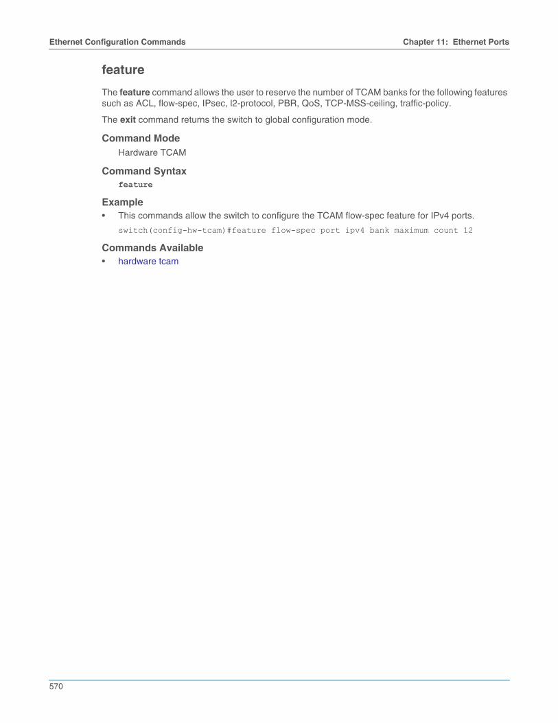
570
Ethernet Configuration Commands Chapter 11: Ethernet Ports
feature
The feature command allows the user to reserve the number of TCAM banks for the following featuressuch as ACL, flow-spec, IPsec, l2-protocol, PBR, QoS, TCP-MSS-ceiling, traffic-policy.
The exit command returns the switch to global configuration mode.
Command ModeHardware TCAM
Command Syntaxfeature
Example• This commands allow the switch to configure the TCAM flow-spec feature for IPv4 ports.
switch(config-hw-tcam)#feature flow-spec port ipv4 bank maximum count 12
Commands Available• hardware tcam

Chapter 11: Ethernet Ports Ethernet Configuration Commands
571
profile
The profile command allows the user to configure a new TCAM profile, or just copy the TCAM profilewhich is already created using the hardware tcam profile command such as default, mirroring-acl,pbr-match-nexthop-group, qos, tap-aggregation-default, tap-aggregation-extended, tc-counters, test,vxlan-routing.
The exit command returns the switch to global configuration mode.
Command ModeHardware TCAM
Command Syntaxprofile <name>
Parameter• name TCAM profile name.
Example• This commands allow the switch to configure the TCAM profile “test”.
switch(config-hw-tcam)#profile testCommands Available• hardware tcam

572
Ethernet Configuration Commands Chapter 11: Ethernet Ports
system
The system command allows the user to configure the system-wide TCAM profiles such as default,mirroring-acl, mpls-evpn, pbr-match-nexthop-group, qos, tap-aggregation-default,tap-aggregation-extended, tc-counters, test, vxlan-routing.
The exit command returns the switch to global configuration mode.
Command ModeHardware TCAM
Command Syntaxsystem profile <name>
Parameter• name TCAM profile name.
Example• This commands allow the switch to configure the TCAM profile “qos”.
switch(config-hw-tcam)#system profile qosCommands Available• hardware tcam

Chapter 11: Ethernet Ports Ethernet Configuration Commands
573
hardware counter feature in (DCS-7050x, 7350x, 7300x)
The hardware counter feature in command enables the switch to count the ingress traffic on the Layer3 port of the switch. Any traffic on Layer 3 sub-interfaces and VLAN interface with IPv4 and IPv6addresses are accounted irrespective of the routing decision.
The no hardware counter feature in command disable the counter configuration from the switchports. By default the ingress counter is disabled on the switch.
Command ModeGlobal Configuration
Command Syntaxhardware counter feature [INTERFACE] inno hardware counter feature [INTERFACE] in
Parameters• INTERFACE Layer 3 interface on the switch.
• subinterface Displays the subinterface traffic count.
• vlan-interface Displays the VLAN-interface traffic count.
Examples• This command configures the ingress traffic count on the sub-interfaces.
switch#hardware counter feature subinterface in• This command configures the ingress traffic count on the VLAN interface.
switch#hardware counter feature vlan-interface in

574
Ethernet Configuration Commands Chapter 11: Ethernet Ports
Example• These commands enable the QSFP+ interface in port group 1 and SFP+ interfaces in port group
2 on a DCS-7050Q-16 switch, display the port group status, and display interface status.
switch(config)#hardware port-group 1 select Et15/1-4switch(config)#hardware port-group 2 select Et21-24switch(config)#show hardware port-group
Portgroup: 1 Active Ports: Et17-20Port State------------------------------------------Ethernet17 ErrDisabledEthernet18 ErrDisabledEthernet19 ErrDisabledEthernet20 ErrDisabledEthernet15/1 ActiveEthernet15/2 ActiveEthernet15/3 ActiveEthernet15/4 Active
Portgroup: 2 Active Ports: Et16/1-4Port State------------------------------------------Ethernet16/1 ActiveEthernet16/2 ActiveEthernet16/3 ActiveEthernet16/4 ActiveEthernet21 ErrDisabledEthernet22 ErrDisabledEthernet23 ErrDisabledEthernet24 ErrDisabledswitch(config)#show interfaces statusPort Name Status Vlan Duplex Speed TypeEt1/1 connected in Po621 full 40G 40GBASE-CR4Et1/2 errdisabled inactive unconf unconf 40GBASE-CR4<-------OUTPUT OMITTED FROM EXAMPLE-------->Et15/1 connected in Po711 full 40G 40GBASE-CR4Et15/2 errdisabled inactive unconf unconf Not PresentEt15/3 errdisabled inactive unconf unconf Not PresentEt15/4 errdisabled inactive unconf unconf Not PresentEt16/1 errdisabled inactive unconf unconf Not PresentEt16/2 errdisabled inactive unconf unconf Not PresentEt16/3 errdisabled inactive unconf unconf Not PresentEt16/4 errdisabled inactive unconf unconf Not PresentEt17 errdisabled inactive unconf unconf Not PresentEt18 errdisabled inactive unconf unconf Not PresentEt19 errdisabled inactive unconf unconf Not PresentEt20 errdisabled inactive unconf unconf Not PresentEt21 connected 425 full 10G 10GBASE-SRLEt22 connected 611 full 10G 10GBASE-SRLEt23 connected in Po998 full 10G 10GBASE-SLREt24 connected in Po998 full 10G 10GBASE-SLRswitch(config)#

Chapter 11: Ethernet Ports Ethernet Configuration Commands
575
interface ethernet
The interface ethernet command places the switch in Ethernet-interface configuration mode for thespecified interfaces. The command can specify a single interface or multiple interfaces.
Ethernet interfaces are physical interfaces and are not created or removed.
Interface management commands include:
• description
• exit
• load-interval
• mtu
• shutdown (Interfaces)
Ethernet management commands include:
• flowcontrol
• mac-address
• speed
Chapters describing supported protocols and other features list additional configuration commandsavailable from Ethernet interface configuration mode.
Command ModeGlobal Configuration
Command Syntaxinterface ethernet e_range
Parameters• e_range Ethernet interfaces (number, range, or comma-delimited list of numbers and ranges).
Valid Ethernet numbers depend on the switch’s available Ethernet interfaces.
Example• This command enters interface configuration mode for Ethernet interfaces 1 and 2:
switch(config)#interface ethernet 1-2switch(config-if-Et1-2)#
• This command enters interface configuration mode for Ethernet interface 1:
switch(config)#interface ethernet 1switch(config-if-Et1)#

576
Ethernet Configuration Commands Chapter 11: Ethernet Ports
interface ethernet create
The interface ethernet create command is used to configure a range of Ethernet subinterfaces. Thecommand places the switch in Ethernet-interface configuration mode for the specified range ofsubinterfaces.
Command ModeGlobal Configuration
Command Syntaxinterface ethernet create sub_range
Parameters• sub_range range of subinterfaces to be configured. Subinterfaces are named by adding a period
followed by a unique subinterface number to the name of the parent interface.
Example• This command enters interface configuration mode for Ethernet subinterfaces 1/1.1-100:
switch(config)#interface ethernet create 1/1.100switch(config-if-Et1/1.1-100)#

Chapter 11: Ethernet Ports Ethernet Configuration Commands
577
interface management
The interface management command places the switch in management-interface configuration modefor the specified interfaces. The list can specify a single interface or multiple interfaces if the switchcontains more than one management interface.
Management interfaces are physical interfaces and are not created or removed.
Interface management commands include:
• description
• exit
• load-interval
• mtu
• shutdown (Interfaces)
Ethernet management commands include:
• flowcontrol
• mac-address
• speed
Chapters describing supported protocols and other features list additional configuration commandsavailable from management-interface configuration mode.
Command ModeGlobal Configuration
Command Syntaxinterface management m_range
Parameters• m_range Management interfaces (number, range, or comma-delimited list of numbers and
ranges).
Valid management numbers depend on the switch’s available management interfaces. A value of0, where available, configures the virtual management interface on a dual-supervisor modularswitch. Management interface 0 accesses management port 1 on the active supervisor of adual-supervisor modular switch.
Examples• This command enters interface configuration mode for management interfaces 1 and 2.
switch(config)#interface management 1-2switch(config-if-Ma1-2)#
• This command enters interface configuration mode for management interface 1:
switch(config)#interface management 1switch(config-if-Ma1)#

578
Ethernet Configuration Commands Chapter 11: Ethernet Ports
link-debounce
The link-debounce command configures the link debounce time for the configuration mode interface.Link debounce time is the time that advertisements for new link states are delayed after the link stateis established. By default, debounce time is set to zero, disabling link debounce.
Debounce times for link-up and link-down transitions can be independently configured.
• Link-up debounce time: the delay before an interface advertises link down to link up transitions.
• Link-down debounce time: the delay before an interface advertises link up to link down transitions.
The no link-debounce and default link-debounce commands restore the default debounce settingfor the configuration mode interface by removing the corresponding link-debounce command fromrunning-config.
Command ModeInterface-Ethernet ConfigurationInterface-Management Configuration
Command Syntaxlink-debounce time WAIT_TIMEno link-debouncedefault link-debounce
Parameters• WAIT_TIME link debounce period (milliseconds). Options include
• <0 - 30000> One debounce value assigned as both link up and link down.
• <0 - 30000> <0 - 30000> Two debounce values: link up is first, link down is second.
All debounce values range from 0 (disabled) to 30000 (30 seconds).
Examples• These commands set the link-up and link-down debounce period to 10 seconds on Ethernet
interface 5.
switch(config)#interface ethernet 5switch(config-if-Et5)#link-debounce time 10000switch(config-if-Et5)#
• These commands set the link-up debounce to 10 seconds and the link-down debounce period tozero on Ethernet interface 5.
switch(config)#interface ethernet 5switch(config-if-Et5)#link-debounce time 10000 0switch(config-if-Et5)#
• These commands set the link-up debounce to zero and the link-down debounce period to 12.5seconds on Ethernet interface 5.
switch(config)#interface ethernet 5switch(config-if-Et5)#link-debounce time 0 12500switch(config-if-Et5)#

Chapter 11: Ethernet Ports Ethernet Configuration Commands
579
link-error
The link-error command places the Ethernet operations, administration, and management (EOAM)profile in the EOAM link-error sub-mode.
The no link-error and default link-error commands exit from the EOAM link-error sub-mode.
Command ModeEOAM Configuration
Command Syntaxlink-errorno link-errordefault link-error
Related Commands• monitor ethernet oam profile
• show monitor ethernet oam profile
Example• These commands place the EOAM profile profile1 in the link-error sub-mode.
switch(config)#monitor ethernet oamswitch(config-eoam)#profile profile1switch(config-eoam-profile-profile1)#link-errorswitch(config-eoam-profile-profile1-link-error)#

580
Ethernet Configuration Commands Chapter 11: Ethernet Ports
mac-address
The mac-address command assigns a MAC address to the configuration mode interface. Aninterface’s default MAC address is its burn-in address.
The no mac-address and default mac-address commands revert the interface to its default MACaddress by removing the corresponding mac-address command from running-config.
Command ModeInterface-Ethernet ConfigurationInterface-Management Configuration
Command Syntaxmac-address addressno mac-addressdefault mac-address
Parameters• address MAC address assigned to the interface. Format is dotted hex notation (H.H.H).
Disallowed addresses are 0.0.0 and FFFF.FFFF.FFFF.
Example• This command assigns the MAC address of 001c.2804.17e1 to Ethernet interface 7, then displays
interface parameters, including the assigned address.
switch(config)#interface ethernet 7switch(config-if-Et7)#mac-address 001c.2804.17e1switch(config-if-Et7)#show interface ethernet 7Ethernet3 is up, line protocol is up (connected) Hardware is Ethernet, address is 001c.2804.17e1 (bia 001c.7312.02e2) Description: b.e45 MTU 9212 bytes, BW 10000000 Kbit Full-duplex, 10Gb/s, auto negotiation: off Last clearing of "show interface" counters never 5 seconds input rate 7.84 kbps (0.0% with framing), 10 packets/sec 5 seconds output rate 270 kbps (0.0% with framing), 24 packets/sec 1363799 packets input, 222736140 bytes Received 0 broadcasts, 290904 multicast 0 runts, 0 giants 0 input errors, 0 CRC, 0 alignment, 0 symbol 0 PAUSE input 2264927 packets output, 2348747214 bytes Sent 0 broadcasts, 28573 multicast 0 output errors, 0 collisions 0 late collision, 0 deferred 0 PAUSE outputswitch(config-if-Et7)#

Chapter 11: Ethernet Ports Ethernet Configuration Commands
581
monitor ethernet oam
The monitor ethernet oam command places the switch in the Ethernet operations, administration, andmanagement (EOAM) configuration mode.
The no monitor ethernet oam and default monitor ethernet oam commands exit from the EOAMconfiguration mode.
Command ModeGlobal Configuration
Command Syntaxmonitor ethernet oamno monitor ethernet oamdefault monitor ethernet oam
Example• This command places the switch in the EOAM configuration mode.
switch(config)#monitor ethernet oamswitch(config-eoam)#

582
Ethernet Configuration Commands Chapter 11: Ethernet Ports
monitor ethernet oam profile
The monitor ethernet oam profile command applies the EOAM profile to the specific interface ininterface configuration mode.
The no monitor ethernet oam profile and default monitor ethernet oam profile commands removethe EOAM profile from the interface.
Command ModeInterface Configuration
Command Syntaxmonitor ethernet oam profile nameno monitor ethernet oam profiledefault monitor ethernet oam profile
Parameters• name The EOAM profile name. An EOAM profile cannot be named as summary.
Related Commands• link-error
• show monitor ethernet oam profile
Example• These commands apply the EOAM profile profile1 to the Ethernet interface 1/1.
switch(config)#interface ethernet 1/1switch(config-if-Et1/1)#monitor ethernet oam profile profile1

Chapter 11: Ethernet Ports Ethernet Configuration Commands
583
period
The period command configures the link monitoring period that is specified for a link error in terms ofnumber of frames or seconds.
The no period command removes the period type specified on the chosen link error. The defaultperiod command configures the link monitoring period as zero seconds.
Command ModeLink-error Configuration
Command Syntax{fcs | symbol} period num {seconds | frames}no {fcs | symbol} period num {seconds | frames}default {fcs | symbol} period num {seconds | frames}
Parameters• fcs Inbound packets with frame check sequence (FCS) error.
• symbol Inbound packets with symbol error.
• num The link monitoring period in frames or seconds. The frames’ value ranges from 1 to4000000000. The seconds’ value ranges from 2 to 200 seconds. The default value is 2 seconds.
• seconds The monitor errors per num seconds.
• frames The monitor errors per num frames.
Related Commands• action
• threshold
Example• These commands set the frames period type for the profile profile1 in the Link-error configuration
mode for 300 frames.
switch(config)#monitor ethernet oamswitch(config-eoam)#profile profile1switch(config-eoam-profile-profile1)#link-errorswitch(config-eoam-profile-profile1-link-error)#symbol period 300 frames

584
Ethernet Configuration Commands Chapter 11: Ethernet Ports
poe disabled
Power over Ethernet (PoE) is enabled on all Ethernet ports by default on switches that support PoE.The poe disabled command disables PoE on the configuration-mode interface.
The no poe disabled and default poe disabled commands restore PoE on the interface by removingthe corresponding poe disabled command from running-config.
Command ModeInterface-Ethernet Configuration
Command Syntaxpoe disabledno poe disableddefault poe disabled
Example• These commands disable PoE on Ethernet interface 7.
switch(config)#interface ethernet 7switch(config-if-Et7)#poe disabledswitch(config-if-Et7)#

Chapter 11: Ethernet Ports Ethernet Configuration Commands
585
poe legacy detect
IEEE-compliant powered devices (PDs) are recognized by a specific resistance signature to a testsignal sent by the switch, but non-compliant (legacy or proprietary) PDs may use a capacitive signatureinstead. The poe legacy detect command causes the configuration-mode interface to attempt to usehardware detection for these non-compliant PoE devices and power them. By default, legacy PDdetection is disabled, and legacy devices are not powered.
Note Non IEEE-compliant PDs are not officially supported. Arista cannot guarantee compatibility with suchdevices, and they may not be detected even when legacy detection is enabled on the port they areconnected to.
The no poe legacy detect and default poe legacy detect commands restore the default behavior byremoving the corresponding poe legacy detect command from running-config.
Command ModeInterface-Ethernet Configuration
Command Syntaxpoe legacy detectno poe legacy detectdefault poe legacy detect
Example• These commands configure Ethernet interface 7 to attempt to detect and power capacitive PDs.
switch(config)#interface ethernet 7switch(config-if-Et7)#poe legacy detectswitch(config-if-Et7)#

586
Ethernet Configuration Commands Chapter 11: Ethernet Ports
poe limit
Power over Ethernet (PoE) power output is limited by the hardware-negotiated power level and by thetotal power capacity of the switch. The poe limit command sets an additional maximum power outputfor the configuration-mode interface. The power limit represents the power output at the Ethernet port;actual power delivered to the PD will be lower due to power loss along the Ethernet cable.
Note If a power limit is set by this command, Power Via MDI TLVs will not be sent from the interface. SeeConfiguring LLDP for Power over Ethernet for details.
The no poe limit and default poe limit commands restore the default power limitation by removingthe corresponding poe limit command from running-config.
Command ModeInterface-Ethernet Configuration
Command Syntaxpoe limit {class class_num | watt_num watts}no poe limitdefault poe limit
Parameters• class_num specifies the power output limit by power class. Values range from 0-6 as follows:
• Class 0 = 15.4 W
• Class 1 = 4 W
• Class 2 = 7 W
• Class 3 = 15.4 W
• Class 4 = 30 W
• Class 5 = 45 W
• Class 6 = 60 W
• watt_num specifies the power output limit in watts. Values range from 0-60. A value of 0 wattswill prevent the port from providing PoE power.
Example• These commands limit nominal PoE power output on Ethernet interface 7 to 10 W.
switch(config)#interface ethernet 7switch(config-if-Et7)#poe limit 10 wattsswitch(config-if-Et7)#
• These commands limit nominal PoE power output on Ethernet interface 7 to 4 W.
switch(config)#interface ethernet 7switch(config-if-Et7)#poe limit class 1switch(config-if-Et7)#
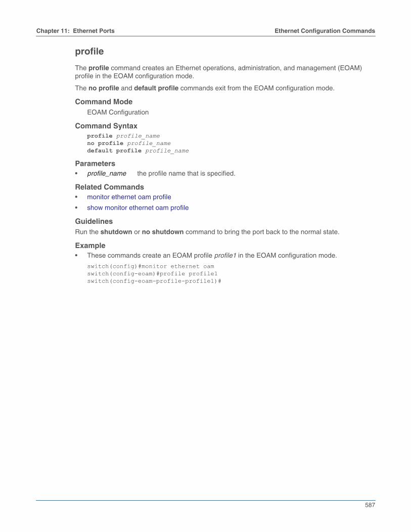
Chapter 11: Ethernet Ports Ethernet Configuration Commands
587
profile
The profile command creates an Ethernet operations, administration, and management (EOAM)profile in the EOAM configuration mode.
The no profile and default profile commands exit from the EOAM configuration mode.
Command ModeEOAM Configuration
Command Syntaxprofile profile_nameno profile profile_namedefault profile profile_name
Parameters• profile_name the profile name that is specified.
Related Commands• monitor ethernet oam profile
• show monitor ethernet oam profile
GuidelinesRun the shutdown or no shutdown command to bring the port back to the normal state.
Example• These commands create an EOAM profile profile1 in the EOAM configuration mode.
switch(config)#monitor ethernet oamswitch(config-eoam)#profile profile1switch(config-eoam-profile-profile1)#

588
Ethernet Configuration Commands Chapter 11: Ethernet Ports
recovery-time
The recovery-time command configures the recovery timeout value for link fault signaling.
The no recovery-time command and the default recovery-time command removes the recoverytimeout value specified for the chosen link error.
Command ModeLink-error Configuration
Command Syntaxrecovery-time valueno recovery-time valuedefault recovery-time value
Parameters• value Specifies the recovery timeout value for LFS. The value ranges from 20 to 200.
Related Commands• action
• period
• threshold
Example• These commands set the recovery time value of 40 for the profile profile1 in the Link-error
configuration mode.
switch(config)#monitor ethernet oamswitch(config-eoam)#profile profile1switch(config-eoam-profile-profile1)#link-errorswitch(config-eoam-profile-profile1-link-error)#recovery-time 40

Chapter 11: Ethernet Ports Ethernet Configuration Commands
589
show hardware counter
The show hardware counter command displays counter events across time intervals.
Command ModeEXEC
Command Syntaxshow hardware counter
Example• This command displays counter events across all time intervals, which are currently more than one
standard deviation apart from a given time interval.
switch(config-handler-eventHandler1-counters)#show hardware counter events-----------------------------------------------------------------------------------------Interval | Event Name | Chip | First | Last | Count | Z-Score | | Name | Occurrence | Occurrence | | -----------------------------------------------------------------------------------------5 Min | MacCounters | All | 2017-01-31 09:31:35 | 2017-01-31 09:44:32 | 5 | -6.943010 Min | MacCounters | All | 2017-01-31 09:39:43 | 2017-01-31 09:44:32 | 3 | -4.8123-----------------------------------------------------------------------------------------switch(config-handler-eventHandler1-counters)#
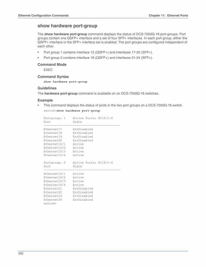
590
Ethernet Configuration Commands Chapter 11: Ethernet Ports
show hardware port-group
The show hardware port-group command displays the status of DCS-7050Q-16 port-groups. Portgroups contain one QSFP+ interface and a set of four SFP+ interfaces. In each port group, either theQSFP+ interface or the SFP+ interface set is enabled. The port groups are configured independent ofeach other.
• Port group 1 contains interface 15 (QSFP+) and interfaces 17-20 (SFP+).
• Port group 2 contains interface 16 (QSFP+) and interfaces 21-24 (SFP+).
Command ModeEXEC
Command Syntaxshow hardware port-group
GuidelinesThe hardware port-group command is available on on DCS-7050Q-16 switches.
Example• This command displays the status of ports in the two port groups on a DCS-7050Q-16 switch.
switch>show hardware port-group
Portgroup: 1 Active Ports: Et15/1-4Port State------------------------------------------Ethernet17 ErrDisabledEthernet18 ErrDisabledEthernet19 ErrDisabledEthernet20 ErrDisabledEthernet15/1 ActiveEthernet15/2 ActiveEthernet15/3 ActiveEthernet15/4 Active
Portgroup: 2 Active Ports: Et16/1-4Port State------------------------------------------Ethernet16/1 ActiveEthernet16/2 ActiveEthernet16/3 ActiveEthernet16/4 ActiveEthernet21 ErrDisabledEthernet22 ErrDisabledEthernet23 ErrDisabledEthernet24 ErrDisabledswitch>

Chapter 11: Ethernet Ports Ethernet Configuration Commands
591
show interfaces counters
The show interface counters command displays the Layer 3 ingress traffic count information. Runthis command to view the traffic counts on a sub-interface or VLAN interface. The clear counterscommand resets the counters to zero. Counters displayed by the command include:
• inbound bytes
• inbound unicast packets
• inbound multicast packets
• inbound broadcast packets
• outbound bytes
• outbound unicast packets
• outbound multicast packets
• outbound broadcast packets
Command ModeEXEC
Command Syntaxshow interfaces [INTERFACE] counters [incoming]
Parameters• INTERFACE Interface type and numbers. Options include:
• <no parameter> all interfaces.
• ethernet e_range Ethernet interface range specified by e_range.
• management m_range Management interface range specified by m_range.
• port-channel p_range Port-Channel Interface range specified by p_range.
• subinterface Displays the subinterface traffic counts.
• vlan-interface Displays the VLAN-interface traffic counts.
• incoming Displays the traffic count for the ingress port.
Note When no interface is specified, the output will start with ingress and egress counters section for regularinterfaces, followed by section for the ingress L3 Interface counters.
Related Commands• show interfaces counters bins
• show interfaces counters errors
• show interfaces counters queue
• show interfaces counters rates
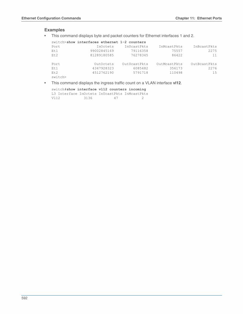
592
Ethernet Configuration Commands Chapter 11: Ethernet Ports
Examples• This command displays byte and packet counters for Ethernet interfaces 1 and 2.
switch>show interfaces ethernet 1-2 countersPort InOctets InUcastPkts InMcastPkts InBcastPktsEt1 99002845169 79116358 75557 2275Et2 81289180585 76278345 86422 11
Port OutOctets OutUcastPkts OutMcastPkts OutBcastPktsEt1 4347928323 6085482 356173 2276Et2 4512762190 5791718 110498 15switch>
• This command displays the ingress traffic count on a VLAN interface vl12.
switch#show interface vl12 counters incomingL3 Interface InOctets InUcastPkts InMcastPktsVl12 3136 47 2

Chapter 11: Ethernet Ports Ethernet Configuration Commands
593
show interfaces counters bins
The show interfaces counters bins command displays packet counters, categorized by packetlength, for the specified interfaces. Packet length counters that the command displays include:
• 64 bytes
• 65-127 bytes
• 128-255 bytes
• 256-511 bytes
• 512-1023 bytes
• 1024-1522 bytes
• larger than 1522 bytes
Command ModeEXEC
Command Syntaxshow interfaces [INTERFACE] counters bins
Parameters• INTERFACE Interface type and numbers. Options include:
• <no parameter> all interfaces.
• ethernet e_range Ethernet interface range specified by e_range.
• management m_range Management interface range specified by m_range.
• port-channel p_range Port-Channel Interface range specified by p_range.
Related Commands• show interfaces counters
• show interfaces counters errors
• show interfaces counters queue
• show interfaces counters rates
Examples• This command displays packet counter results for Ethernet interfaces 1 and 2.
switch>show interfaces ethernet 1-2 counters binsInputPort 64 Byte 65-127 Byte 128-255 Byte 256-511 Byte------------------------------------------------------------------------------Et1 2503 56681135 1045154 1029152Et2 8 50216275 1518179 1086297
Port 512-1023 Byte 1024-1522 Byte 1523-MAX Byte-------------------------------------------------------------Et1 625825 17157823 8246822Et2 631173 27059077 5755101switch>

594
Ethernet Configuration Commands Chapter 11: Ethernet Ports
show interfaces counters errors
The show interfaces counters errors command displays the error counters for the specifiedinterfaces.
Command ModeEXEC
Command Syntaxshow interfaces [INTERFACE] counters errors
Parameters• INTERFACE Interface type and numbers. Options include:
• <no parameter> all interfaces.
• ethernet e_range Ethernet interface range specified by e_range.
• management m_range Management interface range specified by m_range.
• port-channel p_range Port-Channel Interface range specified by p_range.
Display ValuesThe table displays the following counters for each listed interface:
• FCS: Inbound packets with CRC error and proper size.
• Align: Inbound packets with improper size (undersized or oversized).
• Symbol: Inbound packets with symbol error and proper size.
• Rx: Total inbound error packets.
• Runts: Outbound packets that terminated early or dropped because of underflow.
• Giants: Outbound packets that overflowed the receiver and were dropped.
• Tx: Total outbound error packets.
Related Commands• show interfaces counters
• show interfaces counters bins
• show interfaces counters queue
• show interfaces counters rates
Examples• This command displays the error packet counters on Ethernet interfaces 1-2.
switch>show interfaces ethernet 1-2 counters errorsPort FCS Align Symbol Rx Runts Giants TxEt1 0 0 0 0 0 0 0Et2 0 0 0 0 0 0 0switch>

Chapter 11: Ethernet Ports Ethernet Configuration Commands
595
show interfaces counters queue
The show interfaces counters queue command displays the queue drop counters for the specifiedinterfaces.
Command ModeEXEC
Command Syntaxshow interfaces [INTERFACE] counters queue
Parameters• INTERFACE Interface type and numbers. Options include:
• <no parameter> all interfaces.
• ethernet e_range Ethernet interface range specified by e_range.
• management m_range Management interface range specified by m_range.
• port-channel p_range Port-Channel Interface range specified by p_range.
Related Commands• show interfaces counters
• show interfaces counters bins
• show interfaces counters errors
• show interfaces counters rates
Example• This command displays the queue drop counters for Ethernet interfaces 1 and 2.
switch>show interfaces ethernet 1-2 counters queuePort InDropsEt1 180Et2 169switch>

596
Ethernet Configuration Commands Chapter 11: Ethernet Ports
show interfaces counters rates
The show interfaces counters rates command displays the received and transmitted packet ratecounters for the specified interfaces. Counter rates provided include megabits per second (Mbps),kilopackets per second (Kpps) and utilization percentage.
All port rates are approximately calculated. Note that, when displaying the rate information of a portchannel, the rate value of the port channel will likely differ from the sum of the rates for the memberports. The discrepancy is likely to be larger for port channels with fewer ports except for port channelswith single ports. The rate values of individual member ports are less inaccurate than the rate valuesof the port channel as a whole.
Command ModeEXEC
Command Syntaxshow interfaces [INTERFACE] counters rates
Parameters• INTERFACE Interface type and numbers. Options include:
• <no parameter> all interfaces.
• ethernet e_range Ethernet interface range specified by e_range.
• management m_range Management interface range specified by m_range.
• port-channel p_range Port-Channel Interface range specified by p_range.
Related Commands• show interfaces counters
• show interfaces counters bins
• show interfaces counters errors
• show interfaces counters queue
Example• This command displays rate counters for Ethernet interfaces 1 and 2.
switch>show interfaces ethernet 1-2 counters ratesPort Intvl In Mbps % In Kpps Out Mbps % Out KppsEt1 0:05 53.3 0.5% 5 31.2 0.3% 2Et2 0:05 43.3 0.4% 4 0.1 0.0% 0switch>

Chapter 11: Ethernet Ports Ethernet Configuration Commands
597
show interfaces flow-control
The show interfaces flow-control command displays administrative and operational flow control datafor the specified interfaces. Administrative data is the parameter settings stored in running-config forthe specified interface; the switch uses these settings to negotiate flow control with the peer switch.Operational data is the resolved flow control setting that controls the port’s behavior.
Command ModeEXEC
Command Syntaxshow flow-control [INTERFACE]show [INTERFACE] flow-control
Parameters• INTERFACE Interface type and number for which flow control data is displayed.
• <no parameter> all interfaces.
• ethernet e_range Ethernet interfaces in the specified range.
• management m_range Management interfaces in the specified range.
Valid e_range and m_range formats include number, number range, or comma-delimited list ofnumbers and ranges.
Example• This command shows the settings for Ethernet interfaces 1-10.
switch>show flow-control interface ethernet 1-10Port Send FlowControl Receive FlowControl RxPause TxPause admin oper admin oper--------- -------- -------- -------- -------- ------------- -------------Et1 off off off off 0 0Et2 off off off off 0 0Et3 off off off off 0 0Et4 off off off off 0 0Et5 off off off off 0 0Et6 off off off off 0 0Et7 off off off off 0 0Et8 off off off off 0 0Et9 off off off off 0 0Et10 off off off off 0 0switch>

598
Ethernet Configuration Commands Chapter 11: Ethernet Ports
show interfaces hardware
The show interfaces hardware command displays the model number, interface type, duplex mode,and flow control settings of the specified interfaces. The capabilities command is available on Ethernetand management interfaces.
Command ModeEXEC
Command Syntaxshow interfaces [INTERFACE] hardware
Parameters• INTERFACE Interface type and numbers. Options include:
• <no parameter> all interfaces.
• ethernet e_range Ethernet interface range specified by e_range.
• management m_range Management interface range specified by m_range.
Valid e_range and m_range formats include number, number range, or comma-delimited list ofnumbers and ranges.
Examples• This command displays the model number, interface type, duplex mode and flow control settings
for Ethernet interfaces 2 and 18.
switch>show interfaces ethernet 2,18 hardwareEthernet2 Model: DCS-7150S-64-CL Type: 10GBASE-CR Speed/Duplex: 10G/full,40G/full,auto Flowcontrol: rx-(off,on,desired),tx-(off,on,desired)Ethernet18 Model: DCS-7150S-64-CL Type: 10GBASE-SR Speed/Duplex: 10G/full Flowcontrol: rx-(off,on),tx-(off,on)switch>
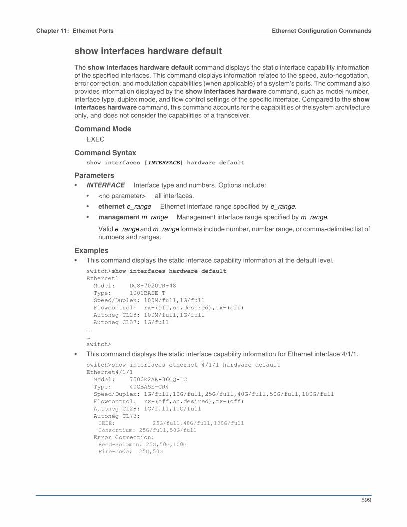
Chapter 11: Ethernet Ports Ethernet Configuration Commands
599
show interfaces hardware default
The show interfaces hardware default command displays the static interface capability informationof the specified interfaces. This command displays information related to the speed, auto-negotiation,error correction, and modulation capabilities (when applicable) of a system’s ports. The command alsoprovides information displayed by the show interfaces hardware command, such as model number,interface type, duplex mode, and flow control settings of the specific interface. Compared to the showinterfaces hardware command, this command accounts for the capabilities of the system architectureonly, and does not consider the capabilities of a transceiver.
Command ModeEXEC
Command Syntaxshow interfaces [INTERFACE] hardware default
Parameters• INTERFACE Interface type and numbers. Options include:
• <no parameter> all interfaces.
• ethernet e_range Ethernet interface range specified by e_range.
• management m_range Management interface range specified by m_range.
Valid e_range and m_range formats include number, number range, or comma-delimited list ofnumbers and ranges.
Examples• This command displays the static interface capability information at the default level.
switch>show interfaces hardware defaultEthernet1 Model: DCS-7020TR-48 Type: 1000BASE-T Speed/Duplex: 100M/full,1G/full Flowcontrol: rx-(off,on,desired),tx-(off) Autoneg CL28: 100M/full,1G/full Autoneg CL37: 1G/full……switch>
• This command displays the static interface capability information for Ethernet interface 4/1/1.
switch>show interfaces ethernet 4/1/1 hardware defaultEthernet4/1/1 Model: 7500R2AK-36CQ-LC Type: 40GBASE-CR4 Speed/Duplex: 1G/full,10G/full,25G/full,40G/full,50G/full,100G/full Flowcontrol: rx-(off,on,desired),tx-(off) Autoneg CL28: 1G/full,10G/full Autoneg CL73:
IEEE: 25G/full,40G/full,100G/fullConsortium: 25G/full,50G/full
Error Correction:Reed-Solomon: 25G,50G,100GFire-code: 25G,50G
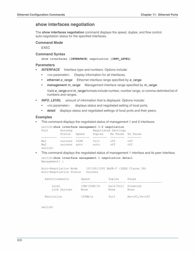
600
Ethernet Configuration Commands Chapter 11: Ethernet Ports
show interfaces negotiation
The show interfaces negotiation command displays the speed, duplex, and flow controlauto-negotiation status for the specified interfaces.
Command ModeEXEC
Command Syntaxshow interfaces [INTERFACE] negotiation [INFO_LEVEL]
Parameters• INTERFACE Interface type and numbers. Options include:
• <no parameter> Display information for all interfaces.
• ethernet e_range Ethernet interface range specified by e_range.
• management m_range Management interface range specified by m_range.
Valid e_range and m_range formats include number, number range, or comma-delimited list ofnumbers and ranges.
• INFO_LEVEL amount of information that is displayed. Options include:
• <no parameter> displays status and negotiated setting of local ports.
• detail displays status and negotiated settings of local ports and their peers.
Examples• This command displays the negotiated status of management 1 and 2 interfaces
switch>show interface management 1-2 negotiationPort Autoneg Negotiated Settings Status Speed Duplex Rx Pause Tx Pause--------- ------- -------- -------- -------- --------Ma1 success 100M full off offMa2 success auto auto off offswitch>
• This command displays the negotiated status of management 1 interface and its peer interface.
switch>show interface management 1 negotiation detailManagement1 :
Auto-Negotiation Mode 10/100/1000 BASE-T (IEEE Clause 28)Auto-Negotiation Status Success
Advertisements Speed Duplex Pause --------------- ---------- -------------------- Local 10M/100M/1G half/full Disabled Link Partner None None None
Resolution 100Mb/s full Rx=off,Tx=off
switch>
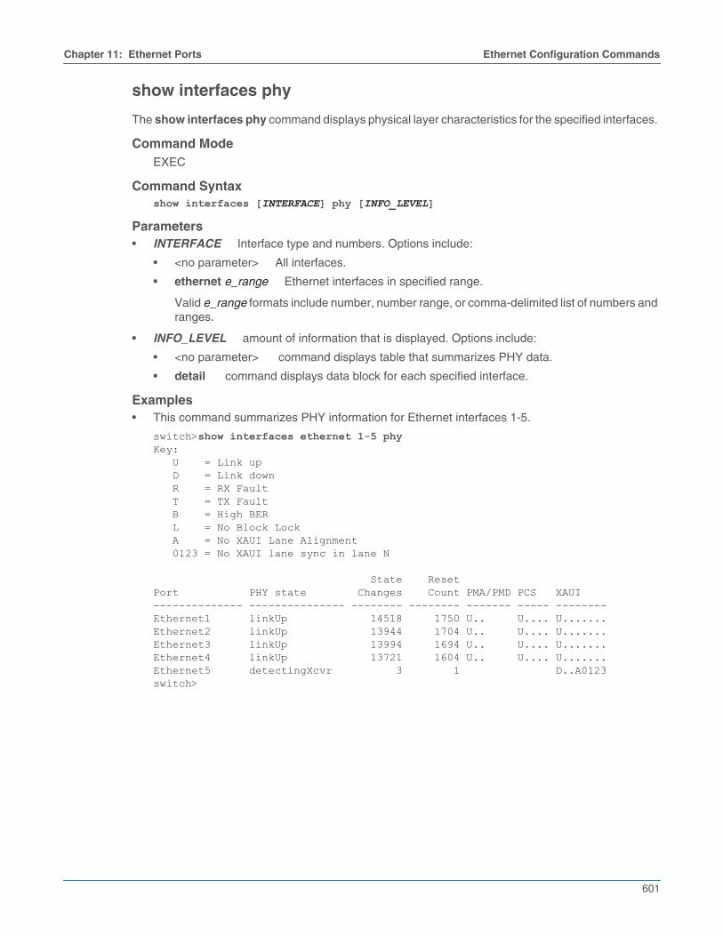
Chapter 11: Ethernet Ports Ethernet Configuration Commands
601
show interfaces phy
The show interfaces phy command displays physical layer characteristics for the specified interfaces.
Command ModeEXEC
Command Syntaxshow interfaces [INTERFACE] phy [INFO_LEVEL]
Parameters• INTERFACE Interface type and numbers. Options include:
• <no parameter> All interfaces.
• ethernet e_range Ethernet interfaces in specified range.
Valid e_range formats include number, number range, or comma-delimited list of numbers andranges.
• INFO_LEVEL amount of information that is displayed. Options include:
• <no parameter> command displays table that summarizes PHY data.
• detail command displays data block for each specified interface.
Examples• This command summarizes PHY information for Ethernet interfaces 1-5.
switch>show interfaces ethernet 1-5 phyKey: U = Link up D = Link down R = RX Fault T = TX Fault B = High BER L = No Block Lock A = No XAUI Lane Alignment 0123 = No XAUI lane sync in lane N
State ResetPort PHY state Changes Count PMA/PMD PCS XAUI-------------- --------------- -------- -------- ------- ----- --------Ethernet1 linkUp 14518 1750 U.. U.... U.......Ethernet2 linkUp 13944 1704 U.. U.... U.......Ethernet3 linkUp 13994 1694 U.. U.... U.......Ethernet4 linkUp 13721 1604 U.. U.... U.......Ethernet5 detectingXcvr 3 1 D..A0123switch>

602
Ethernet Configuration Commands Chapter 11: Ethernet Ports
• This command displays detailed PHY information for Ethernet interface 1.
switch>show interfaces ethernet 1 phy detailCurrent System Time: Mon Dec 5 11:32:57 2011Ethernet1 Current State Changes Last Change PHY state linkUp 14523 0:02:01 ago HW resets 1751 0:02:07 ago Transceiver 10GBASE-SRL 1704 0:02:06 ago Transceiver SN C743UCZUD Oper speed 10Gbps Interrupt Count 71142 Diags mode normalOperation Model ael2005c Active uC image microInit_mdio_SR_AEL2005C_28 Loopback none PMA/PMD RX signal detect ok 11497 0:37:24 ago PMA/PMD RX link status up 11756 0:37:24 ago PMA/PMD RX fault ok 11756 0:37:24 ago PMA/PMD TX fault ok 0 never PCS RX link status up 9859 0:02:03 ago PCS RX fault ok 9832 0:02:03 ago PCS TX fault ok 330 0:27:44 ago PCS block lock ok 9827 0:02:03 ago PCS high BER ok 8455 0:02:05 ago PCS err blocks 255 0:02:03 ago PCS BER 16 50092 0:02:05 ago XFI/XAUI TX link status up 1282 0:27:44 ago XFI/XAUI RX fault ok 585 0:27:44 ago XFI/XAUI TX fault ok 2142 0:02:05 ago XFI/XAUI alignment status ok 2929 0:02:05 ago XAUI lane 0-3 sync (0123) = 1111 2932 0:02:05 ago XAUI sync w/o align HWM 0 never XAUI sync w/o align max OK 5 XAUI excess sync w/o align 0 never Xcvr EEPROM read timeout 46 4 days, 6:33:45 ago Spurious xcvr detection 0 never DOM control/status fail 0 I2C snoop reset 0 I2C snoop reset (xcvr) 0 Margin count 5 last > 0 0:00:00 ago EDC resets 1 0:02:03 ago EDC FFE0 - FFE11 -4 -5 57 -6 -6 -2 1 0 -2 -1 1 -1 EDC FBE1 - FBE4 6 -1 5 -1 EDC TFBE1 - TFBE4 1 2 1 2 EDC VGA1, VGA3 12 115 TX path attenuation 3.0 dB TX preemphasis (0,63,4) (pre,main,post)switch>

Chapter 11: Ethernet Ports Ethernet Configuration Commands
603
show interfaces status
The show interfaces status command displays the interface name, link status, vlan, duplex, speed,and type of the specified interfaces. When the command includes a link status, the results are filteredto display only interfaces whose link status match the specified type.
Command ModeEXEC
Command Syntaxshow interfaces [INTERFACE] status [STATUS_TYPE]
Parameters• INTERFACE Interface type and numbers. Options include:
• <no parameter> All existing interfaces.
• ethernet e_range Ethernet interfaces in the specified range.
• management m_range Management interfaces in the specified range.
• port-channel p_range All existing port-channel interfaces in the specified range.
Valid e_range, m_range, and p_range formats include number, number range, orcomma-delimited list of numbers and ranges.
• STATUS_TYPE interface status upon which the command filters output. Options include:
• <no parameter> command does not filter on interface status.
• connected interfaces connected to another port.
• notconnect unconnected interfaces that are capable of connecting to another port.
• disabled interfaces that have been powered down or disabled.
• sub-interfaces L3 subinterfaces configured on the switch.
Command may include multiple status types (connected notconnect disabled), which canbe placed in any order.
Example• This command displays the status of Ethernet interfaces 1-5.
switch>show interfaces ethernet 1-5 statusPort Name Status Vlan Duplex Speed TypeEt1 connected 1 full 10G 10GBASE-SRLEt2 connected 1 full 10G 10GBASE-SRLEt3 connected 1 full 10G 10GBASE-SRLEt4 connected 1 full 10G 10GBASE-SRLEt5 notconnect 1 full 10G Not Presentswitch>
This command displays status information for all subinterfaces configured on the switch.
switch>show interfaces status sub-interfacesPort Name Status Vlan Duplex Speed Type FlagsEt1.1 connect 101 full 10G dot1q-encapsulationEt1.2 connect 102 full 10G dot1q-encapsulationEt1.3 connect 103 full 10G dot1q-encapsulationEt1.4 connect 103 full 10G dot1q-encapsulationswitch>

604
Ethernet Configuration Commands Chapter 11: Ethernet Ports
show interfaces status errdisabled
The show interfaces status errdisabled command displays interfaces that are in errdisabled state,including their link status and errdisable cause.
Command ModeEXEC
Command Syntaxshow interfaces [INTERFACE] status errdisabled
Parameters• INTERFACE Interface type and numbers. Options include:
• <no parameter> Display information for all interfaces.
• ethernet e_range Ethernet interface range specified by e_range.
• management m_range Management interface range specified by m_range.
• port-channel p_range Port-Channel Interface range specified by p_range.
Valid e_range and m_range formats include number, number range, or comma-delimited list ofnumbers and ranges.
Examples• This command displays the error-disabled ports.
switch>show interfaces status errdisabled Port Name Status Reason------------ ---------------- ----------------- ------------------ Et49/2 errdisabled multi-lane-intf Et49/3 errdisabled multi-lane-intf Et49/4 errdisabled multi-lane-intfswitch>

Chapter 11: Ethernet Ports Ethernet Configuration Commands
605
show interfaces transceiver
The show interfaces transceiver command displays operational transceiver data for the specifiedinterfaces.
Command ModeEXEC
Command Syntaxshow interfaces [INTERFACE] transceiver [DATA_FORMAT]
Parameters• INTERFACE Interface type and numbers. Options include:
• <no parameter> all interfaces.
• ethernet e_range Ethernet interface range specified by e_range.
• management m_range Management interface range specified by m_range.
Valid e_range, and m_range formats include number, number range, or comma-delimited listof numbers and ranges.
• DATA_FORMAT format used to display the data. Options include:
• <no parameter> table entries separated by tabs.
• csv table entries separated by commas.
Related Commands• show interfaces transceiver properties
Examples• This command displays transceiver data on Ethernet interfaces 1 through 4.
switch>show interfaces ethernet 1-4 transceiverIf device is externally calibrated, only calibrated values are printed.N/A: not applicable, Tx: transmit, Rx: receive.mA: milliamperes, dBm: decibels (milliwatts). Bias Optical Optical Temp Voltage Current Tx Power Rx Power Last UpdatePort (Celsius) (Volts) (mA) (dBm) (dBm) (Date Time)----- --------- -------- -------- -------- -------- -------------------Et1 34.17 3.30 6.75 -2.41 -2.83 2011-12-02 16:18:48Et2 35.08 3.30 6.75 -2.23 -2.06 2011-12-02 16:18:42Et3 36.72 3.30 7.20 -2.02 -2.14 2011-12-02 16:18:49Et4 35.91 3.30 6.92 -2.20 -2.23 2011-12-02 16:18:45switch>

606
Ethernet Configuration Commands Chapter 11: Ethernet Ports
show interfaces transceiver channels
The show interfaces transceiver channels command displays current wavelength/frequencysettings for the specified channels.
Command ModeEXEC
Command Syntaxshow interfaces [INTERFACE e_range] transceiver channels
Parameters• INTERFACE Interface type and port numbers.
• ethernet e_range Ethernet interface range specified by e_range.
Related Commands• transceiver channel
• show interfaces transceiver hardware
Examples• This command displays the supported wavelengths/frequencies and their corresponding channel
numbers on Ethernet interface 4 to slot 3 through 4.
switch(config-as-if-Et4/1/3)#show interfaces ethernet 4 / 3 / 4 transceiver channels Name: Et4/3/4 100GHz- 50GHz- Wavelength Frequency spacing spacing (nm) (GHz) Channel Channel ---------- --------- ------- ------- 1567.95 191,200 1 1 1567.54 191,250 2 1567.13 191,300 2 3 1566.72 191,350 4 .... 1529.16 196,050 98 1528.77 196,100 50 99 1528.38 196,150 100switch(config-as-if-Et4/1/3)#

Chapter 11: Ethernet Ports Ethernet Configuration Commands
607
show interfaces transceiver hardware
The show interfaces transceiver hardware command displays current wavelength/frequencysettings for the specified transceiver interfaces.
Command ModeEXEC
Command Syntaxshow interfaces [INTERFACE e_range] transceiver hardware
Parameters• INTERFACE Interface type and port numbers.
• ethernet e_range Ethernet interface range specified by e_range.
Related Commands• transceiver channel
• show interfaces transceiver channels
Examples• This command displays the current wavelength/frequency settings on Ethernet interface 4 to slot
3 through 4.
switch(config-as-if-Et4/1/3)#show interfaces ethernet 4 / 3 / 4 transceiver hardware Name: Et4/3/4 Media Type: 10GBASE-DWDM Configured Channel : 39 Configured Grid (GHz) : 50 Computed Frequency (GHz) : 193,100 Computed Wavelength (nm) : 1552.52 Operational Channel : 39 (Default) Operational Grid (GHz) : 50 (Default) Operational Frequency (GHz): 193,100 Operational Wavelength (nm): 1552.52switch(config-as-if-Et4/1/3)#

608
Ethernet Configuration Commands Chapter 11: Ethernet Ports
show interfaces transceiver properties
The show interfaces transceiver properties command displays configuration information for thespecified interfaces. Information provided by the command includes the media type, interfacespeed-duplex settings, speed-duplex operating state.
Command ModeEXEC
Command Syntaxshow interfaces [INTERFACE] transceiver properties
Parameters• INTERFACE Interface type and numbers. Options include:
• <no parameter> Display information for all interfaces.
• ethernet e_range Ethernet interface range specified by e_range.
• management m_range Management interface range specified by m_range.
Valid e_range and m_range formats include number, number range, or comma-delimited list ofnumbers and ranges.
Related Commands• show interfaces transceiver
Examples• This command displays the media type, speed, and duplex properties for Ethernet interfaces 1-3.
switch>show interfaces ethernet 1-3 transceiver propertiesName : Et1Administrative Speed: 10GAdministrative Duplex: fullOperational Speed: 10G (forced)Operational Duplex: full (forced)Media Type: 10GBASE-SRL
Name : Et2Administrative Speed: 10GAdministrative Duplex: fullOperational Speed: 10G (forced)Operational Duplex: full (forced)Media Type: 10GBASE-SRL
Name : Et3Administrative Speed: 10GAdministrative Duplex: fullOperational Speed: 10G (forced)Operational Duplex: full (forced)Media Type: 10GBASE-SRL
switch>

Chapter 11: Ethernet Ports Ethernet Configuration Commands
609
show monitor ethernet oam profile
The show monitor ethernet oam profile command displays configuration information for the specifiedethernet OAM profile name or the summary information of all configured profile names.
Command ModeEXEC
Command Syntaxshow monitor ethernet oam profile {name | summary}
Parameters• name The EOAM profile name.
• summary The EOAM summary of all profiles that are configured.
Related Commands• link-error
• monitor ethernet oam profile
Examples• This command displays the OAM profile configuration information for the specific profile name.
switch#show monitor ethernet oam profile [ <name> ]
Ethernet OAM Profile : p
Error Type : symbol
Threshold : 20 frames Action : log Period : 20 seconds
Error Type : fcs Threshold : 10 frames Action : linkfault Period : 100 frame
Recovery Timeout : 20
• This command displays the OAM profile configuration summary for all profiles configured.
switch>show monitor ethernet oam profile [ <name> ] summary
Eoam Profile : p Configured on: Et3/1-4,5

610
Ethernet Configuration Commands Chapter 11: Ethernet Ports
show platform fm6000 agileport map
The show platform fm6000 agileport map command displays the list of Ethernet interfaces that arecombinable to form a higher speed port.
Command ModePrivileged EXEC
Command Syntaxshow platform fm6000 agileport map
Example• These commands displays the agile port map for the switch, then configures Ethernet interface 13
as a 40G port, subsuming Ethernet interfaces 15, 17 and 19.
switch#show platform fm6000 agileport map
-----------------------------------------------------------------Agile Ports | Interfaces subsumed in 40G link-----------------------------------------------------------------Ethernet1 | Ethernet3 Ethernet5 Ethernet7Ethernet2 | Ethernet4 Ethernet6 Ethernet8Ethernet13 | Ethernet15 Ethernet17 Ethernet19Ethernet14 | Ethernet16 Ethernet18 Ethernet20switch#configswitch(config)#interface ethernet 13switch(config-if-Et13)#speed forced 40gfull
WARNING! Executing this command will cause the forwarding agent to be restarted. All interfaces will briefly drop links and forwarding on all interfaces will momentarily stop.
Do you wish to proceed with this command? [y/N]
Ethernet13 configured for 40G.Ethernet15, Ethernet17 and Ethernet19 are now subsumed.switch(config-if-Et13)#

Chapter 11: Ethernet Ports Ethernet Configuration Commands
611
show poe
The show poe command displays PoE information for a specified port range or for all ports.
Command ModePrivileged EXEC
Command Syntaxshow poe [INTERFACE]
Parameters• INTERFACE Interface type and numbers. Options include:
• <no parameter> Display information for all interfaces.
• ethernet e_range Ethernet interface range specified by e_range.
Example• This command displays PoE information for Ethernet interface 46.switch(config)#show poe interface ethernet 46show poe interface ethernet 46 PSE LLDP Power Granted PortPort Enabled Enabled Limit Power State Class Power Current Voltage Temperature---- ------- ------- ------ ------- ------- ------ ----- ------- ------- -----------46 True True 15.40W 15.40W powered class0 1.40W 27.00mA 55.04V 41.25Cswitch(config-if-Et7)#
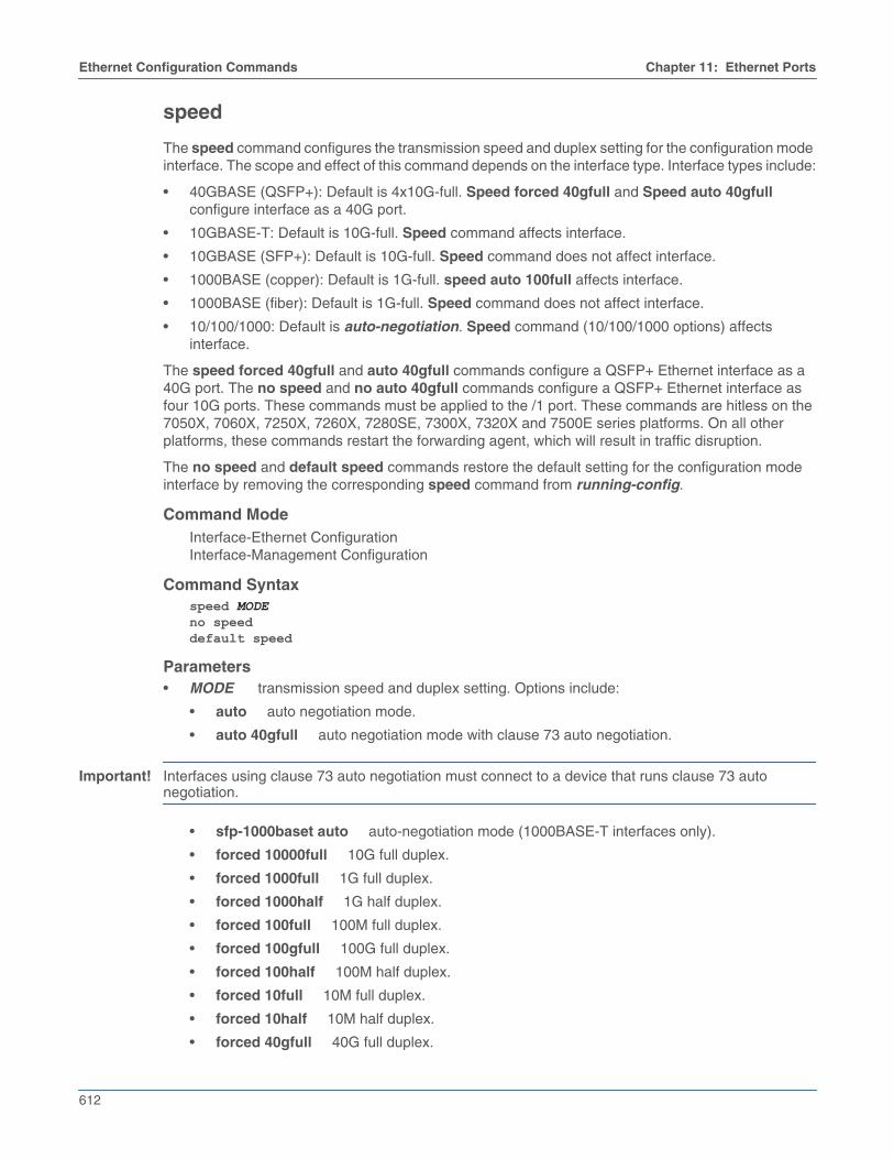
612
Ethernet Configuration Commands Chapter 11: Ethernet Ports
speed
The speed command configures the transmission speed and duplex setting for the configuration modeinterface. The scope and effect of this command depends on the interface type. Interface types include:
• 40GBASE (QSFP+): Default is 4x10G-full. Speed forced 40gfull and Speed auto 40gfullconfigure interface as a 40G port.
• 10GBASE-T: Default is 10G-full. Speed command affects interface.
• 10GBASE (SFP+): Default is 10G-full. Speed command does not affect interface.
• 1000BASE (copper): Default is 1G-full. speed auto 100full affects interface.
• 1000BASE (fiber): Default is 1G-full. Speed command does not affect interface.
• 10/100/1000: Default is auto-negotiation. Speed command (10/100/1000 options) affectsinterface.
The speed forced 40gfull and auto 40gfull commands configure a QSFP+ Ethernet interface as a40G port. The no speed and no auto 40gfull commands configure a QSFP+ Ethernet interface asfour 10G ports. These commands must be applied to the /1 port. These commands are hitless on the7050X, 7060X, 7250X, 7260X, 7280SE, 7300X, 7320X and 7500E series platforms. On all otherplatforms, these commands restart the forwarding agent, which will result in traffic disruption.
The no speed and default speed commands restore the default setting for the configuration modeinterface by removing the corresponding speed command from running-config.
Command ModeInterface-Ethernet ConfigurationInterface-Management Configuration
Command Syntaxspeed MODEno speeddefault speed
Parameters• MODE transmission speed and duplex setting. Options include:
• auto auto negotiation mode.
• auto 40gfull auto negotiation mode with clause 73 auto negotiation.
Important! Interfaces using clause 73 auto negotiation must connect to a device that runs clause 73 autonegotiation.
• sfp-1000baset auto auto-negotiation mode (1000BASE-T interfaces only).
• forced 10000full 10G full duplex.
• forced 1000full 1G full duplex.
• forced 1000half 1G half duplex.
• forced 100full 100M full duplex.
• forced 100gfull 100G full duplex.
• forced 100half 100M half duplex.
• forced 10full 10M full duplex.
• forced 10half 10M half duplex.
• forced 40gfull 40G full duplex.

Chapter 11: Ethernet Ports Ethernet Configuration Commands
613
On 40GBASE and 100GBASE interfaces, options that change the SFP+ and MXP interfaces (the auto40gfull, the forced 40gfull, and the no speed options) may restart the forwarding agent on someswitch platforms, disrupting traffic on all ports for more than a minute.
Examples• This command configures a 40GBASE interface as a 40G port.
switch(config)#interface ethernet 49/1switch(config-if-Et49/1)#speed forced 40gfullswitch(config-if-Et49/1)#show interface ethernet 49/1 - 49/4 statusPort Name Status Vlan Duplex Speed TypeEt49/1 connected in Po999 full 40G 40GBASE-CR4Et49/2 errdisabled inactive unconf unconf 40GBASE-CR4Et49/3 errdisabled inactive unconf unconf 40GBASE-CR4Et49/4 errdisabled inactive unconf unconf 40GBASE-CR4switch(config-if-Et49/1)#
• This command configures a 40GBASE interface as four 10G ports (default configuration).
switch(config-if-Et49/1)#no speedswitch(config-if-Et49/1)#show interface ethernet 49/1 - 49/4 statusPort Name Status Vlan Duplex Speed TypeEt49/1 connected routed full 10G 40GBASE-SR4Et49/2 connected routed full 10G 40GBASE-SR4Et49/3 connected routed full 10G 40GBASE-SR4Et49/4 notconnect inactive full 10G 40GBASE-SR4switch(config-if-Et49/1)#

614
Ethernet Configuration Commands Chapter 11: Ethernet Ports
threshold
The threshold command configures the link monitoring threshold value that is specified for a link error.
The no threshold and the default threshold commands remove the threshold value specified for thechosen link error.
Command ModeLink-error Configuration
Command Syntax{fcs | symbol} threshold threshold_valueno {fcs | symbol} threshold threshold_valuedefault {fcs | symbol} threshold threshold_value
Parameters• fcs Inbound packets with frame check sequence (FCS) error.
• symbol Inbound packets with symbol error.
• threshold_value Specifies the threshold value in number of errors. The value ranges from 1 to100.
Related Commands• action
• period
Example• These commands set the threshold value of 20 for the profile profile1 in the Link-error configuration
mode.
switch(config)#monitor ethernet oamswitch(config-eoam)#profile profile1switch(config-eoam-profile-profile1)#link-errorswitch(config-eoam-profile-profile1-link-error)#symbol threshold 20

Chapter 11: Ethernet Ports Ethernet Configuration Commands
615
transceiver qsfp default-mode
The transceiver qsfp default-mode command specifies the transmission mode of all QSFPtransceiver modules that are not explicitly configured.
Each QSFP+ module Ethernet interface is configurable as a single 40G port or as four 10G ports. Theswitch displays four ports for each interface. Each port’s status depends on the interface configuration:
• The /1 port is active (connected or not connected), regardless of the interface configuration.
• The /2, /3, and /4 ports are error-disabled when the interface is configured as a single 40G port.
• all ports are active (connected or not connected), when the interface is configured as four 10Gports.
The only available default-mode value is 4x10G; QSFP modules that are not configured through aspeed command are operated as four 10G ports.
The no transceiver qsfp default-mode and default transceiver qsfp default-mode commandsrestore the default-mode transceiver setting to its default value of 4x10G.
Command ModeGlobal Configuration
Command Syntaxtransceiver qsfp default-mode 4x10Gno transceiver qsfp default-modedefault transceiver qsfp default-mode
GuidelinesThe transceiver qsfp default-mode 4x10g statement is always in running-config and cannot bemodified or removed in the current release.

616
Ethernet Configuration Commands Chapter 11: Ethernet Ports
transceiver channel
The transceiver channel command displays transceiver wavelength/frequency by channel number.The channel numbering depends on the selected grid-spacing mode. The default grid-spacing modeis 50GHz-spacing.
• If the startup configuration does not specify the channel number for the interface, the transceiverwill automatically tune to the default channel (i.e. channel-39 of 50GHz-spacing grid) when it isinserted.
• If the configured wavelength/frequency is not supported by the transceiver, the transceiver will betuned to the default channel (i.e. channel-39 of 50GHz-spacing grid).
The interface is shutdown before the channel number is configured.
Command ModeGlobal Configuration
Command Syntaxtransceiver channel CHANNEL_NUMBER grid-spacing <SPACING_GRID>no transceiver channel CHANNEL_NUMBER [GRID_SPACING <SPACING_GRID>default transceiver channel CHANNEL_NUMBER [GRID_SPACING <SPACING_GRID>
Parameters• CHANNEL-NUMBER The default channel is 39 (50GHz-spacing grid) which corresponds to a
frequency of 193,100 GHz and a wavelength of 1552.52 nm.
• GRID_SPACING Grid-spacing mode (optional) depends on the selected grid-spacing mode.The default grid-spacing mode is 50GHz-spacing. For example, channel 39 of 50GHz-spacing gridis equivalent to channel 20 of 100GHz-spacing grid, which corresponds to a frequency of 193,100GHz and a wavelength of 1552.52 nm.
• <SPACING_GRID> default grid-spacing mode in GHz.
Related Commands• show interfaces transceiver channels
• show interfaces transceiver hardware
Example• This command tunes the transceiver on slot number 4 to slot 1 through 3 of 50GHz-spacing grid.
switch(config-as)#interface ethernet 4 / 1 / 3switch(config-if-Et4/1/3)#transceiver channel 1 grid-spacing 50switch(config-if-Et4/1/3)#