chapter 11 – structures table of contents · chapter 11 – structures table of contents ... a....
TRANSCRIPT

CHAPTER 11 – STRUCTURES
TABLE OF CONTENTS
Section Title Page
11.1 General ....................................................................................................................... 11-1
11.1.1 Design Standards .......................................................................................................................11-1 A. List of Structural Standards to be Followed .........................................................................11-1
11.1.2 Borings and Soils Tests..............................................................................................................11-1 11.1.3 Design Approaches ....................................................................................................................11-1
A. Working Stress Design (WSD).............................................................................................11-1 B. Load Factor Design (LFD) ...................................................................................................11-1 C. Load and Resistance Factor Design (LRFD) ........................................................................11-2 D. AASHTO Approaches..........................................................................................................11-2
11.1.4 Deflection Control......................................................................................................................11-2
11.2 Bridges ....................................................................................................................... 11-2
11.2.1 General .......................................................................................................................................11-2 11.2.2 Sufficiency Rating......................................................................................................................11-2 11.2.3 Definition and Types of Bridges ...............................................................................................11-2
A. Basic Construction Parameters .............................................................................................11-2 B. Span Construction Types......................................................................................................11-3
11.2.4 Vehicular Bridges ......................................................................................................................11-3 A. Illumination ..........................................................................................................................11-3 B. Design Loads ........................................................................................................................11-3 C. Design Details ......................................................................................................................11-3 D. Clear Width ..........................................................................................................................11-4 E. Sidewalks..............................................................................................................................11-4 F. Median Barriers ....................................................................................................................11-4
11.2.5 Pedestrian/Bicycle Bridges (P/B Bridges) ................................................................................11-4 A. Design Approach ..................................................................................................................11-4 B. Design Loads ........................................................................................................................11-4 C. Wind .....................................................................................................................................11-5 D. Design Details ......................................................................................................................11-5
11.3 Railings....................................................................................................................... 11-6
11.3.1 General .......................................................................................................................................11-6 A. Purpose .................................................................................................................................11-6 B. Using Rigid Railings ............................................................................................................11-6 C. Compliance with Standard Drawings ...................................................................................11-6
11.3.2 Traffic Railing............................................................................................................................11-6 A. Bridge Railing ......................................................................................................................11-6 B. Roadside Barrier ...................................................................................................................11-8
11.3.3 Pedestrian Railing......................................................................................................................11-9 A. Placement .............................................................................................................................11-9 B. Construction Materials .........................................................................................................11-9 C. Design Loads ........................................................................................................................11-9
11.3.4 Bicycle Railing..........................................................................................................................11-10 A. Placement ...........................................................................................................................11-10 B. Construction Materials .......................................................................................................11-10 C. Design Loads ......................................................................................................................11-10
11.3.5 Combination Pedestrian, Vehicle and/or Bicycle Traffic Barrier .......................................11-10 A. Conditions for Use..............................................................................................................11-10 B. Placement ...........................................................................................................................11-10
11.4 Retaining Walls and Abutments............................................................................. 11-10
Larimer County Urban Area Street Standards – Repealed and Reenacted April 1, 2007 Page 11-i Adopted by Larimer County, City of Loveland, City of Fort Collins
11.4.1 General ..................................................................................................................................... 11-10 A. Description ......................................................................................................................... 11-10 B. Backfill Materials............................................................................................................... 11-11 C. Drainage ............................................................................................................................. 11-11 D. Design Life......................................................................................................................... 11-11
11.4.2 Conventional Retaining Walls and Abutments..................................................................... 11-11 A. Avoid Placement in Right-of-way...................................................................................... 11-11 B. Requirements When Beyond Right-of-way ....................................................................... 11-11 C. Loading .............................................................................................................................. 11-11
11.4.3 Anchored Walls ....................................................................................................................... 11-12 A. Loading .............................................................................................................................. 11-12
11.4.4 Mechanically Stabilized Earth Walls (MSEW) .................................................................... 11-12 A. Loading .............................................................................................................................. 11-12 B. Application for MSEW ...................................................................................................... 11-12 C. Unacceptable Uses of MSEW ............................................................................................ 11-12
11.4.5 Prefabricated Modular Walls................................................................................................. 11-12 A. Loading .............................................................................................................................. 11-12 B. Application for Prefabricated Modular Wall...................................................................... 11-13 C. Unacceptable Uses of Prefabricated Modular Wall ........................................................... 11-13
11.4.6 Placement of Walls .................................................................................................................. 11-13 A. Relationship to Shoulder .................................................................................................... 11-13 B. Retaining Wall at Roadway Level ..................................................................................... 11-13
11.5 Buried Structures .................................................................................................... 11-13
11.5.1 Design Life. .............................................................................................................................. 11-13 11.5.2 Design Loads............................................................................................................................ 11-13
A. Non-Vehicular Loads ......................................................................................................... 11-13 B. Vehicular Loads ................................................................................................................. 11-14 C. Tolerable Movement .......................................................................................................... 11-14 D. Embankment Installation.................................................................................................... 11-14 E. Minimum Soil Cover.......................................................................................................... 11-14 F. Minimum Pipe Spacing...................................................................................................... 11-15
11.5.3 Structural Plate Box Structures ............................................................................................. 11-16 A. Design ................................................................................................................................ 11-16 B. Geometric Requirements.................................................................................................... 11-16 C. Embankment Installation.................................................................................................... 11-16 D. Live Loads.......................................................................................................................... 11-17 E. Maximum Soil Cover......................................................................................................... 11-17 F. Concrete Relieving Slabs ................................................................................................... 11-17
11.5.4 Reinforced Concrete Pipe ....................................................................................................... 11-17 A. Design ................................................................................................................................ 11-17 B. Trench and Embankment Installations ............................................................................... 11-17 C. Live Loads.......................................................................................................................... 11-18
11.5.5 Reinforced Concrete Cast-in-Place, Precast Box Culverts, and Reinforced Cast-in-Place
Arches....................................................................................................................................... 11-18 A. Trench and Embankment Installations ............................................................................... 11-18 B. Other Installations .............................................................................................................. 11-18 C. Live Loads.......................................................................................................................... 11-18 D. Crack Width Control .......................................................................................................... 11-19
11.5.6 Thermoplastic Pipe ................................................................................................................. 11-19 A. Design ................................................................................................................................ 11-19 B. Localized Distortion........................................................................................................... 11-19 C. Temporary Roadways ........................................................................................................ 11-19
11.5.7 Precast Reinforced Concrete Three-sided Structures.......................................................... 11-19 A. Design ................................................................................................................................ 11-19 B. Geometric Requirements.................................................................................................... 11-20
Page 11-ii Larimer County Urban Area Street Standards – Repealed and Reenacted April 1, 2007
Adopted by Larimer County, City of Loveland, City of Fort Collins

C. Shear Key ...........................................................................................................................11-20 D. Minimum Reinforcement ...................................................................................................11-20 E. Deflection Control ..............................................................................................................11-20
LIST OF TABLES
Table 11-1 Bridge Span Types .................................................................................................................................11-3 Table 11-2 H-Truck Loading ...................................................................................................................................11-5 Table 11-3 Design Wind Load .................................................................................................................................11-5 Table 11-4 Roadside Barriers...................................................................................................................................11-8 Table 11-5 Suggested Shy Line Offset (Ls) Values..................................................................................................11-9 Table 11-6 Minimum Width of Soil Envelopes .....................................................................................................11-14 Table 11-7 Minimum Soil Cover for Buried Structures.........................................................................................11-15 Table 11-8 Minimum Soil Cover for Buried Long Span Plate Pipe Structures......................................................11-15 Table 11-9 Minimum Pipe Spacing........................................................................................................................11-16 Table 11-10 Geometric Requirements For Structural Plate Boxes.........................................................................11-16 Table 11-11 Coefficients for Use with Figure 11-7................................................................................................11-18
LIST OF FIGURES
Figures are Located at End of Chapter
Figure 11-1 Recommended Barrier Placement
Figure 11-2 Recommended Barrier Placement
Figure 11-3 Pedestrian Railing Loads
Figure 11-4 Bicycle Railing Loads
Figure 11-5 Combination Vehicle, Pedestrian, Bicycle Barrier
Figure 11-6 Structural Plate Box Geometric Requirements
Figure 11-7 Heger Pressure Distribution & Arching Factors
Figure 11-8 Bridge Railing/Parapet Wall Configuration Detail
Larimer County Urban Area Street Standards – Repealed and Reenacted April 1, 2007 Page 11-iii Adopted by Larimer County, City of Loveland, City of Fort Collins

Chapter 11 – Structures Section 11.1 General
CHAPTER 11 – STRUCTURES
11.1 GENERAL
This chapter provides design guidelines for structures in public rights-of-way for new streets. All
designs shall be stamped by a registered PE proficient in structural engineering.
11.1.1 Design Standards
Designs of structures shall conform to these Standards and supplemented by the
following documents
A. List of Structural Standards to be Followed
1. AASHTO, Standard Specifications for Highway Bridges, latest edition.
2. AASHTO, LRFD Bridge Design Specifications, latest edition.
3. AASHTO, LRFD Bridge Construction Specifications, latest edition.
4. AASHTO, A policy on Geometric Design of Highways and Streets, 1990 edition.
5. AASHTO, Roadside Design Guide, latest edition.
6. CDOT, Bridge Manual, Volumes I and II, latest editions.
7. CDOT, Standard Specifications for Road and Bridge Construction, latest edition.
8. CDOT, M&S Standards, latest edition.
11.1.2 Borings and Soils Tests
Appropriate borings and soils tests shall be conducted as outlined in Chapter 5, Soils
Investigations.
11.1.3 Design Approaches
Recognized design approaches for structures in this chapter are as follows:
A. Working Stress Design (WSD)
WSD establishes allowable stresses as a fraction or percentage of a given material’s
load-carrying capacity. Calculated design stresses must not exceed those allowable
stresses.
B. Load Factor Design (LFD)
LFD adjusts WSD to reflect various loads such as vehicular and wind forces. This
design philosophy employs a limited use of load variability.
Larimer County Urban Area Street Standards – Repealed and Reenacted April 1, 2007 Page 11-1 Adopted by Larimer County, City of Loveland, City of Fort Collins

Chapter 11 – Structures Section 11.2 Bridges
C. Load and Resistance Factor Design (LRFD)
LRFD enlists both load and resistance factors, derived from the theory of reliability,
statistical knowledge of loads, and structural performance. This design philosophy
employs explicit use of load variability.
D. AASHTO Approaches
Either of the following AASHTO standards may be used to design structures in this
chapter unless otherwise specified:
1. AASHTO’s Standard Specifications for Highway Bridges uses the WSD and LFD
design philosophies.
2. AASHTO’s LRFD Bridge Design and Construction Specifications uses the LRFD
design philosophy.
11.1.4 Deflection Control
Designs of all three-sided concrete structures in this chapter must include deflection
control.
11.2 BRIDGES
11.2.1 General
Bridges shall be considered structures with the span between supports greater than 20
feet.
Design Life. All bridges shall have a minimum design life of 50 years.
11.2.2 Sufficiency Rating
The design of all major structures (span 20 feet) shall be rated for structural sufficiency
prior to approval of the Local Entity of the public improvement plans. The design shall
be in compliance with Federal Bridge Rating Guidelines for new bridges. Refer to
Chapter 23, Street Inspection and Testing Procedures, for further information
regarding inspection and rating.
11.2.3 Definition and Types of Bridges
Bridges can be designed to carry various load combinations. This section covers both
vehicular and pedestrian/bicycle bridges.
A. Basic Construction Parameters
Bridges shall be constructed of reinforced concrete or, where conditions prevent the
use of reinforced concrete, steel. Bridge construction of timber is prohibited unless
specifically allowed by the Local Entity Engineer.
Page 11-2 Larimer County Urban Area Street Standards – Repealed and Reenacted April 1, 2007
Adopted by Larimer County, City of Loveland, City of Fort Collins
Chapter 11 – Structures Section 11.2 Bridges
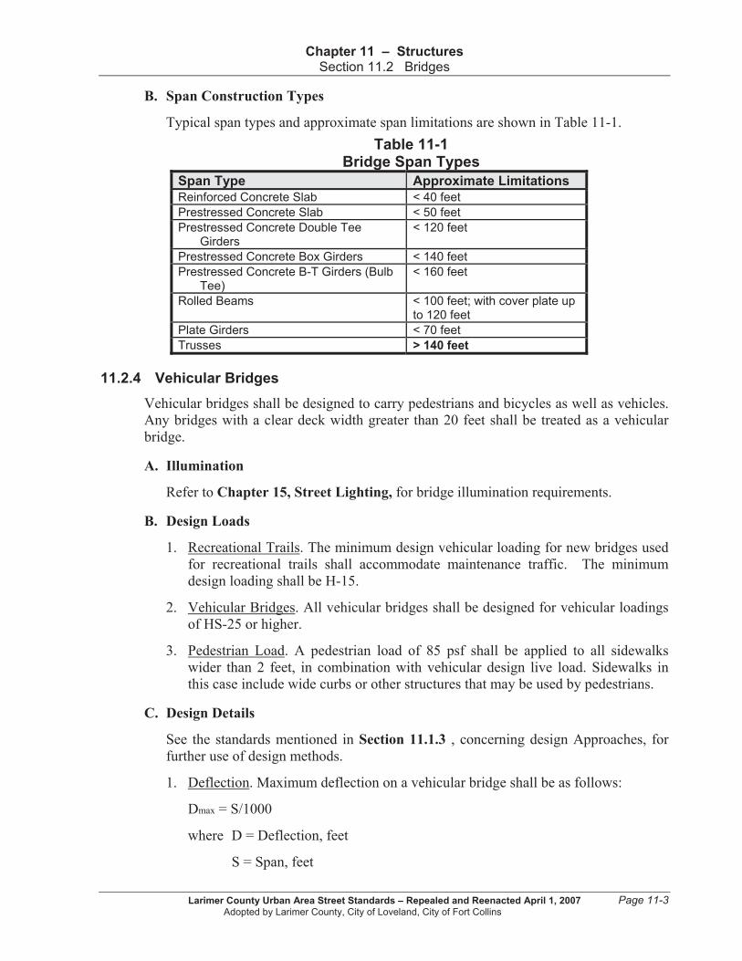
B. Span Construction Types
Typical span types and approximate span limitations are shown in Table 11-1.
Table 11-1 Bridge Span Types
Span Type Approximate Limitations
Reinforced Concrete Slab < 40 feet
Prestressed Concrete Slab < 50 feet
Prestressed Concrete Double Tee Girders
< 120 feet
Prestressed Concrete Box Girders < 140 feet
Prestressed Concrete B-T Girders (Bulb Tee)
< 160 feet
Rolled Beams < 100 feet; with cover plate up to 120 feet
Plate Girders < 70 feet
Trusses > 140 feet
11.2.4 Vehicular Bridges
Vehicular bridges shall be designed to carry pedestrians and bicycles as well as vehicles.
Any bridges with a clear deck width greater than 20 feet shall be treated as a vehicular
bridge.
A. Illumination
Refer to Chapter 15, Street Lighting, for bridge illumination requirements.
B. Design Loads
1. Recreational Trails. The minimum design vehicular loading for new bridges used
for recreational trails shall accommodate maintenance traffic. The minimum
design loading shall be H-15.
2. Vehicular Bridges. All vehicular bridges shall be designed for vehicular loadings
of HS-25 or higher.
3. Pedestrian Load. A pedestrian load of 85 psf shall be applied to all sidewalks
wider than 2 feet, in combination with vehicular design live load. Sidewalks in
this case include wide curbs or other structures that may be used by pedestrians.
C. Design Details
See the standards mentioned in Section 11.1.3 , concerning design Approaches, for
further use of design methods.
1. Deflection. Maximum deflection on a vehicular bridge shall be as follows:
Dmax = S/1000
where D = Deflection, feet
S = Span, feet
Larimer County Urban Area Street Standards – Repealed and Reenacted April 1, 2007 Page 11-3 Adopted by Larimer County, City of Loveland, City of Fort Collins

Chapter 11 – Structures Section 11.2 Bridges
2. Minimum Thickness of Metal. Closed structural tubular members shall have a
thickness of at least 5/16 inch.
D. Clear Width
The clear width for new bridges on all streets with curbed approaches shall meet or
exceed the curb-to-curb width of the roadway approaches. For streets with shoulders
and no curbs, the clear roadway width should be the same as the approach roadway
width.
E. Sidewalks
Requirements for sidewalks on bridges are as follows:
1. General. Sidewalks conforming to the street cross sections shall be provided on
both sides of a bridge.
2. Width of Parkways. Parkways are not required on the bridge structure in
Loveland (GMA and city limits).
3. Extending Approaches. Sidewalks on the approaches shall extend across all
bridges.
4. Width Criteria. Refer to sidewalk and bike path width criteria in Chapter 16,
Pedestrian Facilities, and Chapter 17, Bicycle Facilities.
5. Exceptions. Sidewalks and/or bike lanes may be omitted from a bridge when
separate bike/pedestrian bridges exist and when approved by the Engineer.
F. Median Barriers
Median barriers shall not be used in an urban setting with design speeds less than 45
mph.
11.2.5 Pedestrian/Bicycle Bridges (P/B Bridges)
P/B bridges are designed to carry primarily pedestrian and/or bicycle traffic as well as the
occasional maintenance or service vehicle. This type of bridge will not carry a vehicular
roadway.
A. Design Approach
P/B bridges shall be designed with the LFD method as provided by AASHTO
Standard Specifications for Highway Bridges.
B. Design Loads
1. Vehicular. The minimum design vehicular loading for a P/B bridge follows the H-
truck configuration loading. Specific H-truck loading depends upon clear deck
width as follows:
Page 11-4 Larimer County Urban Area Street Standards – Repealed and Reenacted April 1, 2007
Adopted by Larimer County, City of Loveland, City of Fort Collins
Chapter 11 – Structures Section 11.2 Bridges
Table 11-2 H-Truck Loading
P/B Bridge Width H-Truck Loading
6 – 10 feet H-5 truck configuration (10,000 lb)
> 10 feet H-10 truck configuration (20,000 lb)
< 6 feet Not wide enough for any vehicles
2. Pedestrian. Do not design for a combination of pedestrian and vehicular loads.
Design live loads shall be as follows:
a. Main Member. The design pedestrian live load for the Main Member shall be
85 psf, with the following exception: if the deck influence area, A1, is greater
than 400 square feet, a reduction may be made per the following equation:
Pedestrian live load = 85(0.25 + (15/square root of A1)) psf.
At no time shall the pedestrian live load be less than 65 psf.
b. Secondary Member. The design live load for the Secondary Member shall be
85 psf.
c. Deck Loading for Horses or Snowmobiles. Use a concentrated load of P =
1000 lb when horse or snowmobile traffic is present.
C. Wind
1. Wind Design Factors. Wind load is a horizontal load. There is no required
combination of wind on live loads (pedestrian or vehicular). For wind overturning
force see Section 3.15.3 of AASHTO Standard Specifications for Highway
Bridges.
2. Specific Load Criteria. The design wind load applied to the vertical area of P/B
bridge members shall be as follows:
Table 11-3 Design Wind Load
Member Type Design Wind Load
Truss and Arches 75 psf
Girders and Beams 50 psf
Open Truss 35 psf
D. Design Details
1. Deflection. Maximum deflection on a P/B bridge shall be as follows:
Dmax = S/1000
where D = Deflection, feet
S = Span, feet
2. Vibrations. Design frequencies shall be as follows:
Larimer County Urban Area Street Standards – Repealed and Reenacted April 1, 2007 Page 11-5 Adopted by Larimer County, City of Loveland, City of Fort Collins

Chapter 11 – Structures Section 11.3 Railings
a. P/B Bridge Without Live Load. When the P/B bridge has no vehicular or
pedestrian traffic, the frequency shall be greater than 3 Hz to avoid the first
harmonic.
b. P/B Bridge With Live Load. When the P/B bridge has a live load, (e.g.,
running and jumping), the frequency shall be greater than 5 Hz to avoid the
second harmonic.
3. Allowable Fatigue Stress. Fatigue provisions are not required for pedestrian live
load stresses where heavy pedestrian loads are infrequent. Fatigue provisions shall
be included for wind loads.
4. Minimum Thickness of Metal. Closed structural tubular members shall have a
thickness of at least 1/4 inch.
5. Half Through Truss Spans. Half through truss spans shall be designed per
AASHTO Guide Specifications, For Design of Pedestrian Bridges, 1997.
11.3 RAILINGS
11.3.1 General
A. Purpose
Railings offer protection to pedestrians, bicyclists, and motorists. They can be
designed to retain and redirect vehicles upon impact or to prevent rollover with high
center of gravity vehicles. Railings provide a transition from a roadway or
pedestrian/bicycle way to a bridge.
B. Using Rigid Railings
Railing systems can be rigid, or they can allow deflection to reduce penetration.
Highway structures normally warrant the use of a rigid railing.
C. Compliance with Standard Drawings
This section provides criteria for roadside/bridge, pedestrian, bicycle, and
combination barriers. Railings shall comply with Figure 11-8.
11.3.2 Traffic Railing
A traffic railing is used for roadway traffic when there is a hazard within the clear zone. It
is also used to separate the travel lane from an attached sidewalk in cases where there is
no bike lane and the posted speed is greater than or equal to 40 mph. Two types of traffic
railing are the bridge railing and the roadside barrier.
A. Bridge Railing
Bridge railings must handle vehicles on the bridge under impact conditions. Vehicles
and impact conditions are specified in the design. The railing systems listed are used
on bridge structures and appear in ascending order of strength or rigidity.
Page 11-6 Larimer County Urban Area Street Standards – Repealed and Reenacted April 1, 2007
Adopted by Larimer County, City of Loveland, City of Fort Collins

Chapter 11 – Structures Section 11.3 Railings
1. Fort Collins (GMA and city limits). All bridge railings for Fort Collins (GMA and
city limits) shall conform to Figure 11-8.
2. Loveland (GMA and city limits). Bridge railing options for Loveland (GMA and
city limits) are given in the referenced construction drawings below.
3. Types of Railings (Crash-Tested).
a. Oklahoma Modified TR-1 Bridge Railing. This rigid concrete post and beam
system reduces snow accumulation to the bridge deck. See Construction
Drawing 1102L.
b. BR1 Type C Aluminum Bridge Railing. This metal railing/concrete parapet
system has significant strength. It can redirect cars and vans but is not
adequate to prevent rollover with high center of gravity vehicles. See
Construction Drawing 1107.
c. Safety-Shaped Concrete Bridge Railing. This common bridge railing can
redirect heavy trucks and buses. See Construction Drawing 1103L.
d. Nevada Concrete Safety Shape (With Steel Rail). This railing is a raised
height system that can contain and redirect a 18,000 kg bus. See Construction
Drawing 1104L.
e. Texas Type HT (Heavy Truck). This railing can contain and redirect heavy
vehicles. See Construction Drawing 1105L.
f. Texas Type TT (Tank Truck). This extremely strong barrier railing can
contain and redirect heavy vehicles. It is very heavily reinforced and rarely
used. See Construction Drawing 1106L.
4. Using Other Types of Railing. Other railing may be proposed for review and
approval by the Local Entity. Structural calculations or crash test results need to
be submitted with such proposals.
5. Transitions. Transitions shall be provided when a semi-rigid roadside guard rail
meets a rigid bridge railing.
a. Gradual Stiffening. The transition shall provide a gradual stiffening of the
approach by adjusting the post spacing or rail strength or by transitioning to a
different, stiffer barrier.
b. Flexible Bridge Railings. Transitions may not be necessary when bridge
railings have some flexibility. Any design without a transition shall satisfy
AASHTO criteria referenced in Section 11.1.1 .
c. Alternatives in Congested Areas. In urban areas or where city streets and/or
sidewalks prevent installation of approach guardrail transitions, one or more
of the following alternatives shall be followed:
Larimer County Urban Area Street Standards – Repealed and Reenacted April 1, 2007 Page 11-7 Adopted by Larimer County, City of Loveland, City of Fort Collins
Chapter 11 – Structures Section 11.3 Railings
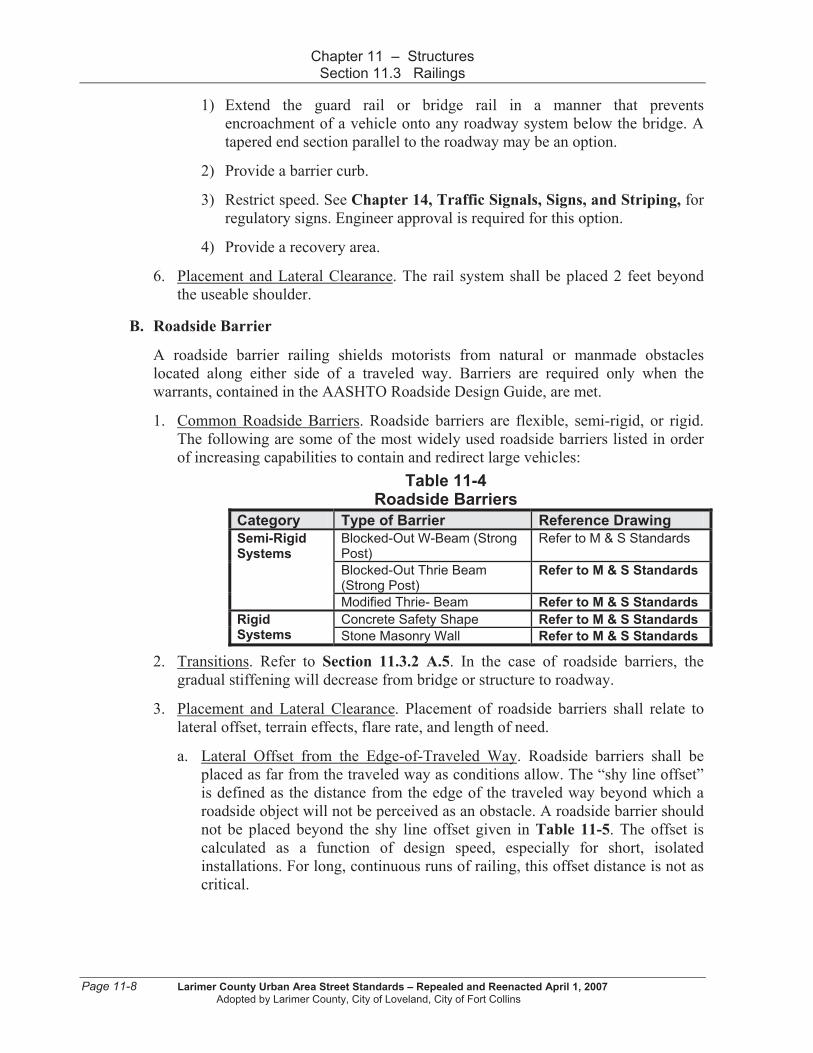
1) Extend the guard rail or bridge rail in a manner that prevents
encroachment of a vehicle onto any roadway system below the bridge. A
tapered end section parallel to the roadway may be an option.
2) Provide a barrier curb.
3) Restrict speed. See Chapter 14, Traffic Signals, Signs, and Striping, for
regulatory signs. Engineer approval is required for this option.
4) Provide a recovery area.
6. Placement and Lateral Clearance. The rail system shall be placed 2 feet beyond
the useable shoulder.
B. Roadside Barrier
A roadside barrier railing shields motorists from natural or manmade obstacles
located along either side of a traveled way. Barriers are required only when the
warrants, contained in the AASHTO Roadside Design Guide, are met.
1. Common Roadside Barriers. Roadside barriers are flexible, semi-rigid, or rigid.
The following are some of the most widely used roadside barriers listed in order
of increasing capabilities to contain and redirect large vehicles:
Table 11-4 Roadside Barriers
Category Type of Barrier Reference Drawing
Blocked-Out W-Beam (Strong Post)
Refer to M & S Standards
Blocked-Out Thrie Beam (Strong Post)
Refer to M & S Standards
Semi-Rigid Systems
Modified Thrie- Beam Refer to M & S Standards
Concrete Safety Shape Refer to M & S Standards Rigid Systems Stone Masonry Wall Refer to M & S Standards
2. Transitions. Refer to Section 11.3.2 A.5. In the case of roadside barriers, the
gradual stiffening will decrease from bridge or structure to roadway.
3. Placement and Lateral Clearance. Placement of roadside barriers shall relate to
lateral offset, terrain effects, flare rate, and length of need.
a. Lateral Offset from the Edge-of-Traveled Way. Roadside barriers shall be
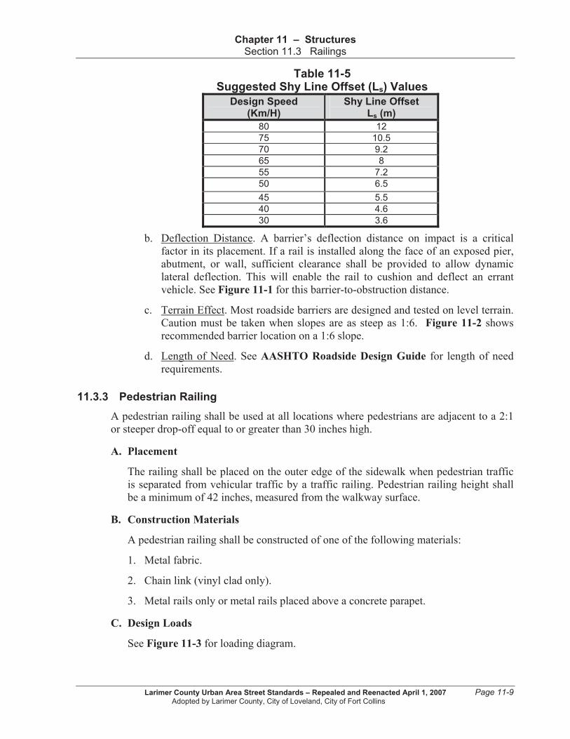
placed as far from the traveled way as conditions allow. The “shy line offset”
is defined as the distance from the edge of the traveled way beyond which a
roadside object will not be perceived as an obstacle. A roadside barrier should
not be placed beyond the shy line offset given in Table 11-5. The offset is
calculated as a function of design speed, especially for short, isolated
installations. For long, continuous runs of railing, this offset distance is not as
critical.
Page 11-8 Larimer County Urban Area Street Standards – Repealed and Reenacted April 1, 2007
Adopted by Larimer County, City of Loveland, City of Fort Collins
Chapter 11 – Structures Section 11.3 Railings
Table 11-5 Suggested Shy Line Offset (Ls) Values
Design Speed (Km/H)
Shy Line Offset Ls (m)
80 12
75 10.5
70 9.2
65 8
55 7.2
50 6.5
45 5.5
40 4.6
30 3.6
b. Deflection Distance. A barrier’s deflection distance on impact is a critical
factor in its placement. If a rail is installed along the face of an exposed pier,
abutment, or wall, sufficient clearance shall be provided to allow dynamic
lateral deflection. This will enable the rail to cushion and deflect an errant
vehicle. See Figure 11-1 for this barrier-to-obstruction distance.
c. Terrain Effect. Most roadside barriers are designed and tested on level terrain.
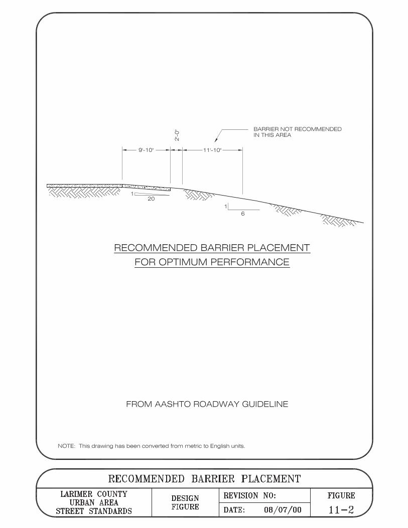
Caution must be taken when slopes are as steep as 1:6. Figure 11-2 shows
recommended barrier location on a 1:6 slope.
d. Length of Need. See AASHTO Roadside Design Guide for length of need
requirements.
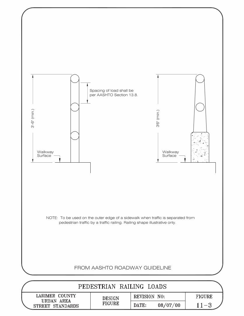
11.3.3 Pedestrian Railing
A pedestrian railing shall be used at all locations where pedestrians are adjacent to a 2:1
or steeper drop-off equal to or greater than 30 inches high.
A. Placement
The railing shall be placed on the outer edge of the sidewalk when pedestrian traffic
is separated from vehicular traffic by a traffic railing. Pedestrian railing height shall
be a minimum of 42 inches, measured from the walkway surface.
B. Construction Materials
A pedestrian railing shall be constructed of one of the following materials:
1. Metal fabric.
2. Chain link (vinyl clad only).
3. Metal rails only or metal rails placed above a concrete parapet.
C. Design Loads
See Figure 11-3 for loading diagram.
Larimer County Urban Area Street Standards – Repealed and Reenacted April 1, 2007 Page 11-9 Adopted by Larimer County, City of Loveland, City of Fort Collins

Chapter 11 – Structures Section 11.4 Retaining Walls and Abutments
1. Metal Rail Design. The design live loading shall be w = 0.050 KLF, both
transversely and vertically, acting simultaneously on each longitudinal element. A
concentrated load of 0.20 KIPS, acting on the top rail, and simultaneous with the
design live loading can be considered at any point and in any direction.
2. Chain Link/Metal Fabric Design. The design live load shall be 0.015 KSF acting
normal to the entire surface.
11.3.4 Bicycle Railing
A bicycle railing shall be used wherever bicycle lanes are adjacent to the edge of a bridge
or hazard. The railing shall be warranted when the street has designated bike lanes.
A. Placement
The bicycle railing shall be placed on the outer edge of the bike lane. Bicycle railing
height shall be a minimum of 54 inches, measured from the riding surface.
B. Construction Materials
A bicycle railing shall be constructed of metal rails only, metal rails above a concrete
parapet, chain link, or metal fabric.
C. Design Loads
See Figure 11-4 for loading diagram. Design loads are the same as for pedestrian
railing in Section 11.3.3 C.
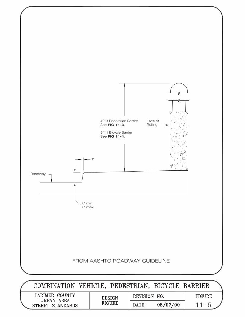
11.3.5 Combination Pedestrian, Vehicle and/or Bicycle Traffic Barrier
A. Conditions for Use
The combination barrier shall be provided whenever a raised curb and an attached
sidewalk exist adjacent to a roadway.
B. Placement
The combination barrier shall be installed adjacent to the roadway with either a
pedestrian or bicycle railing, as appropriate. If the sidewalk width is 6 feet or greater,
the railing height shall be a minimum of 54 inches, measured from the riding surface.
The combination barrier shall be placed on the outboard side. See Figure 11-5.
11.4 RETAINING WALLS AND ABUTMENTS
11.4.1 General
A. Description
Retaining wall and abutments retain earth with lateral support or at the end of a
bridge span, respectively. The design of these structures depends upon: type,
function, and anticipated service life of retaining wall, earth pressure exerted on the
Page 11-10 Larimer County Urban Area Street Standards – Repealed and Reenacted April 1, 2007
Adopted by Larimer County, City of Loveland, City of Fort Collins
Chapter 11 – Structures Section 11.4 Retaining Walls and Abutments
wall by the retained backfill, geometry, strength and derformability of the ground,
groundwater, and welling pressure in clay backfills.
Four types of retaining wall systems are discussed in this section: conventional
retaining walls and abutments, anchored walls, mechanically stabilized earth walls,
and prefabricated modular walls.
B. Backfill Materials
The backfill materials used shall be granular and free-draining.
C. Drainage
Drainage shall be provided to reduce hydrostatic pressure behind the wall.
D. Design Life
All retaining walls shall have a minimum design life of 50 years.
11.4.2 Conventional Retaining Walls and Abutments
Conventional retaining walls and abutments are proportioned to provide stability against
bearing capacity failure, overturning, and sliding.
A. Avoid Placement in Right-of-way
Retaining walls are discouraged within the public right-of-way. They will be allowed
only when necessary to support public improvements and when approved by the
Engineer.
B. Requirements When Beyond Right-of-way
Retaining walls needed to support private improvements shall not be located in the
public right-of-way. However, if the failure of a related retaining wall could threaten
any improvements or safety within the right-of-way, the Local Entity shall require it
to be designed to the Local Entity’s standards.
C. Loading
Design of conventional retaining walls and abutments shall satisfy the following
loading factors:
1. Lateral earth and water pressures, including any live and dead load surcharges.
2. The weight of the wall.
3. Temperature and shrinkage effects.
4. Seismic loads.
Larimer County Urban Area Street Standards – Repealed and Reenacted April 1, 2007 Page 11-11 Adopted by Larimer County, City of Loveland, City of Fort Collins

Chapter 11 – Structures Section 11.4 Retaining Walls and Abutments
11.4.3 Anchored Walls
Anchored walls provide additional lateral resistance with the use of anchors. Their design
is based on the suitability of the subsurface soil and rock conditions.
A. Loading
Design of anchored walls shall satisfy items 1, 2, and 4, in Section 11.4.2 C above.
11.4.4 Mechanically Stabilized Earth Walls (MSEW)
Mechanically Stabilized Earth Walls (MSEW) are flexible composites of granular soil
and tensile inclusions that behave as earth embankments with vertical or nearly vertical
faces. MSEW are proportioned to provide stability against overturning and sliding.
Bearing pressure generally governs design.
A. Loading
Design of MSEWs shall satisfy items 1, 2, and 4, in Section 11.4.2 C above.
B. Application for MSEW
An MSEW should be used where substantial total and differential settlement is
expected. This type of wall may also be used where conventional gravity, cantilever,
or counterforted concrete retaining walls are considered.
C. Unacceptable Uses of MSEW
An MSEW shall not be used in any of the following conditions:
1. Where utilities other than highway drainage are to be constructed within the
reinforced zone.
2. Where floodplain erosion or scour may undermine the reinforced fill zone or any
supporting footing.
3. Where surface or groundwater contaminated by acid mine drainage or other
industrial pollutants is present.
11.4.5 Prefabricated Modular Walls
Prefabricated modular walls employ soil-filled interlocking modules to resist earth
pressures. Stability of modular walls depends upon the weight and strength of the fill soil.
Each module level shall be investigated for sliding and overturning.
A. Loading
1. Design of prefabricated modular walls shall satisfy items 1, 2, and 4, in Section
11.4.2 C above.
2. Earth pressure shall be computed on a plane surface where modules form an
irregular, stepped surface.
Page 11-12 Larimer County Urban Area Street Standards – Repealed and Reenacted April 1, 2007
Adopted by Larimer County, City of Loveland, City of Fort Collins

Chapter 11 – Structures Section 11.5 Buried Structures
3. Ka, used to compute lateral thrust, shall be computed based on the friction angle
of the backfill behind the modules.
B. Application for Prefabricated Modular Wall
A prefabricated modular wall may be used where conventional gravity, cantilever, or
counterforted concrete retaining walls are considered.
C. Unacceptable Uses of Prefabricated Modular Wall
A prefabricated modular wall shall not be used in any of the following conditions:
1. On curves with radius less than 800 feet, unless the chord can be substituted with
a series of chords.
2. Where groundwater or surface runoff is contaminated with acid.
11.4.6 Placement of Walls
A. Relationship to Shoulder
Full or partial height walls shall not be located closer than the outer edge of shoulder.
B. Retaining Wall at Roadway Level
When the top of the retaining wall is at the level of a roadway, the face of the parapet
wall or rail shall be at least 4 feet from the edge of the traveled way.
11.5 BURIED STRUCTURES
A buried structure is a feature constructed by embankment or trench methods. Buried structures
may be constructed of precast or cast-in-place concrete, aluminum, steel, or thermoplastic
materials. This section covers typical buried structures in the AASHTO bridge standards
manuals referenced in Section 11.1.1 .
11.5.1 Design Life.
The design life for buried structures shall be a minimum of 100 years.
11.5.2 Design Loads
A. Non-Vehicular Loads
1. Load Factors. Buried structures shall be designed for force effects resulting from
horizontal and vertical earth pressure, pavement load, live load and vehicular
dynamic load.
2. Other Load Factors. When relevant for site or construction conditions, earth and
live load surcharges and downdrag loads shall also be evaluated.
3. Water Buoyancy Loads. Water buoyancy loads shall be analyzed for buried
structures with inverts below the water table.
Larimer County Urban Area Street Standards – Repealed and Reenacted April 1, 2007 Page 11-13 Adopted by Larimer County, City of Loveland, City of Fort Collins
Chapter 11 – Structures Section 11.5 Buried Structures
B. Vehicular Loads
1. Wheel Loads. Where depth of fill is greater than 2 feet, wheel loads may be
considered uniformly distributed over a rectangular area equal to the dimensions
of the tire contact area.
For depth of fill 2 feet or less, wheel loads shall be increased by 1.15 times the
depth of fill in select granular backfill, and by 1.0 times the depth of the fill in all
other cases.
2. Recreational Trails. The minimum design vehicular loading for buried structures
supporting recreational trails shall accommodate maintenance traffic. The
minimum design loading shall be H-15.
3. All Other Traffic. Buried structures below traffic other than recreational traffic
shall be designed for vehicular loadings of HS-20 or higher.
4. Sidewalks. A pedestrian load of 85 psf shall be applied to all sidewalks, where
warranted for location above buried structures, wider than 2 feet and considered
simultaneously with vehicular design live load.
C. Tolerable Movement
The function and type of structure, anticipated service life, and consequences of
unacceptable movement shall dictate the tolerable movement criteria for a buried
structure.
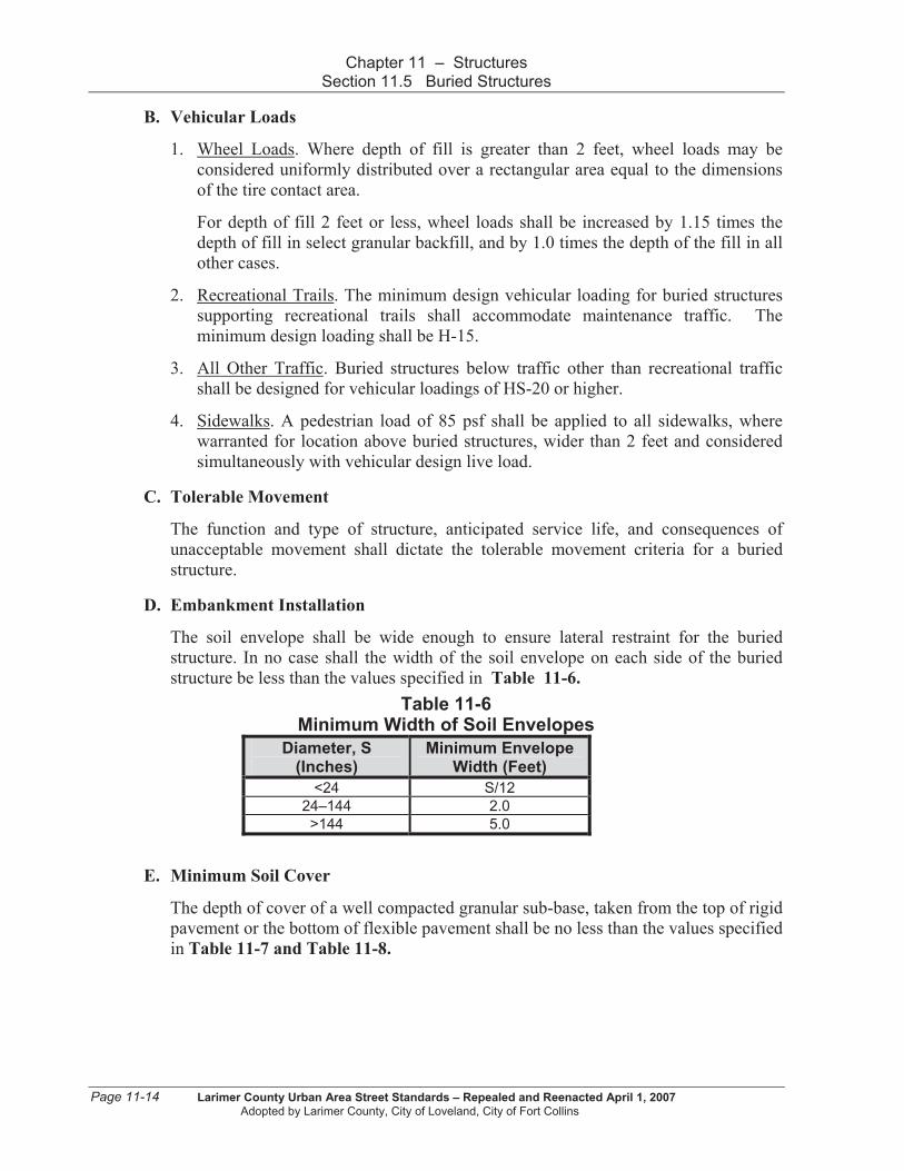
D. Embankment Installation
The soil envelope shall be wide enough to ensure lateral restraint for the buried
structure. In no case shall the width of the soil envelope on each side of the buried
structure be less than the values specified in Table 11-6.
Table 11-6 Minimum Width of Soil Envelopes
Diameter, S (Inches)
Minimum Envelope Width (Feet)
<24 S/12
24–144 2.0
>144 5.0
E. Minimum Soil Cover
The depth of cover of a well compacted granular sub-base, taken from the top of rigid
pavement or the bottom of flexible pavement shall be no less than the values specified
in Table 11-7 and Table 11-8.
Page 11-14 Larimer County Urban Area Street Standards – Repealed and Reenacted April 1, 2007
Adopted by Larimer County, City of Loveland, City of Fort Collins

Chapter 11 – Structures Section 11.5 Buried Structures
Table 11-7 Minimum Soil Cover for Buried Structures
Type Condition Minimum Cover
Structural Plate Pipe Structures
S/8>12.0 inches
Long Span Structural Plate Pipe Structures
Refer to Table 11-8
Structural Plate Box Structures
1.4 to 5.0 ft.
Unpaved areas and under flexible pavement
BBc/8 or B’c/8, (whichever is greater) 12.0 inches
Reinforced Concrete Pipe
Compacted granular fill under rigid pavement
9.0 inches
Thermoplastic Pipe ID/8 12.0 inches
Notes for Table 11-7:
S = diameter of pipe (inches) Bc = outside diameter or width of the structure (feet) B’c = out-to-out vertical rise to pipe (feet) ID = inside diameter (inches)
Table 11-8 Minimum Soil Cover for Buried Long Span Plate Pipe Structures
Minimum Cover, Feet
Top Radius, ft: 15.0 15 - 17 17 - 20 20 - 23 23 - 25
Steel Thickness Without Ribs, inches
.111 2.5 - - - -
.140 2.5 3.0 - - -
.170 2.5 3.0 3.0 - -
.188 2.5 3.0 3.0 - -
.218 2.0 2.5 2.5 3.0 -
.249 2.0 2.0 2.5 3.0 4.0
.280 2.0 2.0 2.5 3.0 4.0
F. Minimum Pipe Spacing
Multiple lines of pipe shall be spaced far enough apart to permit proper placement
and compaction of backfill below the haunch and between structures. Minimum
spacing shall not be less than that shown in Table 11-9. The utility companies may
have other spacing requirements that will use spacing greater than these requirements.
Larimer County Urban Area Street Standards – Repealed and Reenacted April 1, 2007 Page 11-15 Adopted by Larimer County, City of Loveland, City of Fort Collins

Chapter 11 – Structures Section 11.5 Buried Structures
Table 11-9 Minimum Pipe Spacing
Type of Structure Minimum Distance Between Pipes (Ft)
Round Pipes Diameter, D (ft)
2.0 1.0
2.0 – 6.0 D/2
6.0 3.0
Pipe Arches Span, S (ft)
3.0 1.0
3.0 – 9.0 S/3
9.0 – 16.0 3.0
Arches Span, S (ft)
All Spans 2.0
11.5.3 Structural Plate Box Structures
Structural plate box culverts are composite reinforced rib plate structures rectangular in
shape. These structures are relatively flat on top and require a large flexural capacity.
Structural plate box culverts are also called metal box culverts.
A. Design
The shallow covers and extreme shapes of box culverts require special design
procedures. Flexural requirements of metal box culverts govern the choice of section
in all cases.
B. Geometric Requirements
See Figure 11-6 and Table 11-10 for geometric requirements for structural plate box
structures.
Table 11-10 Geometric Requirements For Structural Plate Boxes
Parameter Required Range
Span, S 8’-9” to 25’-5”
Rise, R 2’-6” to 10’-6”
Radius of crown, rc < 24’-9 1/2”
Radius of haunch, rh > 2’-6”
Haunch radius included angle, 50 to 70 degrees
Length of leg, D (measured to the bottom of the plate)
4-3/4” to 71”
Minimum length of rib of leg, L
19"; D - 3"; or within 3" of top or footing(which ever is lowest)
C. Embankment Installation
The combined width of the soil envelope and embankment beyond shall be adequate
to support all the loads on the culvert.
Page 11-16 Larimer County Urban Area Street Standards – Repealed and Reenacted April 1, 2007
Adopted by Larimer County, City of Loveland, City of Fort Collins
Chapter 11 – Structures Section 11.5 Buried Structures
D. Live Loads
Live load distribution for culvert tops may be based on provisions for deck slabs
spanning parallel to traffic.
E. Maximum Soil Cover
Maximum soil cover for structural plate box structures shall be limited to a depth of
cover of 5 feet.
F. Concrete Relieving Slabs
Concrete relieving slabs may be used to reduce flexural moments in box culverts. The
length of the concrete relieving slab shall project at least 1 foot beyond the haunch on
each side of the culvert.
11.5.4 Reinforced Concrete Pipe
This section covers buried precast reinforced concrete pipes of circular, elliptical, and
arch shapes.
A. Design
Buried reinforced concrete pipes shall be designed to resist structural failure due to
flexure, thrust, shear, and radial tension. The dimensions of the pipe sections shall be
determined with either the direct or indirect design method as outlined in the
AASHTO standards referenced in Section 11.1.1 .
B. Trench and Embankment Installations
Both trench and embankment installations shall be designed for embankment
(positive projecting) loads and pressure distribution. The earth pressure distribution
shall be the Hedger pressure distribution as shown in Figure 11-7 and
Table 11-11.
Larimer County Urban Area Street Standards – Repealed and Reenacted April 1, 2007 Page 11-17 Adopted by Larimer County, City of Loveland, City of Fort Collins
Chapter 11 – Structures Section 11.5 Buried Structures
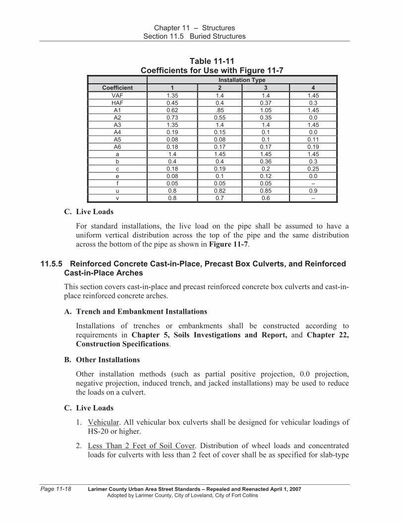
Table 11-11
Coefficients for Use with Figure 11-7 Installation Type
Coefficient 1 2 3 4
VAF 1.35 1.4 1.4 1.45
HAF 0.45 0.4 0.37 0.3
A1 0.62 .85 1.05 1.45
A2 0.73 0.55 0.35 0.0
A3 1.35 1.4 1.4 1.45
A4 0.19 0.15 0.1 0.0
A5 0.08 0.08 0.1 0.11
A6 0.18 0.17 0.17 0.19
a 1.4 1.45 1.45 1.45
b 0.4 0.4 0.36 0.3
c 0.18 0.19 0.2 0.25
e 0.08 0.1 0.12 0.0
f 0.05 0.05 0.05 –
u 0.8 0.82 0.85 0.9
v 0.8 0.7 0.6 –
C. Live Loads
For standard installations, the live load on the pipe shall be assumed to have a
uniform vertical distribution across the top of the pipe and the same distribution
across the bottom of the pipe as shown in Figure 11-7.
11.5.5 Reinforced Concrete Cast-in-Place, Precast Box Culverts, and Reinforced Cast-in-Place Arches
This section covers cast-in-place and precast reinforced concrete box culverts and cast-in-
place reinforced concrete arches.
A. Trench and Embankment Installations
Installations of trenches or embankments shall be constructed according to
requirements in Chapter 5, Soils Investigations and Report, and Chapter 22,
Construction Specifications.
B. Other Installations
Other installation methods (such as partial positive projection, 0.0 projection,
negative projection, induced trench, and jacked installations) may be used to reduce
the loads on a culvert.
C. Live Loads
1. Vehicular. All vehicular box culverts shall be designed for vehicular loadings of
HS-20 or higher.
2. Less Than 2 Feet of Soil Cover. Distribution of wheel loads and concentrated
loads for culverts with less than 2 feet of cover shall be as specified for slab-type
Page 11-18 Larimer County Urban Area Street Standards – Repealed and Reenacted April 1, 2007
Adopted by Larimer County, City of Loveland, City of Fort Collins

Chapter 11 – Structures Section 11.5 Buried Structures
superstructures. Minimum cover shall be as required in Chapter 12, Utility
Locations.
3. When Live Load Effects Can Be Ignored. For single-span culverts, the effects of
live load may be neglected where the depth of fill is more than 8 feet and exceeds
the span length. For multiple span culverts, the effects of live load may be
neglected when depth of fill exceeds the distance between faces of end walls.
4. No Soil Cover. If soil cover is not provided, the top of reinforced concrete box
structures shall be designed for direct application of vehicular and pedestrian
loads.
D. Crack Width Control
Steel reinforcement shall be well distributed over the zone of maximum concrete
tension to control flexural cracking.
11.5.6 Thermoplastic Pipe
This section covers buried thermoplastic pipe with solid, corrugated, or profile wall and
constructed of High Density Polyethylene (HDPE) or Polyvinyl Chloride (PVC).
A. Design
Buried thermoplastic pipes under roadways and driveways shall be designed to resist
structural failure due to thrust and buckling. Investigation of buckling shall be based
on the 100-year value for modulus of elasticity.
B. Localized Distortion
Maximum localized distortion of installed plastic pipe shall be based on the service
requirements outlined by AASHTO standards referenced in Section 11.1.1 and
overall stability of the installation.
C. Temporary Roadways
The design requirements for thermoplastic pipe may be relaxed for temporary
roadways or special conditions as approved by the Local Entity Engineer.
11.5.7 Precast Reinforced Concrete Three-sided Structures
This section covers three-sided precast reinforced concrete structures supported on a
concrete footing foundation.
A. Design
Design of three-sided structures shall be based on a pinned connection at the footing
and shall take into account anticipated footing movement. Each precast three-sided
structure shall be analyzed independently with no shear or stress transfer assumed
between sections.
Larimer County Urban Area Street Standards – Repealed and Reenacted April 1, 2007 Page 11-19 Adopted by Larimer County, City of Loveland, City of Fort Collins
Chapter 11 – Structures Section 11.5 Buried Structures
B. Geometric Requirements
The shape of precast three-sided structures, as specified by the manufacturer, may
vary in span, rise, wall thickness, haunch dimensions, and curvature. Wall thickness
shall be a minimum of 8.0 inches for spans under 24 feet and 10 inches for spans 24
feet and longer.
C. Shear Key
Flat top structures with shallow cover may experience differential deflection of
adjacent units; therefore, shear keys shall be provided in the top surface.
D. Minimum Reinforcement
The flexural reinforcement in the direction of span shall provide a ratio of
reinforcement/gross concrete area 0.002. This minimum reinforcement shall be
provided at all cross-sections subject to flexural tension, at the inside face of walls,
and in each direction at the top of slabs of three-sided sections with less than 2.0 feet
of fill.
E. Deflection Control
Deflection criteria shall be addressed in the design of all precast reinforced concrete
three-sided structures.
Page 11-20 Larimer County Urban Area Street Standards – Repealed and Reenacted April 1, 2007
Adopted by Larimer County, City of Loveland, City of Fort Collins