chapter 13a building an all-band hf receiver (part a) · chapter 13a building an all-band hf...
TRANSCRIPT

1. Chapter 13A, Harris
CRYSTAL SETS TO SIDEBAND © Frank W. Harris 2015, REV 13
Chapter 13A
BUILDING AN ALL-BAND HF RECEIVER (Part A) The Vanishing Art
The 1986 ARRL Amateur Radio Handbook reported that hardly anyone was building homebrew ham receivers. However, since I first wrote this chapter, articles about building small single-band receivers have become much more common in radio magazines. What remains rare are articles about building receivers that cover more than one band and cover the higher HF bands.
Out of hundreds of contacts, so far I’ve worked four guys, George, K7DU, Mike, NØMF, Biz, WDØHCO and Jack, W7QQQ who were using homebrew receivers for the QSO. Three of these receivers were made from vacuum tubes. George's receiver is a beautifully crafted instrument that looks like a commercial design from 50 years ago. All of these receivers had no trouble hearing me on 40 meter CW. I talked to one other fellow, Gil, N1FED who told me he had just finished a vacuum tube receiver. Unfortunately, it was performing so poorly he was still using his modern transceiver on the air. Gil told me he didn’t like transistors. I guess he found printed circuit boards and those pesky oscillations too much trouble.
In spite of this pessimism, you CAN build transistorized receivers that work reasonably well. I built mine because I was intrigued by mysterious circuits like “balanced mixers,” “product detectors,” “cascode amplifiers” and “crystal ladder filters.” Before this project, I could recite the purposes of these circuits, but I had no “feel” for how they worked and why receivers are designed the way they are. What better way to learn than to build one?

2. Chapter 13A, Harris
What’s a reasonable goal?
An “adequate performance” communications receiver
My receiver is based on the “High Performance Communications Receiver” designed by W7ZOI and K5IRK described in most of the annual ARRL Handbooks in the 1980s. In my opinion “High Performance” is optimistic, but certainly “adequate performance” is realistic. I define adequate sensitivity and noise figure to mean that I can hear the DX and QRPs that other stations are working. Before I built the receivers described here, I often had the impression I was hearing only the loudest signals. For me, adequate selectivity means that it's good enough for CW QSOs in the evening on 20 and 40 Meters. On these bands there are often dozens of narrow CW signals operating within a few hundred Hertz of each other. With a 10 KHz bandpass you may hear many stations simultaneously and not be able to copy any of them.
Adequate sensitivity will allow you to hear most QRP signals. I believe that 50 years ago hardly anyone had receivers that were adequate for QRP contacts. The modern band pass filters are a big part of this improvement. When I was a novice, my first transmitter was a 7-watt homebrew for 40 and 80 meters. It was a close copy of a design in the 1957 ARRL Handbook. I know it worked OK, because I talked to my novice buddies around town. Unfortunately I hardly worked anyone outside of town. It wasn’t until I bought a 50 watt commercial kit, just like all the other novices, that I was able to talk to the same stations my friends were working. I was still using the same dipole antenna, so I can only assume the improvement was the extra power.
The sensitivity of the receivers described in this chapter is well under 0.5 microvolt on 80 meters and the lower bands that have no RF preamplifiers. On the upper bands which have preamplifiers I could hear a calibrated signal source at 0.02 microvolts. Wow! No wonder I can hear those QRPs. In the old days sensitivity less than 1 microvolt was considered hot stuff.
Another issue is adequate stability. When your receiver is equipped with sharp crystal filters, it is vital that the VFO and crystal oscillators are stable enough that the signals you're listening to do not drift in and out of your passband. If you build a VFO like the ones described in chapter 10, drifting will not be a problem.
3. Chapter 13A, Harris
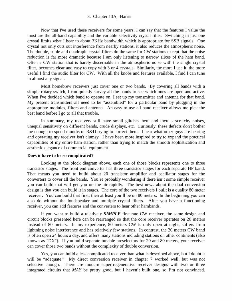
Now that I've used these receivers for some years, I can say that the features I value the most are the all-band capability and the variable selectivity crystal filter. Switching in just one crystal limits what I hear to about 3KHz bandwidth which is appropriate for SSB signals. One crystal not only cuts out interference from nearby stations, it also reduces the atmospheric noise. The double, triple and quadruple crystal filters do the same for CW stations except that the noise reduction is far more dramatic because I am only listening to narrow slices of the ham band. Often a CW station that is barely discernable in the atmospheric noise with the single crystal filter, becomes clear and easy to copy with 3 or 4 crystals. Similarly, the more I use it, the more useful I find the audio filter for CW. With all the knobs and features available, I find I can tune in almost any signal.
Most homebrew receivers just cover one or two bands. By covering all bands with a simple rotary switch, I can quickly survey all the bands to see which ones are open and active. When I've decided which band to operate on, I set up my transmitter and antenna for that band. My present transmitters all need to be "assembled" for a particular band by plugging in the appropriate modules, filters and antenna. An easy-to-use all-band receiver allows me pick the best band before I go to all that trouble.
In summary, my receivers still have small glitches here and there - scratchy noises, unequal sensitivity on different bands, crude displays, etc. Curiously, these defects don't bother me enough to spend months of R&D trying to correct them. I hear what other guys are hearing and operating my receiver isn't clumsy. I have been more inspired to try to expand the practical capabilities of my entire ham station, rather than trying to match the smooth sophistication and aesthetic elegance of commercial equipment.
Does it have to be so complicated?
Looking at the block diagram above, each one of those blocks represents one to three transistor stages. The front-end converter has three transistor stages for each separate HF band. That means you need to build about 20 transistor amplifier and oscillator stages for the converters to cover all the bands. You’re probably wondering if there isn’t some simple receiver you can build that will get you on the air rapidly. The best news about the dual conversion design is that you can build it in stages. The core of the two receivers I built is a quality 80 meter receiver. You can build that first, then at least you’ll be on 80 meters. In the beginning you can also do without the loudspeaker and multiple crystal filters. After you have a functioning receiver, you can add features and the converters to hear other hambands.
If you want to build a relatively SIMPLE first rate CW receiver, the same design and circuit blocks presented here can be rearranged so that the core receiver operates on 20 meters instead of 80 meters. In my experience, 80 meters CW is only open at night, suffers from lightning noise interference and has relatively few stations. In contrast, the 20 meters CW band is often open 24 hours a day, and offers many stations including stations on other continents (also known as "DX"). If you build separate tunable preselectors for 20 and 80 meters, your receiver can cover those two bands without the complexity of double conversion.
Yes, you can build a less complicated receiver than what is described above, but I doubt it will be “adequate.” My direct conversion receiver in chapter 7 worked well, but was not selective enough. There are modern super-regenerative receiver designs with two or three integrated circuits that MAY be pretty good, but I haven’t built one, so I’m not convinced.
4. Chapter 13A, Harris
Chapter 14 describes a vacuum tube regenerative receiver that was great fun to build and quite good for listening to foreign short wave broadcast stations. Unfortunately, it was NOT selective and stable enough for ham communications. In summary, YES, a versatile all-band ham receiver does have to be complicated.
Beginners' luck
I have built two of these all-band transistor receivers. I built the second one in hopes that I had conquered all the problems building the first one. The second receiver was supposed to have few imperfections. Wrong. When I built the first receiver, I was blessed with a great deal of beginners' luck. I thought I had learned the best mixer circuit, the best IF circuit and the best preselector. Not so. Also, when I built the first receiver, nearly all the band converter circuits worked immediately. In the second receiver only a few of them did. I wish you all a generous share of beginner's luck!
If you're not ready for such a long-term effort, I suggest starting with a single-band direct-coupled receiver like the one described in chapter 7. Alternatively a direct-coupled receiver that covers two bands would not be too difficult. Build two input preselectors and two VFOs with a multiple-contact rotary switch to jump from one band to the other. Unlike dual-conversion super-hetrodynes, DC receivers are remarkably easy to make work.
The good news about full function receivers is that the VFO problems and frequency converter issues are not nearly as severe as they are with transmitters. First, you can leave your VFO and crystal oscillators running while transmitting. This avoids the turn-on drift that usually occurs with ordinary oscillators. Also, the crystal oscillators don't need to run on precision-regulated 5 volts. On one of my bands I even used one of those awful digital crystal oscillator blocks but I wasn't bothered by drift. I'll bet it drifts like crazy for the first couple minutes when I turn it on, but apparently it soon settles down. I had forgotten I had used a oscillator block until I saw it in an old photo I had taken. In a transmitter you can't get away with those errors.
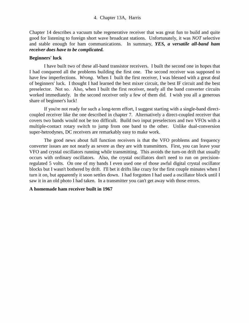
A homemade ham receiver built in 1967

5. Chapter 13A, Harris
A homebuilt ham receiver built in 1967 is shown above. It has 11 tubes, a simple crystal filter and covers 80 through 10 meters. It runs on either 12 volts DC using a germanium transistor charge pump. Or, it can use household power and run on 120 volts AC. It doesn’t cover the WARC bands. Yes, it works OK. But compared to the all-transistor receivers described in this chapter, it is insensitive, noisy and has poor selectivity.
Being realistic, any receiver you build is unlikely to match the performance of high-end commercial rigs. But every time your receiver brings in DX on a new band or whenever you conquer one of the dozens of glitches you will encounter, you’ll have a thrill and pride you’ll never get from a commercial rig. If you decide to build your own version of the W7ZOI / K5IRK receiver, I recommend you find a copy of an old ARRL Handbook from the 1980s and Xerox their original descriptions. You’ll find they built most circuit blocks differently than I did. Going back to the original description may give you some useful ideas. Perhaps their version will work out better for you. If you Google "W7ZOI / K5IRK," you'll find other examples of this classic receiver design.
PLANNING YOUR RECEIVER Superhetrodynes offer crystal filters for CW
A superhetrodyne uses a mixer to produce a constant intermediate radio frequency (IF). This intermediate frequency signal is always the same frequency so it can be filtered with fixed crystals or mechanical filters to establish bandpass widths for CW and upper and lower SSB. Before you commit to any design, make sure you can buy the critical parts you need, especially the crystal or mechanical filters for your IF. For example, many older receiver designs use a 455

6. Chapter 13A, Harris
KHz IF. Unfortunately, I have yet to find an easy source for 455 KHz crystals for building filters and BFOs. Consequently, I have avoided this frequency. Among homebuilt ham receivers the most common IF frequency seems to be 9 MHz.
Why not single conversion?
I had always wondered why homebuilt all-band HF receivers are almost always dual conversion. It turns out that the fundamental challenge of homebuilt receivers and transmitters is building a stable VFO. Yes, you can build a reasonably stable VFO, but homebrew VFOs usually don’t have much tuning range. 0.5 MHz is typical. And, in order to drift as few Hertz as possible, the VFO needs to be relatively low frequency. Homebrew VFOs are usually in the range of 2 to 7 MHz. The disadvantage of a low frequency VFO is that its harmonics will appear as a few loud whistles on some upper HF ham bands.
Compared to the practical VFO range of 2 to 7 MHz, the HF spectrum is huge, 1.8 to 30 MHz. Right away one can see that a homebrew direct conversion 10 meter receiver is difficult because it needs a stable VFO that will tune 28 to 29.7 MHz. This problem can be solved by “converting“ the VFO oscillator up to 28 MHz using a crystal controlled oscillator and a mixer plus all the 28 MHz filter/amplifiers. VFO converters are complex and moving the VFO for every band would require a complicated array of circuits which ruins the simplicity of direct conversion. If you have built a VFO converter for a transmitter on the upper ham bands, such as those discussed in chapter 11, then you understand the difficulty. A design like this is fine if you only want to tune a single high frequency band. But if you wish to tune all the bands, the receiver becomes a enormous stack of converters cobbled together with a complex band switch. If you’re going to operate above 40 meters, you may as well build dual conversion like the rest of us.
Birdies
A major disadvantage of this design is unavoidable "birdies." These are unwanted whistles that appear at fixed frequencies. The main cause is the 5 MHz VFO. A 5 MHz VFO has harmonics at roughly 10, 15, 20 and 25 MHz. The birdie at 21.3 MHz in the 15 meter band is particularly annoying. This is all a result of using a low frequency VFO in order to achieve frequency stability.
One of the loudest birdies is at 3.6 MHz. and occurs because of the "product detector" circuit. The product detector is by far the most useful detection method. The product detector uses a 9 MHz crystal oscillator BFO signal in order to extract the modulation. Product detectors are much more sensitive than the AM and FM detectors I have built and allow me to listen to CW and SSB signals. The bad news is that the BFO is a major contributor to birdies. The product detector needs the 9.000,000 MHz BFO sinewave to serve as a replacement for a carrier signal. When a CW Morse code signal is offset from the tuned frequency by 700 Hz, This makes the CW intelligible as if it were an AM modulated 700 Hz audio tone. For SSB the BFO is tuned to 9.000,000, which is where the original AM voice carrier would have been located.
As I should have expected, when listening to exactly 3.6 MHz, the 5 MHz VFO is tuned to 5.4 MHz. Therefore two oscillators in the receiver are operating simultaneously at 9 MHz and 5.4 MHz. Whenever two oscillators generate signals at once, difference and sum frequencies are inevitable. These are 9.00 - 5.4 = 3.6 MHz and 9.00 + 5.4 = 14.4 MHz. When I switch to the

7. Chapter 13A, Harris
AM or FM detectors, the 9 MHz BFO is turned off and the birdies vanish. Fortunately, 14.4 MHz is outside the 20 meter ham band. There are more birdies that appear on the upper bands.
How do modern receivers do it?
Modern receivers use integrated circuit frequency synthesizers to generate stable VFO signals anywhere they like. Sometimes modern HF receivers escape from artifact images and harmonics by using an IF frequency way up in the VHF range. In addition, after the initial mixer stage, some commercial receivers use multiple conversions to get the signal back down to an audio output. At each conversion stage, different kinds of filtering are applied. For example, the Yaesu FT1000MP has four down-conversions from an 89 MHz IF! These include the digital signal processor with its 32 KHz input.
In a superhetrodyne the VFO interacts with the incoming RF signals to produce an intermediate (IF) frequency. A 5 MHz VFO implies that the IF is going to be within 5 MHz of the band or bands it covers. Such a receiver might cover 28 MHz, but that would imply an IF of 23 MHz or possibly 33 MHz. The lower bands would be out of range unless the VFO could be tuned over many MHz. Consequently, a single conversion homebrew superhetrodyne can only cover one band well. It can’t cover the whole spectrum without moving the VFO frequency for each band.
In some old ham designs the VFO tuned 5.2 to 5.7 MHz. They used a 1.7 MHz IF and either subtracted or added the IF to the VFO frequency to cover either 80 or 40 Meters. Specifically, 5.7 MHz minus 1.7 MHz = 4.0 MHz or 5.3 MHz plus 1.7 MHz = 7.00 MHz.)
Homebuilt, all-band, transistorized, dual conversion, HF ham receivers.
Start with a single band, single conversion superhetrodyne
My two "adequate receivers" are shown above. The one on the right was my first. The panel measures 7 by 7 inches and the chassis is 11 inches deep. The receiver on the left is the new and improved model. The panel measures 8 by 10 inches and the chassis is 14 inches deep. Referring to the receiver on the right, above the frequency dial there is a bargraph S-meter. The S (Strength) meter is useful for zeroing in my transmitter VFO onto a station I wish to call. Unfortunately, the bargraph produces digital switching noises that often interfere with weak signals. When I substitute the analog meter on the left, the noise vanishes. You'll notice that I planned for an analog meter on the second receiver. If you have loads of time, you can make

8. Chapter 13A, Harris
your receiver beautiful with transfer labels, paint and extra craftsmanship. As you can see, beauty has not been a high priority for me.
My 80 meter receivers have a 9 MHz IF. 9.00 MHz crystals are available for about $0.60 from Digi-Key and Mouser. I just saw 9 MHz crystals at Jameco for $0.22! In the bad old days, crystals were $20 each and dollars were bigger back then. The low price is important because, depending on your filter plans, you may need as many as 15 or more 9 MHz crystals. When making filters you must select matched frequency individual crystals from your collection.
It may occur to you to design the receiver to work directly on 20 meters, that is, 14 MHz. Notice that 5.0 MHz VFO + 9 MHz IF = 14 MHz. This will work well, except that 20 meters needs an additional tuned RF pre-amplifier to give you adequate sensitivity.
An 8 MHz IF wasn’t a good idea
At first I used the more common 8.0 MHz standard microprocessor crystals. Unfortunately, to receive 4.0 MHz, the VFO had to tune 4.0 MHz. I expected the 4.0 MHz VFO signal would be “a little birdie” that would mark the high end of the 75/80 meter band. I thought this “edge-of-band marker” would be rather convenient. Instead, the “birdie” was more like a screaming siren that overwhelmed the IF and made the upper end of the ham band unusable. So when my 9.0 MHz crystals arrived, I rebuilt everything for 9 MHz. Now the VFO (the big tuning knob on the receivers) tunes 5.0 to 5.5 MHz to cover 4.0 to 3.5 MHz. That is, 5.0 MHz + 4.0 MHz = 9.0 MHz. Of course the Beat Frequency Oscillator (BFO) frequency also had to change from 8 MHz to 9 MHz.
An unusual adventure
Once your receiver begins to work, you’ll have interesting glitches. Until I got my 80- meter preselector filter working, I usually heard rap music from my local 1190 KHz AM radio. Also, the 31 meter shortwave band is just above the 9 MHz IF. Before it was aligned, I was hearing sermons from HCJB in Quito, Ecuador. Later, my 20 meter converter was overwhelmed by Dr. Scott, a Los Angeles evangelical minister, who preaches on 13.85 MHz. Once I had my modules tuned and sealed, Dr. Scott and his friends were silenced. Actually, I got a kick out of these problems.
Building a receiver revived my interest in shortwave listening. I’ve had shortwave radios since I was a kid. Some of them, like my Army surplus Collins R-388/URR, were excellent. In spite of this, I rarely listened when I wasn’t actively hamming. But once my homebrew receiver(s) began to work, I found myself exploring the bands as never before. For instance, on 80 meters I was amazed to hear hams from all over the continent. I had heard about guys who work DX and earn WAS certificates (Worked All States) on 80 meters, but I never really believed it. I have even worked QRP stations on 80 meters. 80 meters is usually so noisy, I didn’t know that was possible. Until I built this receiver, I had never heard “spy code stations” before. Most of these mysterious stations are CW “spy stations” sending Morse code 5 letter groups, just like the WWII Enigma signals. Occasionally some of them have an announcer reading what sound like random letter groups. I often hear them on 10 and 30 meters. Transmitting without identifying yourself and using secret codes is illegal, so I assume they really are spies. As I built converters for each of the HF bands, it was like hearing those bands for the first time. 40, 30, 20 and 17 meters are interesting because they are near to shortwave broadcast
9. Chapter 13A, Harris
bands which I hadn’t listened to in years.
Building with modules
Aside from the need to shield circuit blocks from one another, a homebrew receiver with a single big board full of discrete components has another problem. If you build the whole thing at once without buying a kit and pre-cut board, I guarantee it won’t work. To make homebrew stuff that works, you have to develop your own technology based on parts you can get and circuits you understand. Learning to think this way was difficult for me. Rather than “building a receiver,” I had to lower my sights and build one circuit at a time, e.g., “an oscillator,” “a mixer,” “an audio amplifier,” etc. Then I put the blocks together to complete my project. Some of these circuit blocks didn’t work the first time so I had to build a new block. There were various reasons the modules didn’t work. Usually, I wasn’t able to buy the exact parts used in the circuits I was copying. Or my craftsmanship or shielding wasn’t adequate. Sometimes I never did learn why one version of a circuit block was superior to another. By building my receiver using separate little shielded modules for each circuit block, I could replace a circuit block whenever I managed to build an improved version. Otherwise, I would have ruined the entire big board.
On rare occasions my circuits didn’t work because there were errors in circuit diagrams in QST magazine or in the handbooks. I found some serious errors in my 1979 ARRL Handbook and a minor one in my 1998 edition. Perfect editing is not possible, so we shouldn’t expect it. I apologize, but this book also has errors. When building my second receiver, I discovered that I had listed an incorrect crystal frequency for the 12 meter converter in Revision 12 of this book. If painstaking R & D is new for you, prepare for a long battle. On the other hand, you’ll learn a lot and victory will be especially sweet.
Don't scrap a homebrew receiver until you have a replacement! If you already have a working homebrew gizmo, don't scrap it for parts until your new device is working better.
10. Chapter 13A, Harris
MECHANICAL CONSTRUCTION
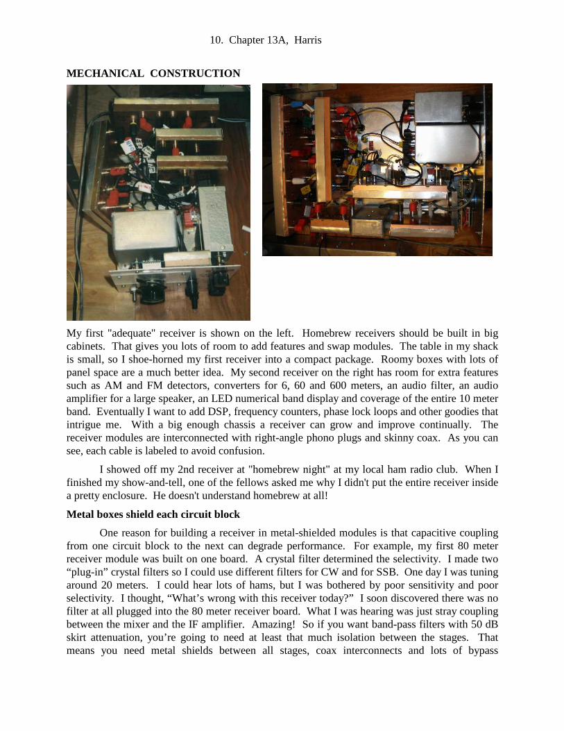
My first "adequate" receiver is shown on the left. Homebrew receivers should be built in big cabinets. That gives you lots of room to add features and swap modules. The table in my shack is small, so I shoe-horned my first receiver into a compact package. Roomy boxes with lots of panel space are a much better idea. My second receiver on the right has room for extra features such as AM and FM detectors, converters for 6, 60 and 600 meters, an audio filter, an audio amplifier for a large speaker, an LED numerical band display and coverage of the entire 10 meter band. Eventually I want to add DSP, frequency counters, phase lock loops and other goodies that intrigue me. With a big enough chassis a receiver can grow and improve continually. The receiver modules are interconnected with right-angle phono plugs and skinny coax. As you can see, each cable is labeled to avoid confusion.
I showed off my 2nd receiver at "homebrew night" at my local ham radio club. When I finished my show-and-tell, one of the fellows asked me why I didn't put the entire receiver inside a pretty enclosure. He doesn't understand homebrew at all!
Metal boxes shield each circuit block
One reason for building a receiver in metal-shielded modules is that capacitive coupling from one circuit block to the next can degrade performance. For example, my first 80 meter receiver module was built on one board. A crystal filter determined the selectivity. I made two “plug-in” crystal filters so I could use different filters for CW and for SSB. One day I was tuning around 20 meters. I could hear lots of hams, but I was bothered by poor sensitivity and poor selectivity. I thought, “What’s wrong with this receiver today?” I soon discovered there was no filter at all plugged into the 80 meter receiver board. What I was hearing was just stray coupling between the mixer and the IF amplifier. Amazing! So if you want band-pass filters with 50 dB skirt attenuation, you’re going to need at least that much isolation between the stages. That means you need metal shields between all stages, coax interconnects and lots of bypass
11. Chapter 13A, Harris
capacitors for the power supply wires.
The metal-shielded modules can be small circuit boards mounted in commercial boxes. What I usually do is make shallow rectangular boxes out of two-sided circuit board material soldered together. The circuit is then carved into the floor of the box, one circuit at a time, using small wood-carving chisels. The press-fit lid of the box is made from thin, sheet aluminum folded over the corners of the PC board box.
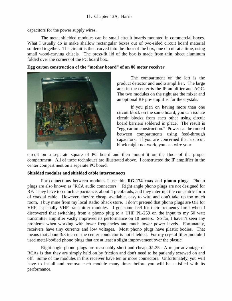
Egg carton construction of the “mother board” of an 80 meter receiver
circuit on a separate square of PC board and then mount it on the floor of the proper compartment. All of these techniques are illustrated above. I constructed the IF amplifier in the center compartment on a separate PC board.
Shielded modules and shielded cable interconnects
For connections between modules I use thin RG-174 coax and phono plugs. Phono plugs are also known as "RCA audio connectors." Right angle phono plugs are not designed for RF. They have too much capacitance, about 4 picofarads, and they interrupt the concentric form of coaxial cable. However, they’re cheap, available, easy to wire and don't take up too much room. I buy mine from my local Radio Shack store. I don’t pretend that phono plugs are OK for VHF, especially VHF transmitter modules. I got some feel for their frequency limit when I discovered that switching from a phono plug to a UHF PL-259 on the input to my 50 watt transmitter amplifier vastly improved its performance on 10 meters. So far, I haven’t seen any problems when working with lower frequencies and much lower power levels. Fortunately, receivers have tiny currents and low voltages. Most phono plugs have plastic bodies. That means that about 3/8 inch of the center conductor is not shielded. For my crystal filter module I used metal-bodied phono plugs that are at least a slight improvement over the plastic.
Right-angle phono plugs are reasonably short and cheap, $1.25. A major advantage of RCAs is that they are simply held on by friction and don't need to be patiently screwed on and off. Some of the modules in this receiver have ten or more connectors. Unfortunately, you will have to install and remove each module many times before you will be satisfied with its performance.
The compartment on the left is the product detector and audio amplifier. The large area in the center is the IF amplifier and AGC. The two modules on the right are the mixer and an optional RF pre-amplifier for the crystals.
If you plan on having more than one circuit block on the same board, you can isolate circuit blocks from each other using circuit board barriers soldered in place. The result is “egg-carton construction.” Power can be routed between compartments using feed-through capacitors. If you are concerned that a circuit block might not work, you can wire your
12. Chapter 13A, Harris
TV cable connectors, the ones that use the coax inner wire as a male connector pin, are superior to phono plugs for RF, but they are dreadfully intermittent. Personally, I’ve found them almost unusable and after many years the TV industry finally seems to have stopped using them. There is a TV-compatible “F” type luxury connector that is excellent, but is much too large and expensive, $22 each. In general, first rate RF connectors like BNC, SMA or TMA cost $2 - $6 each, often $12 for a mated pair. Tiny SMA connectors come in many shapes and styles including right angle and they look ideal. Some connectors are hard to assemble and your receiver could easily contain $500 worth of “proper” connectors. Also, most of these connectors are too long to fit gracefully in a small receiver. Finally, these quality connectors screw on an off, which is rugged and reliable. Unfortunately, screw-on outer shields are a royal pain when you need to remove your IF amplifier or other large module for adjustment or modification.
Use plastic knobs and screw the modules down securely
One strange problem I encountered with the first receiver was that touching the metal control knobs or the front panel sometimes caused scratchy noises in the headphones when I listened on the higher bands. Yes, the metal panel was grounded and the chassis was wired to the station ground. The station ground is a heavy 12-gauge wire that grounds all the various metal boxes to a copper water pipe next to the station. I don’t have an explanation for the noises, but I switched from metal to plastic knobs and the annoying scratchy noises greatly improved. What really puzzles me is that, when I built the 2nd receiver, there are no scratchy noises and metal knobs work just fine.
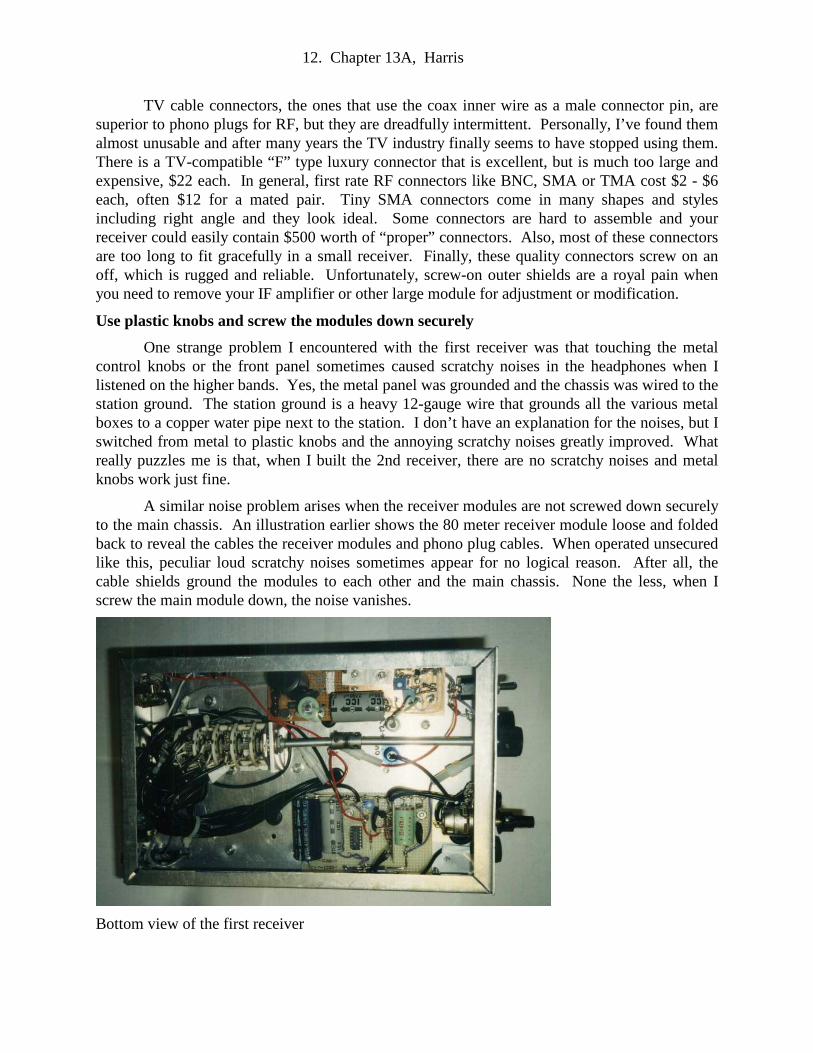
A similar noise problem arises when the receiver modules are not screwed down securely to the main chassis. An illustration earlier shows the 80 meter receiver module loose and folded back to reveal the cables the receiver modules and phono plug cables. When operated unsecured like this, peculiar loud scratchy noises sometimes appear for no logical reason. After all, the cable shields ground the modules to each other and the main chassis. None the less, when I screw the main module down, the noise vanishes.
Bottom view of the first receiver
13. Chapter 13A, Harris
Band switching and power supplies
The precision power supply for the VFO is at the top right. To help keep the VFO stable, the VFO is left running while transmitting. The low drop-out regulated supply for the rest of the receiver is at the bottom right. This power supply is shut off whenever the transmitter is activated. These are the same circuits used earlier with the transmitter VFO and QRP transmitter modules. The band-switch is the multi-wafer ceramic switch on the left. The black wires on the left are skinny RG-174 coax that interconnect the inputs and outputs of the converters for every ham band except 80 meters. It is desirable to cover the bottom with a metal plate to help keep stray signals out of the power leads.
Mechanical shaft extenders
In the photo above the band switch is connected to the front panel with a long, 1/4 inch diameter shaft extender. Since the 9 band converters were located at the back of the chassis, it was convenient to have the multi-gang switch at the rear of the cabinet. Also, shaft extenders decrease the traffic jam behind a small front panel. Many receiver modules, such as the preselector and the BFO, have considerable bulk adjacent to the control shafts and prevent mounting other controls nearby.
Unfortunately, shaft extenders are hard to find in the modern world. On my new receiver I made them from 1/4 inch diameter brass shafts. Metal tubing or even extra-long threaded 1/4" bolt shafts could be used. They can be coupled to the distant capacitor, pot or rotary switch using a short piece of rubber automotive fuel line which has a 1/4" internal diameter. Small fuel line clamps hold the rubber in place. The rubber coupling can flex so that perfect alignment isn't necessary. I disassembled old potentiometers and used their 1/4 inch shaft bushings to make low friction, low vibration bearings through the front panel.
THE ELECTRONIC MODULES
80 Meter input preselector
The “front end” of the 80 meter receiver is a mixer. No RF pre-amplifier is needed on 80 meters because, if the receiver works well, then the atmospheric noise coming in from the antenna will be louder than the receiver internal noise. In this situation an RF amplifier won’t help. However, the mixer does need a sharply tuning bandpass “preselector” filter to keep out the low frequency AM radio and limit the input signals to 3.5 to 4.0 MHz. The mixer subtracts the VFO frequency, (5.0 to 5.5 MHz) from the IF frequency, (9 MHz), to tune 80 meters, (3.5 to 4.0 MHz). The two inputs to the mixer are the VFO signal and the antenna signal from the 80 meter band.
Guess what happens when you leave out the preselector? Since the IF works at 9 MHz, you will hear the 9 MHz (31 meter) shortwave broadcast band. If you don't have a crystal filter in your IF and an antenna tuner on the antenna, it will tune poorly and you'll hear all of the powerful 9 MHz shortwave stations at once. You will probably also hear some 80 meter stations, some 20 meter stations and some AM broadcast stations as well. I discovered by accident that, when I was listening through an antenna tuner described in chapter 9, I could use it to tune in the loudest 9 MHz broadcast station interference-free. Switching in just one 9 MHz crystal in front of the IF amplifiers removes most of the 9 MHz broadcast stations, even with no metal shield over the IF strip.

14. Chapter 13A, Harris
Preselector designs
When I first examined the 1986 ARRL design, I was disappointed to see that the pre-selector had a primitive-looking variable capacitor that the operator was supposed to tune for maximum gain for a particular part of the band. After all, the bandpass filters for the other HF bands were fixed and not accessible from the front panel. I attempted to build my own fixed bandpass filter, but my filters had too much attenuation (poor sensitivity) and sometimes let in AM broadcast stations. That is, it was like listening to a crystal set.
The recommended 80 Meter preselector filter for the core receiver mixer input.
So I returned to the W7ZOI/K5IRK design with the 365 pF variable capacitor. It had so much attenuation on 80 meters, I couldn’t hear a thing. I ran this circuit on a Spice circuit simulation program and, according to Spice, it should have worked, but mine didn’t. Using trial and error, I removed some parts and ended up with the circuit shown below.
My first adequate version of the 80 Meter preselector filter for the mixer input
This filter works pretty well, but it's vulnerable to AM broadcast signals. When I ran it on a Spice circuit simulator program, Spice confirmed that it is indeed sensitive to AM signals. The little broadcast filter from Chapter 7 solved my interference problem. Because I had built it in a little box with phono plug connectors, I simply plugged it in without building anything new and without altering the rest of the receiver. It worked best connected in between the 80 meter preselector module and the 80 meter mixer/IF module.
The 365 pF variable capacitor acts like an attenuator
An advantage of the variable peaking capacitor is that it's quite useful as an attenuator for receiving strong single sideband signals. In other words, strong SSB phone signals are usually much more intelligible when the preselector is mistuned and signal strength is decreased. If I didn't have this capacitor as a variable sensitivity control, I would have to build an attenuator. The IF gain control doesn't work for this purpose because it is the mixer stage that is sensitive to overload and the IF gain is located after the mixer, not in front of it.

15. Chapter 13A, Harris
The preselector is built in a little box up front behind the front panel. This is the preselector I used in my first receiver. Notice the long white wire connecting the variable capacitor - that's bad practice. Don't do that!
The search for a quality preselector
When I built my second receiver I tried again to build a first rate preselector. I reworked the original W7ZOI/K5IRK version on both Spice simulation and a real prototype. Unfortunately, no matter what I did, the real circuit attenuated the desired signals about 20 dB (90% voltage loss) which was impractical. The converters for the other ham bands described later in the next chapter need similar preselectors and (amazingly) they usually work well. Accordingly I scaled up those values to work on 80 meters. Using Spice and trial and error, I developed the design below. (Don't start soldering, it still wasn't working in the real world.)
By the way, you may be wondering where I find all the oddball picofarad capacitor values used in my receiver and sideband transmitter. They are parallel combinations of two or even three capacitor values that I happened to have in my parts collection. For example, the 1720 pF capacitor shown above was a 1500 pF ceramic capacitor in parallel with a 220 pF capacitor. A tiny capacitor, such as C7 above, often needs a variable capacitor to be optimum.

16. Chapter 13A, Harris
The preselector (upper) and BFO module (lower) in the second receiver chassis. They look nice, don't they? Too bad the preselector worked so poorly.
Spice simulations and reality are different
Unfortunately designing and building the filter and making it work are three different challenges. According to the computer simulation, the preselector shown above is marvelous and produces bigger voltages in the 80 meter band than were coming in from the antenna! Unfortunately, in the real world the circuit produced the usual huge attenuation and didn't peak in the 80 meter band. Oops. This discrepancy is due to the complexity of the design. In the real world every component lead is a tiny inductor. Every trace on the PC board is a capacitance to ground and every component near another component is a unwanted capacitor. Skinny wires have more inductance than fat wires. By the time you build it, your prototype and the pure circuit are quite different. In short, I can't recommend building this.
After several failed attempts to build a complex preselector, I returned to a simple circuit, much like the one used as the preselector in the Chapter 7 direct coupled receiver. Being cautious, I breadboarded it by soldering parts onto an old, used PC board using long component leads. Although the circuit was correct, the attenuation and inability to tune were amazingly bad. It finally hit me: Not only does the circuit have to be simple, the leads on the components must be really, really short, even at 3.5 MHz. I had naively thought that, compared to 80 meters (wavelength 3,144 inches), a few inches of extra wire would be insignificant. Wrong. The following circuit was developed on the "5Spice" program:

17. Chapter 13A, Harris
And below is the circuit performance simulated on the computer. Notice how the attenuation is extreme everywhere but inside the 80 meter band where it tunes sharply. The multiple traces are various settings of the 440 pF variable capacitor. Nice, huh?
So, I built it and, of course, it didn't work. However, using a signal generator and an oscilloscope, I tweaked the components until it tuned just like the computer simulation. First, I connected a 1000 ohm load to the oscilloscope probe and swept the frequency spectrum to be
18. Chapter 13A, Harris
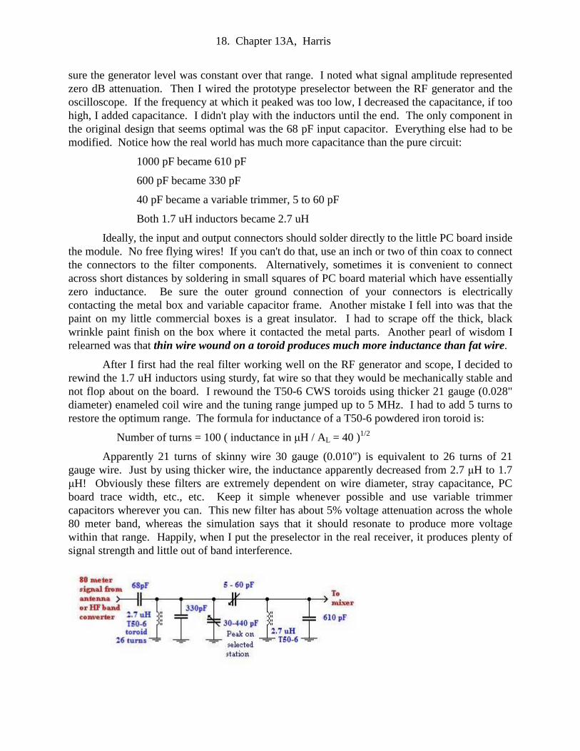
sure the generator level was constant over that range. I noted what signal amplitude represented zero dB attenuation. Then I wired the prototype preselector between the RF generator and the oscilloscope. If the frequency at which it peaked was too low, I decreased the capacitance, if too high, I added capacitance. I didn't play with the inductors until the end. The only component in the original design that seems optimal was the 68 pF input capacitor. Everything else had to be modified. Notice how the real world has much more capacitance than the pure circuit:
1000 pF became 610 pF
600 pF became 330 pF
40 pF became a variable trimmer, 5 to 60 pF
Both 1.7 uH inductors became 2.7 uH
Ideally, the input and output connectors should solder directly to the little PC board inside the module. No free flying wires! If you can't do that, use an inch or two of thin coax to connect the connectors to the filter components. Alternatively, sometimes it is convenient to connect across short distances by soldering in small squares of PC board material which have essentially zero inductance. Be sure the outer ground connection of your connectors is electrically contacting the metal box and variable capacitor frame. Another mistake I fell into was that the paint on my little commercial boxes is a great insulator. I had to scrape off the thick, black wrinkle paint finish on the box where it contacted the metal parts. Another pearl of wisdom I relearned was that thin wire wound on a toroid produces much more inductance than fat wire.
After I first had the real filter working well on the RF generator and scope, I decided to rewind the 1.7 uH inductors using sturdy, fat wire so that they would be mechanically stable and not flop about on the board. I rewound the T50-6 CWS toroids using thicker 21 gauge (0.028" diameter) enameled coil wire and the tuning range jumped up to 5 MHz. I had to add 5 turns to restore the optimum range. The formula for inductance of a T50-6 powdered iron toroid is:
Number of turns = 100 ( inductance in µH / AL = 40 )1/2
Apparently 21 turns of skinny wire 30 gauge (0.010") is equivalent to 26 turns of 21 gauge wire. Just by using thicker wire, the inductance apparently decreased from 2.7 µH to 1.7 µH! Obviously these filters are extremely dependent on wire diameter, stray capacitance, PC board trace width, etc., etc. Keep it simple whenever possible and use variable trimmer capacitors wherever you can. This new filter has about 5% voltage attenuation across the whole 80 meter band, whereas the simulation says that it should resonate to produce more voltage within that range. Happily, when I put the preselector in the real receiver, it produces plenty of signal strength and little out of band interference.

19. Chapter 13A, Harris
Here is the final working preselector. Building modules that actually work makes it likely that they will be solder-spattered and ugly by the time you succeed. You are not Icom or Yeasu, so don't let imperfection bother you!
At this point I had a functional 80 meter preselector that peaked well anywhere in the band, just like the computer simulation. However, I was still annoyed by random stray birdies. They aren't severe and I can live with them. What I really needed was a band pass filter that would filter out every signal below 3.5 MHz and every signal above 4.0 MHz. With my first receiver I rescued the performance by placing an AM broadcast elimination filter between the pre-selector and the mixer (as in Chapter 7). I plugged the same old filter into the new receiver. It helped noticeably, but I lost some gain and still had a few stray whistles. RF filtering the +12 volt DC entering the receiver eliminated a few more. Apparently compromise is necessary between images, birdies and receiver sensitivity. I am told that, if you read the fine print in the manuals of top-of-the-line modern transceivers, even the best manufacturers admit to having a few minor birdies and images. We all must decide on what trade-offs we can live with.
I eventually built an additional filter module that contains the broadcast rejection filter from chapter 7 and an 80 meter low pass filter resulting in a "notch filter." It hopefully rejects any signal that is not in the 80 meter band. I can plug it in and out at will and, once I had the rest of the receiver working properly, there did not seem to be an advantage to using this extra filtering.
The variable frequency oscillator (VFO)
The receiver VFO can be any of the designs for 5 MHz VFOs which were described in chapter 10. The big tuning knob controls the VFO. Actually, in superhetrodynes the VFO is usually called a local oscillator or LO. The range and stability of the VFO determine what VFO and IF frequencies are practical. Like a transmitter VFO, a receiver VFO ideally should be stable to less than 20 Hz. Receiver VFOs are less critical because you may leave the VFO on full time so it has time to stabilize.

20. Chapter 13A, Harris
A varactor tuned 5 MHz VFO. Tuning is done with the pot with the black knob. The blue pot is the bandspread. I find the bandspread extremely useful for tuning in single sideband stations.
Unfortunately, if the VFO frequency is too low, it probably won’t span enough Hz to cover the bands you’re interested in. Notice that 10 meters is so huge, 1.7 MHz wide, that you will have to cover it with multiple converters. My first receiver just tuned the first 500 KHz of 10 meters, which includes all the CW activity. It also usually covers the majority of the SSB signals. We haven't had good sunspot propagation on 10 meters in so many years, that I really don't know much about the band. However, my friends tell me that coverage above 28.5 MHz is only useful when the band becomes active and crowded. The upper 100 KHz is reserved for ham FM signals which are rarely heard. FM requires an FM detector rather than a product detector. My second receiver has a 4 band converter that covers 28.0 to 29.7 MHz, but I have yet to hear an amateur signal above 28.5 MHz.
Using one VFO for both the receiver and a remote transmitter?
In theory, a common VFO for receiver and transmitter would be a great help on the air. I attempted to do that, but immediately ran into serious difficulties. If you use a common VFO on CW, you will have to master the 500 to 800 Hz send/ receive frequency-offset problem. Also, an isolation system is needed to keep the cable connecting one unit to the other from loading down the master VFO. And finally, although the main VFO frequency may be the same, the receiver converter crystal oscillator and each crystal oscillator in the transmitter PMOs must be the same so that the receiver will listen to exactly the same frequency used by the transmitter, offset by +/-500 to 700 Hz, of course. In other words all the converter oscillators need to be shared too. It makes the most sense to build a transceiver from the beginning, starting with an enormous mainframe cabinet.
How much VFO signal voltage do you need?
As explained in chapter 10, the stability of a VFO is partly dependent on generating the minimum heat possible inside the VFO box. Therefore, you should decide out how much VFO signal voltage you will need before you build the VFO. The required VFO voltage is the level needed to drive your mixer. MOSFET and JFET mixers only need 1 or 2 volts peak, so if you're
21. Chapter 13A, Harris
going to use one of these, there is no reason to generate 5 volts, then throw away most of it in a potentiometer at the input to the 80 meter mixer. Instead of running the VFO on 12 volts or 5 volts, you can reduce the supply voltage externally to 2.5 volts or whatever minimum voltage you actually need. Remember that low voltage produces less heat which means less frequency drift.
Mixer magic The purpose of a mixer is to translate the frequency of an incoming radio signal to a constant intermediate frequency (IF) that can be amplified and filtered more easily. Mixers combine a local oscillator sinewave with the incoming radio signal to make a composite signal. The new signal contains the original frequencies, plus the new sum and difference frequencies. Mixers intended for moving a VFO up to a high band were described in chapter 11. Mixers for that purpose can be quite crude and still work well. Unfortunately, receiver mixers are much more difficult because the incoming signal is usually tiny.
One way to look at mixers is that a big local oscillator sinewave keys the incoming RF signal totally on and off, much like a sequence of really fast Morse code dots. The lesson is that the local oscillator (the VFO tuning knob) must be a big signal while the RF input signals may be arbitrarily small.
The ARRL Handbooks present several different mixer designs made with discrete diodes, inductors and transistors. However, in most ARRL receiver designs since the 1980s, including the W7ZOI - K5IRK receiver, the mixer is an integrated circuit or a little canned assembly labeled “mixer.” I guess everyone else was having mixer trouble too so they resorted to integrated circuits. Recent receiver projects in QST use ICs that contains both the mixer and the VFO. Most modern projects are using little digital modules that even read out the frequency. I’ll bet these marvels work well, but the contents are a mystery. Use one if you want.
Mixers will give you lots of static... and squeals, howls and squawks
So far I’ve built seven different mixer designs from discrete parts. First I built a classic balanced mixer with ferrite cores and a "hot carrier" diode ring. When I turned it on, I heard loud roaring static in the headphones. “Oh goodie!” I thought, “Listen to all that atmospheric static! It must be working!” I soon figured out that the static was coming from the mixer and the IF amplifiers and had nothing to do with the outside world. I had just learned a basic truth about mixers: Mixers aren’t just prone to generate “a little background noise.” They often produce gigantic Niagara Falls noise that obscures everything coming in the antenna. However, once I had proper mixer input levels and resonant circuits tuned up as best I could, the noise disappeared and I began to hear stations. Unfortunately, as I tuned across the band, there were loud whistles like marker beacons every few KHz. In between the whistles, I could sometimes barely hear strong stations.

22. Chapter 13A, Harris
A practical mixer
My favorite mixer is shown above. Most of the others suffered from noise and “birdies” and had poor sensitivity as well. Unlike diode mixers, the operation of the MOSFET mixer is obvious. It is essentially an ordinary transistor RF amplifier. The radio signals come in on one control gate. This modulates the large current passing from drain to source of the transistor. The small voltage on the control gate controls the large drain current thereby amplifying the original signal. A second input gate amplifies the local oscillator signal. This means that 2 volts peak-to-peak of VFO signal is plenty. The local oscillator signal is so strong it turns the drain to source current totally on and off, “chopping” the input RF signal into tiny segments. The big output current from the transistor becomes an amplified “mixture” of the two input signals.
You could also build the mixer as a broadband untuned dual input amplifier. Replace the transformer with an FT50-61 ferrite core with 20 turns primary and 4 turns secondary. The broadband version has slightly less gain but it doesn't have its peak sensitivity in one part of the band. To my surprise the untuned version tends to produce more "birdies" and whistles across the band. When I changed it back to the tuned version, the new birdies disappeared. If birdies aren't a problem for you, the untuned version is better because its response is equally sensitive across the band.
As explained above, the VFO sinewave signal can be low amplitude, typically 2 volts peak to peak. In contrast, a diode ring mixer needs a big local oscillator signal to chop the signal, 12 or more volts peak. Other transistor mixer designs use junction FETs. These designs use the emitter resistor as the VFO input port. In other words, the VFO signal is applied across the resistor, so in theory, they need more VFO signal. Though in practice, not as much as I expected. In any case, you can adjust the input with the 500 ohm trimmer pot.
I experimented briefly with a "balanced mixer" version of this same design. Balanced mixers consist of two mixers in parallel that are supposed to cancel some of the images and birdies that plague all these circuits. I observed no advantage to my double mixer and, in fact, it had more birdies and images. Obviously I should go back and try again.
All dual gate MOSFETs are not equal
Alas, a dual gate MOSFET mixer isn’t a guaranteed success either. When I first built a
23. Chapter 13A, Harris
MOSFET mixer, I couldn’t buy any of the transistors recommended in the handbook. I first tried a generic part, the NTE221 transistor. This produced the usual oscillations and insensitivity. I was getting discouraged, but I tried the similar NTE454 and IT WORKED! The only obvious difference in the specifications was that the gate shut-off voltage was smaller. In other words, the NTE454 was more sensitive. Since then, I’ve discovered the NTE222 seems to work as well as the NTE454. The NTE455 seems too sensitive. In my circuit it produced whistles, birdies and noise. On the other hand, the NTE455 worked great as a product detector (Chapter 7). My second receiver successfully uses the BF994S dual gate described below.
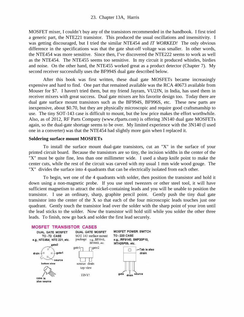
After this book was first written, these dual gate MOSFETs became increasingly expensive and hard to find. One part that remained available was the RCA 40673 available from Mouser for $7. I haven't tried them, but my friend Jayram, VU2JN, in India, has used them in receiver mixers with great success. Dual gate mixers are his favorite design too. Today there are dual gate surface mount transistors such as the BF994S, BF996S, etc. These new parts are inexpensive, about $0.70, but they are physically microscopic and require good craftsmanship to use. The tiny SOT-143 case is difficult to mount, but the low price makes the effort worthwhile. Also, as of 2012, RF Parts Company (www.rfparts.com) is offering 3N140 dual gate MOSFETs again, so the dual-gate shortage seems to be over. My limited experience with the 3N140 (I used one in a converter) was that the NTE454 had slightly more gain when I replaced it.
Soldering surface mount MOSFETs
To install the surface mount dual-gate transistors, cut an "X" in the surface of your printed circuit board. Because the transistors are so tiny, the incision widths in the center of the "X" must be quite fine, less than one millimeter wide. I used a sharp knife point to make the center cuts, while the rest of the circuit was carved with my usual 1 mm wide wood gouge. The "X" divides the surface into 4 quadrants that can be electrically isolated from each other.
To begin, wet one of the 4 quadrants with solder, then position the transistor and hold it down using a non-magnetic probe. If you use steel tweezers or other steel tool, it will have sufficient magnetism to attract the nickel-containing leads and you will be unable to position the transistor. I use an ordinary, sharp, graphite pencil point. Gently push the tiny dual gate transistor into the center of the X so that each of the four microscopic leads touches just one quadrant. Gently touch the transistor lead over the solder with the sharp point of your iron until the lead sticks to the solder. Now the transistor will hold still while you solder the other three leads. To finish, now go back and solder the first lead securely.
24. Chapter 13A, Harris
How much VFO drive is needed?
Reading up on mixers, I learned that mixers are only happy when they receive the exact input levels. That’s why I put a pot on my VFO drive to inject the optimum level. As I turn up the VFO drive to the mixer the output signal strength rises abruptly then levels off. Higher levels of VFO contribute only slightly more gain, but much more noise. I adjust the VFO input to where the gain first begins to level off. My VFOs are designed to work into a 500 ohm load, hence the 500 ohm pot on the input. As you can see from the plot of the 80 meter preselector response, the sensitivity of the 80 meter core receiver should peak anywhere within the 80 meter band when tuned with the large variable capacitor.
The need for mixers to have ideal VFO and signal levels explains why most modern transceivers have input attenuators so that they can be adjusted to tolerate strong signals. I got a QSL card from a guy who wrote, “Sorry about the 529 signal report. After we signed off, I discovered I had the attenuator on.” As mentioned earlier, the 80 meter preselector filter may be deliberately mistuned so that it acts as an attenuator to limit signal strength.
Note: Reception on 80 meters and 160 meters is best with a tuned transmatch
By accident I discovered that reception on the two lowest HF bands is much better when the receiver is sharing the antenna with the transmitter and the antenna is tuned with one of the antenna couplers described in chapter 9. In my neighborhood at least, the signals from the local AM radio stations are so strong that they tend to overwhelm the 80 meter mixer. This results in a lack of audible signals on 80 and 160. I didn't realize I had a problem because I wasn't hearing the AM stations in the headphones. However, when I tuned up the transmatch, suddenly numerous ham signals appeared. The obvious conclusion is that my first receiver preselector filters were not selective enough. Even my old Collins R388 receiver is greatly improved by a tuned antenna coupler.
A JFET mixer
In the event that you need a substitute design, here is a JFET circuit that works but, in my opinion, isn't as sensitive. It is practically the same circuit, but instead of introducing the local oscillator signal into a separate gate, it is introduced across the source resistor. Surprisingly the optimum local oscillator signal input level for this circuit is only about 1 volt peak-to-peak. For this reason the signal is first passed through a 500 ohm pot. I would have expected that, for a circuit like this, the optimum peak voltage would have approached the supply voltage so that the transistor would be entirely turned on and off. Apparently the answer is that this is a depletion type FET that is already half turned on with no bias. Consequently, it doesn't take much drive to turn it either full on or full off.

25. Chapter 13A, Harris
I have used untuned, broadband versions of both these mixer circuits and they are sufficiently sensitive. However, in the second receiver, the untuned versions had more birdies. This may be because my converters in the 2nd receiver had more gain and presented the mixer with more signals to intermix and produce birdies. Understanding all these variables is a challenge!
Crystal filters and BFOs
Crystal IF filters give you the selectivity you will need for working CW stations. They eliminate interference from nearby stations and also eliminate a great deal of the atmospheric noise. The output from the superhetrodyne mixer is a weak, broadband IF frequency signal that needs amplification and filtering before it is ready to be detected. The bandpass filtering is usually done right after the mixer.
Location of crystal filters in a superhetrodyne
The filter could be a "mechanical filter" if you are using a low frequency IF like 455 KHz. But if your IF is 9.0 MHz like mine, then you’ll need one or more crystal filters. Before I describe building crystal filters, I’ll discuss the Beat Frequency Oscillator (BFO). You may need the BFO as a tool to select the crystals for your filters.
The Beat Frequency Oscillator (BFO)
A beat frequency oscillator is an RF oscillator that operates on the intermediate frequency of a superhetrodyne. The BFO sinewave mixes with the IF signal to make CW and single sideband transmissions audible and/ or understandable. Using a simple rectifier detector, (like a crystal set) but without the BFO, CW signals would be inaudible or just thumping noises at best. Single sideband phone would be unintelligible “Donald Duck” sounds. In single sideband the

26. Chapter 13A, Harris
transmitter filters out the basic carrier frequency leaving just one of the modulation sidebands. The BFO serves to restore the carrier sinewave, in effect returning the sideband signal to its original amplitude modulation.
During detection, the audio signal passed on to the loudspeaker is the difference between the IF frequency and the BFO frequency. For example, suppose while listening to CW signals, the IF frequency is 9.000,000 MHz. The BFO frequency might be 9.000,700 MHz. What you hear in your headphones is a musical tone of the difference frequency, 700 Hz. If that pitch sounds unpleasant to you, adjust the BFO frequency to say 9.000,500 MHz to produce a musical tone of 500 Hz. For the musical tone to stay constant, the BFO oscillator must be quite stable. Therefore, we use a crystal oscillator and pull the frequency up or down using a variable capacitor, just like we did in the crystal controlled QRP in chapter 6.
This BFO is taken directly from the W7ZOI and K5IRK receiver in the 1986 ARRL Handbook. Its unusual feature is that its DC power supply rides on the same line as the RF output. This makes it easy to install the BFO in a little metal box up on the front panel remote from the main receiver board. A variable capacitor on the front panel “pulls” the BFO crystal frequency above and below the nominal frequency. The BFO, together with the crystal filter, allow you select upper or lower sidebands.
The Beat Frequency Oscillator (BFO) module in the second receiver
The BFO is connected to the main board with a length of thin coax jumper cable. If you wish to use this oscillator for matching 9 MHz crystals for filters, I suggest you install the BFO

27. Chapter 13A, Harris
crystal in a small IC or transistor socket. Also, you will need to hold the variable capacitor capacitance constant so you can compare the natural resonant frequency of one crystal with another. My solution was to build a separate simple, untuned crystal oscillator just for the purpose of testing random frequency crystals. In other words, the oscillator LC circuit was replaced with an RF choke so that only the crystal resonance determines the frequency.
The BFO frequency tuning range should extend above and below the bandpass of your crystal filters. When the BFO frequency is below the center of the filter bandpass, you are listening to the upper sideband. When the BFO is tuned above the filter bandpass, you’re hearing the lower sideband. Adjusted for the upper sideband, tuning down the CW band will cause the whistle pitch of a signal to start high, drop down to a low pitch, and then disappear. Adjusted for the lower sideband, tuning down the band will cause the pitch to start low then climb up high and disappear. Consequently, it is important to calibrate the BFO tuning knob so that you will know when you are listening to upper or lower sideband. I calibrated mine as Hertz above and below the 9 MHz IF frequency.
For example, set the BFO to the center of the filter bandpass, 9,000,000 Hz. When you tune past a signal, the tone will start at a medium pitch, drop to a low pitch, briefly become inaudible, then climb back up to medium pitch and disappear. I find that the center, zero Hz offset, is best for tuning in sideband signals. As you tune slowly past the signal, the pitch of the distorted speech will drop and the speech will suddenly become intelligible, or even high fidelity. If you set the BFO to the upper or lower sideband, the speech doesn't always become understandable as you tune past.
Ladder filters
Building crystal filters was easy, once I figured out how. Most commercial transceivers use modular crystal filters that have specific bandwidths and are sealed in little cans, something like an integrated circuit. I made my filters from discrete crystals.
One, two and three crystal “ladder filters”
A ladder filter is just two or more crystals in series with capacitors bypassed to ground at the nodes. Think of a crystal as an extremely precise, stable, series LC circuit tuned to the desired frequency. Signals on the exact frequency are passed with little attenuation, while signals off frequency see the crystal as a high resistance or as a very tiny series capacitor. The bandpass width is inversely proportional to the number of crystals and the capacitance to ground. In general, the lower the capacitance on the nodes, the wider the bandwidth. Large capacitors, like 50 ohms reactance, will give narrow bandwidths and higher attenuation. Long “ladders” of course produce even narrower bandwidths and more attenuation. If all the crystals are identical, there will be little attenuation of the center frequency while the “skirt attenuation” on either side
28. Chapter 13A, Harris
of the peak passband becomes steeper and steeper as more crystals are added.
Crystal filters with two or three crystals are selective enough for “CW after dinner.” By that I mean you can work the busy CW bands early in the evening with adequate signal separation. A single crystal filter made from just one 9 MHz crystal is good for single sideband phone (SSB). With two or more crystals the bandwidth becomes so narrow that SSB is often unintelligible. With strong CW signals and lots of QRM (interference from other stations), triple or quadruple crystal ladders are extremely useful. If you tune down to the bottom of 20 meters in the evening, you’ll usually hear a cacophony of CW stations all trying to work the same 5 or 6 DX stations in exotic countries. With only one crystal switched in, you’ll hear practically everyone at once. Switch in two and three crystals and suddenly, you’re not only listening to one clear station, much of the background noise has gone too.
How many crystals can you use in a ladder?
One limit on how many crystals you can use in series depends on the precision with which you match the crystals. I didn’t match my first set of filters and they produced more attenuation than filtering. I then proceeded to waste time getting more gain out of my IF amplifier. Then, after I achieved the gain, the selectivity wasn’t much better than single crystals. Finally, I tested my crystals one by one by putting them in my test crystal oscillator and measuring the frequency with a frequency counter.
I didn’t expect that the frequency filtering characteristics would be exactly the same frequency as when the crystal is used in an oscillator. However, I figured I could at least select sets of crystals that were similar. When I ran them in the oscillator, I was shocked to discover that the crystals were as much as 2.5 KHz different! No wonder they worked so poorly. I had put 9.001 MHz crystals in series with 9.003 MHz crystals. I had built a "crystal barrier,” rather than a crystal filter.
Luckily I had bought twenty 9.000 MHz microprocessor crystals. That sounds extravagant, but they’re $0.54 each at Digi-Key or Mouser. I just noticed that Jameco sells 9 MHz crystals for $2.20 for 10 crystals! The world is rapidly changing - often for the better! Because I had a wide selection of 9.000 MHz crystals, I was able to match up two crystals that were within a few Hz of each other. And I was also able to match up a group of 3 crystals that were within 10 Hz. This time when I put matched crystals in my ladders, the improvement was dramatic. When I switched from a single crystal to a double crystal, the signal strength barely decreased. With three crystals, the signal strength just dropped slightly more. The last batch of 9 MHz crystals I bought in 2012 were from Citizen crystal company and were extremely close in frequency. Matching multiple crystals within a few Hz was easy.
Another limit on the number of crystals in a filter is the shielding and RF isolation between the mixer and the IF amplifier. If the shielding and DC power filtering is poor, your IF amplifier will “hear” the signal from the mixer without the signals ever passing through the crystal filters. In my receivers, 5- or 6-crystal ladders aren’t worth building.
29. Chapter 13A, Harris
Switch in your filters with a rotary switch
I first built my filters as “plug-ins,” but I soon discovered it was too hard to change them in the middle of a QSO (conversation). Eventually I wired them to a rotary switch in a shielded box. As I became more experienced with using the filters, I began to use the triple filter more and more. Finally I built a quadruple filter and now I use it routinely. I find it works well with the S meter (strength meter) as a way to tune my transmitter to zero beat with another ham’s signal. I just sweep my transmitter VFO across the band until the S meter jumps up to maximum. This occurs when the transmitter VFO frequency converted into the IF matches the frequency of the four matched crystals. The offset of the BFO and the tone of the Morse code signal take care of themselves. That is, if the fellow is on the upper sideband, then the S meter only responds to my VFO when I am on the same BFO offset that he is using. This happens because only one sideband is audible at a time with 3- or 4-crystal ladder filters. Don't forget to add a fifth position on your rotary switch for no filter at all - just a short. This position offers a wide bandwidth and is hi-fidelity for AM music and FM signals.
The crystal filters in my second receiver. The rotary switch selects either a simple short circuit or 1, 2, 3 or 4 crystals. Notice that the cases of the crystals are soldered to bare wires which in turn are soldered to ground. I read in "Homebrewer Blog" that this technique is supposed to prevent capacitive coupling around the crystal - they called it "blow-by." The filters worked fine without it and (maybe) there was a slight improvement in noise levels after I added the grounds. I would have needed precision calibrated equipment to prove that the improvement was real, but grounding the cases certainly didn't hurt performance. I suggest that you check out the filters without the grounds first, being sure that they have no shorts or other problems.

30. Chapter 13A, Harris
"Zero" crystal filters
If you select your filters with a rotary switch, don't leave out the "zero filter" or short circuit capability. That is, the output of the 80 meter mixer is connected directly to the IF amplifiers. For a long time I simply always used a crystal filter - one crystal for SSB and 2 or more crystals for CW. Eventually it dawned on me that my best sensitivity was with no crystal filters. Yes, this configuration is quite noisy because the resulting bandwidth is so wide. However, when used with an audio filter like the one described in chapter 13B, extremely weak CW signals can often be extracted out from under the noise. Weak CW stations that are inaudible with a crystal filter or obscured by the noise with no crystal filter can often be heard and copied.
Some fellows in my ham club occasionally go on "DXpeditions" to remote islands. They tell me that one exotic aspect of being the DX guy is that, in the far reaches of the Pacific Ocean, there is often essentially zero noise. If they gave honest signal reports, they would frequently be sending "RST 509" or, on SSB, "Q-5 S-zero." They often hear perfectly clear signals with the S-meter literally reading zero. So if you live in a remote location, you may find zero filtering your most useful setting. Those of us in cities aren't so lucky.
Series and parallel cut “XTALS”
There are two kinds of ordinary crystals, series and parallel cut. As I understand it, the difference is the oscillator circuit for which they are designed to be used. For example, a series-type crystal is intended to be used in series with a specific capacitance in an oscillator. When this exact capacitance is used, it will oscillate at the rated frequency, for example, 9.000 MHz. In contrast, if you use a parallel cut crystal in the same circuit, it might oscillate at 9.004 MHz. You may use either kind of crystal, but your filter frequency may not be exactly 9.000 MHz.
IF gain and signal to noise ratio
As explained earlier, mixers make static-like noise that has nothing to do with signals entering from the antenna. No matter how well a mixer is designed and driven, it will always generate a low level of hissing noise. When listening to very weak signals, the desired signal will sometimes be about as strong as the mixer noise. The trouble with IF amplifiers is that they seem to amplify the mixer noise more than the weak signals. Consequently, when listening to very weak signals, the IF gain control should be turned down as LOW as possible and the audio gain should be turned up quite high to compensate. In the direct coupled receiver (chapter 7) the mixer is followed by an audio amplifier - there are no IF amplifiers. A direct coupled receiver works extremely well for weak signals and now I understand why: There is no IF!
In contrast to listening to weak CW signals, when using an FM detector the atmospheric and mixer noise is eliminated by amplifying the FM voice signal many, many times using several IF amplifiers in series. This seems to be a paradox. I suspect that to receive any FM audio signal, it must first be stronger than the mixer noise. FM detection is discussed in the next chapter, 13B.
Extra IF gain to compensate for crystal filter attenuation
In my first receiver, I used a broadband “optional” amplifier shown below to compensate for the attenuation of the crystal filters. Because I wasn't sure it was needed, I built the amplifier
31. Chapter 13A, Harris
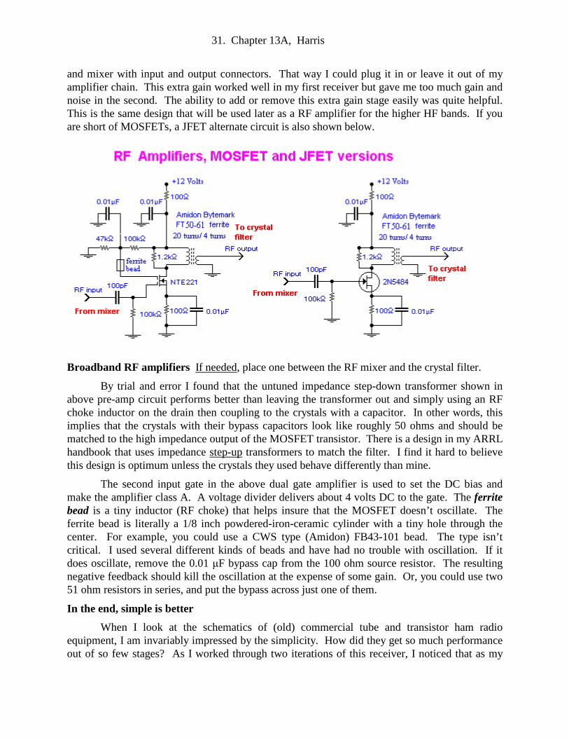
and mixer with input and output connectors. That way I could plug it in or leave it out of my amplifier chain. This extra gain worked well in my first receiver but gave me too much gain and noise in the second. The ability to add or remove this extra gain stage easily was quite helpful. This is the same design that will be used later as a RF amplifier for the higher HF bands. If you are short of MOSFETs, a JFET alternate circuit is also shown below.
Broadband RF amplifiers If needed, place one between the RF mixer and the crystal filter.
By trial and error I found that the untuned impedance step-down transformer shown in above pre-amp circuit performs better than leaving the transformer out and simply using an RF choke inductor on the drain then coupling to the crystals with a capacitor. In other words, this implies that the crystals with their bypass capacitors look like roughly 50 ohms and should be matched to the high impedance output of the MOSFET transistor. There is a design in my ARRL handbook that uses impedance step-up transformers to match the filter. I find it hard to believe this design is optimum unless the crystals they used behave differently than mine.
The second input gate in the above dual gate amplifier is used to set the DC bias and make the amplifier class A. A voltage divider delivers about 4 volts DC to the gate. The ferrite bead is a tiny inductor (RF choke) that helps insure that the MOSFET doesn’t oscillate. The ferrite bead is literally a 1/8 inch powdered-iron-ceramic cylinder with a tiny hole through the center. For example, you could use a CWS type (Amidon) FB43-101 bead. The type isn’t critical. I used several different kinds of beads and have had no trouble with oscillation. If it does oscillate, remove the 0.01 µF bypass cap from the 100 ohm source resistor. The resulting negative feedback should kill the oscillation at the expense of some gain. Or, you could use two 51 ohm resistors in series, and put the bypass across just one of them.
In the end, simple is better
When I look at the schematics of (old) commercial tube and transistor ham radio equipment, I am invariably impressed by the simplicity. How did they get so much performance out of so few stages? As I worked through two iterations of this receiver, I noticed that as my
32. Chapter 13A, Harris
circuits evolved and my understanding grew, I needed fewer stages and parts to accomplish the same goals. Moreover, problems that seemed unavoidable, like birdies and motorboating IF strips, have melted away. So, build your extra gain stage, but be sure you can easily bypass it if and when you discover that it does more harm than good.
The IF amplifier
The IF amplifier and the mixer combination are tricky parts of a superhetrodyne. It’s a high-Q (sharply resonant) amplifier that must handle signals with a range of 100 dB or more without oscillation or noise. This is a huge dynamic range. The gain on the IF amplifier stages should be adjustable using an IF gain control. Too much gain and you will have noise and squeals. Too little gain and you can’t hear weak DX stations.
Oscillations in an IF amplifier come in several flavors. As you tune the LC circuit of an IF amplifier stage you will hear squeals, harsh roaring, silent dead spots and gentle static. The setting that brings in the loudest signals is surprisingly noise free. The first time I turned on my receiver, I quickly learned that most of the receiver noise is coming from the mixer and IF amplifiers, not from the outside world. The noise comes from a maladjusted mixer or too much IF amplifier gain. Even the best mixers and IF strips have some noise. Disconnect the antenna from your best receiver and turn up the gain: See? There is still audible static. It turns out that any warm resistor makes static-like noise. I've heard that if you bathe a circuit in liquid helium, it gets really quiet - the thermionic noise goes away. As an experiment, I tried spraying my mixer and IF with freeze spray. The noise didn't improve, but it did reveal a cold solder joint! I've also read that noise nearly always originates in the mixer and that the noise in an FET is nearly always weaker than the atmospheric noise. I guess sometimes signals are just down in the noise and there is little you can do except use a better, more directional antenna.
Although I was able to tune up my 80 meter receiver using a signal generator, real 80 meter ham signals worked the best for me. There is no point in simulations when you have the real thing. Unfortunately 80 meters may be dead during the day. During the summer, 80 may not be so hot in the evening either. As a result, you might consider building a converter for 20 meters early in the project. (See Chapter 13B). For most of the 11 year sunspot cycle 20 meters usually has signals at any time, day or night, all year long. Since your 80 meter receiver may not yet be working, you can tune up your converter by feeding the output into a commercial receiver tuned to 80 meters. Then, after you have the converter working, you’ll be confident that there are lots of real signals for your 80 meter receiver to hear.
A dual-gate MOSFET IF amplifier
My first versions of the IF amplifier used dual gate MOSFET amplifiers, similar to the crystal filter preamplifier described earlier. The gain of each MOSFET transistor can be controlled by varying the DC bias on one of the two control gates. This control voltage can be generated by either the IF gain knob or by the automatic gain control circuit. In short, the dual gate MOSFET looks ideal for IF stages. Unfortunately, I had lots of trouble with squeals and noise.
With struggle, I eventually managed to get the dual-gate version working in my first receiver. It consisted of two dual-gate tuned amplifiers in series. Each amp was similar to the dual gate amplifier on the previous page. Instead of the fixed 4 volt bias on the second gate,
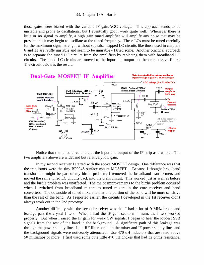
33. Chapter 13A, Harris
those gates were biased with the variable IF gain/AGC voltage. This approach tends to be unstable and prone to oscillations, but I eventually got it work quite well. Whenever there is little or no signal to amplify, a high gain tuned amplifier will amplify any noise that may be present and it may begin to oscillate at the tuned frequency. These LCs must be tuned carefully for the maximum signal strength without squeals. Tapped LC circuits like those used in chapters 6 and 11 are really unstable and seem to be unusable - I tried some. Another practical approach is to separate the tuned LC circuits from the amplifiers by replacing them with broadband LC circuits. The tuned LC circuits are moved to the input and output and become passive filters. The circuit below is the result.
Notice that the tuned circuits are at the input and output of the IF strip as a whole. The two amplifiers above are wideband but relatively low gain.
In my second receiver I started with the above MOSFET design. One difference was that the transistors were the tiny BF994S surface mount MOSFETs. Because I thought broadband transformers might be part of my birdie problem, I removed the broadband transformers and moved the same tuned LC circuits back into the drain circuit. This worked just as well as before and the birdie problem was unaffected. The major improvements to the birdie problem occurred when I switched from broadband mixers to tuned mixers in the core receiver and band converters. The downside of tuned mixers is that one portion of the band will be more sensitive than the rest of the band. As I reported earlier, the circuits I developed in the 1st receiver didn't always work out in the 2nd prototype.
Another difficulty with the second receiver was that I had a lot of 9 MHz broadband leakage past the crystal filters. When I had the IF gain set to minimum, the filters worked properly. But when I raised the IF gain for weak CW signals, I began to hear the loudest SSB signals from the rest of the band in the background. A significant path of this leakage was through the power supply line. I put RF filters on both the mixer and IF power supply lines and the background signals were noticeably attenuated. Use 470 uH inductors that are rated above 50 milliamps or more. I first used some cute little 470 uH chokes that had 32 ohms resistance.

34. Chapter 13A, Harris
They burned out quickly. The slightest momentary short with a voltage probe destroyed them. I replaced them with larger chokes with 2 ohms resistance and have had no further trouble.
Cascode amplifiers - variable gain with constant Q
I had heard of cascode amplifiers but didn’t have a clue why they were wonderful. I had already built two other IF strips before I settled on the circuit shown below. Reading in an old handbook, I spotted the IF amplifier shown. The handbook said that simple transistor amplifiers were poor for IF amplifiers because, when you try to change the gain of a single transistor, the Q of the output tank circuit changes and you get squeals and noise. “Yes!! Yes!!” I cheered. “That’s my problem!” The next circuit uses two (cheap) bipolar transistors in each stage in a “cascode” configuration and seems to cure this difficulty.
The input transistor is wired as an ordinary grounded emitter amplifier with its high input impedance. The clever part is that the second transistor is wired to the first in a grounded base configuration. This gives the amplifier a super-high output impedance which supposedly makes it immune to changing the DC bias on the first stage. Besides, the phrase “cascode amplifiers” sounded cool and I wanted to use some. This cascode amplifier worked well for me. However, after I swapped my two mixer/IF modules back and forth several times, I eventually decided that the original dual gate IF amplifier module worked slightly better - in my first receiver.
In my 2nd receiver, I started out with the dual-gate MOSFET design. First I unplugged the old IF module from my first receiver to re-examine the circuit and confirm my diagram. What a bird's nest! By the time I had the first prototype working well, the circuit was almost impossible to unravel and copy. Consequently I built the MOSFET mixer and IF strip shown earlier. They worked OK for strong signals but had too much noise and multiple birdies. I know that these same circuits worked much better in the first receiver, but I don't know why.
In the 2nd receiver I used my usual NTE454 MOSFET mixer circuit. I plugged in the cascode amplifier shown above and ... Voila! It works like a champ - low noise and no obvious

35. Chapter 13A, Harris
birdies. That's why I build everything with interchangeable modules and I don't scrap them until I'm convinced they are no longer useful. Because I no longer had a significant birdie problem, I went back and converted the mixer that covers the band converters back to broadband without any disadvantage.
How to tune an IF amplifier
When you first turn on your 80 meter receiver module, there will be several modules with variable capacitors and pots that all need to be adjusted. Let's assume that you have checked out the VFO and it is providing enough voltage sinewave to drive your particular mixer. You should also have a look at the waveform of your BFO after it has arrived at the receiver module. It should be a smooth, clean sinewave. A clean sinewave is more important than high amplitude. You may want to readjust the trimmer capacitor on the BFO oscillator for the best waveform.
To align the IF you could just twiddle pots and trimmers and hope you hit a favorable combination of settings. I've tried that ... it doesn't work very well. First, clip an oscilloscope probe onto the output capacitor going from the IF amplifier to the product detector. At this point your BFO comes to your rescue. Clip a test lead onto the connector where the BFO plugs into the 80 meter receiver board. This signal line also has 12 volts riding on it, so connect the other end of the test lead to a small capacitor, say 20 pF. This will filter out the DC. Use the other end of the capacitor as a signal probe to inject a 9 MHz test signal into your IF amplifiers. Since the oscilloscope probe is at the output of the IF, start by aligning the trimmer and input pot of the last amplifier.
Next move the BFO test signal down to the input of the first amplifier and adjust the trimmer capacitor and input trim pot. Peak the 9 MHz signal at the output as before. Now remove the BFO signal test probe but leave the oscilloscope probe in place.
At this point, if there are strong 80 meter signals at the input to the mixer, you should begin to be able to hear them. Now slightly adjust each stage carefully for maximum sound level. Notice that maximum sound level is not the same setting as the maximum 9 MHz carrier in the output. It surprised me that maximum sound level was not the same as maximum 9 MHz sinewave.
Too much IF gain and loss of IF selectivity
If you have done everything above and have the IF working reasonably well, it may have two annoying limitations: First, the IF strip will tend to oscillate, especially when the crystal filter is set for multiple crystals. This is because the AGC raises the gain to compensate for the extra signal loss of multiple crystals. To adjust for this, you can detune the first IF amplifier to either side of the oscillation point until it stops oscillating, even with the quadruple crystal filter. Also, you can decrease the VFO drive to your mixer lowering the level of the 9 MHz IF signals. Finally, you can just live with it by decreasing the IF gain until the oscillation blocking stops and the signals are audible.
The second glitch is that strong signals elsewhere on the band may appear in your headphones. This happens even though you may be tuned to the opposite end of the band. On 20 meters there are often kilowatt SSB stations with enormous directional antennas pointed right at you. Even when you are listening to CW 250 KHz below them, you can still hear their Donald Duck squawking in the background. On 30 meters, you may hear 31 meter band religious
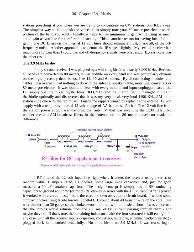
36. Chapter 13A, Harris
stations preaching at you when you are trying to concentrate on CW stations, 300 KHz away. The simplest way to extinguish the voices is to simply tune your 80 meter preselector to the portion of the band you want. Finally, it helps to use minimum IF gain while using as much audio gain as you like for comfortable listening. This is another reason for having lots of audio gain. The DC filters on the internal 12 volt lines should eliminate most, if not all, of the off- frequency noise. Another approach is to detune the IF stages slightly. My second receiver had much more IF gain than I could use and off-frequency signals were one result. Excess noise was the other result.
The 3.9 MHz birdie
In my second receiver I was plagued by a whistling birdie at exactly 3.900 MHz. Because all bands are converted to 80 meters, it was audible on every band and was particularly obvious on the high, presently dead bands, like 12, 10 and 6 meters. By disconnecting modules and cables I discovered it had nothing to do with the antenna, speaker cable, mute line, converters or 80 meter preselector. It was loud and clear with every module and input unplugged except the DC supply line, the mixer, crystal filter, BFO, VFO and the IF amplifier. I managed to tune in the birdie optimally and discovered that it was my very local, very loud 1190 KHz AM radio station - the one with the rap music. I made the rappers vanish by replacing the external 12 volt supply with a temporary internal 12 volt kludge of AA batteries. Ah-ha! The 12 volt line from the station power supply was the principle "antenna" that was receiving the 1190 KHz. No wonder the anti-AM-broadcast filters in the antenna or the 80 meter preselector made no difference!
I RF filtered the 12 volt input line right where it enters the receiver using a series of random value, 1 ampere rated, RF chokes, some large mica capacitors and, just for good measure, a 10 µF tantalum capacitor. The design concept is simply lots of RF-conducting capacitors to ground and three (or more) RF chokes in series with the DC current. After I proved it worked with a crude mess, I built the circuit shown above on a circuit board. I wound some compact chokes using ferrite toroids, FT50-43. I wound about 40 turns of wire on the core. Use wire thicker than 30 gauge so the chokes won't burn out with a transient short. I was concerned that the toroids would saturate from the 200 ma. of DC current passing through them - and maybe they do! If that's true, the remaining inductance with the iron saturated is still enough. In any case, with all the receiver inputs - (speaker, converters, mute line, antenna, headphones etc.) - plugged back in it worked beautifully. No more birdie on 3.9 MHz! It was reassuring to
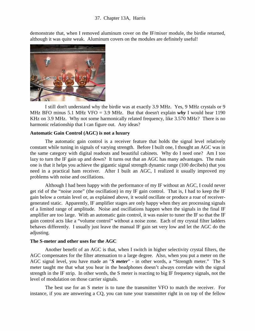
37. Chapter 13A, Harris
demonstrate that, when I removed aluminum cover on the IF/mixer module, the birdie returned, although it was quite weak. Aluminum covers on the modules are definitely useful!
I still don't understand why the birdie was at exactly 3.9 MHz. Yes, 9 MHz crystals or 9 MHz BFO minus 5.1 MHz VFO = 3.9 MHz. But that doesn't explain why I would hear 1190 KHz on 3.9 MHz. Why not some harmonically related frequency, like 3.570 MHz? There is no harmonic relationship that I can figure out. Any ideas?
Automatic Gain Control (AGC) is not a luxury
The automatic gain control is a receiver feature that holds the signal level relatively constant while tuning in signals of varying strength. Before I built one, I thought an AGC was in the same category with digital readouts and beautiful cabinets. Why do I need one? Am I too lazy to turn the IF gain up and down? It turns out that an AGC has many advantages. The main one is that it helps you achieve the gigantic signal strength dynamic range (100 decibels) that you need in a practical ham receiver. After I built an AGC, I realized it usually improved my problems with noise and oscillations.
Although I had been happy with the performance of my IF without an AGC, I could never get rid of the “noise zone” (the oscillation) in my IF gain control. That is, I had to keep the IF gain below a certain level or, as explained above, it would oscillate or produce a roar of receiver-generated static. Apparently, IF amplifier stages are only happy when they are processing signals of a limited range of amplitude. Noise and oscillations happen when the signals in the final IF amplifier are too large. With an automatic gain control, it was easier to tuner the IF so that the IF gain control acts like a “volume control” without a noise zone. Each of my crystal filter ladders behaves differently. I usually just leave the manual IF gain set very low and let the AGC do the adjusting.
The S-meter and other uses for the AGC
Another benefit of an AGC is that, when I switch in higher selectivity crystal filters, the AGC compensates for the filter attenuation to a large degree. Also, when you put a meter on the AGC signal level, you have made an "S meter" - in other words, a “Strength meter.” The S meter taught me that what you hear in the headphones doesn’t always correlate with the signal strength in the IF strip. In other words, the S meter is reacting to big IF frequency signals, not the level of modulation on those carrier signals.
The best use for an S meter is to tune the transmitter VFO to match the receiver. For instance, if you are answering a CQ, you can tune your transmitter right in on top of the fellow

38. Chapter 13A, Harris
you want to call. First, you need to switch in a 3- or 4-crystal filter. Then, as you slew your transmitter VFO across the frequency, the S meter needle will soar when you are lined up right on top of him. If you don't use this technique, “zero beating” the VFO is time consuming. Modern transceivers don’t have this synchronization problem because the receiver and transmitter are using the same VFO.
I originally used a digital bargraph S meter that looks very racey. Unfortunately, like virtually everything digital, it makes a hissing radio noise when it changes level and I don’t need that. I tried hard to filter the bargraph circuit, but as usual, I couldn’t get rid of the hiss. I finally replaced it with an old-fashioned analog meter and the noise vanished. I talked to a guy who designs cell phones for a living and asked about interference. He tells me they custom design their many layered chips so that digital noise is contained INSIDE shield layers within the chips. No pathways that carry HF digital noise are allowed access to the outside world. They have to use X-rays to check the chip architecture because there can be no external access to the noisy digital signals - definitely not basement technology.
Automatic Gain Control (AGC)
An AGC works by sampling the output level of the last IF amplifier stage. Signals are detected like a crystal set using a diode and averaged with a capacitor to produce a DC level proportional to the IF signal strength. This DC level is then amplified and used to bias the IF amplifiers. For example, the above circuit can deliver the positive voltage bias on IF amplifier stages made from dual gate MOSFETs. Or if the IF amplifiers are made from bipolar transistors, the same circuit can put Class A bias current into the bases of the transistors. For big signals, the AGC automatically turns off the bias and runs the transistors “Class C.” When signals become weak, the bases are biased “ON” so that the signals don’t have to exceed the 0.6 volt input barrier.
I used a one milliampere meter in the first receiver, but it rarely registers with strong signals from the antenna. It does swing full scale with my transmitter SPOT signals. I used a 100 microampere meter in the 2nd receiver and it is nearly always active with received signals and is often pinned full scale. I don't have the equipment to calibrate it like commercial S-meters. I assume that with a parallel trim pot, the sensitivity could be adjusted to give standard "S values" and "dB over S-9" just like you often hear when hams give SSB phone signal reports.
The product detector
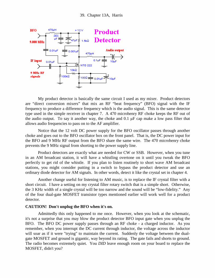
39. Chapter 13A, Harris
My product detector is basically the same circuit I used as my mixer. Product detectors are “direct conversion mixers” that mix an RF “beat frequency” (BFO) signal with the IF frequency to produce a difference frequency which is the audio signal. This is the same detector type used in the simple receiver in chapter 7. A 470 microhenry RF choke keeps the RF out of the audio output. To say it another way, the choke and 0.1 µF cap make a low pass filter that allows audio frequencies to pass on to the AF amplifier.
Notice that the 12 volt DC power supply for the BFO oscillator passes through another choke and goes out to the BFO oscillator box on the front panel. That is, the DC power input for the BFO and 9 MHz RF output from the BFO share the same wire. The 470 microhenry choke prevents the 9 MHz signal from shorting to the power supply line.
Product detectors are exactly what are needed for CW or SSB. However, when you tune in an AM broadcast station, it will have a whistling overtone on it until you tweak the BFO perfectly to get rid of the whistle. If you plan to listen routinely to short wave AM broadcast stations, you might consider putting in a switch to bypass the product detector and use an ordinary diode detector for AM signals. In other words, detect it like the crystal set in chapter 4.
Another change useful for listening to AM music, is to replace the IF crystal filter with a short circuit. I have a setting on my crystal filter rotary switch that is a simple short. Otherwise, the 3 KHz width of a single crystal will be too narrow and the sound will be “low-fidelity.” Any of the four dual-gate MOSFET transistor types mentioned earlier will work well for a product detector.
CAUTION! Don't unplug the BFO when it's on.
Admittedly this only happened to me once. However, when you look at the schematic, it's not a surprise that you may blow the product detector BFO input gate when you unplug the BFO. The BFO DC power supply passes through an RF choke - a charged inductor. As you remember, when you interrupt the DC current through inductor, the voltage across the inductor will soar as if it were "trying" to maintain the current. Suddenly the voltage between the dual-gate MOSFET and ground is gigantic, way beyond its rating. The gate fails and shorts to ground. The radio becomes extremely quiet. You DID leave enough room on your board to replace the MOSFET, didn't you?

40. Chapter 13A, Harris
Here is a JFET version that also works OK.
With product detectors, anything works at least a little
In my experience, receiver RF mixers that produce a quality IF output are extremely finicky and are often plagued with low sensitivity and oscillations up and down the band. In contrast, a product detector is amazingly uncritical. I haven’t tried to make one out of wood shavings or pebbles from the street, but I wouldn’t be surprised if I could still hear signals.
For example, I built a new IF strip and product detector in hopes of improving the noise problem. It worked, but I was slightly disappointed with the sensitivity. I was inspecting my dual gate MOSFET product detector when I realized that I had soldered the MOSFET 90o out of alignment. In other words, the drain was connected to the RF input gate, the source was connected to the drain circuit, and the BFO input was connected to the source. Delighted that I had discovered my problem, I correctly soldered in a new transistor. When built properly, it worked better - but not dramatically better.
In another experiment I disconnected the RF input so that the input to the product detector was just stray coupling from the IF strip. Signals were weak, but it still worked amazingly well! Finally, I disconnected the BFO input. I was relieved to confirm that it no longer tuned and received ham-band signals. Instead it worked like a crystal set and received the loudest signals on or near the ham band input. For example, on 17 meters, it brought in the Deutsche Welle (Radio Germany) loud and clear.
The AF amplifier
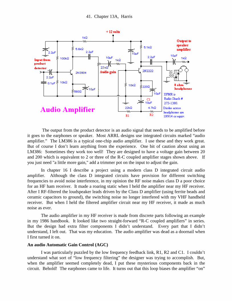
41. Chapter 13A, Harris
The output from the product detector is an audio signal that needs to be amplified before it goes to the earphones or speaker. Most ARRL designs use integrated circuits marked “audio amplifier.” The LM386 is a typical one-chip audio amplifier. I use these and they work great. But of course I don’t learn anything from the experience. One bit of caution about using an LM386: Sometimes they work too well! They are designed to have a voltage gain between 20 and 200 which is equivalent to 2 or three of the R-C coupled amplifier stages shown above. If you just need "a little more gain," add a trimmer pot on the input to adjust the gain.
In chapter 16 I describe a project using a modern class D integrated circuit audio amplifier. Although the class D integrated circuits have provision for different switching frequencies to avoid noise interference, in my opinion the RF noise makes class D a poor choice for an HF ham receiver. It made a roaring static when I held the amplifier near my HF receiver. After I RF-filtered the loudspeaker leads driven by the Class D amplifier (using ferrite beads and ceramic capacitors to ground), the switching noise no longer interfered with my VHF handheld receiver. But when I held the filtered amplifier circuit near my HF receiver, it made as much noise as ever.
The audio amplifier in my HF receiver is made from discrete parts following an example in my 1986 handbook. It looked like two straight-forward “R-C coupled amplifiers” in series. But the design had extra filter components I didn’t understand. Every part that I didn’t understand, I left out. That was my education. The audio amplifier was dead as a doornail when I first turned it on.
An audio Automatic Gain Control (AGC)
I was particularly puzzled by the low frequency feedback link, R1, R2 and C1. I couldn’t understand what sort of “low frequency filtering” the designer was trying to accomplish. But, when the amplifier seemed completely dead, I put these mysterious components back in the circuit. Behold! The earphones came to life. It turns out that this loop biases the amplifier “on”

42. Chapter 13A, Harris
for weak signals and biases it “off” for loud signals. It’s a sort of audio AGC circuit.
Remember that for a bipolar transistor to turn on, the input signal must be greater than 0.6 volts or no current will flow into the base. In a “Class A” amplifier a DC signal is added to the base. This increases the base voltage above 0.6 volts so that it’s always turned on. In this way a class A amplifier can amplify signals much smaller than 0.6 volts. The low frequency feedback adjusts the bias for weak and strong signals. When the signals are weak, the second transistor is turned off, so it’s collector voltage is high and unchanging. This big collector voltage is leaked into C1 to provide a forward bias for its own base, biasing it on and raising the sensitivity. Conversely, when the signals are strong, the collector has a big current flowing but a low average DC voltage from the collector to ground. This lower voltage biases the transistor more “off.”
After you have the whole receiver working, you may decide you need more audio gain. Consequently, it's a good idea to leave room on the PC board to add another stage of audio amplification, just in case. For instance, the 2 stage circuit above is an abbreviated version of the 3 stage audio amplifier in chapter 7.
Protecting your ears from strong signals
This audio amplifier is able to blow your ears off when you encounter a strong signal. Therefore it’s essential to add a clamp circuit to limit the voltage to the headphones to less than about a volt. I first did this with back-to-back 5 volt Zener diodes across the headphone jack. In practice, with sensitive modern 8 ohm headphones, I found that less than one volt peak is plenty of volume for me. Eventually I put in two ordinary silicon 1N914 diodes “shorted” in opposite directions across the headphones. This limits the positive and negative sound peaks to just +/- 0.6 volts and my ears haven’t been blasted since. If it's still louder than you prefer, use Schottky or germanium diodes which will limit peaks to +/- 0.2 volts DC.
How Hi-Fi should it be?
The original W7ZOI/K5IRK circuit was also sprinkled with 0.1 microfarad bypass capacitors as if the designer were trying to kill all higher frequency sounds and shunt most of the audio to ground. Since I was trying to get more gain wherever I could, I left out the bypasses. The amplifier worked well without them, but the sound of the static had an obnoxious, piercing high pitch that irritated my ears. I put the bypasses in and, as I expected, the audio sounded more “bass” and became somewhat weaker. However, getting rid of that piercing, hissing static was well worth the loss of gain. Experiment!
The original design also had no emitter bypass capacitor, the 10 microfarad capacitor across the 220 ohm resistor. Not having this bypass capacitor reduces the gain because some of the audio voltage signal is wasted across the 220 ohm emitter resistor. Since I needed gain, I put in the capacitor and my gain jumped up noticeably. This bypass has no disadvantage that I could detect.
In the second half of this chapter, Chapter 13B, I'll discuss building converters, a speaker driver and other optional features.

43. Chapter 13A, Harris