chapter 14 ring instrumentation and controls
TRANSCRIPT
Chapter 14
Ring Instrumentation and Controls
This chapter describes the technical design of the g-2 cryogenic and vacuum control sys-tem and other process systems supporting the experiment. This control system will be acopy of the typical Siemens S7-400 PLC (Programmable Logic Controller) control systemas deployed by the Fermilab PPD/Mechanical Department. The g-2 cryogenic and vacuumsystem will be located on the Muon campus in the MC1 building and Muon g-2 experimentalhall. This area is classified as ODH Class 0 area and has several large cryogenic and gascomponents. Cryogens include Liquid Helium and Liquid Nitrogen. This cryogenic systemhas approximately 600 electronic input sensing devices and 100 output devices. Input de-vices include temperature sensors, pressure transmitters, vacuum gages, level probes, andstrain gages. Output devices include solenoid valves, control valves, and vacuum valves andpumps. All electronic and electrical control system equipment is air cooled and does notrequire any forced air cooling or water cooling. Cabinet air vents are provided for certaindevices where appropriate. The control system equipment components are all commerciallyavailable products which are UL listed. The cryogenic control system has been designed andwill be built following all the required rules and standards such as the NEC and NFPA 70E.All premises wiring is to be installed by Fermi Electrical contractors and licensed electricians.
14.1 Cryogenic/Vacuum Control System
The G-2 process controls also known as the slow controls will have a Siemens S7-400 PLCwith S7-300 associated I/O modules as the master control system. There will be sub systemscontrolled by other PLCs that will report to the Master PLC. The Master PLC will alsoprovide system data and interlocks to these subordinate PLC systems. The DAQ controlsystem known as MIDAS will also be provided data and interlocks from this S7-400 masterPLC. See the Control System Architecture drawing shown in figure 14.1.
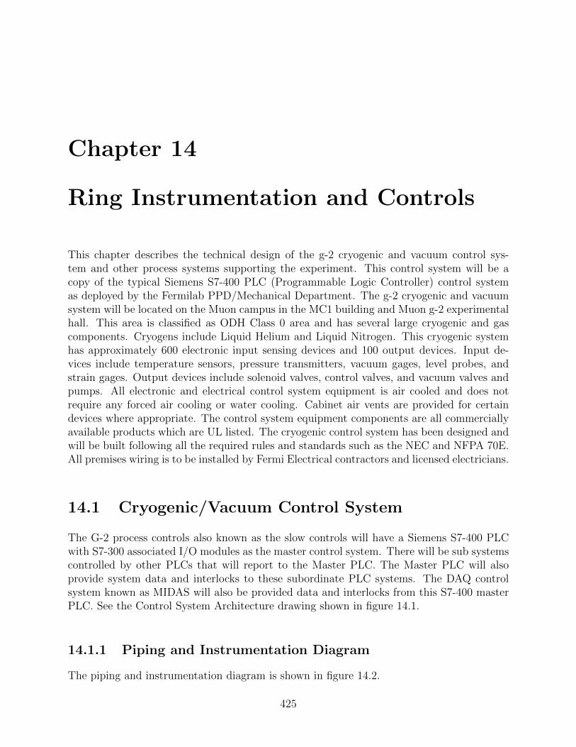
14.1.1 Piping and Instrumentation Diagram
The piping and instrumentation diagram is shown in figure 14.2.
425

426 RING INSTRUMENTATION AND CONTROLS
Figure 14.1: G-2 Controls System Architecture.
14.1.2 Programmable Logic Controller
The g-2 cryogenic/vacuum system will be controlled by a Siemens S7-400 PLC with S7-300associated I/O modules (or equivalent industrial controls system) networked on a Profibus
CHAPTER 14 427
Figure 14.2: The G-2 Piping and Instrumentation Diagram.

428 RING INSTRUMENTATION AND CONTROLS
network. This PLC system will be programmed using the Siemens S7 engineering program-ming software (or equivalent software meeting IEC 61131-3 standard). Siemens S7-400 PLCsystems are currently in use at several Fermilab projects: LAPD, LBNE 35 Ton, SuperCDMS, Microboone, and NML/CMTF.
14.1.3 Instrumentation
The g-2 cryogenic/vacuum system instrumentation will consist of commercial transducers,transmitters, valves, positioners, strain gauges, and thermometers. These commercial deviceswill have conventional signals that conform to the normal PLC module input and outputsignal ranges. The locations of these devices are given in reference [1]. PSIG, PSIA, anddifferential pressures will be measured by commercial transmitters that provide a 4-20 mAsignal when available. A voltage range of 0-10 VDC will be an alternate range. Temperaturewill be measured by a Platinum 100 ohm RTD when possible, because the PLC systemcan read them directly. There are a number of Silicon diodes in the detector which willbe measured by a Lakeshore temperature transmitter that provides a 4-20mA output tothe PLC system. Any Cernox RTDs will also be measured with a Lakeshore temperaturetransmitter that provides a 4-20 mA signal to the PLC.
14.1.4 Strain Gauges
G-2 has strain gauges (full bridge style) mounted on the straps and radial stops, whichare inside the cryostats and so are at cryogenic temperatures. Room temperature straingauges are also mounted on the outer cryostat pushrods. Strain gauges will be used duringcommissioning to make sure that the forces agree with expectation. It is not necessary toread out all these strain gauges during regular experiment operation.
All strain gauges (4 wires per gauge) will be connected to a patch panel in the controlroom. A select subset of strain gauges will be read out with 2 Vishay D4 units, which willbe connected to a Windows PC via USB.1 Each Vishay D4 unit can read out 4 full-bridgestrain gauges. A full description can be found in reference [2].
14.1.5 Vacuum Pump Control
Vacuum Pump stations are used to maintain various vacuum systems. These stations canbe controlled by the Master PLC system using discrete I/O. Each pumping station alsohas isolation control valves. The vacuum pumps for the ring cryostats and beam vacuumchambers are described in tables 14.1.5 and 14.1.5.
The pump station remote control interface is shown in figure 14.3.
14.1.6 Programmable Logic Controller Input/Output
The g-2 cryogenic/vacuum system will be controlled by a Siemens S7-400 PLC with S7-300associated I/O modules (or equivalent industrial controls system) networked on a Profibus
1Any strain gauge can be read out by manually plugging it into one of the Vishay D4 units.

CHAPTER 14 429
Table 14.1: Summary of vacuum pumps for the ring cryostats. The Turbo Molecular Pumps(TMPs) pump helium and air to maintain the cryostat insulating vacuum pressure at lessthan 1E-4 Torr.
Pump Type LocationRoots Blower Lead Pot 1
Backup to Roots Blower Upper 11 PositionTMP Upper Lead Pot 2TMP Upper 7TMP Lower 7TMP Lower 11TMP Outer 7TMP Outer 11TMP Lower 3
Table 14.2: Summary of vacuum pumps for the ring beam vacuum chambers. The TurboMolecular Pumps (TMPs) pump helium and air to maintain the cryostat insulating vacuumpressure at less than 1E-7 Torr.
Pump Type LocationTMP Chamber 6TMP Chamber 12TMP Chamber 8 (contains straw tracker)TMP Chamber 10 (contains straw tracker)TMP Chamber 2 (contains trolley drive)
Cryo Pump Chamber 3Cryo Pump Chamber 9
network. The I/O modules convert digital PLC values to the field instrumentation andvisa-versa. Table 14.1.6 summarizes the input/outputs.
14.1.7 Human Machine Interface
Human Machine Interface (HMI) controls will be provided through GEFANUC’s iFIX soft-ware. iFIX connects to the S7-400 through Private Ethernet using an Industrial GatewayServer (IGS) driver included with the iFix software. iFIX will handle all operator security,computer alarming, and remote operator controls via the PPD-iFIX server. iFIX will alsoprovide historical data through the PPD-iFIX historian. This historical data will be viewablein iFIX picture displays or on the web through the iFIX Proficy portal server. An exampleof an HMI for the LAPD experiment is shown in figure 14.4.

430 RING INSTRUMENTATION AND CONTROLS
Figure 14.3: The Pump Station Remote Control Interface.
14.1.8 Helium Refrigerator Controls
The Helium liquefier system controls were designed and built by the Accelerator Divisioncryogenic department. This control system also consists of a Siemens S7-400 PLC as thecore controller. This system will easily interface with the G-2 experiment master SiemensS7-400. The AD cryo S7-400 and the G-2 S7-400 PLC will share a private network. Thisprivate network will allow PLC variables to be shared in either direction and also allow theiFIX HMI to control the Helium refrigerator components.
14.1.9 System Communication and Data Sharing
Data will need to be shared between multiple systems outside of the Siemens master PLCsystem. There are a number of methods and protocols that allow data sharing such asOPC, MODBUS TCP/IP, SQL, and others. The Helium refrigerator communication will be

CHAPTER 14 431
Table 14.3: Summary of types of input/outputs connections to the PLC
Subsystem 4-20mA0-10 VDCAnaloginputs
SiliconDiodeinputs
RTD(PT100’s)inputs
Discrete(digital)24 VDCinputs
Discrete(digital)24VDCoutputs
24 VDCAnalogoutputs
Magnet Cryo 23 68 10 20 8 7Inflector Cryo 10 10 10 10 10 4Cryostat Vac-uum
10 0 10 40 40 2
ODH 10 0 2 10 6 2LCW/ChilledWater
10 0 10 10 10 4
Storage RingVacuum
7 0 7 30 30 4
Yoke/Pole 10 0 10 10 10 10Tracker 10 0 10 10 10 10DC System 10 0 10 10 10 4Subtotal 100 78 79 150 134 47Total 588
through the private network that links the G-2 Master S7-400 PLC and the AD cryogeniccontrol system S7-400 PLC. The DAQ system HMI is known as MIDAS. The most likelycommunication path between the G-2 Master Siemens S7-400 PLC and MIDAS will be OPCover Ethernet, but SQL is also possible. The magnet DC control system will be run by aBeckhoff CX5000 PLC. The Beckhoff CX 5000 PLC will be linked to the G-2 Master SiemensS7-400 PLC through PROFINET which is an industrial protocol supported by both systems
14.2 Life Safety and System Reliability
ODH System
The ODH system will utilize six MSA O2 heads. Two O2 heads will be located near theceiling of the g-2 experimental hall, with another four O2 sensors located near the floor of thehall. There will be an ODH warning horn and strobe lamp. These will be centrally located inthe hall. There will be two ventilation fans used to maintain the ODH risk class zero statusin the g-2 hall. One fan will exhaust air out of the g-2 hall at the ceiling venting it outside.The second fan will supply fresh air to the building near the floor outside of the rings. Thesefans are controlled by the S7 PLC and can also be run locally using a switch mounted atthe fan controls. The ODH system is hardwired to both fans such that during an ODHalarm both fans run. The O2 Sensors are MSA model A-UltimaX-PL-A-14-03D2-0000-100and have a span of 0-25%. Each O2 sensor is to be wired to an MSA electronic controller

432 RING INSTRUMENTATION AND CONTROLS
Figure 14.4: Human Machine Interface for the LAPD experiment.
which provides an analog output signal wired to the S7 PLC. This MSA electronic unit alsoprovides relays which have three O2 level alarms thresholds, 18.5%, 18%, and 17.5%. Therelay output that is set at 18.5% is wired directly to the ODH warning horns and strobelamps located in MC1 and FIRUS. The MSA electronic unit also provides a trouble relayoutput which is also wired to the PLC and FIRUS. The trouble output is wired in a failsafemanner, such that loss of power or blown fuse to the ODH controls will generate a troublealarm. The MSA equipment is wired directly to its own self-contained control circuitry in itsown enclosure. This self-contained enclosure has its own power supply which is independentof the PLC control system, allowing the ODH system to function independently of the PLCcontrol system. The power for this ODH system comes from a U.P.S. (Uninterruptible PowerSupply).
14.2.1 Uninterruptible Power Supply (U.P.S.)
The control system U.P.S. is to be a commercial unit such as those manufactured by Power-ware. The U.P.S. input power is fed from a premises powered outlet using the U.P.S. inputline cord. This U.P.S. system will be natural gas generator backed. The diesel generator willbe auto start with auto switchover on commercial power loss. There will be other loads onthis generator as well. The U.P.S. has standard outlets located on the rear of the cabinet.An APC surge protector is located on the U.P.S. and its input power cord is plugged into

CHAPTER 14 433
the U.P.S output outlets. All relevant control system loads are plugged into the APC surgeprotector output outlets.
14.2.2 PLC Reliability and Redundancy
Siemens SIMATIC (S7 PLC and ET200M I/O modules) components meet all relevant in-ternational standards and are certified accordingly. Temperature and shock resistance aredefined in the SIMATIC quality guidelines, as are vibration resistance or electromagneticcompatibility. The Siemens S7 PLC system equipment can be redundant at many differentlevels, from the PLC CPU (Hot Backup) to the module and instrument level. We expect tohave the redundancy at the PLC level.

References
[1] Documentation of Instruments in the g-2 Cryostats, g-2 DocDB note 1653.
[2] Strain Gauge Configuration and Cost Estimate, g-2 DocDB note 861.
[3] Electrical Design Standards for Electronics to be used in Experiment Apparatus atFermilab.
[4] EED/Infrastructure Doc. No:H011228A.
434