chapter 15: an easy-build generator. -...
TRANSCRIPT

Chapter 15: An Easy-Build Generator. Many people want a simple project which they can build and which demonstrates free-energy. Let’s see if this need can be met. You must understand that most generators, whether free-energy or conventional energy, are not particularly low-cost to make. For example, if you wanted a device which showed that burning a fuel could propel a vehicle, then building a car could do that, but making a car is not necessarily cheap. However, let’s see what we can manage here. However, please understand that you, and you alone, are responsible for whatever you do. This presentation is NOT an encouragement for you to make or build anything. It is merely some suggestions which you might find helpful if you have already decided to build something. This means that if you injure yourself, neither I nor anyone else is liable in any way. For example, if you are cutting a piece of wood with a saw and are very careless and cut yourself, then you, and only you are responsible for that – you should learn to be more careful. If you drop something heavy on your toe, then you, and only you, are responsible for that. Normally, constructions of this type do not result in any kind of injury, but please be careful if you decide to build. In chapter 2 of the ebook available free from http://www.free-energy-info.tuks.nl there is a rotary generator design by Lawrence Tseung which was built by Mr Tong Po Chi and his colleagues. Being an open and straightforward construction, it has been demonstrate publicly, on many occasions as having 330% efficiency, that is, the output power is 3.3 times greater than the input power. Another way of saying this is to say that it’s Coefficient of Performance is 3.3 (or COP=3.3). Hopefully, we will achieve much better performance than that in this construction. No drawings in this document are to scale. I suggest that we start by replicating the original design, and then apply some modifications step by step in order to raise the output power. The original construction looks like this:
In the version shown above, there are six electrical meters, but those are not necessary and they were included to help when demonstrating the device to members of the public. Built in October 2009, the unit shown has a 600 mm diameter rotor (which is not visible in the photograph). It has 16 permanent magnets mounted on the rotor
15 - 1

rim and 16 air-core coils mounted on the stator, one of which is used as a timing sensor. The coils can be switched to act as either rotor powering coils or as power collecting coils. Initially, power is provided by a small lead-acid battery. The power is applied through the very simple switching style shown in the 1974 patent of Roger Andrews US 3,783,550 where a passing magnet activates the circuit which powers the system. The rotor magnets trigger the operation and the fifteen main coils mounted on the stator can be switched to be either electromagnets pushing the rotor on it’s way, or as energy-gathering coils producing a power output. If you are a skilled constructor of new devices, then please excuse me for making so many constructional suggestions aimed at first-time constructors. The main generator components are like this:
The wooden planks holding the two sides together, are chosen to be wide enough to give stability, and more importantly, to allow space so that three rotors could be mounted on the axle if using multiple rotors is chosen as one of the various upgrade options. The two stator sides are connected together by sixteen lengths of wooden
15 - 2

plank and to a much lesser extent, by the baseboard. The dimensions of all components will be suggested later, but for the time being, let’s concentrate on connecting the stator pieces together properly. Each plank is supplied with a factory cut straight edge top and bottom. The end of the plank supplied has a perfectly square edge, but we have to cut the required length and get a good cut every time. It is easy enough to mark a perfectly square line across the width of the plank, but cutting along that line is not sufficient as the cut needs to be absolutely square as it moves through the thickness of the plank. If the cut isn’t properly square, then that face will not form a good fit against the stator piece and the workmanship will be very inferior. For somebody who does not have a cutting table, it is a very good idea to use a mitre box in order to get a good quality cut:
The width of the mitre box limits the width of the plank which can be used and a common size for the mitre box channel is just over 90 mm. Allowing the box to guide the saw blade without forcing it and sawing gently, produces a properly square cut in the two planes needed. Planed Square Edge timber is available with a width of 89 mm and thickness 38 mm, and that should be suitable:
If we choose to use threaded rod for the axle:
15 - 3

then it is available in various lengths, and while it is perfectly possible to cut it to whatever length is chosen, we might as well pick a 500 mm length and save having to cut a longer length to get what we need. I suggest a 10 mm diameter rod and if the overall length is 500 mm, then the gap between the two stator pieces might be 430 mm and the overall length of timber used would then be 16 x 430 = 6880 mm or 22.5 feet. However, as it is most unlikely that any timber supplied would be exactly a multiple of the 430 mm chosen, then a slightly greater length will be needed and there will be offcuts. One big advantage of using a threaded rod as the axle is that nuts and washers can be used to clamp a rotor exactly square to the axle and then lock nuts used to clamp it permanently in place. The axle needs to be supported in a low-friction bearing and the most readily available type is the sealed ball or roller bearing:
These have a rubber seal to keep dust and dirt out of the grease packed around the ball bearings inside and that spoils the free movement. One way to overcome this has the bearing outer ring clamped stationary and an electric drill used to spin the inner ring until the movement becomes low-friction. A 10 mm inner diameter bearing is often referred to as a type 6200. An alternative method is to remove the rubber seals and remove the grease by immersing the bearing in paraffin (known as ‘kerosene’ in the American language). Then the ball bearings or rollers inside the bearing are lightly oiled to give a very free-running bearing. The active part of this design is the magnets attached to the outside of the rotor. We need these magnets to be powerful, and the neodymium types generally available are rated as types N35, N45, N50 and N52 with the type N52 being the most powerful. There is a substantial pulling-power difference between the different grades. I would suggest using 20 mm diameter 5 mm thick, N52 grade magnets:
15 - 4

There is no need for the hole in the magnet, but if there is one, then a steel wood screw can be used to help secure the magnets to the edge of the rotor, in addition to glue. Please be very careful when handling these magnets as N52 is so powerful that they can injure you. If you have one in your hand and move your hand within 150 mm or so of another one lying on a bench, the loose one will jump off the bench and try to attach to the one in your hand. Unfortunately, your hand is in the way and the result is painful. If the flying magnet catches the skin at the edge of your hand or finger, then the grip can be strong enough to cause bleeding. Also, when these magnets attach in a roll as shown in the picture above, it can be very hard to pull them apart. The way to deal with the situation is to slide the end magnet sideways as far as possible and then pull it away diagonally from the roll. We are now in a position to be a bit more specific about what we want to construct:
15 - 5

It is suggested that the rotor is driven round by pulsing most of the coils and using the remainder of the coils to collect the output power generated by the magnets moving past them. The general arrangement is expected to be like this:
15 - 6

With this arrangement which was intended to be a development and demonstration unit, a single pole two way (“changeover”) switch is used with every coil. This allows any coil to be changed from acting as a power collection coil to be a rotor-powering coil by just changing the switch position. If the positions of the switches are as shown in the diagram above, then ten of the fifteen coils act as drive coils and are coloured green in the diagram. The sensor is adjusted so that the drive circuit delivers a brief energising pulse to those coils just after the magnets have passed their exact alignment position with the coils. This causes them to generate a magnetic field which repels the magnets, pushing the rotor around. Before going any further, we need to note the fact that in this particular design, the pulse timing is controlled by the physical position of the sixteenth coil. The coil movement has to be in the direction of the rotor movement, whether in the direction of rotation or alternatively directly against the direction of rotation. When setting up the device, the timing coil position (shown in blue) is moved very slowly to find the position which gives the best performance. While the original builders wanted to demonstrate an output power greater than the input power, we would like to achieve a good deal more than that, getting the device to power itself and have a useful power output for other equipment. Consequently, having an adjustable timing coil would be a good idea. For that, we can cut a slot in one of the cross timbers of the stator and attach a strip at right angles so that the timing coil can be supported and moved either towards the incoming magnet to get an earlier pulse, or away from the incoming magnet so that the pulse is generated later. As adjustments will be made to this setting, it is probably easiest if the adapted plank is at the top of the set of sixteen planks, rather than at the bottom as shown in the electrical diagram. The arrangement might be like this one which gives the sensor coil a 138 mm wide mounting area:
15 - 7

A really major advantage of this type of drive using a pulsed coil to push a magnet on its way, is that the working voltage does not have to be maintained at or near any particular design voltage. In the original case, a small lead-acid battery was used to drive the generator. I am not a fan of lead-acid batteries although they have their uses. I dislike them because they are big, heavy, expensive and they waste half of the power which you feed into them. If you feed one amp into a lead acid battery for one hour, you can only draw one amp from that battery for half an hour. That is an efficiency of only 50% and other batteries do better than that. NiMh batteries are 66% efficient, so you could get your 1 amp of current back for 40 minutes. The best of all is a capacitor as it is 100% efficient, but more about that later. Each pulse powering the rotor is very brief, so very little power is needed to accomplish this pulsing. As mentioned before, any number of coils can be switched to provide this driving force. With the original wheel construction, the best number of drive coils was found to be ten.
15 - 8
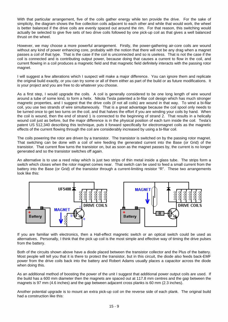
With that particular arrangement, five of the coils gather energy while ten provide the drive. For the sake of simplicity, the diagram shows the five collection coils adjacent to each other and while that would work, the wheel is better balanced if the drive coils are evenly spaced out around the rim. For that reason, this switching would actually be selected to give five sets of two drive coils followed by one pick-up coil as that gives a well balanced thrust on the wheel. However, we may choose a more powerful arrangement. Firstly, the power-gathering air-core coils are wound without any kind of power enhancing core, probably with the notion that there will not be any drag when a magnet passes a coil of that type. That is the case if the coil is unconnected and so is useless. That is not the case if the coil is connected and is contributing output power, because doing that causes a current to flow in the coil, and current flowing in a coil produces a magnetic field and that magnetic field definitely interacts with the passing rotor magnet. I will suggest a few alterations which I suspect will make a major difference. You can ignore them and replicate the original build exactly, or you can try some or all of them either as part of the build or as future modifications. It is your project and you are free to do whatever you choose. As a first step, I would upgrade the coils. A coil is generally considered to be one long length of wire wound around a tube of some kind, to form a helix. Nikola Tesla patented a bi-filar coil design which has much stronger magnetic properties, and I suggest that the drive coils (if not all coils) are wound in that way. To wind a bi-filar coil, you use two strands of wire simultaneously. That is a great advantage because the coil spool only needs to be turned once to get two turns on the coil, and that halves the effort if you are winding your coils by hand. When the coil is wound, then the end of strand 1 is connected to the beginning of strand 2. That results in a helically wound coil just as before, but the major difference is in the physical position of each turn inside the coil. Tesla’s patent US 512,340 describing this technique, puts it forward specifically for electromagnet coils as the magnetic effects of the current flowing through the coil are considerably increased by using a bi-filar coil. The coils powering the rotor are driven by a transistor. The transistor is switched on by the passing rotor magnet. That switching can be done with a coil of wire feeding the generated current into the Base (or Grid) of the transistor. That current flow turns the transistor on, but as soon as the magnet passes by, the current is no longer generated and so the transistor switches off again. An alternative is to use a reed relay which is just two strips of thin metal inside a glass tube. The strips form a switch which closes when the rotor magnet comes near. That switch can be used to feed a small current from the battery into the Base (or Grid) of the transistor through a current-limiting resistor “R”. These two arrangements look like this:
If you are familiar with electronics, then a Hall-effect magnetic switch or an optical switch could be used as alternatives. Personally, I think that the pick up coil is the most simple and effective way of timing the drive pulses from the battery. Both of the circuits shown above have a diode placed between the transistor collector and the Plus of the battery. Most people will tell you that it is there to protect the transistor, but in this circuit, the diode also feeds back-EMF power from the drive coils back into the battery and Robert Adams usually places a capacitor across the diode when doing this. As an additional method of boosting the power of the unit I suggest that additional power output coils are used. If the build has a 600 mm diameter then the magnets are spaced out at 117.8 mm centres and the gap between the magnets is 97 mm (4.6 inches) and the gap between adjacent cross planks is 60 mm (2.3 inches). Another potential upgrade is to mount an extra pick-up coil on the reverse side of each plank. The original build had a construction like this:
15 - 9

This arrangement has sixteen coils, each mounted one per plank. That is a very simple construction. However, it is possible to double the number of coils while still maintaining the great simplicity of the construction. The way to do that is to mount a second coil on the other side of the plank like this:
If the rotor is 600 mm in diameter, then the coils should not have a diameter of more than 38 mm. If 40 mm (1.5 inch) diameter coils are wanted, then make the rotor diameter 620 mm. Using these additional coils with this method does not have all the coils spaced out evenly around the rotor, but that does not matter in the least. Leaving the driving circuitry unchanged, there will still be 16 evenly spaced pulses for every 360-degree movement of the rotor. The additional coils are passive and pick up energy from the magnets as they pass by. However, with a coil on both sides of the plank, the new coils are only about 5 mm away from the next of the original coils and that is close enough to pick up the magnetic field from that coil when that drive coil is pulsed. One additional power upgrade would be to have two or three rotors on the one shaft. Doing that has considerable advantages, not the least of which is that each additional rotor can be added at a later date when it is convenient to do so. The arrangement looks like this:
15 - 10
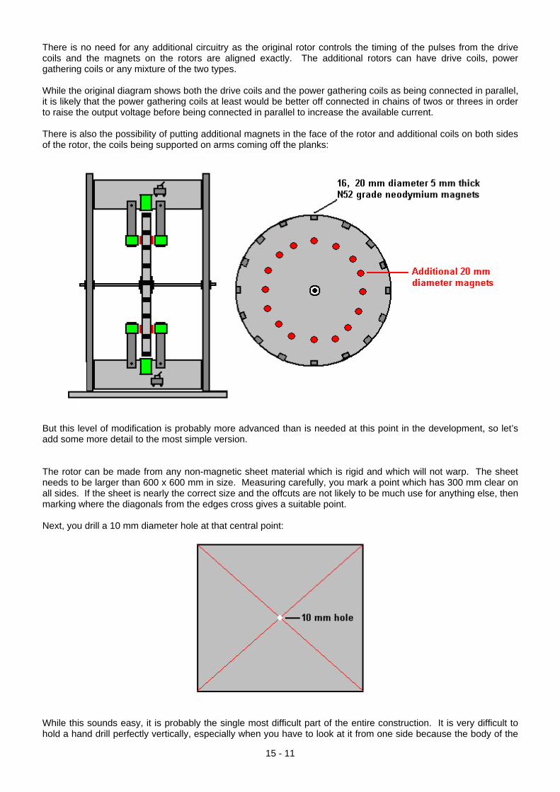
There is no need for any additional circuitry as the original rotor controls the timing of the pulses from the drive coils and the magnets on the rotors are aligned exactly. The additional rotors can have drive coils, power gathering coils or any mixture of the two types. While the original diagram shows both the drive coils and the power gathering coils as being connected in parallel, it is likely that the power gathering coils at least would be better off connected in chains of twos or threes in order to raise the output voltage before being connected in parallel to increase the available current. There is also the possibility of putting additional magnets in the face of the rotor and additional coils on both sides of the rotor, the coils being supported on arms coming off the planks:
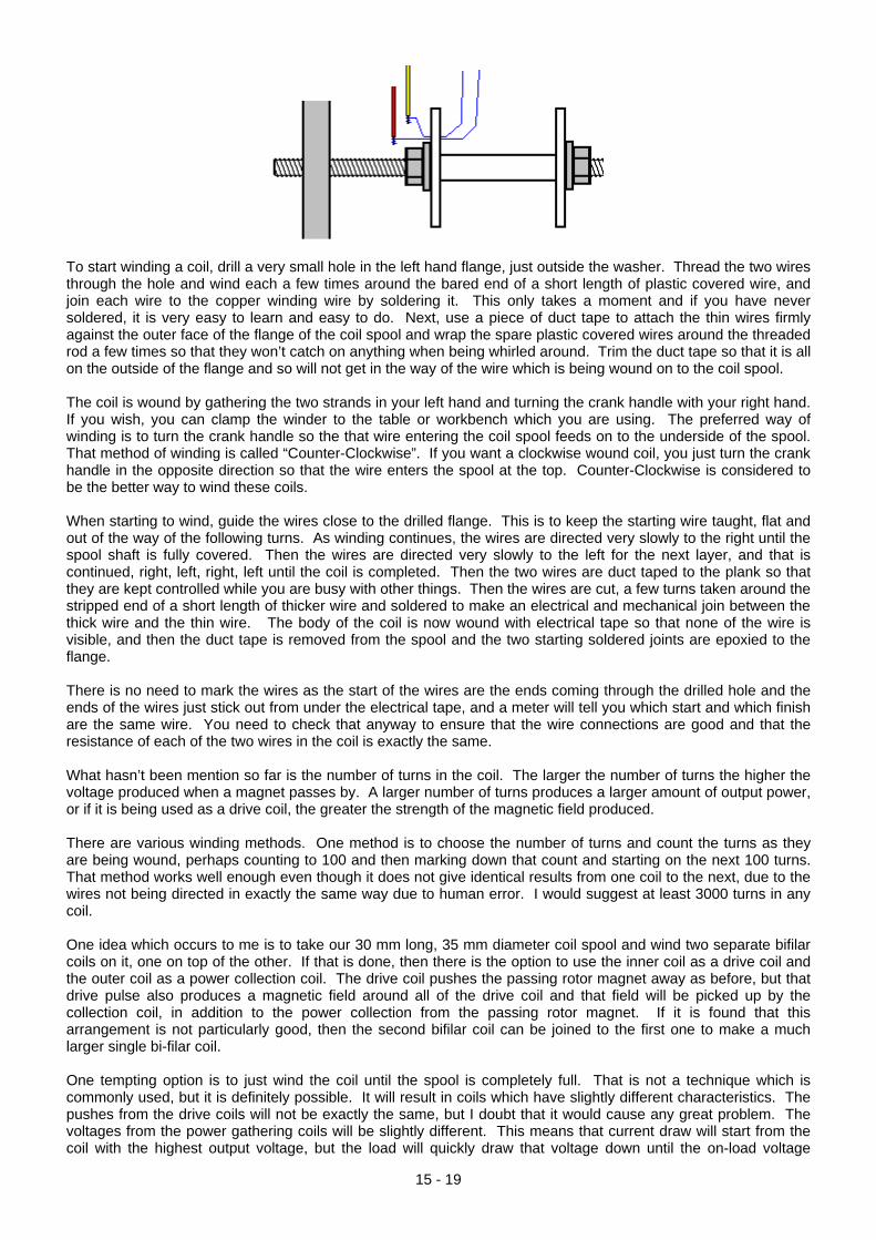
But this level of modification is probably more advanced than is needed at this point in the development, so let’s add some more detail to the most simple version. The rotor can be made from any non-magnetic sheet material which is rigid and which will not warp. The sheet needs to be larger than 600 x 600 mm in size. Measuring carefully, you mark a point which has 300 mm clear on all sides. If the sheet is nearly the correct size and the offcuts are not likely to be much use for anything else, then marking where the diagonals from the edges cross gives a suitable point. Next, you drill a 10 mm diameter hole at that central point:
While this sounds easy, it is probably the single most difficult part of the entire construction. It is very difficult to hold a hand drill perfectly vertically, especially when you have to look at it from one side because the body of the
15 - 11

drill blocks the view from vertically above. The board is too wide to use a normal drill press, and the notion of using something drilled in a drill press as a guide to the vertical while attempting to get the drill bit on the marked point which the guide now obscures is usually a recipe for disaster. To get over this problem, we will drill a sloppy hole by hand and use two nuts and two washers to force the rotor into an exactly vertical position as well as holding the rotor in place permanently. However, even though it is going to be a sloppy hole, do your best to drill it as square and upright as possible. Next, cover the hole over with tape pulled into a smooth surface and mark the exact centre of the hole on the tape:
Forget all previous markings. This central dot is what we work from now as everything is exactly related to that point, and only that point. Now, draw a line through the centre point, at any convenient angle. Then a second line through the point at exactly 90 degrees to the first line. If you wish, you can use a sheet of paper to get the 90 degrees:
The next step is to measure off exactly 300 mm from the central point along each of those four lines and connect those points “A”, “B”, “C” and “D” with straight lines:
15 - 12

Measure the length A to B, B to C, C to D and D to A. Those lengths should all be exactly the same. Now, mark the centre point of each of those four lines (points E, F, G and H):
and draw a straight line from the centre point through those four points and mark off exactly 300 mm from the centre point on each of those lines. This has now located 8 of the 16 magnet positions in exact relationship to the central hole:
The next step is to join each of those 8 points to the next one, mark the centre point on each and draw a 300 mm long line from the centre point through those points to show the positions of the final 8 magnets:
We now have the exact positions of all sixteen of the magnets, so remove the piece of tape and push your 10 mm diameter drill bit into the hole. Tie a loop in a piece of string and put the loop over the drill bit. Take a pencil and place the tip on one of your marked magnet positions, and then with the string wrapped round the pencil low down near the board, adjust the string so that it is tight and mark a 300 mm radius arc through all of the magnet positions. This is the edge of the rotor. Why didn’t we just do that instead of all the measuring? Because the string method is very easy to get badly wrong and we want the rotor to be as accurate as we can make it.
15 - 13

We now want to cut out the rotor (being careful not to erase the lines showing where the magnets are to be attached) and the inclination is to grab a power jig saw as that is the easiest way. However, I recommend that you don’t do that as power tools are very good at getting things wrong in less than one second. Cutting carefully and slowly using a coping saw should give you a perfect rotor whose edges can then be sanded. The advantage of a coping saw is that the blade angle can be set to allow very long cuts near the edge of a piece of material:
When the rotor has been cut out, mark 20 mm lengths at the magnet points and use the coping saw to remove a 5 mm deep slot the full width of the rotor material along each 20 mm length. This allows the magnets to be flush with the edge of the rotor. The rotor is the only precision item in the entire construction, so the most difficult part has now been completed. As it is more convenient to attach the coils to the cross planks before assembling the outer frame of the stator, we will cut the necessary pieces but not assemble them until after the coils have been completed. To cut out the side pieces, place the rotor on a thick sheet of material such as chipboard, Medium Density Fibreboard, plywood, block board or similar, in a position where there is 135 mm (5.5 inches) clear all around it. As the rotor is 600 mm in diameter, the side panel needs to be at least 830 mm square:
Mark the sheet through the rotor hole, remove the rotor and drill a 10 mm hole through the sheet. Place the drill bit in the hole in the sheet and slide the rotor down on to the drill bit. This matches the rotor exactly with the stator side panel. Carefully mark around the rotor with a pencil and remove the rotor and the drill bit.
15 - 14

Draw parallel lines 20 mm apart, running from the centre of the rotor outline, through each of the magnet slots. Allow for a 5 mm gap between the rotor and it’s matching plank and mark off a 90 mm length as shown above. This is to mark out the position where the plank will be attached to the side panel of the stator. As the plank is 38 mm wide, it will extend 9 mm outside the lines like this:
After the position of the plank end has been outlined, drill two holes to take the screws which will hold the two stator side panels together. When the first one has been completed, it will look like this:
That process is repeated for all sixteen planks, and that outlines the stator side panel well enough to allow it to be completed:
15 - 15

Leave 30 mm below the lowest plank position and 20 mm at each of the two side planks, and draw the horizontal and vertical lines shown in blue in the diagram above. Then, putting the drill bit back in the hole and using a piece of string and a pencil to improvise a very large compass, draw the red arc shown above. That completes the outline of the side panel of your stator, which can now be cut out. This cutting is not critical in any way, but it would be nice to have it looking neat. The completed side panel is now placed on a second panel and a pencil mark is made to show the position of the drilled hole. The second panel is drilled with a 10 mm diameter hole and the drill bit is used to make sure that the two holes align perfectly. A pencil line is now traced around the outside of the completed side and the second side panel is then cut out along that line. The 10 mm drill bit is now used to align the rotor and the second side panel, taking great care to align the rotor in exactly the same position as on the first side, and the end positions of the planks marked out and drilled ready to take the screws. Next, you take your two bearings and treat them to make them as free-spinning as possible, then, measure carefully out from the hole drilled in each of the two stator side panels and mark a circle of exactly the same diameter as the outside of the bearings. Use a power jig saw to cut out the circle staying just inside the line. This gives a rough opening which is just too small for the bearing to fit into. Enlarge the hole very gradually using a wood rasp or coarse sandpaper until a bearing can just be forced into the hole. Leave the bearing in place but don’t do anything further to attach it at this time – that will be done later when the axle is in place and the rotor has been proved to spin freely. The base panel is just a rectangle 850 x 500 mm in size, but we are not ready to assemble the unit just yet as we need to wind the coils and attach them to their support planks ahead of assembling the generator. We need to choose a wire diameter, coil dimensions, number of turns per coil and style of winding. Those items are the things which are changed when a builder says that he is “tuning” his generator to get maximum performance. It sounds much more impressive to say that you are “tuning” rather than to say that you are experimenting with different coils. So, let’s get started with our choices. The thicker the wire used, the greater the current which it can carry, but the fewer turns which will fit on to any particular coil spool. Also, the thicker the wire, the shorter the length which you get when buying it by weight. The thinnest wire, say, SWG 40 which is about one tenth of a millimetre in diameter, is liable to break when you wind it unless you are very careful and wind gently. The really thick wire is a bit stiff and can be a bit difficult to wind. However, we are not going to encounter those problems in this job as current handling capacity needs to be taken into account. The question we need to answer is “how much current can we draw from a coil when we swing a magnet past the coil?” and the answer is “probably not much”. So, we take a look at the table which shows the currents which the different wire sizes can carry comfortably:
15 - 16

AWG Dia mm Area sq. mm
SWG Dia mm Area sq. mm
Max Amps
Ohms / metre
Metres Per 500g
Max Hz
1 7.35 42.40 2 7.01 38.60 119 325 2 6.54 33.60 3 6.40 32.18 94 410 3 5.88 27.15 4 5.89 27.27 75 500
27 0.361 0.102 28 0.376 0.111 0.288 0.155 500 m 130 kHz 28 0.321 0.0804 30 0.315 0.0779 0.226 0.221 700 m 170 kHz 29 0.286 0.0646 32 0.274 0.0591 0.182 0.292 950 m 210 kHz 30 0.255 0.0503 33 0.254 0.0506 0.142 0.347 1125 m 270 kHz 31 0.226 0.0401 34 0.234 0.0428 0.113 0.402 1300 m 340 kHz 32 0.203 0.0324 36 0.193 0.0293 0.091 0.589 1900 m 430 kHz 33 0.180 0.0255 37 0.173 0.0234 0.072 0.767 2450 m 540 kHz 34 0.160 0.0201 38 0.152 0.0182 0.056 0.945 3000 m 690 kHz 35 0.142 0.0159 39 0.132 0.0137 0.044 1.212 3700 m 870 kHz
Looking at the smallest wire size shown, it can carry 44 milliamps, but it is so thin that it would be difficult to handle. I have wound successfully with SWG 40 but it is not the most convenient. I would suggest SWG 36 which is AWG 32 and has a diameter of nearly one fifth of a millimetre. It can carry 91 milliamps continuously and a good deal more when it is the pulsed current produced by a magnet passing by. The table shows that if we buy two 500 gram reels of SWG 36, then we receive a length of three thousand eight hundred metres of wire for winding our coils. Every extra coil that we wind, increases the power of the generator, so we will be winding a lot of coils. It is not at all difficult to wind these coils, but it will take a few days. For people living in the UK, the best supplier is the Scientific Wire Company who manufactures the wire. In November 2015 they sell two 500 gram reels of SWG 36 wire (their Ref: SX0190-2x500 ) for just £18 including tax at http://wires.co.uk/acatalog/SX_0190_0280.html and that is ‘solderable’ enamel which just burns away when you solder to it, which is enormously helpful, especially with very thin wire. Alternatively, if you choose two 500 gram reels of SWG 37 wire with 72 milliamp current carrying capacity (their Ref: SX0170-2x500) at http://wires.co.uk/acatalog/SX_0140_0180.html then the cost is £19.72 but the wire length has increased to four thousand nine hundred metres, which is an extra 1,100 metres of thinner wire. Please remember that the wire current carrying capacity is not all that important as many coils are involved. For example, if each coil is contributing 30 milliamps (which is well inside the ability of the wire to manage) and there are ten coils connected in parallel, then the combined current is 300 milliamps which is well outside the capacity of any single wire to carry. Just remember that if they are connected in parallel and feeding the power away, then you need a much larger diameter wire to carry that combined current from the set of coils to its destination. When winding a coil, you need to choose the starting diameter of the coil. The magnetism produced by a coil increases with the number of turns, more turns produces more magnetism. The magnetism also increases with the area inside each turn of the coil, the bigger the area the bigger the magnetism. The snag is that the bigger the enclosed area, the greater the wire length needed to complete each turn of the coil wire. So, the question is should we use a small diameter coil shaft or a thick coil shaft? In this case we want a large number of turns on a coil of not more than 38 mm diameter, so we will choose a narrow tube for our coils. We can make up coil spools quite easily if we use a power drill and a hole saw set like this:
15 - 17

These saw sets normally have a saw which has an inner diameter of 35 mm. That doesn’t sound very large but the wire being used does not build up much depth of turns when being wound, even with a large number of turns in the coil. A small sheet of 3 mm thick Medium Density Fibreboard (“MDF”) can easily be drilled using the hole saw, and each drilling produces one perfectly round disc with an exactly centred hole in the middle. Two of those can be glued (at exact right angles to the central shaft) on to a tube to form a spool of the size wanted. If it is available, plastic sheet could be used instead of the MDF. Plastic tube of 8 mm diameter and an inner diameter of 6 mm is often available on eBay, but failing that, it is actually quite easy to drill a 6 mm hole through a short length, say, a 30 mm length of 8 mm diameter dowel rod. The piece of dowel is held in a vise and because it is easy to see, drilling a reasonable hole down the length of dowel is not actually that difficult. The spool can be clamped on to a standard 6 mm diameter threaded rod using two washers and two nuts or wing nuts:
Then the threaded rod can be clamped at one end with a simple crank handle formed out of a small piece of timber, a clamping screw to grip the rod and a 20 mm length of drilled dowel on a screw to form the rotating winding handle:
A simple drilled hole in the vertical sides works perfectly well as a bearing, but keep the length “A” short as that needs less wrist movement and with it short, it is quite easy to turn the handle four times per second. A plank around 600 mm long makes a good base for the winder:
The winding handle part is at the near end and the two 500 gram spools of wire are placed one above the other at the far end. The longer the plank, the easier it is to draw wire from the large supplying spools as the angle between those spools and the spool being wound is smaller. The supplying spools are each just mounted on a dowel pushed through holes in the side pieces. Be sure to make those dowels horizontal so that the spools don’t keep moving to one side or the other.
15 - 18
To start winding a coil, drill a very small hole in the left hand flange, just outside the washer. Thread the two wires through the hole and wind each a few times around the bared end of a short length of plastic covered wire, and join each wire to the copper winding wire by soldering it. This only takes a moment and if you have never soldered, it is very easy to learn and easy to do. Next, use a piece of duct tape to attach the thin wires firmly against the outer face of the flange of the coil spool and wrap the spare plastic covered wires around the threaded rod a few times so that they won’t catch on anything when being whirled around. Trim the duct tape so that it is all on the outside of the flange and so will not get in the way of the wire which is being wound on to the coil spool. The coil is wound by gathering the two strands in your left hand and turning the crank handle with your right hand. If you wish, you can clamp the winder to the table or workbench which you are using. The preferred way of winding is to turn the crank handle so the that wire entering the coil spool feeds on to the underside of the spool. That method of winding is called “Counter-Clockwise”. If you want a clockwise wound coil, you just turn the crank handle in the opposite direction so that the wire enters the spool at the top. Counter-Clockwise is considered to be the better way to wind these coils. When starting to wind, guide the wires close to the drilled flange. This is to keep the starting wire taught, flat and out of the way of the following turns. As winding continues, the wires are directed very slowly to the right until the spool shaft is fully covered. Then the wires are directed very slowly to the left for the next layer, and that is continued, right, left, right, left until the coil is completed. Then the two wires are duct taped to the plank so that they are kept controlled while you are busy with other things. Then the wires are cut, a few turns taken around the stripped end of a short length of thicker wire and soldered to make an electrical and mechanical join between the thick wire and the thin wire. The body of the coil is now wound with electrical tape so that none of the wire is visible, and then the duct tape is removed from the spool and the two starting soldered joints are epoxied to the flange. There is no need to mark the wires as the start of the wires are the ends coming through the drilled hole and the ends of the wires just stick out from under the electrical tape, and a meter will tell you which start and which finish are the same wire. You need to check that anyway to ensure that the wire connections are good and that the resistance of each of the two wires in the coil is exactly the same. What hasn’t been mention so far is the number of turns in the coil. The larger the number of turns the higher the voltage produced when a magnet passes by. A larger number of turns produces a larger amount of output power, or if it is being used as a drive coil, the greater the strength of the magnetic field produced. There are various winding methods. One method is to choose the number of turns and count the turns as they are being wound, perhaps counting to 100 and then marking down that count and starting on the next 100 turns. That method works well enough even though it does not give identical results from one coil to the next, due to the wires not being directed in exactly the same way due to human error. I would suggest at least 3000 turns in any coil. One idea which occurs to me is to take our 30 mm long, 35 mm diameter coil spool and wind two separate bifilar coils on it, one on top of the other. If that is done, then there is the option to use the inner coil as a drive coil and the outer coil as a power collection coil. The drive coil pushes the passing rotor magnet away as before, but that drive pulse also produces a magnetic field around all of the drive coil and that field will be picked up by the collection coil, in addition to the power collection from the passing rotor magnet. If it is found that this arrangement is not particularly good, then the second bifilar coil can be joined to the first one to make a much larger single bi-filar coil. One tempting option is to just wind the coil until the spool is completely full. That is not a technique which is commonly used, but it is definitely possible. It will result in coils which have slightly different characteristics. The pushes from the drive coils will not be exactly the same, but I doubt that it would cause any great problem. The voltages from the power gathering coils will be slightly different. This means that current draw will start from the coil with the highest output voltage, but the load will quickly draw that voltage down until the on-load voltage
15 - 19

reaches that of the second highest voltage coil, and then both will be drawn down to the third highest voltage, and so on. So, the choice of winding style is yours. No matter which method you use, you end up with a set of 16 or 31 coils ready for installation. Irrespective of the number of coils being installed, mark the centre point on both sides of every plank. If your coil winding has left an unused section of flange on the coil spool, cut it off on one side so that the turns of wire can be attached directly to its plank. Position the coil on the middle mark and attach it to the plank in a non-permanent way, such as using a metal strap or wooden strap screwed to the plank, straddling the turns of the coil. The attachment has to allow you to adjust the coil position towards, or away from, the rotor.
Join the end of the first strand of the coil winding to the start of the second strand. If you want to use switches (and that is really unnecessary in our construction) then solder the remaining wires to the central contact of each side of a miniature two pole changeover switch:
Glue a small spacer 15 mm thick, to the side of the switch and then glue the spacer to the plank. That lifts the switch up high enough to make soldering other wires to the switch much easier. The original build used single pole switches, assuming that there would be a common negative line to all of the coils. In this implementation, we would use double pole switches so that the coil can be switched into more advanced circuit configurations as we want to experiment with power collection coils connected in separate groups. We really do not need switches. If a coil is being used on both sides of each plank, then attach the second coil to the centre of the plank’s other face. The magnets need to be attached to the rotor. It is said that the North-seeking pole is four times stronger than the South-seeking pole of any permanent magnet when used in an application of this type. If you don’t know which face of the magnets is North, then take a stack of two or four magnets and suspend them on a thread so that they are roughly horizontal. After a few minutes, the magnets will align along a definite line and the magnet face which is facing towards the North is the North-seekng pole face. If you don’t know which direction is North from where you are, consult a map, of if the Sun rises in the morning and you face the rising Sun, then North is on your left. Once you have established which magnet pole is North, then the attraction or repulsion of the other magnets shows which is their North pole face. Epoxy the magnets in place on the rotor edge with the North pole face facing outwards. Some people are inclined to put duct tape around the rotor outside the magnets to make sure that the magnets don’t fly off the rotor when it is spinning. It is my experience that rotors of this type spin slowly at one revolution per second or slower, and that speed will never, ever, dislodge a rotor magnet, and if it did, there would be no significant energy in the loose magnet anyway, but if you feel inclined to do so, apply a 20 mm wide strip of duct tape on top of the magnets. We are now ready to assemble the main components of the generator. People will have different ideas about how this should be done and there are various opinions about the best way. The cross planks will be attached to the sides of the stator using two screws on each side of every plank. That allows the unit to be taken apart later on if that should be necessary. The screws of the original were placed like this:
15 - 20

Personally, I would like the screws to be offset so that neither is on the centre line of the plank as that is the weakest arrangement, and so I suggest that the two screws are positioned one third of the way in from the plank edge as that gives a stronger connection with the screws 13 mm apart and not stressing the timber alomg one plane. When the two stator sides are connected together by the planks, it is quite difficult to get at the planks half way up the stator. To overcome that difficulty, we can attach the planks to one side and make all wiring connections to the coils and switches. Those wires can then be run along each plank and through the stator side so that they will be easily accessible when the unit is fully assembled. It is very much easier to have the wiring on the outside, both for understanding it initially and for making changes afterwards if experiments are tried in the search for optimising the performance of the generator. You would think that connecting a cross plank to the stator side would be ever so easy. It actually isn’t all that easy and getting the screws set correctly and the plank exactly in place is not a trivial task as the screws tend to push the plank out of position. One way to overcome this and get an accurate result is to clamp the end of the plank firmly in place before driving the screws into the plank. That can be done using two pieces of scrap timber:
The piece on the left is cut so that a plank fits tightly in the cut out. The opening is positioned exactly where the plank should go and the piece clamped securely to the stator. The second piece is then clamped to the stator so as to complete the enclosure. This allows the plank to be pressed securely into place against the stator and the screws driven in while pressure is applied to keep the plank pressed securely against the stator with no chance of movement or any gap allowing screws to be driven in at an angle and causing a mismatch and the subsequent weakness of an inferior join. Clamping becomes impossible for the lower part of the side panel because of the increasing distance of the plank from the edge. In that area, the guide can be screwed to the inside of the side panel using short screws which do not go all the way through the side panel. The guides have to be kept fairly narrow as there is not much clearance between adjacent planks. The four switching wires from the switches, or the two coil wires if switches are not being used, are run through the side of the stator and connected to an ordinary screw terminal strip:
15 - 21

This arrangement allows complete flexibility for any arrangement of interconnections, but there is a more simple arrangement which needs no switches and that is to run the two coil wires directly out to a screw terminal strip and then make all of the subsequent interconnections with a screwdriver:
Although some coils can be connected with just two screw terminals, I suggest that four are allocated to every coil. That allows circuitry to be constructed using the terminal strips themselves. When all of the cross planks have been attached to one of the stator side panels, attach that side to the base plate. That can be done by screwing a wooden batten to the base plate and then screwing the side panel to the batten, ensuring that the side panel is exactly vertical.
15 - 22

Then, put the rotor in position, through the bearing in the stator side panel, slip the other end of the axle through the bearing in the second side panel and attach the second side panel to the base plate:
This diagram does not show the planks attached to one side as including them would not be helpful as they would conceal the main details. Ensure that the base is horizontal and both sides are exactly vertical and then attach the planks to the second side panel using the clamping pieces:
Once most of the planks have been attached, the base (with the battens attached) can be removed temporarily in order to make the remaining plank attachments easier to reach. At this point, most of the construction is completed with the base, two side panels, rotor with magnets, sixteen planks and one full set of coils with their connections carried through one stator side to screw connector terminals. So now we are ready to wire up the connections and run the generator. We use a transistor to power the generator. There are lots of different transistors and so we need to choose one. A very popular and powerful one is the 2N3055 which in its more convenient more recent packaging is called the TIP3055 transistor looks like this:
15 - 23

This transistor is popular and is available in many different countries. Transistors are basically, very simple devices to understand. They are made of two pieces of N-type silicon separated by a very thin layer of P-type silicon. The “N” and the “P” just stand for “Negative” and “Positive”. It works like this: If you have a block of N-type silicon (which we call a ‘diode’) and connect a battery across it, current will flow provided that the battery is connected the right way round:
A transistor is two of those N-type silicon blocks separated by a very thin layer of P-type silicon to control the operation. The P-type forms a barrier when the N-type silicon would normally conduct a current:
However, if a small current flows into the Base and out through the Emitter, then the barrier effect is reduced by a large amount and a current starts flowing from the Collector to the Emitter:
The ratio of the base current to the Collector current which it triggers is called the DC power gain. For example, if one milliamp of current flows into the base and causes a current flow through the transistor of 30 milliamps, then the gain is said to be 30, and that is about the gain which we can expect from a TIP3055 transistor. That is not a very high gain and it would be nice if it were much higher. We can arrange that increase in gain by using one other transistor – a low power transistor which has a high gain of about 200, say, a BC109C or a 2N2222A transistor. If we use one of those to amplify the current going into the base of the TIP3055, then the overall gain becomes 200 x 30 which is six thousand. A gain of 6000 should work very nicely for our generator. The way that we use the transistors is we have one coil act as a synchronisation or timing sensor. It detects a rotor magnet passing by because the magnet generates a voltage in the coil and we use that voltage to switch on our pair of transistors:
This works as follows. When the rotor magnet passes the timing coil, it generates a voltage in that coil. Each transistor needs about 0.7 volts to switch on, so if the voltage generated in the timing coil exceeds 1.4 volts (which
15 - 24

is pretty certain for a coil with many turns in it) then that voltage will cause a current to flow through the Base of the small transistor. That turns the small transistor On, feeding a generous current into the base of the big transistor through the 47 ohm resistor which limits the size of that current, turning the TIP3055 transistor On and causing a large current to flow through it. If we connect the generator’s drive coils between the collector of the large transistor and the battery Plus terminal, then that big current will flow through those coils, powering the rotor on its way. By adjusting the position of the Timing Coil, we can control exactly when the drive coils get powered up, and so we can adjust the position to get the very best performance from the generator. The circuit diagram for this is:
Physically, that is:
Here, the red positive connection to the battery goes to the Collector of the 2N2222A transistor and to one side of all of the drive coils. The green wire connects to the other side of all of the drive coil connections and on to the Collector of the TIP3055 transistor. The Minus of the battery goes to the Emitter of the TIP3055 and to one side of the single timing coil and the other side of the timing coil goes to the Base of the 2N2222A transistor. If you don’t want to solder connections to transistors, then you can bend the centre leg upwards and use individual, trimmed down screw terminals, one on each leg:
I suggest that initially, you ignore the power take off circuitry and concentrate on getting the rotor spinning satisfactorily. However, just before starting on that, consider the first circuit diagram shown and consider the difference:
15 - 25

You will notice that there is a diode between connected across the drive coils. The direction of the diode will not allow current to flow from the battery through it (it would have to be connected the other way round if we wanted that to happen – which we don’t). A feature of coils, especially coils with lots of turns, is that if they have a current flowing through them, they really, really don’t like that current flow to be stopped. If it is, then they generate a large voltage spike in the reverse direction. If the battery is a 12-volt battery and the transistor is switched hard On, that connects the full battery voltage across the coils and so causes strong current flow through the coils. When the transistor switches Off it stops the current flow through the coils, which promptly generates a major reverse voltage in the coils. Because one side of the coils is connected to the battery Plus, that voltage drags the collector of the transistor to a much higher voltage than the voltage of the battery. This worries circuit designers as the transistor might not be able to survive such a high voltage, and so they connect a diode from the battery Plus to the transistor Collector. The thinking behind this is that once the transistor Collector is dragged to 0.7 volts or more, above the battery voltage, then the diode will start to conduct and that will collapse the voltage spike of the coils and prevent the voltage getting much above the battery voltage. That does happen, and yes, it does protect the transistor from being damaged by excessive voltage. But, consider the current flow through the diode. It is connected to the battery Plus, and so any current flows back into the battery as it has no alternative flow path. That recovers some of the current used to drive the generator, so the diode is much more useful than just protecting the transistor (especially since we could use a transistor able to withstand the high voltage generated). Please note that the diode is a UF5408. The “UF” stands for Ultra Fast, meaning that the diode is able to switch On and Off very quickly indeed. That is important when we are dealing with very fast, very sharp voltage spikes like those generated by our coils, so please don’t assume that any old diode will do the job for us, as we need a fast one. Just before we leave the drive coils to move on to the power gathering coils, let me confirm how they are connected. Initially, we need the biggest possible push from the coils and so they are connected ‘in parallel’. That is, like this:
The start of each drive coil is connected to the start of every other drive coil (the blue line) and the end of each drive coil is connected to the end of every other drive coil (the red line). The TIP3055 power transistor applies the full battery voltage to all drive coils simultaneously. Initially, I would suggest that you try ten drive coils as that was what suited the original build, although it is highly unlikely that those coils are the same as your coils. To get the rotor started requires giving it a push in the right direction. That will start the pulsing drive pushing the rotor around and it will accelerate to its working speed all on its own. Some people may feel that the rotor could rotate in either direction. That would be the case if, and only if, the timing coil is positioned centrally without any movement when the wheel performance is optimised after the power collection coils have been wired up and are contributing output power. So, choose a direction of rotation and stay with it at all times.
15 - 26

When a magnet passes close to a coil of wire, the result is a voltage between the ends of the coil. That voltage varies with time and is generally a sine wave shape which varies slowly compared to the voltage spikes of the rotor-powering coils when they are switched Off, and so, any diode can be used to convert that voltage to Direct Current. Ideally, you have 3000-turn coils mounted on the second side of the fifteen active planks (the sixteenth plank being exclusively for timing and adjusting for the best possible performance, certainly on the first rotor, any additional rotors don’t need a timing coil as we already have that). For the moment, leave the remaining five rotor-powering coils unused as we can decide later if they are to be powering coils or power-gathering coils. We won’t know that for sure until we start drawing current from the generator, because that current flowing in the output coils causes a magnetic field which alters conditions for the rotor. So, we need to see how it goes when we are drawing current from the generator. I suggest that every power output coil is treated exactly the same as all of the other power gathering coils. First, we use four diodes to convert all of the coil power from AC to DC. This is done with a standard bridge configuration like this:
This arrangement may look a little strange. The four diodes are not a bridge although electronically they do form one. These can be four separate, discrete diodes such as the 1N4148 or the 1N4007 both of which are incredibly cheap as they are so popular. Alternatively, a 1.5 amp 100V single-package diode bridge can be used nearly as cheaply. The capacitor shown is very helpful for testing as well as for producing a good output. It can be quite small in value, perhaps 100 microfarads or 1000 microfarads if you prefer. It is easier to check the output voltage on each power gathering coil when there is a capacitor in place, and you get an increased capacity smoothing capacitor with every output coil added. A possible physical layout is:
The original build was to show conclusively that the generated output power was greater than the input power. That was the reason for all of the meters used on the original. As the input power was DC and the output power was DC, measuring the input voltage and current gave the input power, while measuring the output voltage and current gave the output power and the demonstrations showed that the output power was more than three times larger than the input power. That being the case, we should be able to get the generator running and then switch from battery input to feeding the input from a capacitor powered by several of the output coils. This type of rotor drive is really good for doing this, because the drive voltage is not particularly important. I can see no reason why this generator cannot be self-powered and still supply power for other uses. With three rotors, many magnets and many coils, it should be possible to extract significant power from this generator. Even if that were not the case, there are various devices in chapter 14 (“renewable energy systems”) which need very little power to be useful – lighting, cooling, etc. One really big advantage of this design is that it is easy to understand, easy to expand, and does not need any specialist skills. Also, while a number of hand tools have been used in the construction, if you do not already own those tools you don’t necessarily have to buy them. It is likely that a friend has them and can lend them to you or alternatively, a local hire shop can rent you those tools for a day or even half a day at a very low charge.
15 - 27

If you prefer not to make coil spools for yourself, then it is possible to buy the wire on a large number of 50-gram reels. The reels supplied by the Scientific Wire Company are good quality plastic, 40 mm diameter, 30 mm tall, with 2 mm thick flanges, which leaves a shaft length of 26 mm. You can wind the wire off one spool on to any suitable temporary holder, giving you one empty spool. That spool can then be wound from two of the full spools and that gives you two empty spools. Every spool wound, gives you an extra empty spool. As the 40 mm diameter flange is wider than we need, after the coil has been wound, the excess flange width can be cut off with your coping saw:
The hole through the shaft of the spool is 10 mm in diameter but that is no problem as the 6 mm diameter threaded rod of your winder can easily be expanded to 10 mm by wrapping a length of masking tape, duct tape, electrical insulating tape or any other similar tape, around the shaft to align the spool which is then clamped in place by the nuts and washers. If your particular build of this generator produces a voltage which is lower than you want, then instead of connecting the output coils in parallel you can start by connecting them in pairs before making the parallel connections:
The second arrangement is called connected “in series parallel” and naturally, as they are only half the number of pairs of coils as there are single coils, the overall current is only half of what it is when the coils are connected in parallel. However, the power is exactly the same no matter how the coils are wired together. To tune the generator for best output, you can connect a voltmeter (usually a multimeter set to it’s 20-volt DC range) across any output coil’s capacitor and move the timing coil slowly to find the position of the timing coil which gives the greatest output. That is why it is probably best to have the timing coil on the top plank where it is easiest to get at. There are a couple of additional things which you may care to try out to see if they work well. They both are a different style of drive coil. The first comes from what is known as the Thomas Motor as shown in the video https://www.youtube.com/watch?v=9s7sM3csFHM&feature=youtu.be. This drive is a strong but small permanent magnet which is placed inside a wire wrapped ferrite toroid. When the toroid winding is energised by passing a current through it, the resulting magnetic field circling around the toroid blocks off the field of the permanent magnet, acting as a very effective magnetic shield:
15 - 28

The toroid used is probably the 22.5 x 13.5 x 10 mm toroid from China, currently selling at £5.01 for a pack of ten toroids delivered from China:
The above video has some errors in it so please use common sense and use the technique rather than paying undue attention to what is said. The toroid is wound with one continuous helical counter-clockwise coil going all the way around the core. The one shown is wound with approximately 10 metres of 38 gauge enamelled copper wire which has a diameter of 0.15 mm. The permanent magnet used is 6 mm diameter and 3 mm thick. If the rotor magnets have the North pole facing the coils, then the North pole of the magnet inside the toroid, faces the rotor and the coil is energised until the rotor magnet has just passed and then the current is cut off to allow the toroid magnet to push the rotor on its way through repulsion. The second method is using the Steorn ‘Orbo’ style coils (with no toroid magnets). These toroids are also wound in the same way using ferrite toroids as shown here: https://www.youtube.com/watch?v=aCpniBm9i_M and described in chapter 1. With no current flowing through the winding, the rotor magnets are attracted towards the ferrite toroids. When the rotor magnets align with the toroids, the current is switched on, blocking the ferrite toroid from the rotor magnets and letting the momentum of the rotor carry the rotor magnets half way towards the next toroid, where the current is cut off and the attraction starts all over again. For best effect, the hole in the centre of the toroids faces towards the rotor and not as shown in the above video. This technique of letting the rotor magnets provide the power which spins the rotor is the method used by Robert Adams in his COP=8 motor generators shown in chapter 2.
---------------- If you are confused by the many possible options for making a generator of this general type, then I would suggest that you choose to have just one rotor with sixteen magnets on it, and 31 coils each with 3000 bi-filar wound turns (that is, one coil on both sides of each plank except for the timing coil plank). If you choose to construct this generator, then good luck with your project. Remember that increased power comes with more coils, more rotors, more coil turns. I would expect you to have a lot of fun adjusting and optimising this generator. Patrick Kelly www.free-energy-info.com www.free-energy-info.tuks.nl www.free-energy-devices.com
15 - 29