chapter 16: dc circuits
TRANSCRIPT

Van Heuvelen/Etkina Process Physics 1/e, Chapter 16 16-1
Chapter 16: DC Circuits x Why might all the electrical devices in your house suddenly turn off if you simultaneously
turn too many on? x How can you use an electric circuit to model the circulatory system? x Why is it dangerous to use a hair drier while taking a bath?
Make sure you know how to: 1. Apply the concept of the electric field to understand electric interactions. 2. Define the V-field (electric potential) and electric potential difference 'V . 3. Explain the differences in internal structure between conducting materials and non-conducting
materials.
On a cold Sunday morning you turn on an extra heater in the kitchen and put a waffle in the toaster oven. You are heading for a Frisbee game on the snow and remember your uniform is dirty—you start the washing machine. Then you see that the dishwasher is full of dirty dishes, so you turn on the dishwasher. Now you are ready to make coffee. You turn on the coffee bean grinder and all of a sudden the lights in the kitchen go off. The dishwasher stops bubbling and the red heating element in the toaster oven dims. All the lights go out. What happened? Why did turning on a coffee grinder make the lights and all of the appliances go off? When you turn on too many appliances, a device called a circuit breaker disconnects the house from the external supply of electric energy to save the house from a potential fire. We will learn in this chapter how the circuit breaker “knows” when to turn off the energy supply to your house.
In Chapters 14 and 15 we learned about electric force and energy and how to explain
them using the idea of electric fields. We were mostly interested in phenomena involving macroscopic objects with electric charge, such as your body after you have rubbed your shoes on carpet. However, much of our modern technology involves processes when the charged objects are microscopic and moving. This is what is happening internally inside cell phones, computers, light bulbs, and nearly every other electrical device. It is also what happens inside the human body’s nervous system. In this chapter we will learn how to explain some of what is happening in these situations.
16.1 Electric charge flow In the previous chapter we studied processes that occurred when one charged conducting
object was connected with a wire to another non-charged conductor. We found that the excess

Van Heuvelen/Etkina Process Physics 1/e, Chapter 16 16-2
electrical charge on the charged object redistributed itself until the electric potential or V -field on the surfaces of both conductors became equal. This phenomenon relates closely to the subject of this chapter—electric circuits. Let’s repeat this type of experiment using two electroscopes and a light bulb. Causing a neon bulb to flash
Place the two identical electroscopes near each other and change electroscope 1 by rubbing it with a plastic rod that was rubbed vigorously with felt (Fig.16.1a). The leaves of electroscope 1 separate because of excess negative charge on them. If we touch a wire from charged electroscope 1 to uncharged electroscope 2, the leaves of 1 instantly separate less and the leaves of 2 instantly separate more (but not as much as the original separation of the leaves of 1)—see Fig. 16.1b. Evidently, the excess negative charge originally on 1 redistributed itself on the two electroscopes so they reached the same electric potential V , at which point charge transfer stopped.
Figure 16.1(a)(b) Transferring charge between electroscopes
Now repeat the experiment only this time, connect the charged electroscope 1 to the
uncharged electroscope 2 by the leads of a neon light bulb (Fig. 16.1c). The leaves behave the same way as in the previous experiment. As the leaves of electroscope 1 move closer and of electroscope 2 move apart, the neon bulb produces a quick flash of light. An explanation for this brief flash is that light is produced in a neon bulb when electric charge moves through the neon bulb due to a potential difference across its leads.
Figure 16.1(c)

Van Heuvelen/Etkina Process Physics 1/e, Chapter 16 16-3
Water analogy
To understand the process, think of the following analogy. You have two containers with water – A and B. A is almost full, and B is almost empty. You connect a hose between the two containers (Fig. 16.2a). Water starts flowing from A to B until the levels are the same (Fig. 16.2b), at which point the water flow stops. Here the amount of water in the container A is similar to the excess charge on the electroscope 1, and the difference in water pressure in the hose is similar to the potential difference between the electroscopes. The water flows till the pressure on both sides of the hose is the same; the electric charge flows till the potentials are the same.
Figure 16.2(a)(b) Water flow analogy for electric charge flow
It is the pressure difference and not the amount of water that makes the water flow.
Imagine a large container A full of water with the water level the same as in small container B – the water will not flow (Fig. 16.3a). Similarly, it is not the total charge difference between the electroscopes or metal spheres on their tops but the potential difference that makes the charge flow. Imagine big charged sphere A and small charged sphere B. Suppose the charge on A is large and on B is small; but, if the V fields on the surfaces of these two spheres (electric
potentials) are the same (V kqR
), there will be no charge flow through the wire conducting
them (Fig. 16.3b).
Figure 16.3(a)(b) Get flow only in PA > PB of VA > VB
Now, think of how you can make the process go on for a long time. You can manually
take water from container B and move it back to A, thus causing the levels in the containers to differ; the water starts flowing again from A to B. Or you can connect the containers with another hose with a pump in the middle that moves water from B back to A (Fig. 16.4). Both you moving the water manually from B back to A or pumping water from B back to A maintains a pressure

Van Heuvelen/Etkina Process Physics 1/e, Chapter 16 16-4
difference between A and B and causes continuous flow through the hose from A to B. How do we create a continuous electric charge flow in an electrical system?
Figure 16.4 Pump keeps pressure higher in A
Causing the neon bulb to have a steady glow
As we saw from the analogy, for steady water flow through the hose we need to maintain a steady difference in water pressure at the ends of the hose. For steady flow of electric charge, we need a device that can maintain steady potential difference between the ends of the neon bulb.
Let’s attach wires from the positive and negative terminals of a battery to the leads of the neon bulb (Fig. 16.5a). The bulb does in fact have a steady glow. Thus, it appears that the battery produces a steady potential difference across its terminals, which in turn causes a steady flow of electric charge passing through the neon bulb. The battery is the “electric pump”! Notice that the leads of the bulb are connected to the two terminals of the battery; we can draw a complete loop going through the battery and the bulb with the leads (Fig. 16.5b). This loop is called a complete circuit.
Figure 16.5 (a)(b) A neon bulb and battery electric circuit
Electric current Let us go back to the analogy with water and container A and B with different water
levels. If there is no hose connecting the two, the water will not flow even if the levels are different. With the hose, the water will flow slowly through a narrow hose, and faster through the wide hose. Knowing the speed with which the water is going through the cross sectional area of the hose is important if we want to use this flowing water to turn a paddle wheel or do something

Van Heuvelen/Etkina Process Physics 1/e, Chapter 16 16-5
else. The mass of water passing though a cross sectional area of a hose per unit time is called water current. The physical quantity water current characterizes the coordinated motion of water through the hose.
Similarly, the electrically charged particles move through the wire between two locations that are at different electric potentials. This potential difference is produced briefly by the presence of two electroscopes whose spheres are at different potentials or continuously by a battery. When the two locations are connected with a conducting wire, the movable charged particles in the wire move in a continuous coordinated way similar to the water moving though the hoses in a coordinated way. The physical quantity electric current I characterizes this coordinated movement of charged particles.
In most electric circuits, the charged particles that move in a coordinated way are free electrons in the wires and circuit elements (Fig. 16.6a). They flow toward the direction of higher
-fieldV (towards the positive terminal of a battery.) However, traditionally, the direction of electric current I is defined to be in the opposite direction to the motion of the electrons. Imagine that positively charged particles are flowing from the terminal at a higher electric potential (labeled “+” on the battery) through the wires and electrical devices, to the terminal at lower electric potential (labeled “–“), then through the battery to the positive terminal, and then the cycle starts over (Fig. 16.6b).
Figure 16.6(a)(b) Current in opposite direction to electron motion
This definition of the direction of the electric current is a historical quirk. When scientists
first studied electric processes, they did not know about electrons and instead thought that an invisible positively charged electric fluid flowed around the circuit (recall this from Chapter 14). For most situations involving electric circuits, it does not matter if we model the process in terms of electrons flowing one way or imaginary positive charges flowing the other way; so this historical convention is not a problem.
Electric current The electric current I in a wire equals the magnitude of the electric charge Q that passes through a cross section of the wire divided by the time interval 't needed for that amount of charge to pass:
Q
It
'
(16.1)
Van Heuvelen/Etkina Process Physics 1/e, Chapter 16 16-6
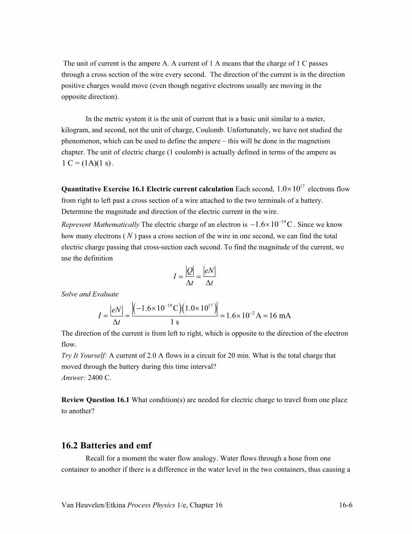
The unit of current is the ampere A. A current of 1 A means that the charge of 1 C passes through a cross section of the wire every second. The direction of the current is in the direction positive charges would move (even though negative electrons usually are moving in the opposite direction).
In the metric system it is the unit of current that is a basic unit similar to a meter, kilogram, and second, not the unit of charge, Coulomb. Unfortunately, we have not studied the phenomenon, which can be used to define the ampere – this will be done in the magnetism chapter. The unit of electric charge (1 coulomb) is actually defined in terms of the ampere as 1 C = (1A)(1 s) .
Quantitative Exercise 16.1 Electric current calculation Each second, 171.0 10u electrons flow from right to left past a cross section of a wire attached to the two terminals of a battery. Determine the magnitude and direction of the electric current in the wire.
Represent Mathematically The electric charge of an electron is 191.6 10 C�� u . Since we know how many electrons ( N ) pass a cross section of the wire in one second, we can find the total electric charge passing that cross-section each second. To find the magnitude of the current, we use the definition
Q eN
It t
' '
Solve and Evaluate
� �� �19 17
21.6 10 C 1.0 10
1.6 10 A 16 mA1 s
eNI
t
�
�� u u
u '
The direction of the current is from left to right, which is opposite to the direction of the electron flow. Try It Yourself: A current of 2.0 A flows in a circuit for 20 min. What is the total charge that moved through the battery during this time interval? Answer: 2400 C. Review Question 16.1 What condition(s) are needed for electric charge to travel from one place to another?
16.2 Batteries and emf Recall for a moment the water flow analogy. Water flows through a hose from one
container to another if there is a difference in the water level in the two containers, thus causing a

Van Heuvelen/Etkina Process Physics 1/e, Chapter 16 16-7
pressure difference across the ends of the hose. The flow is zero if the water levels are the same. We can get continuous water flow through the hose between the two containers by either lifting the water by a pale from one container into the other or by pumping the water from one container into the other (Fig. 16.4). In short, we have to do work on the water to keep the levels different in the two containers.
We found that a battery can provide a constant potential difference that can cause a neon bulb to glow continuously. The battery is analogous to the water pump. The water pump does continuous work to lift water from the lower level water container to the higher-level water container. The battery does work on electric charge to raise it from the negative lower electric potential battery terminal to the positive higher electric potential battery terminal so the charge can travel around the external circuit and cause the bulb to glow continuously.
A battery does work by moving electric charges inside the battery in the direction opposite to which the Coulombs force would move them. For example, notice in Fig. 16.6a that you would have to do work to move negative charge inside the battery away from the positive battery terminal toward the negative battery terminal. Alternatively, in Fig. 16.6b you have to do work to move positive charge inside the battery away from the negative battery terminal toward the positive battery terminal. The actual charge separation process in a real battery is more complex than this and the work is done in part by chemical reactions inside the battery. But this charge separation requires work in order for the battery to achieve the goal of maintaining steady potential difference at its terminals.
This work per unit charge moved inside a battery is a characteristic of the battery called its electromotive force H . It is the work done by the battery per coulomb of electric charge that is moved through the battery from one terminal to the other. If there is work continuously done inside the battery, what happens to that energy? When you connect a neon light bulb to the battery terminals, it glows and gets a little warmer; the work done by the battery is transformed into light energy and thermal energy in the external circuit. If instead of a light bulb, you connect a toaster to the battery, the work is transformed completely into thermal energy.
Emf H The electromotive force (emf H ) equals the work done by a battery per coulomb of electric charge that is moved through the battery from one terminal to the other to maintain a potential difference at the battery terminals:
Wq
H (16.2)
The unit of emf is J/C = V, the same as the unit of electric potential difference.
The emf of standard AAA, AA, C, and D batteries (like those used in flashlights) is 1.5 V. The rectangular batteries used in smoke detectors and for some other purposes have an emf of 9.0 V.

Van Heuvelen/Etkina Process Physics 1/e, Chapter 16 16-8
Tip! Electromotive force (emf), despite its name, it is not a force. Emf is work done per coulomb of charge. Back in the 19th century, the terms ‘force’ and ‘energy’ were used somewhat interchangeably. The linguistic distinction between force and energy had not yet been made clear. For example, kinetic energy was called “live force” and potential energy was called “dead force”.
How does a battery do this work to maintain a potential difference between its terminals? There are different mechanisms. They all use some type of non-electrostatic process. It can be a chemical process in a wet cell battery, an interaction of sunlight with semiconductors in solar batteries, rotation of a magnet in electric generators, etc. In Section 16.11 of this chapter you can read in detail about the processes that occur in a wet-cell battery. Conceptual Exercise 16.2 Graphing electric potential in a circuit You have a 9 V battery connected to a small motor. Describe the changes in electric potential in the circuit. Sketch and Translate We draw a picture connecting a motor to the battery (Fig. 16.7a). The battery has two terminals + and –. The emf of the battery is 9 V .
Figure 16.7(a)
Simplify and Diagram Assume that the electric potential of the – terminal is zero and of the + terminal is 9 V . We represent the changes in electric potential in the circuit using a V -vs-location graph as shown in Fig. 16.8b. If the potential is zero at the negative terminal, then it increases through the battery and then goes back to zero as the current flows through the motor. We assume that the electric potential change across the wires is very small—we consider this more carefully later.
Figure 16.7(b) Potential changes around a circuit

Van Heuvelen/Etkina Process Physics 1/e, Chapter 16 16-9
Try It Yourself: How would the sketch and graph differ if there were two identical small motors attached one after the other to the battery? Answer: The battery did not change. So there is still a 9-V potential difference from its negative to its positive terminal. Thus, half of the 9 V (that is 4.5 V) would be across the first motor and the other 4.5 V across the second motor. See Fig. 16.8.
Figure 16.8 Potential changes with battery and two motors
Review question 16.2 What is the physical quantity that is related to the cause of a continuous water flow through a hose and what is the physical quantity that is related to the cause of the continuous flow of electric charge through a bulb attached to a battery.
16.3. Light bulbs and circuit diagrams One of the simplest electric circuits contains a 1.5 V battery and an incandescent light
bulb from a flashlight. An incandescent light bulb is similar in some ways to a neon light bulb but different in others. Neon and incandescent light bulbs
A neon bulb has two thin wires (called electrodes) that come out of the bottom of the bulb (Fig. 16.9a). Inside the bulb is a low-pressure gas of neon atoms. If the potential difference between the electrodes is high enough, the gas inside undergoes dielectric breakdown and becomes a conductor connecting the two electrodes. Instead of neutral atoms between the electrodes, we have ions and free electrons. They are now in the external electric field that exerts forces on electrically charged particles causing them to travel until the two ends of the bulb have the same value of V field. When this happens, some electrons recombine with the ions and light is emitted. Thus even if the potential difference across the terminals of the neon light bulb lasts for a very short time interval, we still see some light. However, as the potentials equalize quickly, the whole process is very quick.

Van Heuvelen/Etkina Process Physics 1/e, Chapter 16 16-10
Figure 16.9 Neon bulb and incandescent bulb
In an incandescent light bulb instead of a gas glowing as in a neon bulb, an extremely hot metal filament is glowing (Fig. 16.9b). You might have guessed this if you have ever touched such a bulb. On the other hand, a neon bulb is relatively cool to the touch. If the incandescent bulb filament is not hot enough because the current though the bulb is too low, one does not see light—it does not glow.
Another difference involves the way the bulbs make contact with a battery or some other power source. The neon bulb has two wire leads that stick out of the bulb and can be attached to battery terminals. An incandescent bulb has no leads. The filament of an incandescent bulb is connected on one side to the metal screw-like base of the bulb (it’s not just to hold the bulb in place) and on the other side of the filament to a separate metal contact at the very bottom of the base (see Fig. 16.9b). If these two contact points (terminals) are connected to the terminals of a battery, electric current passes through the wire filament causing it to become hot and to emit light. To check this idea and to also develop the idea of a closed circuit, consider the experiments in Observational Experiment Table 16.1. You have two wires, one battery and an incandescent flashlight bulb. Observational Experiment Table 16.1 Making a flashlight bulb glow
Observational experiment Analysis Connection 1 - no light. A wire connects one bulb terminal to one battery
terminal.
Connection 2 - no light. Both bulb terminals are connected to the same battery terminal.
Connection 3 - no light. One bulb terminal is connected to both battery terminals.

Van Heuvelen/Etkina Process Physics 1/e, Chapter 16 16-11
Connection 4 – light. The two bulb terminals are connected to the two different battery terminals.
Connection 5 – light. The same as connection 4 only the bulb terminals are connected to opposite battery terminals.
Pattern The incandescent bulb glows if one battery terminal is connected to one light bulb terminal and the other battery terminal is connected to the other bulb terminal. This arrangement is an example of a complete circuit.
These experiments can be repeated in a more dramatic way using a 9-V battery and a piece of steel wool. If we touch one side or both sides of the steel wool to one battery terminal (either one), nothing happens (similar to connections 1 and 2 in Table 16.1.) However, if we touch one side of the steel wool to one battery terminal and the other side of the steel wool to the other battery terminal (like connections 4 or 5 in Table 16.1), the steel wool becomes hot and starts burning (Fig. 16.10). This is dangerous! Don’t try it!
Figure 16.10 Steel wool burns
The sketches for the experiments in Table 16.1 included things that looked a little like
real bulbs and batteries, probably not necessary for the understanding how a complete circuit is arranged. What if we had a toaster in a circuit? Or a hair dryer? When scientists and engineers design and analyze circuits involving these circuit elements, they have a simplified way of representing them rather than using realistic pictures of them. These are called circuit diagrams. In earlier chapters we did something similar by representing processes with motion diagrams, force diagrams, and bar charts. In this section we learn how to draw circuit diagrams. Symbols for elements in electric circuits
The symbols for some common circuit elements are shown in Fig. 16.11. Notice that the vertical bar for the positive terminal of a battery is longer than vertical bar for the negative terminal. Straight lines represent connecting wires. Bulbs are represented by circles with a loop in the middle (representing the filament), and so forth. In this section we qualitatively analyzed

Van Heuvelen/Etkina Process Physics 1/e, Chapter 16 16-12
simple circuits to develop rules for how they behave. In all circuits where the bulb was glowing, you could trace a complete path connecting the two ends of the bulb to the two terminals of the battery. Let’s investigate the brightness of bulbs in different circuits.
Figure 16.11 Symbols used in electric circuits
Effect of bulbs in series on bulb brightness
In most everyday situations we have more than one light bulb in a circuit. For example, maybe when you turn on the lights in your kitchen at home, two lights go on. Once you have more than one bulb in a circuit, there become multiple ways to arrange them. Bulbs are said to be in series if all of the current through one bulb also passes through all the other bulbs. What will be the brightness of these bulbs? Observational Experiment Table 16.2 Multiple bulbs arranged in series.
Observational Experiment Analysis (a) One bulb connected to a battery is bright.
Lightbulb is lit when the circuit is complete.
(b) The same bulb when connected to a battery of larger emf is brighter.
When it is connected to a battery of bigger emf, its brightness increases. The increased emf must cause a greater current through the bulb.
(c) Two bulbs connected one after the other (in series) to the same battery as in experiment (a) are each dimmer than the bulb in (a) but have the same brightness as each other.
x There must be less current through the bulbs than in situation (a). x The same lower current must flow through both bulbs (since they are equally bright.)
(d) Three bulbs connected in series to the same battery are each dimmer than the bulbs in (a) and (c) but have the same brightness as each other.
x There must be less current through the bulbs than in situations (a) and (c).
x The same lower current must flow through bulbs (since they are equally bright.)

Van Heuvelen/Etkina Process Physics 1/e, Chapter 16 16-13
Patterns x A battery affects how bright a single bulb is. x Adding more bulbs arranged in series decreases their brightness. x The brightness of all bulbs arranged in series is the same.
The first pattern makes sense. If the role of the battery is to maintain potential difference
between the leads of the bulb, a stronger battery will create a bigger difference, which in turn will
mean the bigger �GE field and the larger force pushing electrons though the bulb. It also makes
sense if we use the water analogy. Imagine that you have water flowing through a hose from a container in which the water level is higher to a container in which the water level is lower (the difference in elevation is analogous to the electric potential difference at the terminals of the battery). The bigger the difference in elevation of the water between the two containers, the faster water flows through the hose.
What about the second pattern? If the brightness depends on the current flowing though the bulb, it appears that in each experiment the current is the same though the bulbs connected in series (although it changes when we add more bulbs.) This is quite reasonable as electric current in the bulbs is the flow of charged electrons. Since none of those electrons can escape the circuit, the current must be the same everywhere in a series circuit. This is consistent with our water analogy. Suppose the containers discussed above are connected with a hose filled with some filter material. If the hose is longer (more filter material for the water to go through), the water flows slower through each segment of the hose despite of the same elevation difference of the containers. The additional filter material increases the overall resistance to water flow. Similarly, adding more bulbs in series must increase some kind of resistance to electric current. This leads to a decrease in the current through the multiple bulbs and therefore a decrease in the brightness of each bulb (Fig. 16.12).
Figure 16.12 Effect of series bulbs on current
Resistance in a circuit We found that adding light bulbs in series decreases the current through the circuit. We
explained it saying that more light bulbs offer more resistance to the flow of electric charge. The

Van Heuvelen/Etkina Process Physics 1/e, Chapter 16 16-14
word resistance will be defined later in the chapter. For now, we consider things like the filament in a light bulb as having a resistive property that reduces the electric current everywhere in the circuit (like a hose with the filter slows the flow of water in a water system.) Effect of bulbs in parallel on bulb brightness and electric current
Series is not the only way to arrange multiple bulbs in a circuit. They can also be arranged side by side with their terminals connected together (Fig 16.13). This means that, unlike in a series arrangement, the charged particles flowing in the circuit do not each go through all the bulbs. Each individual particle flows through just one of them. Each bulb has its own current. Let’s investigate the same questions we investigated for the series arrangement. What happens to the brightness of the bulbs when more identical bulbs are added in parallel?
Figure 16.13 Parallel bulbs
Observational Experiment Table 16.3 Multiple bulbs arranged in parallel.
Observational Experiment Analysis (a) One bulb connected to battery is bright.
The bulb is bright.
(b) Two identical bulbs connected in parallel to the same battery are equally bright as the bulb in (a) and the same brightness as each other.
There must be the same current through each bulb as in situation (a).
(c) Three identical bulbs connected in parallel to the same battery are equally bright as the bulbs in (a) and (b) and the same brightness as each other.
There must be the same current through each bulb as in situations (a) and (b).
Pattern The brightness appears to be the same in all of the identical bulbs in parallel and is not affected by the presence of the other bulbs.
How can we explain the pattern above? For each bulb to be equally bright and have the
same brightness as the bulb in experiment (a), they each must have the same current through them as the bulb in (a). In other words, when bulbs are arranged in parallel, they behave as though they were connected to the battery all by themselves and are not affected by the presence of the other bulbs. Thus the battery must send current through bulbs simultaneously – the total current created by the battery must double for two parallel bulbs and triple for three parallel bulbs. The battery is

Van Heuvelen/Etkina Process Physics 1/e, Chapter 16 16-15
NOT a constant current source. This also means that multiple parallel bulbs must have less collective resistance than a single bulb, as the battery current is greater for multiple bulbs than for a single bulb.
Here we can use another analogy to help understand how adding bulbs in parallel reduces the resistance of the circuit. Imagine a multilane expressway and a one-lane road. More cars total can move on a multilane expressway than on a one-lane road. If for some reason several lanes are temporarily closed leaving only one lane open, there is a considerable backup of traffic—maybe for several miles. Moving from multiple lanes to one lane causes a big increase in the resistance to the flow of cars resulting in a significantly reduced car “current”. Similarly, the total electric current through the three parallel bulbs in experiment (c) in Table 16.2 is much more than the electric current through the one bulb in experiment (a). Use these series-parallel bulb ideas to analyze other circuits The explanations for the patterns identified in Observational Experiment Tables 16.1 and 2 can be summarized as follows: x Adding more bulbs in series increases the resistance of the circuit, reducing the current through
the battery. x The current is the same though all the bulbs connected in a series arrangement. x The total current through the bulbs connected in a parallel is the sum of the currents through
each bulb and is consequently greater than the current through a single bulb. x Adding more bulbs in parallel decreases the resistance in the circuit and increases the current
through the battery. x The brightness of a bulb increases as the electric current going through it increases. x The battery is NOT a source of constant current.
Next we use these explanations to make predictions about the brightness of bulbs in a more complicated circuit. If our predictions are correct, we gain confidence in our explanations of the behavior of electric circuits. Conceptual Exercise 16.3 Rank the brightness of bulbs Four identical bulbs are connected to a battery as shown in Fig. 16.14. Rank the bulbs according to their brightness in decreasing order. If two or more bulbs are equally bright, indicate that in the ranking.
Figure 16.4 Rank the bulb brightness

Van Heuvelen/Etkina Process Physics 1/e, Chapter 16 16-16
Sketch and Translate The circuit diagram for this circuit is shown in Fig. 16.14. All bulbs are identical. Bulbs 2 and 3 are in series with each other. Bulb 1 is in parallel with bulbs 2 and 3. Bulb 4 is in series with the grouping of bulbs 1, 2, and 3. Simplify and Diagram Use the explanations we developed about the behavior of circuits to make the predictions. Since bulbs 2 and 3 are in series, the same current passes though them. Since the resistance of two bulbs 2+3 is greater than the resistance of a single bulb 1, the current through 1 should be greater than the current through 2 and 3. The current through 4 is the sum of the currents through 1 and 2+3. Therefore the current through 4 should be greater than the current through 1, which should be greater than the current through 2+3. Therefore our predicted ranking of brightness is: 4 > 1 > 2 = 3. If we build a real circuit consistent with the circuit diagram shown in Fig. 16.14, we find the brightness of the bulbs to be consistent with our predictions. Try It Yourself: Three identical bulbs connected to a battery are shown in Fig. 16.15. Rank the bulbs according to their brightness, the brightest bulb being listed first. If two or more bulbs are equally bright, indicate that equality. Answer: 1 > 2 = 3.
Figure 16.15 Rank the bulb brightness
Conceptual Exercise 16.4 How is your house wired? When we simultaneously turn on a light bulb, a computer, and a washing machine in our house, do they get connected in series or in parallel? Sketch and Translate In order to answer the question we need to understand what happens in a circuit when a device is switched off and on. When a device is switched off, the switch prevents charged particles from traveling along a path through that device. When a device is switched on, the path is restored. Simplify and Diagram There are three possible arrangements: all the appliances are in series (Fig. 16.16a), all in parallel (b), or some combination of the two (c).
Figure 16.16 Possible ways to wire household appliances

Van Heuvelen/Etkina Process Physics 1/e, Chapter 16 16-17
If they are all in series as in (a) and you turn one of the devices off, then all of the devices should turn off since there will be no current through any them. From your everyday experience, you know that does not happen. The devices must not be in series.
If they are all in parallel as in (b), then turning any one appliance on or off does not affect the others. This is what we observe so parallel wiring is a possibility for the way devices in your house are wired. In (c) the appliances are arranged neither in series nor in parallel. Still, it is possible to turn off one of the appliances so that all of them turn off. This is not what happens in your house, so this sort of arrangement is not possible. The only choice that is consistent with the way devices in your house behave is (b), parallel. Try It Yourself: What happens to the brightnesses of bulbs 1 and 4 when the switch in series with bulb 3 is closed in the circuit shown in Fig. 16.17?
Figure 16.17
Answer: With 2 and 3 now in parallel, there is less resistance to current flow though that part of the circuit. Thus, with reduced resistance the current flow will be greater through bulbs 1 and 4—they will be brighter. Ammeters and voltmeters
Our investigations so far were all qualitative. To conduct quantitative investigations, we need instruments that can measure current through a circuit element and the potential difference between two points in a circuit. These instruments are called ammeters and voltmeters, respectively. They are represented on a circuit diagram as circles with the letter A or V inside. How do we to use them for measurements? Using an ammeter to measure the current through a circuit element
Using our water analogy, an ammeter acts like a water flow meter. If you wish to measure how much water flows through a cross-section of pipe each second (the flow rate), you need to somehow insert the flow meter in series with the pipe—just before or after the cross-section that interests you. The water must flow through the flow meter so that it can be “counted” as it flows. Similarly, to measure electric current through a circuit element you need to place the ammeter in series with that element. This means creating a break in the circuit next to that element, inserting the ammeter into the break, and reconnecting the wires to the terminals of the ammeter. The ammeter in series with a light bulb in Fig. 16.18a measures the current through the bulb. A circuit diagram for that arrangement in shown in Fig. 16.18b. In summary, an ammeter must always be connected in series with the circuit element through which the current is to be

Van Heuvelen/Etkina Process Physics 1/e, Chapter 16 16-18
measured. This connection also implies that the ammeter itself should not increase the resistance of the circuit to the current.
Figure 16.18 Connecting an ammeter to measure current
Using a voltmeter to measure the potential difference between two points in a circuit
To measure potential difference between two points in a circuit, you need to place a voltmeter so that its terminals are connected to those two points as shown in Fig. 16.19a. This results in the voltmeter being in parallel with the part of the circuit you want to measure the potential difference across. A circuit diagram for that connection is shown in Fig. 16.19b. Note that the voltmeter is similar to a device that measures the difference in the pressure between two points in a pipe where water is flowing. To measure this difference, you need to submerge one terminal of the pressure meter into the water at the first point and the other terminal into the water at the second point.
Figure 16.19 Connecting voltmeter to measure potential difference
Review Question 16.3 What experimental evidence supports the hypothesis that in our house the appliances are connected in parallel and not in series?
16.4 Ohm’s law Our investigation of electric circuits so far has been qualitative. We were able to explain
the cause of a light bulb glowing, and to predict which bulbs in a multi-bulb circuit will be

Van Heuvelen/Etkina Process Physics 1/e, Chapter 16 16-19
brighter or dimmer. We would like to make these predictions more quantitative. For example, what is the current through each of the elements in a particular circuit?
An important step in answering these questions is to determine a relationship between the potential difference across a circuit element and the current through it? George Ohm, a German physicist of the 19th century, was the first to achieve this goal. He did this by creating an analogy between the flow rate of electrically charged objects (current I) through a wire, and the rate of
flow of energy ( 'U thermal 't ) through a substance. He knew from Joseph Fourier’s work on
heating by conduction (Chapter 12) that the flow of energy from a hot region to a cold region was proportional to the temperature difference between those regions. Since the temperature difference was the reason why energy was flowing, Ohm drew an analogy between this temperature difference between two points and the potential difference between two points in a circuit. Here then are the analogies:
Electric current I� �l Thermal energy transfer rate 'U thermal 't� �Potential difference 'V� �l Temperature difference 'T� �
Fourier had established that 'U thermal 't was proportional to T' , or
'U thermal 't v 'T
By analogy, Ohm constructed a hypothesis about the relationship between the potential difference across a resistive circuit element and the resulting electric current through it:
I Vv ' The same hypothesis follows from our water analogy – the water current through the same hose should be proportional to the difference in elevations of water levels in the containers A and B in our water analogy. As the elevation difference of water levels is analogous to the potential difference and water current is analogous to electric current, I Vv ' . Testing the current-potential difference relationship
Let’s test this hypothesis. We use wire made of constantan (alloy of nickel and copper) and connect is to a source of emf (Fig. 16.20). In our experiment we will vary the potential difference across the wire and record the resulting current through it. If Ohm’s hypothesis is correct, then a graph of the current I through the resistor vs. the potential difference across the resistor should be a straight line through the origin. Note that the circuit’s power supply is not a standard battery. It has the ability to produce a variable potential difference across its output
terminals (represented by the symbol / , the slanted arrow indicating that the electric potential difference can be varied).

Van Heuvelen/Etkina Process Physics 1/e, Chapter 16 16-20
Figure 19.20 Current through and potential difference across resistive constantan wire
Testing experiment Table 16.4 Testing the hypothesis I Vv ' .
Testing experiment Prediction Outcome The electric circuit is shown in Fig. 16.20. We vary the potential difference 'V across the ends of the resistor and measure the current I through the resistor. Then we repeat the experiment using a different resistor. We then graph the results.
The graph of the current I through the resistor vs. the potential difference across the resistor should be a straight line through the origin.
Wire 1 potential difference (volts)
Wire 1 current (amps)
Wire 2 potential difference (volts)
Wire 2 current (amps)
0 0.00 0 0.00 1.0 0.37 1.0 0.19 1.5 0.56 1.5 0.28 2.0 0.74 2.0 0.37 2.5 0.94 2.5 0.47
The graphs of both resistors are straight lines.
Conclusion The outcome is consistent with the prediction. The current is directly proportional to the potential difference: I C ² V , where C is the slope of the graph line measured in A/V. C for the first resistor is 0.37 A/V and for the second resistor it is 0.19 A/V .
This relationship is reasonable given our conceptual understanding. The larger the
potential difference across the resistor, the larger the -fieldEG
inside the resistor. This means a larger electric force is exerted on the (imaginary) positively charged objects, resulting in a larger current through the resistor.
What is the meaning of the constant C , the slope of the line for each resistor? Notice that if the same potential difference is produced across each resistor, there is always twice as much current through 1 that through 2. The constant C for resistor 1 is twice as large as for resistor 2. This constant seems to quantify how easily the charged objects in the circuit flow. The quantity C is called conductance. Resistors with higher conductance require a smaller potential

Van Heuvelen/Etkina Process Physics 1/e, Chapter 16 16-21
difference across them to produce the same current through them. The different C s for our two wires makes sense too. When we look at the wires, we see that wire 2 is twice as long as wire 1 – thus there should be slower current for the same potential difference for a longer wire.
In physics and engineering another quantity called resistance R is used more commonly to characterize a resistor, where:
1RC
We can rewrite the former relationship between current and potential difference using resistance R :
VIR'
(16.3)
The unit of resistance R is called the ohm (: ) where 1 ohm = 1volt/ampere (1 : = 1 V/A ).
A 1.0-ohm resistor has a one-ampere (1-A) electric current flowing through it when a one-volt (1-V) potential difference is placed across it. The resistors used in the experiments in Testing Experiment Table 16.3 had resistances R1 2.67 : and R2 5.34 :.
Let’s conduct a second testing experiment. We devised a relationship between the potential difference across a resistor and the resulting current through it using standard commercially available resistors. Does this relationship hold for other resistive devices such as the filament of a light bulb? Testing experiment Table 16.5 Potential difference across a light bulb and the current through it
Testing experiment Prediction Outcome A light bulb is connected in the circuit shown below. With ² V 3.0 V across the bulb, the current through the bulb I 1.5 A. Use this data to predict the ammeter reading when ² V 6.0 V .
According to Eq. (16.3), if we double the potential difference to ² V 6.0 V , the current through the bulb should double to 3.0 A .
When we conduct the experiment, the current is 2.2 A , much less than predicted. Making more measurements leads to the current-versus-potential difference graph shown below (not a straight line).
Conclusion The prediction based on Eq. (16.3) does not match the outcome of the experiment for the light bulb. The light bulb does not have a constant resistance – it increased as the current though the bulb increased. Equation (16.3) applies for resistors but not for light bulbs.

Van Heuvelen/Etkina Process Physics 1/e, Chapter 16 16-22
Ohm’s law Equation (16.3) is called Ohm’s law. It is a cause-effect relationship that predicts the
value of a current through a circuit element when the potential difference across it and its resistance are known. If the resistance of a circuit element does not depend on the current through it (constantan wires or all commercial resistors), it is called an ohmic device. Circuit elements that cannot be reasonably modeled as ohmic devices (a light bulb) are called non-ohmic devices.
Ohm’s law The current I through an ohmic circuit element can be determined by dividing the potential difference ¨V across the circuit element by its resistance R :
= VIR'
(16.3)
For ohmic devices resistance R is constant and independent of the current of potential
difference across it. You can find it by measuring the potential difference across the device and the current through it and taking the ratio using Eq. (16.3). For ohmic devices, the ratio should be the same for other potential differences and currents. For non-ohmic devices the resistance R is variable and its value depends on the current through it. Thus, depending on the current through it, the value of R changes. Equation (16.3) allows you to find the resistance but it will not be the same if you change the current.
Constantan wire, nichrome wire, commercial resistors that are used in many circuit boards, many parts of the human body, some geological formations, and saltwater can be modeled as ohmic devices, but neon light bulbs or transistors (a fundamental circuit element in computer chips) cannot. In Fig. 16.21a you see what is called an V' vs. I graph for another non-ohmic device, a diode (one type of a diode is called an LED – light emitting diode). When a small potential difference is placed across a diode so that the current through the diode is in what is called the “forward” direction (Fig. 16.21b), the diode’s resistance is very low and a large current results. However, if the potential difference is reversed so that the current through the diode is in what is called the “reverse” direction, the diode’s resistance is very high and a tiny current results. In other words, the diode’s resistance is strongly dependent on the orientation of the potential difference across it.
Figure 16.21 V vs. I graph for non-ohmic device
Van Heuvelen/Etkina Process Physics 1/e, Chapter 16 16-23
Tip! Notice that on this graph the potential difference on the vertical access. It does not mean that the potential difference across the diode depends on the current through it, it is just a convenient way to represent data. This representation allows you to “see” the resistance of the circuit element. Read more below.
The resistance of a particular circuit element when there is a particular current through it
can be found as the slope of the V -vs-I graph for that device at that value of the current I. Notice that the slope of the V -vs-I graph in Fig. 16.21a is small for forward currents and very large for currents in the opposite direction. In our examples and problems, we assume that the resistive devices in circuits can be modeled as ohmic devices unless stated otherwise. Resistance of connecting wires
In all our experiments we did not discuss the role of the connecting wires in a circuit. If you connect a 9-V battery to a flashlight bulb with regular conducting wires, the bulb lights up – the current must be flowing through it. However if you measure the potential difference across the connecting wires, a regular voltmeter reads zero and a very sensitive voltmeter measures
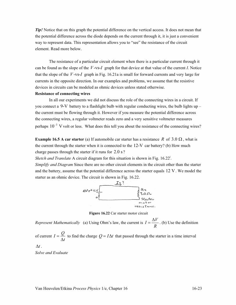
perhaps 10–3 V volt or less. What does this tell you about the resistance of the connecting wires? Example 16.5 A car starter (a) If automobile car starter has a resistance R of 3.0 : , what is the current through the starter when it is connected to the 12-V car battery? (b) How much charge passes through the starter if it runs for 2.0 s ? Sketch and Translate A circuit diagram for this situation is shown in Fig. 16.22i. Simplify and Diagram Since there are no other circuit elements in the circuit other than the starter and the battery, assume that the potential difference across the starter equals 12 V . We model the starter as an ohmic device. The circuit is shown in Fig. 16.22.
Figure 16.22 Car starter motor circuit
Represent Mathematically (a) Using Ohm’s law, the current is VIR'
. (b) Use the definition
of current QI
t '
to find the charge Q I t ' that passed through the starter in a time interval
't . Solve and Evaluate

Van Heuvelen/Etkina Process Physics 1/e, Chapter 16 16-24
12 V 4.0 A3.0
VIR'
:
= 4.0 A.
� �� � � �� �4.0 A 2.0 s 4.0C s 2.0 s 8.0 CQ I t ' .
The units for both quantities are correct. Since the current is quite large, it’s reasonable that such a large electric charge passed through the starter. Try It Yourself: The current through the light bulb in your desk lamp is 0.33A . The effective potential difference across it is 120-V . What is the resistance of the bulb when this particular current is flowing through it? Answer: 360 : . Review question 16.4 How did we learn about Ohm’s law?
18.5 Electric resistance depends on properties of resistor In the previous sections we devised a new physical quantity – electric resistance. In this
section we investigate what causes resistors to have different electric resistance values R. Electric resistance depends on the shape and type of material
A rearranged form of Ohm’s law (VRI'
) provides an operational definition for
determining the electric resistance of a circuit element. Use a voltmeter to measure the potential difference across the circuit element, use an ammeter to measure the current through the circuit element, and then calculate R. This is just a measurement method. It does not help us understand why a resistor has a particular resistance (here we will only discuss ohmic resistors).
What properties of a resistor have an effect on the value of its resistance? Consider again the water flow system with a hose connecting two containers of water. A wider hose should allow more water to pass through a cross section of the hose each second, and a longer hose should allow less water to pass per unit time (due to friction exerted by the walls of the hose on the water.) By analogy, we suspect that the length and the cross sectional area of a wire will affect its electrical resistance. Also, if a resistor is made of a dielectric material, then the current through it will be nearly zero, meaning it has a huge resistance. So, it seems resistance must also depend on the internal properties of the material of which it is made. In fact, experimental investigations of how the resistance of a circuit element depends on its geometric properties (its length L and
cross-sectional area A Sr2 ) are done with the set-up shown in Fig. 16.23 using wires of different lengths and cross-sectional areas. The measuremets yield the data shown in Fig. 16.24. It appears that the resistance increases in proportion to the wire’s length (Fig. 16.24a) and inversely proportional to the cross sectional area (Fig.16.24b) – similar to what we expected based on the water analogy.

Van Heuvelen/Etkina Process Physics 1/e, Chapter 16 16-25
R lv and 1RA
v
To investigate how the type of material affects the resistance we can measure the resistance of wires with the same length and cross sectional area but made from different materials. We find that copper and nichrome (a nickel-chromium alloy) wires have the smallest resistance and tungsten wires have the largest resistance.
Figure 16.23 Measuring resistance
Figure 16.24 Wire resistance depends on its length and area
The dependence of the resistance R of a resistor on the type of material of which it is
made is characterized in terms of a physical quantity called the resistivity U of that material.
Microscopically a material’s resistivity depends on the number of free electrons per atom in the material, the degree of “difficulty” the electrons have moving through the material due to their interactions with it, and other factors. Copper has a low resistivity because of its large concentration of free electrons (two per atom) and the relative lack of difficulty they experience while moving through the copper. On the other hand, the resistivity of glass (a dielectric) is about 1020 times greater than that of copper because it contains so few free electrons. Alternatively, materials are sometimes characterized in terms of another physical quantity called conductivity
V . The conductivity of a material is the inverse of its resistivity ( 1V U ).

Van Heuvelen/Etkina Process Physics 1/e, Chapter 16 16-26
We can assemble an equation for the resistance of a resistive circuit element by combining these three dependencies.
Electric resistance The electric resistance R of a resistive circuit element depends on its geometrical structure (its length L and cross-sectional area A) and on the resistivity U of the
material of which it is made:
lRA
U (16.4)
Tip! The same Greek letter U is used for resistivity and also for the density of a substance. Do
not confuse the two! The resistivities U of various materials are listed in Table 16.6.
Table 16.6 The resistivity � of different materials. Material Resistivity ( m:� , at 20 Cq )
Metals Silver 81.6 10�u
Copper 81.7 10�u Aluminum 82.8 10�u
Dielectrics Ordinary glass 119 10u
Hard rubber 161 10u Shellac 141 10u Wood 8 1210 10�
Body parts Blood 1.5 Lung 20 Fat 25
Human trunk 5 Membrane 175 10u
Geological materials Igneous rocks 2 710 10�
Sedimentary rocks 51 10� Ground water § 10
Tip! The resistivity of the materials in Table 16.6 is provided for a particular temperature. As we know, the resistance of a light bulb is higher when it is hot than when it is cold. This means its resistivity changes with temperature. The resistivity of some other materials, like constantan, does not change that much with temperature.

Van Heuvelen/Etkina Process Physics 1/e, Chapter 16 16-27
In the previous section we found that there is very small potential difference across connecting wires when current is flowing in the circuit. The example below will help you understand why. Quantitative Exercise 16.6 Resistance of connecting wires The connecting wires that we use in electric circuit experiments are usually made of copper. What is the resistance of a 10 cm long
piece of copper connecting wire that has a diameter of 32.0 mm 2.0 10 m� u ?
Represent Mathematically The resistance of a wire is lRA
U . The cross sectional area of the
wire, assuming that it is a circle, is 2A rS . Therefore the resistance is
2 2( / 2)l lRr d
U US S
.
Solve and Evaluate Look up the resistivity of copper using Table 16.6:
8 42 3 2
0.1 m(1.7 10 m) 5.4 10 ( / 2) (1.0 10 m)
lRd
US S
� �� u :� u :
u.
This is a tiny resistance. If the current through this wire were 1 A, the potential difference across it would be
'V IR 1.0 A� � 5.4 u10�4:� � 5.4 u10�4 V .
This is a small potential difference. Typical light bulb filaments have resistances of 100 – 300 : and will therefore have a potential difference of 100 – 300 V across them if the current through them is 1 A. This result is very important. If the connecting wires are not too long or too thin, their resistances and therefore the potential difference across them can be assumed to be zero. Try It Yourself: Suppose a power line from the power plant to your home had the same cross sectional area as in this example but was 50 km long. What is the resistance of the power line and the potential difference across it if the current through it is 1 A? Answer: 270 :, 270 V. Power lines are actually designed with much greater cross-sectional areas so that their resistance is kept low. Tip! There are two mathematical expressions that can be used to determine the resistance of a
resistor: VRI'
and lRA
U . The former is an operational definition and the latter represents
a cause-effect relationship. More about resistivity
Recall the microscopic structure of a metal: a crystal structure of metal atoms whose outer electrons, rather than remaining bound to the atoms, are free to roam throughout the bulk of

Van Heuvelen/Etkina Process Physics 1/e, Chapter 16 16-28
the metal. At the beginning of the 20th century, the most popular model of metals explained that these free electrons behaved similarly to an ideal gas of molecules, moving randomly in all directions inside the metal. The free electrons were in some ways like a cloud of mosquitoes on a calm day. Every mosquito moved inside the cloud but the cloud itself was stationary. If the wind started blowing, the whole cloud started drifting in the direction of the wind, because of the force of the wind exerted on the mosquitoes. They continued to buzz around inside the cloud as it drifted in the direction of the wind. (Fig.16.25a)
Figure 16.25 Microscopic motion of electrons in a metal
The free electrons inside a metal were thought to behave similarly when a non-zero
-fieldEG
was present within the metal. They start accelerating in the direction opposite the
direction of the -fieldEG
(Fig. 16.25b.) When an electron collides with an ion, the electron slows
down briefly, and then starts accelerating again in the direction opposite the EG
field. This collective motion of the electrons is an electric current. The average speed of this collective motion is much smaller than the average speed of the electron’s random motion.
This suggests a microscopic explanation for resistance. As the electrons drift through the wire, they collide with the metal ions. In addition, these collisions result in an increase in the internal energy of the metal as the ions vibrate more vigorously. These vibrating ions become even more of an obstacle for the electrons. That explains why a hotter metal has a higher resistivity than a cooler one. This hundred-years old model sounds quite promising. It is known as the Drude model, first suggested by Paul Drude in 1900. Although later, with the development of quantum mechanics, this model was found to be inadequate for explaining many properties of metals, it is still a concrete and convenient way to visualize the reasons for electric resistance and the mechanism of transforming electrical energy to internal thermal energy. Superconductivity
In the early 1900s a Dutch physicist named Kamerlingh Onnes was attempting to liquefy helium, the only gas that had not yet been liquefied at that time. In 1908 he achieved the desired result – the helium condensed from a gas to a liquid at 4.2 K. Onnes continued experimenting with helium and focused his attention on measuring the electric resistivity of materials at this low temperature. Many physicists, including Lord Kelvin himself, thought that at very low

Van Heuvelen/Etkina Process Physics 1/e, Chapter 16 16-29
temperatures, electrons in metals should completely stop moving, thus making the resistivity infinite. Others, including Onnes, thought that maybe the resistivity decreased with temperature and would eventually become zero at zero K. (Fig. 16.26a)
Figure 6.26 (a) Predictions about low temperature resistivity and (b) measured value for mercury
In 1911 Onnes made an electric circuit by connecting the terminals of a battery to a
sample of mercury and measured the current through it and the potential difference across it. This resulted in a current through the mercury. When Onnes submerged the mercury sample in liquid helium at 4.2 K and repeated his measurement, he found the current still flowing through the sample but the potential difference across it dropped to zero – this meant that the resistance of the sample was zero. Basically he observed that the resistivity of mercury became zero not at 0 K, but at 4.2 K. (Fig.16.26b). Onnes had discovered what became known as superconductivity. Superconductivity was a surprising result that was not predicted and wasn’t successfully explained until about fifty years later. The explanation is based on ideas from quantum mechanics and is beyond the scope of this book. But the main idea is that at very low temperatures, the electrons no longer interact at all with the vibrations of the metal lattice ions. Without any interactions to disrupt the flow of electrons, they continue to flow forever.
In the mean time, Onnes and other physicists continued experimenting with different metals and found that many of them including aluminum and tin become superconductors at very low temperatures, but that others, including gold and silver, never do.
Unfortunately, the temperatures at which the superconductivity was achieved were very low, never above 20 K. This made the practical applications of superconductivity very difficult. For more than 70 years physicists tried to find materials with much higher critical temperatures

Van Heuvelen/Etkina Process Physics 1/e, Chapter 16 16-30
(the temperature at which a material becomes a superconductor) so that they could perhaps be used in place of wires at more ordinary temperatures. The possibility of this seemed grim since at the time the existing ideas of superconductivity predicted that superconductivity was impossible above approximately 30 K.
In 1986 a seemingly impossible event occurred. Bednorz and Muller observing superconductivity in a material at a temperature of 35 K. The material they used was not even a metal. It was a complex carbon-based ceramic compound. With this as guidance, physicists managed to raise the high-temperature superconductivity record to 95 K. In 1993, a complex ceramic compound consisting of thallium, mercury, copper, barium, calcium, and oxygen was found to have a critical temperature of 138 K. In 2008 a new family of metal-based superconductors was discovered, and in October of 2009 a superconductor belonging to this family was found to have a critical temperature of 254 2 Kr . This is 19 C� q , or 2 F� q . The goal of discovering a room temperature superconductor no longer seems impossible. These materials are very complex and it is not clear at this time how to manufacture them in large quantities or how to make sturdy circuit elements from them.
The applications of superconductors are numerous. One is transportation by magnetic levitation, the unique property of superconductors to float suspended above magnets. Superconductors can also be used to make super strong electromagnets. Using superconductors to transmit information will bypass limitations on data rates caused by electric resistance. Finally, superconductors can be used as a basis for supersensitive thermometers. Semiconductors
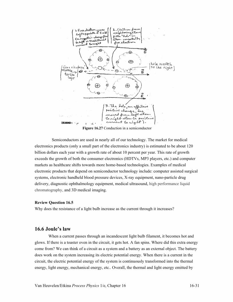
We’ve learned that the electric resistance of metal conductors increases with temperature. However, there are other types of conducting materials whose resistivity has the opposite dependence: it decreases with increasing temperature. Silicon is an example. When silicon is cooled to near 0 K, it has practically infinite resistance. As its temperature increases, its resistance decreases. Unlike in metals, the outer electrons of silicon atoms are not free – they are more tightly bound to the atoms but still can be exchanged between different atoms. When the temperature of a silicon crystal increases, some of the electrons do become free leaving behind a positively charged ion in the crystal lattice. This positively charged ion is called a hole (Fig.
16.27.) If charged objects outside the silicon crystal are used to produce a non-zero -fieldEG
within the silicon, these newly freed conduction electrons accelerate in a direction opposite the
-fieldEG
, similar to the way they do in metals. In addition, the electrons of atoms next to the holes can move into the hole. The atom where the electron came from is now the hole. In effect, these positively charged holes behave similarly to positively charged objects, accelerating in the
direction of the -fieldEG
. Because the number of conduction electrons and holes increase as the temperature of the semiconductor increases, it explains why the resistance of a semiconductor decreases with increasing temperature.
Van Heuvelen/Etkina Process Physics 1/e, Chapter 16 16-31
Figure 16.27 Conduction in a semiconductor
Semiconductors are used in nearly all of our technology. The market for medical
electronics products (only a small part of the electronics industry) is estimated to be about 120 billion dollars each year with a growth rate of about 10 percent per year. This rate of growth exceeds the growth of both the consumer electronics (HDTVs, MP3 players, etc.) and computer markets as healthcare shifts towards more home-based technologies. Examples of medical electronic products that depend on semiconductor technology include: computer assisted surgical systems, electronic handheld blood pressure devices, X-ray equipment, nano-particle drug delivery, diagnostic ophthalmology equipment, medical ultrasound, high performance liquid chromatography, and 3D medical imaging. Review Question 16.5 Why does the resistance of a light bulb increase as the current through it increases?
16.6 Joule’s law When a current passes through an incandescent light bulb filament, it becomes hot and glows. If there is a toaster oven in the circuit, it gets hot. A fan spins. Where did this extra energy come from? We can think of a circuit as a system and a battery as an external object. The battery does work on the system increasing its electric potential energy. When there is a current in the circuit, the electric potential energy of the system is continuously transformed into the thermal energy, light energy, mechanical energy, etc.. Overall, the thermal and light energy emitted by

Van Heuvelen/Etkina Process Physics 1/e, Chapter 16 16-32
light bulbs, toasters, hair dryers, etc, comes from the battery. Our goal in this section is to determine the rate at which electric potential energy is transformed into thermal energy and other forms of energy inside a resistive device. In Chapter 6 we learned that power is the physical quantity for the rate of energy transformation. In this case it’s the rate at which the thermal energy of a resistive device increases:
thermalUPt
'
'.
The amount by which thermalU increases is equal to the amount that the electric potential energy of
the system qU decreases. Therefore:
qUP
t�'
'
.
As electrons (total electric charge Q� ) travel through the resistive device, they travel from the
side at low -fieldV value to the side at high -fieldV value. This movement of electrons results
in a change in the electric potential energy of the system qU q V Q V' ' � ' . Therefore:
Q V QP V I V
t t'
' '' '
This relationship between the current I through the resistive device, the potential difference V' across it, and the rate of energy transformation P is known as Joule’s Law:
P I V ' (16.5)
Does the above have the correct power units (watts = 1 W = 1 J/s)? C J JA V = = Ws C s
� �
The units match. Let’s test Joule’s law. Connect a battery to an un-insulated coil of wire and insert the wire
in a cup of water (Fig.16.28). Energy flows through heating from the wire into the water. We can use Joule’s law to predict the change in temperature of the water during a chosen time interval, and then see if it is consistent with the results of the experiment.
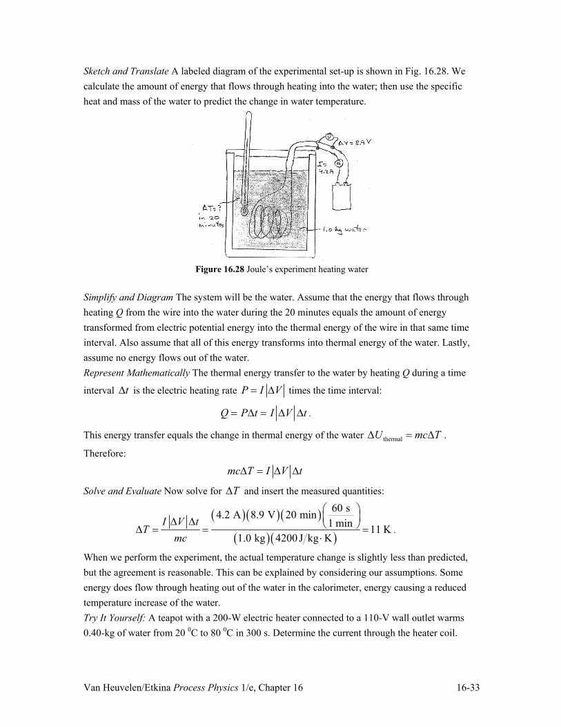
Example 16.7 Testing Joule’s law A coil of constantan wire is placed in an insulated container (called a calorimeter) that is filled with 1.0 kg of water. The coil is connected to a battery. A thermometer in the calorimeter measures the water temperature; an ammeter and a voltmeter measure current through the wire and the potential difference across it. The potential difference across the wire is 8.9 V and the current through it is 4.2 A. Predict how much the temperature of the water will change in 20 minutes.
Van Heuvelen/Etkina Process Physics 1/e, Chapter 16 16-33
Sketch and Translate A labeled diagram of the experimental set-up is shown in Fig. 16.28. We calculate the amount of energy that flows through heating into the water; then use the specific heat and mass of the water to predict the change in water temperature.
Figure 16.28 Joule’s experiment heating water
Simplify and Diagram The system will be the water. Assume that the energy that flows through heating Q from the wire into the water during the 20 minutes equals the amount of energy transformed from electric potential energy into the thermal energy of the wire in that same time interval. Also assume that all of this energy transforms into thermal energy of the water. Lastly, assume no energy flows out of the water. Represent Mathematically The thermal energy transfer to the water by heating Q during a time
interval 't is the electric heating rate P I V ' times the time interval:
Q P't I 'V 't .
This energy transfer equals the change in thermal energy of the water thermalU mc T' ' .
Therefore:
mc T I V t' ' '
Solve and Evaluate Now solve for T' and insert the measured quantities:
� �� �� �
� �� �
60 s4.2 A 8.9 V 20 min1 min 11 K
1.0 kg 4200J kg KI V t
Tmc
§ ·¨ ¸' ' © ¹' �
.
When we perform the experiment, the actual temperature change is slightly less than predicted, but the agreement is reasonable. This can be explained by considering our assumptions. Some energy does flow through heating out of the water in the calorimeter, energy causing a reduced temperature increase of the water. Try It Yourself: A teapot with a 200-W electric heater connected to a 110-V wall outlet warms 0.40-kg of water from 20 0C to 80 0C in 300 s. Determine the current through the heater coil.

Van Heuvelen/Etkina Process Physics 1/e, Chapter 16 16-34
Answer: The heating needed to warm the water is 51.0 10 JQ mc T ' u . The current through
the heater coil is 3.1 AQIV t
' '
.
Tip! The symbol Q is used to represent heating (an energy transfer process), and also to
represent electric charge. This can lead to confusion. Always be sure what quantity each symbol in an equation represents.
Similar experiments to the one described in Example 16.7 were performed by James
Joule in the 1850s. Later, Heinrich Lenz (1804-1865) and Antoine Becquerel (1852-1908) repeated the experiments using alcohol instead of water. After a great deal of testing, physicists agreed to call the expression for the rate of electric potential energy conversion to thermal energy Joule’s law. Joule’s law is sometimes called the Joule-Lenz law since it was later independently discovered by Heinrich Lenz (you will encounter this Russian physicist again in Chapter 18). Joule’s law The rate P at which electric potential energy is transformed into thermal energy
thermalU' in a resistive device is equal to the magnitude of the potential difference ǻV across the
device multiplied by the current I through the device:
thermalUP I Vt
' '
' (16.5)
Joule’s law can be written in two alternate forms using Ohm’s law I 'VR
:
� �� �
2
2
P I V I IR I R
VVP I V VR R
'
''§ · ' ' ¨ ¸© ¹
(16.6)
Quantitative Exercise 16.8 Making a space heater You want to build a 1200-W heater to warm the study in your house. It will plug into a standard wall socket, which results in a 120-V effective potential difference across the heater. You use nichrome wire common in electric heaters, as its resistivity does not change significantly with temperature. The resistivity of the nichrome wire is
61.0 10 m�u :� and its radius is 0.40 mm. How long should the wire be to have the desired power output? Represent Mathematically Use one of the three forms of Joule’s law [Eq. (16.6)] to find the wire’s resistance:

Van Heuvelen/Etkina Process Physics 1/e, Chapter 16 16-35
2VRP
' .
Next, use Eq. (16.5) to relate the wire’s resistance to the length of wire: lRA
U
Now set the right side of the first equation equal to the right side of the second equation: 2l V
A PU '
Solve and Evaluate Solve for length l and insert values: 2 2 –3 2
–6
(120 V) (0.40 10 m) = 6.0 m(1200 J/s) (1.0 10 m)
V AlP
SU
' u
u :�.
Let’s check the units:
V2m2
Js:�m
JC
§©
·¹
2
m
Js
VA
§©
·¹
J2 �m
C2 Js
J CC s
§©
·¹
J2 �m
C2 J2
ss
C2
§©
·¹
m
The units are correct, and 6.0 m is a reasonable length for a wire. We can also check limiting cases. If the resistivity ȡ of the wire is very large, you need a much shorter wire to achieve the desired power output. If its radius is larger, its resistance is smaller. Hence, you need a longer wire. Try It Yourself: Suppose you don’t have 0.40-mm radius nichrome wire but instead have 0.80-mm radius nichrome wire. Now, how long should the wire be? Answer: 24 m.
Joule’s law can also explain some phenomena that we encounter every day. You buy
light bulbs in stores according to their labeled “wattage”—for example, a 60-W light bulb. What is the difference between a 60-W light bulb and a 100-W light bulb? How can one put a power rating on a bulb when it depends on the current flowing through it? The labeling of the light bulbs we buy in stores assumes that you use them in the circuits where the potential difference across them is 120 V (this is the potential difference across them when they are used in the US homes). When the potential difference across them is different, the power is different. However, this rating is useful for us if we want to understand the difference between those two bulbs. Let’s use Joule’s law to determine the resistance of this 60-W bulb (when the potential difference across it is 120 V .).
� � � � � �2 2 2120 V
240 60 W
V VP R
R P' '
� :

Van Heuvelen/Etkina Process Physics 1/e, Chapter 16 16-36
The resistance of a 100-W bulb turns out to be 144 : . Interestingly, the bulb with the higher power rating has a smaller resistance. This makes sense. A bulb with a lower resistance will result
in a larger current through it, and since P I V ' , a larger current through it results in a larger
power output. If you look carefully at the filaments of the two bulbs while they are off, you see that the 60-W bulb has a thinner and therefore more resistive filament (assuming that the filaments are made of the same material.) Paying for electric energy
Electric power companies charge their customers according to the amount of electrical potential energy that is transformed into other energy forms in the devices that customer uses. The unit that is used by the power company to quantify this is not the joule. Instead they use an energy unit called the kilowatt-hour. A kilowatt-hour ( kW h� ) is the electrical potential energy that a 1000-W device transforms to other energy forms in a time interval of one hour. The 2008 average residential cost in the US was $0.11 per kW h� .
Review question 16.6 Suppose two light bulbs of different resistance have the same potential difference across them. Is the rate of transformation of electric potential energy into thermal energy higher in the bulb with more resistance or in the bulb with less resistance? Explain.
16.7 Kirchhoff’s rules Most electric circuits are more complex than the ones studied so far. They consist of
combinations of many resistive elements, switches, one or more power supplies, and a variety of other circuit elements. For example, the electronic circuit shown in Fig.16.29 represents a very simple model of the wiring in your home (the ground in the figure means zero potential). You may have had the experience that if too many electrical devices in your home are on simultaneously, a circuit breaker will stop the current through all the devices. What is the purpose of this safety feature? To answer this question, we need to develop techniques to determine the electric current through each circuit element in these more complicated circuits.

Van Heuvelen/Etkina Process Physics 1/e, Chapter 16 16-37
Figure 16.29 Home wiring system
Kirchhoff's Loop Rule
The current (the direction that positively-charged particles would move) in the circuit shown in Fig. 16. 30a is counterclockwise. We know that negatively charged electrons actually move in the opposite direction. It is easier to think in terms of moving positive charges, and all results end up being the same.
Figure 16.30 A trip around an electric circuit
Let us use a very simplified model of just one electrically charged particle with the
charge of �q moving through a circuit. Consider first the change in potential as it moves from
position A through the battery. For a positive charge, the trip across the battery from the negative to positive terminal of the battery is like being pulled up a hill whose height is in units of volts—see Fig. 16.30b. The positive charge prefers to stay at the negative terminal. During the rest of the trip, the charge moves through resistors and low resistance wires. If the charge is moving in the direction of the current from position C to position D, the change in potential across this resistance or bulb is VD – VC ² V –IR , the negative sign indicating a lower potential at D
than at C. The motion of the charge is analogous to the fall of a skydiver in the Earth's
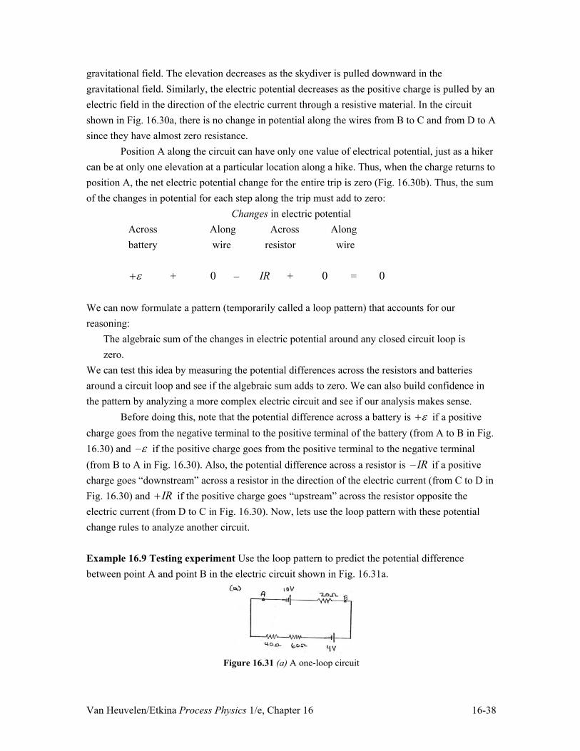
Van Heuvelen/Etkina Process Physics 1/e, Chapter 16 16-38
gravitational field. The elevation decreases as the skydiver is pulled downward in the gravitational field. Similarly, the electric potential decreases as the positive charge is pulled by an electric field in the direction of the electric current through a resistive material. In the circuit shown in Fig. 16.30a, there is no change in potential along the wires from B to C and from D to A since they have almost zero resistance.
Position A along the circuit can have only one value of electrical potential, just as a hiker can be at only one elevation at a particular location along a hike. Thus, when the charge returns to position A, the net electric potential change for the entire trip is zero (Fig. 16.30b). Thus, the sum of the changes in potential for each step along the trip must add to zero:
Changes in electric potential Across Along Across Along battery wire resistor wire
�H + 0 – IR + 0 = 0 We can now formulate a pattern (temporarily called a loop pattern) that accounts for our reasoning:
The algebraic sum of the changes in electric potential around any closed circuit loop is zero.
We can test this idea by measuring the potential differences across the resistors and batteries around a circuit loop and see if the algebraic sum adds to zero. We can also build confidence in the pattern by analyzing a more complex electric circuit and see if our analysis makes sense.
Before doing this, note that the potential difference across a battery is �H if a positive charge goes from the negative terminal to the positive terminal of the battery (from A to B in Fig. 16.30) and –H if the positive charge goes from the positive terminal to the negative terminal (from B to A in Fig. 16.30). Also, the potential difference across a resistor is – IR if a positive charge goes “downstream” across a resistor in the direction of the electric current (from C to D in Fig. 16.30) and �IR if the positive charge goes “upstream” across the resistor opposite the electric current (from D to C in Fig. 16.30). Now, lets use the loop pattern with these potential change rules to analyze another circuit. Example 16.9 Testing experiment Use the loop pattern to predict the potential difference between point A and point B in the electric circuit shown in Fig. 16.31a.
Figure 16.31 (a) A one-loop circuit

Van Heuvelen/Etkina Process Physics 1/e, Chapter 16 16-39
Sketch and Translate A labeled circuit diagram is shown in Fig. 16.31a. The potential difference across a resistor can be determined using the current through it ( V IR' r ). Thus, to determine the potential difference between points A and B, we need to determine the current in the circuit. We use the loop pattern for this. Simplify and Diagram Assume that the wires and batteries have very small resistance (zero resistance) compared to the resistances of the resistors. We also need to decide on the direction of the current. The 10-V battery, having the larger emf than the 4-V battery, will cause a clockwise current, drawn in Fig. 16.31b.
Figure 16.31 (b)
Represent Mathematically Start at point A in Fig. 16. 31b and apply the loop pattern moving clockwise:
'V10 V � 'V20 : � 'V4 V � 'V60 : � 'V40 : 0
� �10 V� �Š I(20 :) � �4 V� �Š I(60 :) Š I(40 :) 0
Notice that the potential difference across the 4.0-V battery was negative since we moved from the positive to the negative terminal of that battery. Also the potential differences across the resistors were negative as we moved across these resistors clockwise downstream in the direction of the electric current. Solve and Evaluate We can now determine the current:
10.0 V 4.0 V 0.050 A
20 60 40 I �
:� :� :
To determine the potential difference from A to B, we follow the circuit along any continuous path from A to B and add the potential differences across each element in the circuit along that path. There are two possible paths. We first move clockwise from A through the 10.0-V battery and 20-: resistor:
'VAB 'V10 V � 'V20 : �10 V Š (0.050 A)(20 :) �9.0 V
The -fieldV value at B is 9.0 V higher than at A. We can also calculate the potential change from A to B by moving counterclockwise
upstream through the 40 : and 60 : resistors (opposite the current) and through the 4.0-V battery from its negative to positive terminal.

Van Heuvelen/Etkina Process Physics 1/e, Chapter 16 16-40
'VAB 'V40 : � 'V60 : � 'V4 V
�(0.050 A)(40 :) � (0.050 A)(60 :) � 4.0 V �9.0 V
The potential difference from A to B is the same no matter which path we take. Now we take a voltmeter and connect its terminals to A and B (its negative terminal at A and its positive terminal at B). The voltmeter reads about +9.0 V. Try It Yourself: Suppose in the previous circuit, there was an open switch inserted in the vertical wire on the left side before position A. Now, apply the loop pattern to determine the potential difference across the switch. Answer: With the switch in the circuit, the electric current will be zero. The loop pattern applied going clockwise starting at A is then:
'V10 V � 'V20 : � 'V4 V � 'V60 : � 'V40 : � 'Vswitch 0
� �10 V� �Š 0(20 :) � �4 V� �Š 0(60 :) Š 0(40 :) � 'Vswitch 0
or 'Vswitch Š6 V . The top of the switch closer to the 10-V battery will be at a lower potential.
Tip! To indicate the signs of the electric potential changes across the resistors in the previous example, we chose and indicated in the circuit drawing the direction we thought the current traveled. If we choose incorrectly, there is no problem as when the calculations are done, the current will be negative. But in order to apply the loop pattern, we must indicate a current direction in the circuit diagram.
This ‘loop pattern’ that we just devised was first developed in 1845-46 by a German physicist Gustav Robert Kirchhoff (1824-1887). Kirchhoff is known for trying to unify the physics of electrostatics (Chapters 14 and 15) and the physics of electric circuits. The pattern that we just devised and that has now been tested many times is known as Kirchhoff’s loop rule.
Kirchhoff’s loop rule The sum of the electric potential differences V' across the circuit elements that make up a closed path (called a loop) in a circuit is zero.
Loop
0V' ¦ (16.7)
When using the loop rule you need to follow these sign conventions: x The potential difference across a resistor is ŠIR when the loop traverses the resistor in the
direction of the current through it and � IR when the loop traverses the resistor in the direction opposite the current through it.
x The potential difference across a battery (assuming zero internal resistance—discussed shortly) is �H when the loop traverses the battery from its negative terminal to its positive

Van Heuvelen/Etkina Process Physics 1/e, Chapter 16 16-41
terminal and ŠH when the loop traverses the battery from its positive terminal to its negative terminal.
Kirchhoff's Junction Rule Our goal for this section was to develop ideas that would let us analyze more complex
circuits. We developed the loop rule for a circuit with only one loop. However, many electric circuits have several loops. (Fig. 16.32) In multi-loop circuits, the positively charged objects moving along a wire can arrive at a junction where several wires meet. What happens at these junctions? Going back to our analogy with water flowing in pipes, when water reaches a Y-junction, it splits with some water flowing along one pipe and the rest flowing along the other (Fig. 16. 33). What is important is that the water cannot disappear and cannot “pile up”; thus the rate at which water flows into the junction must equal the rate at which it flows out.
Figure 16.32 A multi-loop circuit
Figure 16.33 Water flow rate in equals flow rate out
Tip! In Fig. 16.33 Q means water flow rate (review by reading chapter 11). The same letter is
used for the electric charge and for the energy transferred through heating. Electric current behaves in much the same way. Since it is comprised of individual
physical objects in collective motion (much like water is comprised of individual molecules), those objects cannot vanish or be created out of nothing (electric charge is a conserved quantity). The rate of electric charge flowing (the electric current) into the junction must equal the rate of electric charge flowing out.
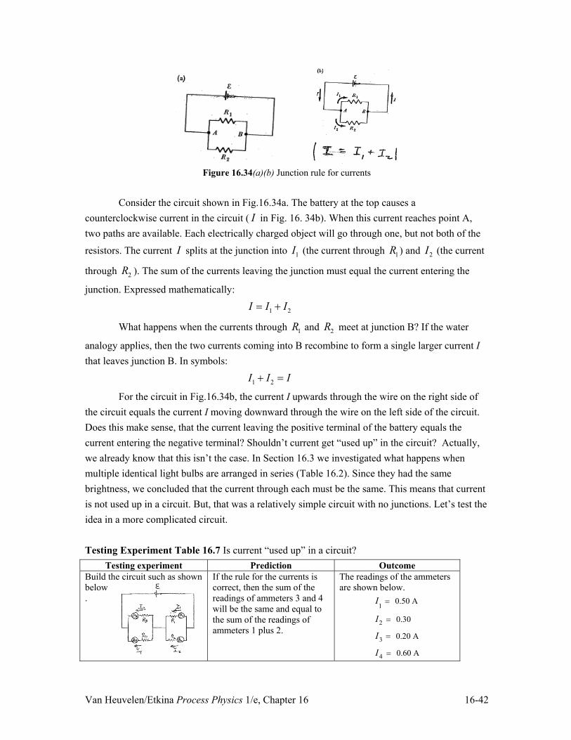
Van Heuvelen/Etkina Process Physics 1/e, Chapter 16 16-42
Figure 16.34(a)(b) Junction rule for currents
Consider the circuit shown in Fig.16.34a. The battery at the top causes a
counterclockwise current in the circuit ( I in Fig. 16. 34b). When this current reaches point A, two paths are available. Each electrically charged object will go through one, but not both of the
resistors. The current I splits at the junction into 1I (the current through 1R ) and 2I (the current
through 2R ). The sum of the currents leaving the junction must equal the current entering the
junction. Expressed mathematically:
1 2I I I �
What happens when the currents through 1R and 2R meet at junction B? If the water
analogy applies, then the two currents coming into B recombine to form a single larger current I that leaves junction B. In symbols:
1 2I I I�
For the circuit in Fig.16.34b, the current I upwards through the wire on the right side of the circuit equals the current I moving downward through the wire on the left side of the circuit. Does this make sense, that the current leaving the positive terminal of the battery equals the current entering the negative terminal? Shouldn’t current get “used up” in the circuit? Actually, we already know that this isn’t the case. In Section 16.3 we investigated what happens when multiple identical light bulbs are arranged in series (Table 16.2). Since they had the same brightness, we concluded that the current through each must be the same. This means that current is not used up in a circuit. But, that was a relatively simple circuit with no junctions. Let’s test the idea in a more complicated circuit. Testing Experiment Table 16.7 Is current “used up” in a circuit?
Testing experiment Prediction Outcome Build the circuit such as shown below.
If the rule for the currents is correct, then the sum of the readings of ammeters 3 and 4 will be the same and equal to the sum of the readings of ammeters 1 plus 2.
The readings of the ammeters are shown below.
I1 0.50 A
I2 0.30
I3 0.20 A
I4 0.60 A

Van Heuvelen/Etkina Process Physics 1/e, Chapter 16 16-43
Conclusion As we see, the current does not get used up when it passes through resistors. But resistors get warm. It’s not because current is “used up” in them. It is the electric potential energy of the system being transformed into thermal energy of the resistive circuit elements. As this is happening, the battery is continually doing work on the system keeping its electric potential energy constant.
We can summarize this splitting and joining of currents at junctions as what is known as Kirchhoff’s junction rule. Kirchhoff's junction rule The total rate at which electric charge enters a junction equals the total rate at which electric charge leaves the junction:
Sum of currents into junction = Sum of currents out. In symbols:
In Out
I I ¦ ¦ (16.8)
A note about wording
In every day life people talk about “electricity.” Sometimes they say that electricity flows, sometimes they talk about using electricity to heat buildings, and sometimes they say that electricity comes out of a plug in the wall. When they say that electricity flows, they mean the flow of charged objects in wires (electric current); when they talk about heating with electricity, they mean electric potential energy being transformed into thermal energy then flowing through heating into the environment; and when they talk about wall sockets, they refer to a 120 V effective potential difference across any appliance plugged into this socket. When you use the word ‘electricity’, make sure you understand what this word means in a particular situation.
Figure 16.35 (a) A battery with internal resistance
Internal resistance In the circuits analyzed so far, we assumed that the potential difference across a battery
with emf H = 9.0 V is in fact 9.0 V. Is that always true? Consider a H = 9.0 V battery connected to commercial resistors of different resistances R one at a time (Fig. 16.35a). Then, measure the current through each resistor. Then repeat the experiment with a 4.5 V battery. We
expect the current through the resistor to be I RH .

Van Heuvelen/Etkina Process Physics 1/e, Chapter 16 16-44
Table 16.8 reveals an interesting pattern. The measured current I through the resistor does not equal the predicted current H /R. According to the loop rule
�H – IR 0 Thus, the emf H of the battery is not the same as the potential difference IR across the resistor. The discrepancy between the prediction and the measured current is bigger when there is a larger current through the battery.
It is possible to represent this pattern quantitatively. If the current through the resistor
were predicted using I1
HR �1.0 :
for the 9.0-V
battery and I2
HR � 0.7 :
for the 4.5-V battery
(check this statement by using it for the values of I in the table), this current would be consistent with the outcomes. It looks like a battery is also a resistive device, and therefore adds a little resistance to the circuit (the 1.0 : and 0.7 : in the above equations). This resistance is called the internal resistance of the battery. Thus, a more accurate way to model a battery is by including its internal resistance as shown in Fig. 16.35b.
Figure 16.35 (b) A battery with internal resistance
We can insert in the above equations the symbol r for the internal resistance of the
battery to get:
I HR � r
Rearranging this, we have:
�H � Ir � IR 0
Table 16.8 Relationship between battery emf and current through the circuit
H 9.0 V battery Resistance R 5 : 10 : 20 :Predicted current
H /R 1.8 A 0.90 A 0.45 A
Measured current
I 1.5 A 0.81 A 0.43 A
Potential across R
IR 7.5 V 8.1 V 8.6 V
H = 4.5-V battery Resistance R 5 : 10 : 20 : Predicted current
H / R/R
0.90 A 0.45 A 0.23 A
Measured current
I 0.79 A 0.42 A 0.22 A
Potential across R
IR 4.0 V 4.2 V 4.4 V

Van Heuvelen/Etkina Process Physics 1/e, Chapter 16 16-45
The internal resistance of the battery explains why batteries sometimes feel warm to the touch after they have been operating for a while. Another way to understand this is to rearrange the above equation as follows:
H � Ir IR� 'Vbatt IR
where battV IrH' � is the potential difference across the battery. Notice that whenever there is
a current through the battery, the potential difference across it is less than its emf; how much less depends on the current through the battery. When there is no circuit attached to the battery (no
current), then the potential difference across it equals its emf. If r R� , then 'Vbatt | H .
Tip! Notice that if r R� , then 'Vbatt | H . It becomes reasonable to assume the internal
resistance of the battery is zero and just use the battery emf İ as the potential difference across its terminals.
We can use the data in Table 16.8 to estimate the internal resistance of the 9.0 V battery. Use the first data point from the table (H 9.0 V , R =5.0 : , and I = 1.5 A ) and the
equation I H
R � r to determine r :
9.0 V - (1.5 A)(5.0 ) 1.0
1.5 AIRr
IH � :
: .
We can check this result using another data point, for example from the second column in Table 16.8:
9.0 V - (0.81 A)(10 ) 1.1
0.81 AIRr
IH � :
: .
It appears that the internal resistance of the 9.0 V battery used in the Table 16.8 experiments is about 1.0 : . Usually commercial resistors are thousands of ohms or more. Thus, the internal resistance of the battery can be considered zero. Short circuit
Imagine that you accidentally connected the terminals of the battery with a connecting wire of approximately zero resistance R 0 (Fig.16.36). The wire melts immediately and the battery becomes very hot and stops working. Notice that when the external resistance R 0 , the current
through the battery is I H
R � r
H0 � r
Hr
. If the internal resistance of the battery is small,
the current becomes large; it burns the connecting wire and destroys the battery. The situation is called a short circuit.

Van Heuvelen/Etkina Process Physics 1/e, Chapter 16 16-46
Figure 16.36 Short circuit
Review question 16.7 Where is the -fieldV value higher: where the current enters a resistor or where it leaves it? Where is the -fieldV value higher: where the current “enters” a conducting wire or where it “leaves” it?
16.8 Series and parallel resistors When one light bulb is turned off in our house, other light bulbs and appliances stay on.
However, if one light bulb goes out in an old-fashioned string of Christmas tree lights, all of the lights go out (this does not happen in contemporary tree lights.) As electric circuits, what is the difference in the arrangement of these bulbs? Resistors in series
Suppose that you arrange three resistors ( R1, R2 , and R3 ) in series with a battery of emf
H (Fig. 16.37a.)
Figure 16.37 Series resistors
We can apply the loop rule to determine the current in the circuit (moving counterclockwise around the circuit starting at the negative terminal of the battery):
1 2 3R R R
Loop
0V V V V VH' ' � ' � ' � ' ¦ .
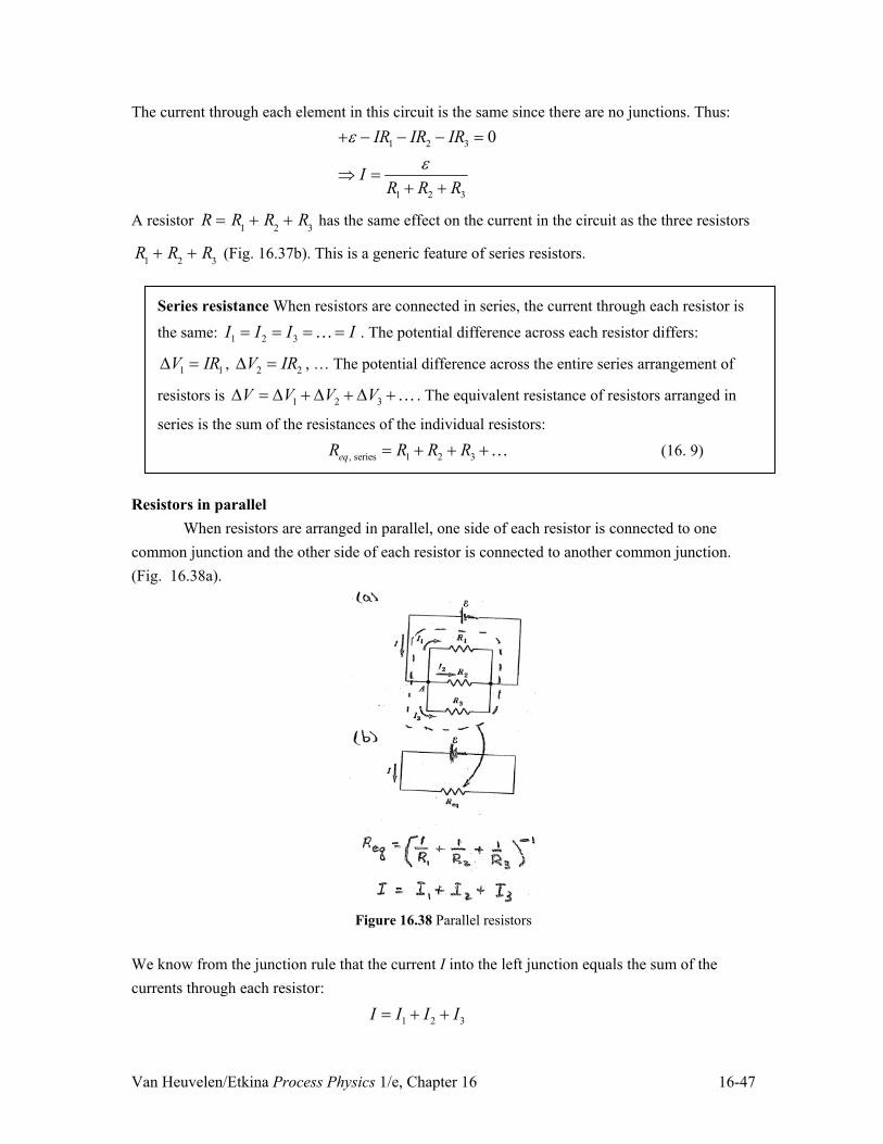
Van Heuvelen/Etkina Process Physics 1/e, Chapter 16 16-47
The current through each element in this circuit is the same since there are no junctions. Thus:
1 2 3
1 2 3
0IR IR IR
IR R R
HH
� � � �
� � �
A resistor R R1 � R2 � R3 has the same effect on the current in the circuit as the three resistors
R1 � R2 � R3 (Fig. 16.37b). This is a generic feature of series resistors.
Series resistance When resistors are connected in series, the current through each resistor is
the same: 1 2 3I I I I ! . The potential difference across each resistor differs:
1 1V IR' , 2 2V IR' , … The potential difference across the entire series arrangement of
resistors is 1 2 3V V V V' ' � ' � ' �! . The equivalent resistance of resistors arranged in
series is the sum of the resistances of the individual resistors:
, series 1 2 3eqR R R R � � �! (16. 9)
Resistors in parallel
When resistors are arranged in parallel, one side of each resistor is connected to one common junction and the other side of each resistor is connected to another common junction. (Fig. 16.38a).
Figure 16.38 Parallel resistors
We know from the junction rule that the current I into the left junction equals the sum of the currents through each resistor:
1 2 3I I I I � �

Van Heuvelen/Etkina Process Physics 1/e, Chapter 16 16-48
What about the other features of this parallel circuit? Consider these questions: (a) How do the potential differences across different resistors compare? (b) How does the current through the first parallel resistor compare to that through the second and
third parallel resistors (suppose that R1 � R2 � R3 )?
(c) Suppose you want to replace the three resistors with a single resistor that causes the same electric current I through the battery. What should the resistance of this single resistor be?
Spend some time now trying to answer these questions on your own. When finished, read on. (a) We learned in Example 16.10 that the potential difference between two points in a circuit is the same regardless of the path taken between those two points. If we choose the points to be the two junctions in Fig. 16.38a, this means that the potential difference across each resistor is the same:
'V1 'V2 'V3 'V
(b) We can use Ohm’s law to determine the current through each resistor:
I1
'VR1
, I2 'VR2
, I3 'VR3
Since the potential difference across each resistor is the same, and since 1 2 3R R R� � , this
means:
1 2 3I I I! !
In other words, in parallel arrangements of resistors, the resistors with smaller resistances have larger currents through them. Tip! Notice that if one resistor in parallel is disconnected, the currents in the other resistors do not
change since I V R ' , and neither V' nor R changed for the other resistor.
(c) According to Kirchhoff’s junction rule:
I I1 � I2 � I3
� I 'VR1
�'VR2
�'VR3
Now, suppose that we replace these three resistors by a single equivalent parallel resistor
, paralleleqR that causes the same current I in the circuit (Fig. 16.38b). This means the current will
be:
I 'V
Req , parallel
Combining these two results we get:

Van Heuvelen/Etkina Process Physics 1/e, Chapter 16 16-49
'VReq , parallel
'VR1
�'VR2
�'VR3
�1
Req, parallel
1R1
�1R2
�1R3
� Req, parallel 1R1
�1R2
�1R3
§
©
·
¹
�1
Tip! Notice the power of (-1) in the equation above!
Figure 16.39 Testing ideas about parallel resistors
To test these ideas about the currents through parallel arrangements of resistors, we can
assemble a circuit with parallel resistors (Fig. 16.39) and use ammeters to measure the current through each resistor and through the battery. The outcome of the experiment is that the smaller the resistance of the resistor, the larger the current through it, as expected. Finally, if we replace the three resistors by a single equivalent resistor according to the above equation:
1 1
, parallel1 2 3
1 1
1 1 1 1 1 12 3
6 3 2 11 66 6 6 6 11
eqRR R R R R R
RR R R R
� �
� �
§ · § · � � � �¨ ¸ ¨ ¸© ¹© ¹
§ · § · � � ¨ ¸ ¨ ¸© ¹ © ¹
The potential difference across each individual resistor is:
'VR I1R 0.30 A� �R (0.30 A) R
'V2 R I2 �2R 0.15 A� �2R (0.30 A) R
'V3R I3 �3R 0.10 A� �3R (0.30 A) R
These are all equal, consistent with our understanding of parallel arrangements. The potential difference across the equivalent parallel resistor is:
'Veq,parallel I �
611
R 0.55 A� �611
R (0.30 A) R

Van Heuvelen/Etkina Process Physics 1/e, Chapter 16 16-50
This equals the potential difference across each individual resistor. This means our expression for the single equivalent parallel resistor is reasonable. We summarize our results about parallel resistance as follows. Parallel resistance: When resistors are connected in parallel:
x The potential difference across each individual resistor is the same:
1 2 3V V V' ' ' !
x The sum of the currents through them equals the total current through the parallel arrangement.
1 2 3I I I I � � �!
x The equivalent resistance of resistors in parallel is: 1
, parallel1 2 3
1 1 1eqR
R R R
�§ ·
� � �¨ ¸© ¹
! (16.10)
Tip! When you connect resistors in series, the equivalent resistance is larger than the largest resistance; when you connect resistors in parallel, the total resistance is less than the smallest resistance.
In Section 16.3 we observed some qualitative patterns involving the brightness of bulbs when they were connected in various arrangements. The next example uses the quantitative understanding of circuits we have developed to explain these patterns. Before you study this example, please review the experiments from Section 16.3. Example 16.10 Brightness of bulbs connected in parallel and in series We will use a battery and two identical light bulbs connected in three different ways: (a) one bulb to a power source, (b) two bulbs in series, and (c) two bulbs in parallel. Determine the equivalent resistance of a single resistor that produces the same current through the battery as in arrangement (b) and arrangement (c) and compare the total electric power output of the bulbs in arrangement (b) and arrangement (c) compared to (a). Sketch and Translate The circuits for the arrangements are shown in Fig. 16.40a, b, c. We replaced the bulbs with the symbols for resistors. To determine the equivalent resistor we need to use the rules for resistors in series and parallel. To determine the power output of the bulbs we use Joule’s law, which means we need to determine the current through each bulb.

Van Heuvelen/Etkina Process Physics 1/e, Chapter 16 16-51
Figure 16.40 Comparing circuits
Simplify and Diagram Assume that the resistance of the connecting wires and the internal resistance of the battery do not affect the current significantly. Also assume that the resistance of the bulbs is constant (meaning, they are ohmic devices.) Represent Mathematically The two identical bulbs in series have an equivalent series resistance:
series 2R R R R � .
The two identical bulbs in parallel have an equivalent parallel resistance: 1 1
parallel1 1 2
2RR
R R R
� �§ · § · � ¨ ¸ ¨ ¸© ¹ © ¹
.
The current in each simplified circuit (with the multiple resistors replaced by a single equivalent resistor) equals the battery emf divided by the circuit equivalent resistance:
eq
IRH
The power output of the equivalent resistor (assumed to be equal to the rate at which electric potential energy is transformed into thermal energy) is:
2eqP I R
Solve and Evaluate (a) The equivalent resistance of circuit (a) is 1R (subscript means 1 bulb.) The
current in this circuit is 1 1I RH . The power output of this circuit is:
2 2 2
21 1 1 1
1
P I R R RR R RH H H§ · § · ¨ ¸ ¨ ¸
© ¹© ¹
(b) The equivalent resistance of circuit (b) is series 2R R . The current in this circuit is:
series 1series
12 2
I IR RH H
This is half the current in circuit (a). This makes sense because adding additional resistors in series increases the total resistance of the circuit. The power output of this circuit is:

Van Heuvelen/Etkina Process Physics 1/e, Chapter 16 16-52
2 2 2
2series series series series 1
series
1 122 2 2
P I R R R PR R RH H H§ · § · ¨ ¸ ¨ ¸
© ¹© ¹
Compared with circuit (a), even though there are two resistors in this circuit, the total power output of circuit (b) is half the power output of circuit (a). This is reasonable since the current in this circuit is half that in circuit (a).
(c) The equivalent resistance of circuit (c) is parallel 2R R . The current in this circuit is:
parallel 1parallel
22
I IR RH H
This is twice the current in circuit (a). This makes sense since adding resistors in parallel decreases the total resistance of the circuit. The power output of this circuit is:
2 2 2
2parallel parallel parallel parallel 1
parallel
2 2 22
P I R R R PR R RH H H§ · § ·
¨ ¸ ¨ ¸¨ ¸ © ¹© ¹
Compared with circuit (a) the total power output of circuit (c) is twice the power output of circuit (a). This is reasonable because when resistors are arranged in parallel they are not affected by each other’s presence.
Notice that the power output of the circuit doubles when you go from one bulb to two parallel bulbs. This means you will be getting twice as much light. On the other hand when you go from one bulb to two series bulbs the power output halves. Each bulb is one-quarter as bright but there are two of them. Also, if one of the series bulbs burns out, the other bulb will go out since there is no longer a complete loop in the circuit. This is another reason why appliances in homes are arranged in parallel. Try It Yourself: You have two small light bulbs. When connected to the same battery alone, bulb 1 is brighter than bulb 2. What will be their relative brightness when they are connected to the battery in series with each other and in parallel? Answer: When in series, bulb 2 is brighter than bulb 1. When in parallel, bulb 1 is brighter than bulb 2. Review Question 16.8 You have two resistors R1 and R2 with R1 > R2. You first connect them in parallel to a battery; then connect them in series to a battery. Compare the equivalent resistance of the parallel and series arrangements with the resistance of each individual resistor.
16.9 Skills for circuit problems The first skill needed for solving electric circuits problems is to draw an electric circuit
diagram you are analyzing. Next, decide which resistors are connected in series and which are in parallel. Following that, you can draw a simplified version of the circuit replacing groupings of

Van Heuvelen/Etkina Process Physics 1/e, Chapter 16 16-53
resistors with single equivalent resistors. From there, you can apply Kirchhoff’s rules to solve the problem. Be sure to include arrows indicating the direction you think the current is moving in each branch of the circuit. This strategy is illustrated in the next example. Example 16.11 Using Kirchhoff’s rules Determine the current in each branch of the circuit shown, and the potential difference between points A and B. Sketch and Translate x Draw the electric circuit described in
the problem statement and label all the known quantities.
x Decide how the resistive elements in the circuit are connected.
x The known information is shown in the circuit diagram. x The resistors are connected in parallel to the battery.
Simplify and Diagram x Decide whether you can neglect the
internal resistance of the battery and/or the resistance in the connecting wires.
x Draw an arrow representing the direction of the electric current in each branch of the circuit (even if you don’t know the directions). If you apply the equations consistently relative to the arrows and any arrows are in the wrong direction, your solution will give a minus sign for those currents.
x Nothing is mentioned about the internal resistance of the battery or the properties of the wires, so we will assume their resistance is negligible.
x Add an arrow and a label for the current in each branch of the circuit. Each arrow points in the direction that we think the current moves in that branch.
Represent Mathematically
x If necessary, replace combinations of resistors with equivalent resistors.
x Apply the loop rule for the potential changes as you move around one or more different loops of the circuit. Each additional loop you choose must include at least 1 branch of the circuit that you have not yet included.
x Once you have included branches, apply the current junction rule for one or more junctions. In total, you will need the same number of independent equations as the number of unknown currents.
x If necessary, use expressions for electric power.
Apply Kirchhoff's loop rule: Loop 1: Start at B and move counterclockwise through the 10-: resistor, then the battery, then back to B.
� 10 :� �I1� 12 V 0
Loop 2: Move counterclockwise from B down through the 20-: resistor and back up through the battery and finally back to B:
� 20 :� �I2� 12 V 0
Apply Kirchhoff's junction rule to get a third independent equation (there are 3 unknown currents):
I I1� I
2
'VA to B: The potential difference between A and B can be found using Ohm’s law:
'VAB 10 :� �I
1 20 :� �I
2
Solve and Evaluate
x Solve the equations for the unknown quantities. Check whether the
We now have three equations for the three unknown currents (I, I1, and I2). The loop 1 and 2 equations can be solved for I1 and I2.

Van Heuvelen/Etkina Process Physics 1/e, Chapter 16 16-54
directions of the current and the magnitude of the quantities make sense.
I1 12 V
10 : 1.2 A
I2 12 V
20 : 0.6 A
Use the junction rule equation to find the total current I: I I
1� I
2 1.8 A
All currents are positive which means the original choices of directions were correct. The potential difference between A and B can now be found
'VAB 10 :� �I
1 20 :� �I
2 12 V
The magnitudes of the currents and VAB
are reasonable.
Try It Yourself: Determine the equivalent resistance of the two resistors in the previous example. Then determine the total current through this equivalent resistance. Is the result consistent with the result using Kirchhoff’s rules?
Answer: , parallel 6.7 eqR : and 1.8 AI , consistent with the answer found using Kirchhoff’s
rules. Example 16.12 Using Kirchhoff’s rules to solve circuit problem (a) Determine the currents in each branch of the circuit shown in Fig. 16.41a. The 9.0-V battery has a 2.0 : ҏҏinternal resistance ҏҏand the 3.0-V battery has negligible internal resistance.
Figure 16.41 (a) Analyze circuit
Sketch and Translate We cannot simplify the circuit using the parallel equivalent resistance equation. This is because there are batteries in two of the branches and the parallel equivalent
resistance applies for branches with resistors only. Since there are three unknown currents, 1I ,
2I , and 3I , we need three independent equations to solve for the currents. We use the loop rule
twice and the junction rule once. Simplify and Diagram Redraw the circuit diagram (Fig. 16.41b) and include symbols and arrows for the chosen directions of the three currents. Assume that the connecting wires have minimal resistance.

Van Heuvelen/Etkina Process Physics 1/e, Chapter 16 16-55
Figure 16.41 (b) Analyze circuit
Represent Mathematically Apply the junction rule to junction A:
1 3 2I I I�
Apply the loop rule for two different loops, First, start at B and move clockwise around the bottom loop:
'V3 V � 'V18 : 0��3.0 V � I2 (18 :) 0
Next, start at B and move counterclockwise around complete outside loop:
'V2 : � 'V9 V � 'V12 : � 'V3 V 0�� I1(2 :) � 9.0 V � I1(12 :) � 3.0 V 0
Notice that we cross the 3.0-V battery from the positive to the negative side, a decrease in -fieldV value.
Solve and Evaluate Using the first loop:
23.0 V 0.17 A18
I :
Using the second loop:
I1
9.0 VŠ3.0 V2 :�12 :
0.43 A
Using the junction A:
3 0.17 A 0.43 A 0.26 AI � �
Since 3I turned out negative it means our initial choice for its direction was incorrect. The
magnitude is still correct though. Try It Yourself: Determine the potential difference from A to B in two ways: 1) through the 18-ȍ resistor and 2) through 12-ȍ resistor, the 2-ȍ resistor, and the 9-V battery. Answer: Both paths give us – 3.0 V.
The next example shows how to use the ideas of equivalent resistance to simplify the analysis of a circuit.

Van Heuvelen/Etkina Process Physics 1/e, Chapter 16 16-56
Example 16.13 Using equivalent resistors to solve a circuit problem Determine the total current I flowing through the battery in Fig. 16.42a. Sketch and Translate A labeled diagram is shown in Fig. 16.42a. To find the current I, first simplify the circuit by combining the resistors into a single equivalent resistor. Simplify and Diagram Assume that the battery and the connecting wires have negligible resistance. The circuit is a combination of series and parallel parts; simplify the circuit in steps. First, replace the parallel 3-ȍ and 6-ȍ resistors by an equivalent resistor (Fig. 16.42b). This simpler circuit has three resistors in series. Replace them with one equivalent resistor. The new circuit is shown in Fig. 16.42c. Once we have a circuit with a single resistor and a single battery, the current through the battery can be determined easily.
Figure 16.42 Finding equivalent resistance
Represent Mathematically First, combine the two resistors in parallel:
Req, parallel =
13 :
+ 1
6 :§©
·¹
�1
Now add this combined resistor to the other resistors in series to determine the equivalent resistance of the entire circuit:
Req 5 :�
13 :
+ 1
6 :§©
·¹
�1
� 8 :
Our simplified circuit has the single equivalent ҏҏresistor attached to the 12-V battery. The current I is:
eq
IRH

Van Heuvelen/Etkina Process Physics 1/e, Chapter 16 16-57
Solve and Evaluate Completing these calculations gives: 1 1 1
, parallel1 1 2 1 3 = + = + = = 2
3 6 6 6 6 eqR� � �
§ · § · § · :¨ ¸ ¨ ¸ ¨ ¸: : : : :© ¹ © ¹ © ¹
5 2 8 15 eqR :� :� : :
12 V 0.80 A15
I :
This value for the current is reasonable given the resistances and battery emf. Try It Yourself: Find the equivalent resistance of the combination of resistors shown in Fig. 16.43.
Figure 16.43
Answer: 8 ȍҠ Review Question 16.9 What does it mean if using Kirchhoff’s rules result in a negative value for a current in a circuit?
16.10 Putting it all together: fuses and human resistance Electric circuits are a ubiquitous part of our everyday lives. In this section we consider
two applications: 1) circuit breakers and fuses, a common feature in homes and buildings and 2) using an electric circuit to model the human circulatory system. Circuit Breakers and Fuses
Although the current through appliances connected to wall sockets (called alternating current, or AC) differs in some ways from the current we studied in this chapter (direct current, or DC), many of the same physics ideas apply to both. A simplified electric circuit for a household wiring system is shown in Fig. 16. 44. As noted earlier in the chapter, household appliances are connected in parallel. When we connect more appliances in parallel, the total resistance of the circuit decreases. As a result, the total current in the main line of the circuit increases. Remember that the main line provides a constant effective potential difference of (120 V). If the current in the main line becomes too great, it can become hot enough (due to its own resistance) that it actually starts a fire. To prevent this, homes have circuit elements called circuit breakers and fuses that are parts of all appliances and of the home wiring system.

Van Heuvelen/Etkina Process Physics 1/e, Chapter 16 16-58
Figure 16.44 Home wiring system
A fuse is a piece of wire made of an alloy of lead and tin. This alloy melts at relatively
low temperature. Thus, when the current through the fuse gets too large to be safe, the increase in thermal energy of the fuse causes the wire to melt. The melted fuse is a gap in the circuit, which causes the current to quickly drop to zero. The fuse must then be replaced. Nowadays, most fuses have been replaced by circuit breakers. There are different kinds of circuit breakers but all of them work on the same principle – when the current in a circuit increases to a critical value, the circuit breaker opens a switch. Circuit breakers are far more convenient than fuses because they are not self-destructive. A circuit breaker that has triggered can quickly be reset instead having to be replaced. Quantitative Exercise 16.14 A 1380-W electric heater, a 180-W heating pad, a 120-W light bulb, and a 1200-W iron are all plugged into wall sockets (Fig.16.45). If the current through the main wire exceeds 20 A, the circuit breaker opens the circuit. Will the circuit breaker open the circuit stopping current flow if all these appliances are in operation at the same time?
Figure 16.45 Will circuit breaker open?

Van Heuvelen/Etkina Process Physics 1/e, Chapter 16 16-59
Represent Mathematically The connecting wires and the circuit breaker have negligible resistance. Consequently there is no electric potential difference across them, and as a result the potential difference across each appliance is 120 V. We can use one form of Joule’s law to determine the current in each appliance:
I P'V
P
120 V.
Kirchhoff’s junction rule can be used to determine the total current through the circuit:
I I1 � I2 � I3 � I4 .
Solve and Evaluate The current through each appliance is:
Heater: 11
1
1380 W 11.5 A120 V
PIV
'
Heating pad: 22
2
180 W 1.5 A120 V
PIV
'
Light: 33
3
120 W 1.0 A120 V
PIV
'
Iron: 44
4
1200 W 10.0 A120 V
PIV
'
The total current through the main wire I is:
1 2 3 4 11.5 A 1.5 A 1.0 A 10.0 A 24.0 AI I I I I � � � � � �
Since the current I exceeds 20 A , the circuit breaker will open the circuit and cause current flow to stop. If the circuit breaker were not included in the circuit and the current exceeded 20 A , the main wires that carry the current through the walls of the house would become too warm and could possibly start a fire. Try It Yourself: Determine the resistance of each of the above appliances. Answer: Heater 10 : ; heating pad 80 :�ҏlight 110 :� iron 12 : Ҡ Resistivity of a human body1
Most of the electric currents in the human body are movements of ions of sodium (Na+), potassium (K+), chlorine (Cl–), and magnesium (Mg2+). The resistivity ȡ of tissue beneath the skin depends on the concentration of these ions and how free they are to move. This tissue is a moderately good conductor with a resistivity of approximately 5 m:� . The resistivity of the skin itself is much greater and protects the body by keeping currents through it small even when a significant potential difference is placed across it, for example when you get shocked touching a doorknob.
1 Adapted from P. H. Baker, "The Nerve Axon," Scientific American, p 74, March (1966).

Van Heuvelen/Etkina Process Physics 1/e, Chapter 16 16-60
Quantitative Exercise 16.15 The human leg as a conductor We can represent the lower leg as a resistor that has a length l 0.3 m and a radius r of about 5 cm = 0.05 m (Fig.16.46). Its resistivity is5 m:� . This resistor is connected to a power supply of emf 120 VH . The power supply has no internal resistance. (a) Estimate the electrical resistance of the tissue under the skin of the lower leg of a human. (b) Determine the current through the leg if connected directly to a wall socket. (WARNING! This is an investigation of a hypothetical situation; you should never do it. We are going to find that the current through the leg is dangerously high.)
Figure 16.46 Resistance of lower leg
Represent Mathematically (a) The resistance of the leg depends on its resistivity and its geometric properties:
2
l lRA r
U US
(b) The current flowing through the leg with a 120-V potential difference across it is I RH .
Solve and Evaluate
R Ul
Sr 2 5 ½ �m� � 0.3 m� �S 0.05 m� �2
= 200 :.
120 V 0.6 A200
IRH
:
This is an extremely dangerous current. A current of just 0.1 A through the heart will likely cause death (see Fig. 16.47). Fortunately, our skin has a much higher resistivity and will protect us to some degree. Nevertheless, you should never touch the wall socket with two hands and never open or try to fix any appliances while it is plugged in.
Figure 16.47 Effect of electric current on human body
Try It Yourself: How would the current be different for a person with: (a) a longer leg; and (b) a thinner leg. Answer: The resistance would be greater and the current smaller in both cases.

Van Heuvelen/Etkina Process Physics 1/e, Chapter 16 16-61
The resistance calculated in the last example came from using the resistivity of internal body tissue, which is a good conductor of electric current. Many more deaths caused by electric shock would occur if it were not for our skin, which is a poor electrical conductor. When skin is dry, its resistance ranges from several thousand ohms to hundreds of thousands of ohms, though if the skin is moist its resistance is smaller. That is why it is so dangerous if a hair dryer or other appliance plugged into a wall socket accidentally falls into a bathtub when someone is taking a bath. The water completes a circuit for the 120-V potential difference across the wires from the wall socket. A body in the water becomes part of the circuit. The various physiological effects of electric current through the human body are listed in Fig.16.48.
Figure 16.48 Electric circuit model of circulatory system
Modeling the human circulatory system as an electric circuit
We can use our knowledge of electric circuits to create a model of the human body circulatory system. A simplified schematic representation of the circulatory system is shown in Fig. 16.48a along with a corresponding circuit diagram in b. The analogy between the elements of an electric circuit and the elements of the circulatory system include: x The emf produced by the power source is analogous to the pressure difference produced by
the heart. x The flowing electrically charged objects (electric current) is analogous to the flowing blood. x Electric resistors through which the charged objects flow is analogous to the vessels in the
human body that resist blood flow. The resistor connected to the right side of the battery is analogous to the aorta, a single
vessel through which all blood flows as it leaves the heart. There is normally a small pressure drop across this vessel analogous to a small negative potential difference across the corresponding resistor in the circuit. If a person has so-called hardening of the arteries, the walls

Van Heuvelen/Etkina Process Physics 1/e, Chapter 16 16-62
of this vessel may become thick due to the buildup of plaque. This would correspond to an increased resistance in the circuit representing the circulatory system.
Most of the resistance to blood flow occurs in the arterioles and the capillaries, the huge number of tiny more or less parallel vessels that deliver nutrients to body cells and that carry waste products away. The resistance of these vessels also increases if their walls become thicker and more rigid, a condition called peripheral resistance. For example, the walls of the arterioles and capillaries in the kidneys sometimes increase for this reason. With increased resistance, the heart has to apply greater pressure so that the rate of blood flow remains constant. This person has high blood pressure, and perhaps reduced circulation as well. The venules (the small veins just after the capillaries) and the vena cava (the large vein that leads directly into the heart) have flexible walls and low resistance and correspond to resistors with low resistance, and therefore a small potential difference across them. Many circulatory problems can be modeled easily using ideas of electric circuits. Review Question 16.10 Suppose the net resistance of all the arterioles R2 in the really simplified circulatory circuit in Fig. 16.49 doubled. What would need to happen to keep the blood flow the same?
Figure 16.49 Simplified circuit model of circulatory system
16.11 How Does a Battery Work? In this chapter we talked about a battery maintaining a steady potential difference at its
terminals—to for example, keep a flashlight bulb glowing continuously or to keep a cell phone working continuously. What happens inside a battery to keep this steady potential difference?

Van Heuvelen/Etkina Process Physics 1/e, Chapter 16 16-63
Figure 16.50 A “lemon” battery
There are many types of batteries (lithium-polymer, lithiun-ion, nickel-metal hydride,
solar, etc.). In a simple battery, two dissimilar metal rods or plates, called electrodes, are immersed in a dilute acidic solution called the electrolyte. The lemon battery shown in Fig.16.50 with a zinc nail and a copper penny electrode inserted in the acidic lemon juice electrolye produces a 0.9-volt potential difference across the electrodes. In a typical flashlight battery, one electrode is made of carbon and the other of zinc; the electrolyte is absorbed in a powdery, sawdust-like material that is placed between the electrodes (making what is called a dry cell battery).
An easier to understand wet cell battery, such as in a car battery, can have a sulfuric acid (H2SO4) electrolyte solution. When dissolved in water, each sulfuric acid molecule dissociates
into two positively charged H+ ions and one negatively charged SO42– ion (Fig. 16.51a). If you
insert a zinc rod into this acidic electrolyte, zinc starts dissolving. Each zinc atom produces a
positive zinc ion Zn++ in the electrolyte and leaves behind two negative electrons e– on the zinc
electrode. The zinc ion combines with an SO4– – ion from the electrolyte to form ZnSO4 (zinc
sulfate). (Fig. 16.51b)
Figure 16.51 (a)(b) Wet cell battery

Van Heuvelen/Etkina Process Physics 1/e, Chapter 16 16-64
If you also insert a carbon electrode into the electrolyte, and attach wires from the zinc electrode and the carbon electrode to a small light bulb, you see the light bulb glow. This means that there is constant potential difference across the bulb. The excess electrons on the zinc rod, left after zinc ions dissolved, repel each other and travel through the bulb to the carbon electrode. The electron current through the bulb causes it to glow. (Fig. 16.51c) At the carbon electrode, the
e– electrons get attracted to the positive H+ ions in the solution to form diatomic hydrogen
molecules H2 . You can see H2 bubbles forming around the carbon electrode (the carbon does
not dissolve in the electrolyte). (Fig. 16.51d)
Figure 16.51 (c)(d)
In summary, the potential difference between the two electrodes of the battery connected
with a wire is due to the following two processes: (1) the zinc electrode maintains its low
potential as negative SO4– – ions from the solution pick up ions leaving free electrons behind on
the negative zinc electrode; (2) the carbon electrode maintains higher potential as the positive H+ ions from the electrolyte pick up the electrons that have traveled from zinc electrode through the external circuit (for example, the light bulb) to the carbon electrode. Thus, inside the battery,
positive H+ ions move toward the higher potential carbon electrode and negative SO42– ions
move toward the lower potential zinc electrode, both types of ions moving in directions opposite the Coulomb’s force! As long as the zinc electrode is present (it slowly dissolves) and there are hydrogen ions in the electrolyte, there is a potential difference between zinc and carbon of 0.76 volts. If electrodes with different composition are used, this value is different. The operation of other types of batteries is conceptually similar but perhaps more complicated. Review Question 16.11 In what direction do electric charges move in a circuit and in what direction do they move inside a battery?