chapter 16 university of north carolina at …nsf-pad.bme.uconn.edu/2006/chapter16, university of...
TRANSCRIPT

301
CHAPTER 16 UNIVERSITY OF NORTH CAROLINA AT
CHAPEL HILL
Department of Biomedical Engineering 152 Macnider, CB #7455 Chapel Hill, NC 27599
Principal Investigator:
Richard Goldberg (919) 966-5768

302 NSF 2006 Engineering Senior Design Projects to Aid Persons with Disabilities
SUPINE LEG EXERCISER Designers: Joy Kasaaian and Sevan Abashian
Client Coordinators: Anne Kelly OTR/L and Pat Cox PT, Duke University Medical Center Supervising Professor: Dr. Richard Goldberg
Department of Biomedical Engineering Room 152 MacNider, CB # 7575
University of North Carolina at Chapel Hill Chapel Hill, NC 27599
INTRODUCTION Individuals in an intensive care unit may have to stay in bed for extended periods of time (weeks or more). A lack of leg movement can lead to muscular atrophy and poor circulation to lower extremities. The Supine Leg Exerciser was developed to provide a way for patients to exercise from their hospital bed.
SUMMARY OF IMPACT The client coordinators said, “It is very difficult to aerobically condition patients [who are confined to a hospital bed for extended periods], due to the tubes, multiple IVs, and other hospital equipment. A device that allows us to strengthen and aerobically condition the patient who is debilitated and limited to bed rest is a great tool. This device is portable for ICU nurses to manage safely in patient rooms. We are currently performing trials using the device on patients. The impact we are looking for is a decreased length of stay, decreased time on the ventilator, and increased functional and aerobic capacity.”
TECHNICAL DESCRIPTION Fig. 16.1 and Fig. 16.2 show photos of the device. The hospital staff positions the device at the foot of the bed and places the user‟s feet in the pedals. The user can then move his or her feet back and forth independently, which makes the pedals slide along a track. As the user gains strength in the legs, the staff can adjust a valve to provide more resistance. The hospital staff can easily clean the device before using it with a new patient.
The device is composed of two tracks with pedals that glide along them. Each pedal has a heel cup for support. Inside of each track is a pneumatic cylinder that is connected to a series of valves to provide adjustable resistance. The tracks sit on a wheeled aluminum frame. The patient is able to make a
flexion/extension motion along the tracks to get low resistance aerobic exercise and help build leg muscle.
The frame is three feet tall and on wheels so that the hospital staff can easily move it. It is constructed of T slotted framing aluminum (8020, Columbia City IN). The horizontal portion of the frame can be adjusted to any angle from 0 (horizontal) to 90 degrees (vertical for storage). Typically, a 15-30 degree angle with the bed is optimal in order to utilize gravity to help the user pull back on the pedals. There are two sets of 20 inch drawer slides that are connected to the frame, rated at 100 lbs/pair. The gliders are made of rectangular aluminum tubing with ¼ inch wall thickness. Two rods protrude from the glider box (with another rod going across them) and connect the bottom of the pedal to the glider. The pedals were created using molded Kydex.
Fig. 16.1. Supine Leg Exerciser.
Chapter 16: University of North Carolina at Chapel Hill 303
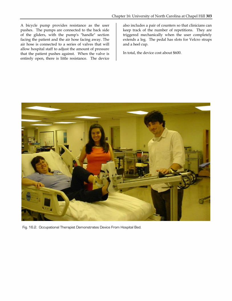
A bicycle pump provides resistance as the user pushes. The pumps are connected to the back side of the gliders, with the pump's "handle" section facing the patient and the air hose facing away. The air hose is connected to a series of valves that will allow hospital staff to adjust the amount of pressure that the patient pushes against. When the valve is entirely open, there is little resistance. The device
also includes a pair of counters so that clinicians can keep track of the number of repetitions. They are triggered mechanically when the user completely extends a leg. The pedal has slots for Velcro straps and a heel cup.
In total, the device cost about $600.
Fig. 16.2. Occupational Therapist Demonstrates Device From Hospital Bed.

304 NSF 2006 Engineering Senior Design Projects to Aid Persons with Disabilities
MOTIVATIONAL SYSTEM TO BUILD UPPER BODY STRENGTH IN CHILDREN
Designers: Erica Lee and Siroberto Scerbo Client Coordinator: Marcia Rollings
Supervising Professor: Dr. Richard Goldberg Department of Biomedical Engineering
Room 152 MacNider, CB # 7575 University of North Carolina at Chapel Hill
Chapel Hill, NC 27599
INTRODUCTION A device was developed to help babies and toddlers build upper body strength. The device is placed adjacent to a child lying on his or her stomach. It helps to motivate the child to raise his or her head or upper body. When the child raises his or her head and shoulders, the device provides a stimulus such as music, bright lights, or vibration. This encourages the child to keep lifting the head and shoulders, which builds upper body strength, a precursor to crawling.
SUMMARY OF IMPACT The client coordinator described the first time she used this device on a client: The client‟s “PT would love to see him on a wedge bearing more weight on his hands and using his hands [to build upper body strength]. He tolerates being on the floor on his tummy for short amounts of time, but does not tolerate being on the wedge. The first time we tried this device, he lifted his head and the device started playing, „Who, Who, Who let the dogs out?‟ His grin went from ear to ear. Then he continued to lift his head through the next rap song. Before we knew it, [the client] had been happily on the wedge for 15 minutes.”
TECHNICAL DESIGN To fulfill the design criteria, an infrared beam, similar to what is used in a burglary alarm system, was used. The completed device (see Fig. 16.3 and Fig. 16.4) looks like a walker with wheels. It has the infrared transmitter/detector unit and battery case mounted on the left, speakers mounted on the crossbeam and an MP3 player with its controller on the right side. The therapist can change the height of the infrared unit (Radio Shack) so that it shines a beam just above the client, who lies face down in the middle of the device. When the client pushes up, he
or she blocks the infrared beam, which acts as a switch to trigger either a switch-activated toy or the built-in MP3 player. The infrared unit is mounted to a vertical shaft and secured by a quick release collar. This allows up or down adjustment of the device, depending on the height of the child when prone or on a wedge.
The stimulus can include music or recorded sounds to motivate the child. This is accomplished with a programmable MP3 player (Rogue Robotics, Toronto) that uses an SD flash memory card to store songs. Using any computer, the teacher or parent can add different songs as well as record family members‟ voices to the SD card.
The controller interface has an LCD, volume control, stereo plug, and two switches. The first switch controls the different musical tracks and the second controls a delay. The brain of the controller, which
Fig. 16.3. Device in Use to Trigger a Battery-Operated
Toy when the Client Pushes Up.

Chapter 16: University of North Carolina at Chapel Hill 305
makes all this possible, is a Basic Stamp II microcontroller (Parallax, Rocklin CA). It processes the signal from the infrared device, manages the
switches, sends the text to the LCD, and tells the MP3 Player which song to play from the SD card.
The total cost was approximately $350.
Fig. 16.4. Finished Product Showing Custom MP3 Player, LCD Display, Speaker, IR Transmitter/Receiver, and
Reflector Tape.

306 NSF 2006 Engineering Senior Design Projects to Aid Persons with Disabilities
COMFORT READER 2K6 Designers: Oluwaseun Omofoye and Akef Rahman
Client Coordinators: Caroline Banka Supervising Professor: Dr. Richard Goldberg
Department of Biomedical Engineering Room 152 MacNider, CB # 7575
University of North Carolina at Chapel Hill Chapel Hill, NC 27599
INTRODUCTION A girl with a traumatic brain injury has difficulty isolating lines and reading small fonts. Her injury also affects her motor control and she has spastic movements. A mechanical reading aid was developed that isolates one to two lines of text and allow her to easily scroll through the page.
SUMMARY OF IMPACT The client‟s mother says, “The reading aid has made it possible for our daughter to read independently because it isolates and magnifies one line of text at a
time, and she can move to the next line of text fairly easily. Before, someone needed to hold the book and isolate the text with a piece of paper…. The reading aid is so sturdy that she can move from one line to the next with little effort.”
TECHNICAL DESCRIPTION The reading aid consists of a rotating cylinder that is mounted on a stand. A ratchet is attached to the cylinder. The client pushes on an acrylic platform, which pushes the ratchet handle and rotates the cylinder to the next line. A black piece of acrylic
Fig. 16.5. Client Using Reading Aid.

Chapter 16: University of North Carolina at Chapel Hill 307
shields the rotating cylinder so that it is not a distraction to the client. There is a rectangular window in the acrylic, which reveals one to two lines on the page at a time. A Fresnel lens is mounted to the window to magnify the text.
The cylinder consists of a PVC pipe of radius 1 3/4 inches. Two PVC caps with holes at the center are attached to the ends of the pipe. The length of the pipe and caps is about 15 inches. Copper pipe goes through the center to form an axle. The PVC pipe and exposed parts of the copper axle are painted black.
The side supports and base of the reading aid are made of Lexan, a strong and durable polymer. All of the Lexan pieces are removable so that the device can be easily assembled and disassembled for portability. The different Lexan shapes were milled and cut from a 4‟ by 2‟ sheet that is 0.5”thick. The rough edges and surface scratches of the Lexan were blowtorched for smoothness.
The client advances the text using a ratcheting mechanism. The ratchet converts motion in a linear direction to a rotation of the cylinder, and it also allows for rotation in both clockwise and counterclockwise directions. The ratchet allows the reading aid to be rotated in the direction of interest. Once there, the reading aid remains motionless while the ratchet is rotated back to its starting position. To rotate in the opposite direction, the switch on the ratchet is turned reversing the ratcheting direction. The ratchet is a standard commercial ratchet with a 12” handle. The copper axle is soldered to a standard ratchet socket and this socket snaps into the ratchet.
The total cost of this device was approximately $440.
Fig. 16.6. Comfort Reader Device with Acrylic Screen, Fresnel Lens, and Ratcheting Mechanism.

308 NSF 2006 Engineering Senior Design Projects to Aid Persons with Disabilities
EMOD: ELECTRONIC MEDICATION ORGANIZER AND DISPENSER
Designers: Benjamin Smith, Erica Lee, Siroberto Scerbo Client Coordinators: Allison Darwin OTR/L, Cindy Thompson RN, Carolina Meadows Retirement facility
Supervising Professor: Dr. Richard Goldberg Department of Biomedical Engineering
Room 152 MacNider, CB # 7575 University of North Carolina at Chapel Hill
Chapel Hill, NC 27599
INTRODUCTION EMOD (Fig. 16.7) is a custom pill dispenser designed to give people with disabilities independence when managing complicated pill schedules. It is designed to reduce the risk of incorrect dosage. The primary objectives were to create a dependable device that is easy to use, dispenses variable medication doses, reminds clients of their medication schedules, safely halves pills when necessary, and eliminates medication loading errors. The device also had to be functional when used by a person with one arm, able to withstand tremors, and require minimal strength during usage.
SUMMARY OF IMPACT The EMOD allows clients the ability to manage complicated medication schedules with little or no help. They are easily able to load their own pills using the Pill Loader, which helps prevent errors in setting up their medication schedule. Cutting pills is safe because there is no exposed blade. Once the pills are loaded and the alarms are set, the pills are dispensed at the appropriate times, with an audible reminder.
TECHNICAL DESCRIPTION Overall operation: The heart of the device is the Medtime XL motorized 28 compartment tray (made by Careousel, Sweden, and purchased from epill.com). The existing electronics were removed, and custom electronics as well as new mechanical features were added to make it accessible to people with disabilities. The device is fully automated; the user enters the time of day, and sets up to four alarms when medication is to be taken. Then, the user loads the pills using the clear acrylic loading tray, which provides full visual and motor control over which pills go into each compartment of the pill dispenser tray. Once
loaded, the dispenser is placed upside down into the mounting stand.
When an alarm goes off, EMOD automatically advances the dispenser to the next compartment, dumps the desired pills into a small cup, and sounds an audible alert. The cup is replaced by the client after every dose. Appropriate placement of the cup is aided by a marked red area beneath the pill dispenser.
Pill Dispenser: The pill dispenser has four operational modes: Loading, Set Current Time, Set Alarms, and Run. The interface for the pill dispenser consists of three buttons, an LCD, LEDs and a switch to turn off the verbal commands. The left button cycles between the pill dispenser‟s operational modes. The middle button changes the hours and the right button changes the minutes. The LCD displays the current operational mode and gives instructions to the user.
Fig. 16.7. Front View of EMOD. Pill Dispenser is on Right
with Lid Open. Pill Loader and Pill Cutter are on Top of
Dispenser, and Mounting Stand is on Left.

Chapter 16: University of North Carolina at Chapel Hill 309
For those users who have difficulty reading the LCD, the device also provides prerecorded verbal commands. The user can toggle a switch to turn those verbal commands on or off.
For loading and run modes, a DC motor advances the dispenser tray in a clockwise motion. There are tabs on the bottom of each compartment and an infrared detector and emitter detect the passing of the tabs. When the tray advances to the next tab, the system stops the motor.
The custom circuitry consists of a PIC 16F877 microcontroller (Microchip, Inc., Chandler AZ) programmed in C-language, an ISD33120 voice recorder chip (Winbond, San Jose CA), an LM386 amplifier and a MAX232 driver.
Pill Loader: A pill loading tray (Fig. 16.8) was developed to facilitate the loading process. Since the user will typically take the same medication during a certain time of day (morning, noon, evening, and bedtime), the tray was designed so that the user first loads all morning pills for the week. The upper loading tray has holes for every fourth compartment so that the user can load these pills in the appropriate places. Initially, the pills sit below the upper loading tray, but on top of the lower tray. This allows for easy
correction in case of any loading mistakes. Once the user confirms that all of the pills are placed properly, then he or she slides a lever on the lower tray to drop them simultaneously into the compartments below. They repeat this process for the noon, evening, and bedtime pills.
The upper tray loader was constructed of 0.177” thick clear acrylic. Using a laser cutter, seven large thumb-print sized holes were cut over every fourth compartment of the pill dispenser. The lower tray loader was cut out using 0.08” clear acrylic but was modified to include an extra piece as a handle. To prevent pills from falling over the outer edge, 0.177” thick white acrylic was used to create a ring barrier on the outermost edge of the top piece.
Pill Cutter: The custom Pill Cutter is designed with safety guards and a sliding loading tray that protect the user from the sharp blade. The blade guards and limited opening angle prevent the blade from being exposed. A stop bar limits the opening angle, which prevents the blade from being exposed.
The total cost of the project was $384.
Fig. 16.8. User Loading Pills into Pill Loader Trays.

310 NSF 2006 Engineering Senior Design Projects to Aid Persons with Disabilities
SWITCH RELAY Designers: Andres Afanador and Laura Malone
Client Coordinator: Kevin Caves, ME, ATP, RET, Duke University, RERC on Communication Enhancement Supervising Professor: Dr. Richard Goldberg
Department of Biomedical Engineering Room 152 MacNider, CB # 7575
University of North Carolina at Chapel Hill Chapel Hill, NC 27599
INTRODUCTION The Switch Relay was designed to give clients control over two different switch-activated devices using only one switch. Pressing and releasing the switch directly controls the first device. However, when the client presses the switch for a preset minimum duration of time, “hold time,” the device toggles its state to control a second device. An example of this is shown in Fig. 16.9, where one switch controls both a computer and a communication device. A knob allows the client to adjust the minimum pressing duration from 0.5 to eight seconds, in one-second increments to set the
“hold time”. Subsequent switch presses that are longer than the minimum duration will toggle control of the Switch Relay between the two devices. An LED readout shows which device is being controlled at a given time.
SUMMARY OF IMPACT Allowing operation of multiple devices with one switch increases the user‟s independence. The use of only one switch to operate a pair of devices minimizes confusion for the user.
Because of the adjustable “hold time,” devices with
Fig. 16.9. Switch Relay Device Attached to a PC and a Communication Device.

Chapter 16: University of North Carolina at Chapel Hill 311
different activation times can be operated; therefore, almost any switch-activated device can be controlled with the Switch Relay. The coordinator stated that "the device will enable people with limited physical ability to independently operate multiple devices."
TECHNICAL DESCRIPTION The Switch Relay circuit (Fig. 16. 10) is based on a PIC microcontroller (Microchip, Inc., Chandler AZ), which detects the activation of the user‟s switch. The PIC can determine the amount of time the switch is held, and then either change devices or continue to operate the current device. Latching SPDT relay switches (Omron G6EK-134P) were used to isolate electronically the output devices from each other and the input switch. The use of latching switches allows for reduced power consumption, because they require a pulse for activation rather
than a continuously applied voltage. Transistors (2N222A) were used to apply sufficient current to the relays.
The adjustable “hold time” is set using a potentiometer, which is read by the A/D converter of the PIC. LEDs indicate which device is under the control of the switch. An additional LED light bar indicates the length of the “hold time.”
The electronics are housed in a 3.5” x 7.0” plastic project box. Two mono 1/8” audio cables are attached to connect to the devices. A standard 1/8” mono audio jack is used as the input terminal, to which the switch is attached. The device is powered by a 9V battery with a regulator controlling the voltage applied to the circuitry.
The total cost of the device was approximately $40.
To Device A
RB0/INT
RB1
RB2
RB4
RB5
RB3/PGM
RB6/PGC
RB7/PGD
RC0/T1OSO
RC1/T1OSI
RC2/CCP1
RC3/SCK
RC4/SDI
RC5/SDO
RC6/TX
RC7/RX
VSSVSS
VDD
RA0/AN0
RA1/AN1
RA2/AN2
RA3/AN3
RA4/T0CKI
RA5/AN4
OSC1/CLKIN
OSC2/CLKOUT
/MCLR/VPP
2
3
4
5
6
7
9
10
1
33pF
4MHz
33pF
X1C1
C2
D D
R
R
R
1K
1K 8 19
U1 20
21
22
23
24
25
26
27
PIC
16F876
28
11
12
13
14
15
16
17
16To Device B
1K
1KR
R
NC
NO NC
NO
To LED Bar
To LED Bar
SW
IN
EN AUX
OUT2
4 5
3
U3C3
GNDSWS
1
1 uF
+9v
Fig. 16.10. Switch Relay Circuit Diagram.

312 NSF 2006 Engineering Senior Design Projects to Aid Persons with Disabilities
ACCESSIBLE GARDEN BED AND ADJUSTABLE HANGING BASKET
Designers: Tejan Diwanji, Michael Murray Client Coordinator: Allison Darwin, OT Carolina Meadows
Supervising Professor: Dr. Richard L. Goldberg Department of Biomedical Engineering
Room 152 MacNider, CB #7575 University of North Carolina at Chapel Hill
Chapel Hill, NC 27599
INTRODUCTION A multifunctional living community provides housing and recreational facilities for elderly people. The community offers a range from totally independent-living houses and apartments to intensive care facilities. The goal was to improve a garden area at this facility to allow for easier access for the residents. A previous raised garden bed was difficult to access for residents in wheelchairs.
The hanging planter and birdfeeder operate with a pulley and winch system, which allows for residents to adjust the height so that they can attend to these items. They can water plants, clip dead leaves or refill the birdfeeder with seeds. The garden bed and the hanging basket help the residents to engage in everyday activities to exercise, maintain mobility, and retain a sense of independence.
SUMMARY OF IMPACT The client coordinator stated, “The wheelchair accessible raised garden bed will allow residents to actively engage in gardening activities, regardless of physical ability. Prior to the construction of this bed, residents who use wheelchairs did not have an adequate way to functionally and naturally participate in gardening activities due to the inability to get close enough to a garden bed to interact with the soil and plants. We hope that this addition to our existing courtyard will enhance activities for residents and enrich overall quality of life for these older adults.”
TECHNICAL DESCRIPTION The garden bed is shown in Fig. 16.11. It is made of five sheets of ¾” x 4” x 8” pressure treated plywood supported in the corners by 2” x 2” lumber and across the top by 2” x 4” lumber. The structure is held together by 2” galvanized deck screws. It
consists of three main pieces: two boxes measuring about 17” x 33” x 35” for the bases and a third piece spanning the gap between the bases. The third piece allows for about 6” of soil to be placed on top of it. Space was allowed within the two bases for the resident to be able to pull his or her wheelchair under it. Space in this area is about 29” from side to side and roughly 27” from bottom to top.
Two drawers were built into the bed for tool storage. Within these drawers, tools are easily accessible to an individual at the garden bed. They were constructed using pressure treated plywood, 1 ¼” stainless steal screws, and two sets of drawer slides. A drawer box was connected to the base and the top piece on the inner right side for support. The drawer boxes were constructed with pressure treated plywood and 2” galvanized screws.
For the pulley system, about 24‟ of 1/8” plastic coated steel cable was used. The cable is held up by two steel pulleys, each with the capability of holding over 55 lbs. To allow for easy movement of the
Fig. 16.11. Garden Bed Showing Open Drawer that
Holds Gardening Tools.

Chapter 16: University of North Carolina at Chapel Hill 313
hanging item (Fig. 16.12) a two-way boat winch was used. The load can be raised and lowered easily and without slipping.
Construction was done in the facility‟s woodshop. One of the residents of the facility helped with construction and installation.
Total cost was about $400.
Fig. 16.12. Hanging Planter Controlled by Pulley System.

314 NSF 2006 Engineering Senior Design Projects to Aid Persons with Disabilities