chapter 17 overcurrent protection: fuses and circuit breakers
TRANSCRIPT

Chapter 17
Overcurrent Protection:Fuses and Circuit Breakers
Objectives• List and identify the types, classes, and
ratings of fuses and circuit breakers
• Describe the operation of fuses and circuit breakers
• Develop an understanding of switch sizes, ratings, and requirements
Objectives (cont'd.)• Define interrupting rating, short-circuit
currents, I2t, Ip, RMS, and current limitation
• Apply the National Electrical Code to the selection and installation of overcurrent protective devices
• Use the time-current characteristics curves and peak let-through charts
Overcurrent Protection• NEC® Article 240 states the requirements
for overcurrent protection– NEC® 240.1 (FPN): use if the current reaches a
value that will cause excessive temperature in conductors or conductor insulation
• Two types of overcurrent protective devices are commonly used: – Fuses and circuit breakers
Overcurrent Protection (cont'd.)• Underwriters Laboratories, Inc. (UL) and
National Electrical Manufacturers Association (NEMA) establish standards for ratings, types, classifications, and testing procedures for fuses and circuit breakers
Disconnect Switches• Fused switches are available in ratings of
several amperes in both 250 and 600 volts– Used with copper conductors unless marked to
indicate suitability for use with aluminum– Rating, unless otherwise marked, is based on:
• 140°F (60°C) wire (14 AWG through 1 AWG) and 167°F (75°C) for wires 1/0 AWG and larger
– May be equipped with ground-fault sensing and labels that indicate their intended use
Disconnect Switches (cont'd.)• Accessibility of overcurrent devices
– Occupants of must have access to overcurrent devices for their circuits, NEC® 240.24(B)
• How high should disconnect switches be mounted?– NEC® 240.24(A) requires that overcurrent
devices be readily accessible– Same rule applies to a circuit breaker
Fuses and Circuit Breakers• Voltage rating
– Equal to or greater than the voltage of the circuit in which they are to be used
• Continuous current rating– Amperes that the device can continuously carry– Rating is usually based on the ampacity of
circuit conductors
Fuses and Circuit Breakers (cont'd.)
• Protection of conductors– When overcurrent device is rated at 800
amperes or less• The Code permits the use of next higher standard
ampere-rated fuse or circuit breaker
Fuses and Circuit Breakers (cont'd.)
– When overcurrent device is rated above 800-ampere
• Conductor ampacity must be equal to or greater than the rating of the fuse or circuit breaker
• Interrupting rating– Highest current where a device is intended to
interrupt under standard test conditions
Fuses and Circuit Breakers (cont'd.)
• Short-circuit current rating– Ability to withstand fault current equal to or less
than the short-circuit rating for the length of time it takes the overcurrent device to react
• Speed of response– Time required for a fuse to open varies
inversely with current that flows through fuse– Circuit breaker also has this characteristic
Types of Fuses• Dual-element, time-delay fuse
– Provides a time delay in low-overload range to eliminate unnecessary opening of the circuit because of harmless overloads
• Using fuses for motor overload protection– Sizing dual-element fuses slightly larger than the
overload relay provides backup protection– If overload relays fail to operate, dual-element
fuses will provide backup overload protection
Types of Fuses (cont'd.)• Applying fuses and breakers on motor
circuits– High starting currents of motors can cause
nuisance opening of fuses and nuisance tripping of circuit breakers
– Check time-current curves of fuses and breakers to make sure that they will handle the momentary motor starting inrush currents without nuisance opening or tripping
Types of Fuses (cont'd.)• Using fuses for motor branch-circuit, short-
circuit, and ground-fault protection– NEC® Table 430.52: maximum size permitted for
dual-element fuses is based on a maximum of 175 percent of full-load current of the motor
• Dual-element, time-delay, current-limiting fuses– Can handle currents five times their ampere
rating for at least 10 seconds
Types of Fuses (cont'd.)
• Fast-acting, current-limiting fuses (nontime-delay)– Extremely fast response in both low-overload
and short-circuit ranges– Has the lowest energy let-through values– Provides better protection to mains, feeders
and subfeeders, circuit breakers, bus duct, switchboards, and other circuit components
Types of Fuses (cont'd.)• Types of cartridge fuses
– According to the Code, all cartridge fuses must be marked to show:
• Ampere rating• Voltage rating• Interrupting rating when greater than 10,000
amperes• Current-limiting type, if applicable• Trade name or name of manufacturer
Types of Fuses (cont'd.)• Plug fuses
– Requirements in NEC® Article 240, Part V– Opening characteristics available in three types:
• Standard link type does not have much time delay• Loaded link type has a metal bead element that gives
it time delay to hold motor inrush starting currents• Dual-element, time-delay has a spring-loaded short-
circuit element plus an overload element connected in series with short-circuit element
Testing Fuses• OSHA: electrical equipment must not be
worked on when it is energized
• When power is turned on:– Exercise extreme caution when checking fuses– Using a voltmeter, first step is to set the scale
to its highest voltage setting and then change to a lower scale after you are within the range of the voltmeter
Testing Fuses (cont'd.)– Reading from line-to-load side of a good fuse
should show zero to small voltage
• When power is turned off:– Remove fuse from switch, then use an
ohmmeter to take a resistance reading– Good fuse: zero or a very minimal resistance;
open (blown) fuse will show a high reading
Testing Fuses (cont'd.)• Cable limiters
– Used where parallel cables are used on service entrances and feeders
– Devices that can isolate a faulted cable rather than having the fault open the entire phase
– Selected on the basis of conductor size– Are available for cable-to-cable or cable-to-bus
installation for either aluminum or copper hot phase conductors
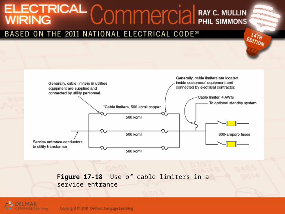
Figure 17-18 Use of cable limiters in a service entrance
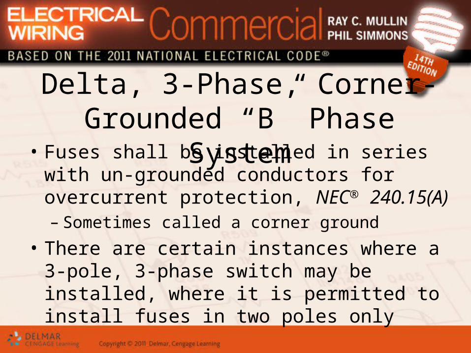
Delta, 3-Phase, Corner-Grounded “B” Phase System
• Fuses shall be installed in series with un-grounded conductors for overcurrent protection, NEC® 240.15(A)– Sometimes called a corner ground
• There are certain instances where a 3-pole, 3-phase switch may be installed, where it is permitted to install fuses in two poles only
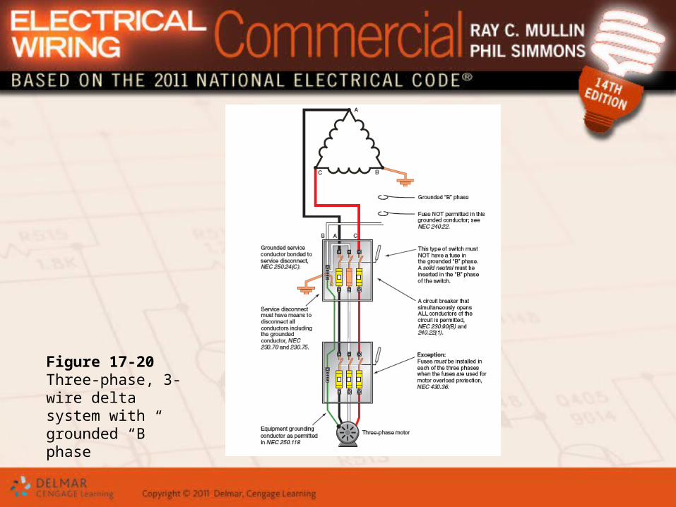
Figure 17-20 Three-phase, 3-wire delta system with grounded “B” phase
Delta, 3-Phase, Corner-Grounded “B” Phase System (cont'd.)
• Solid neutrals– Made of copper bar that has exactly the same
dimensions as a fuse for a given ampere rating and voltage rating
– Generally used in retrofit situations
Time-Current Characteristic Curves and Peak Let-Through
Charts• Fuse manufacturers furnish information for:
– Time-current characteristic curves, including total clearing and minimum melting curves
– Peak let-through charts• Time-current characteristic curves can be used to
answer questions about fuse capabilities
Peak Let-Through Charts (cont'd.)
• The use of peak let-through charts– Properly matches short-circuit current rating of
electrical equipment with let-through current values of overcurrent protective devices
• Peak let-through charts give a good indication of current-limiting effects of a current-limiting fuse or circuit breaker under “bolted fault” conditions
Circuit Breakers• NEC® Article 100 definition
– Device designed to open and close a circuit by nonautomatic means and to open the circuit automatically on a predetermined overcurrent
• Types of circuit breakers:– Molded-case circuit breakers– Power circuit breakers– Insulated-case circuit breakers
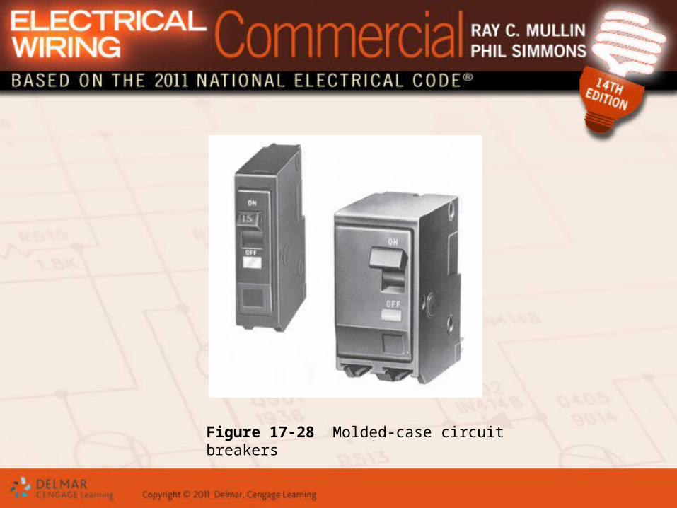
Figure 17-28 Molded-case circuit breakers
Circuit Breakers (cont'd.)• NEC® 240.80 through 240.86 state the basic
requirements for circuit breakers• Thermal-magnetic circuit breakers
– Contain a bimetallic element that, on continuous overload, moves until it unlatches the inner tripping mechanism of the breaker
– Time required for the breaker to open the circuit depends upon the fault current and mechanical condition of circuit breaker
Circuit Breakers (cont'd.)
• Ambient-compensated circuit breakers– Some circuit breakers are ambient
(surrounding temperature) compensated– If installing thermal circuit breakers in
extremely hot or extremely cold temperatures, consult manufacturers’ literature
– Ambient factors can affect proper operation of a circuit breaker, such as dust, fumes, etc.
Circuit Breakers (cont'd.)
• Common misapplication– Common violation of NEC® 110.9 and 110.10:
• Installation of a main circuit breaker that has a high interrupting rating while making the assumption that branch-circuit breakers are protected adequately against short circuit
– Standard molded case circuit breakers with high interrupting ratings cannot protect standard end-use equipment having lower interrupting rating
Series-Rated Applications• Series-rated equipment
– Main overcurrent device and branch-circuit overcurrent devices are connected in series
• Series-rated systems– Less costly than fully-rated systems– Available fault current does not exceed
interrupting rating of the line-side overcurrent device but does exceed interrupting rating of the load-side overcurrent device
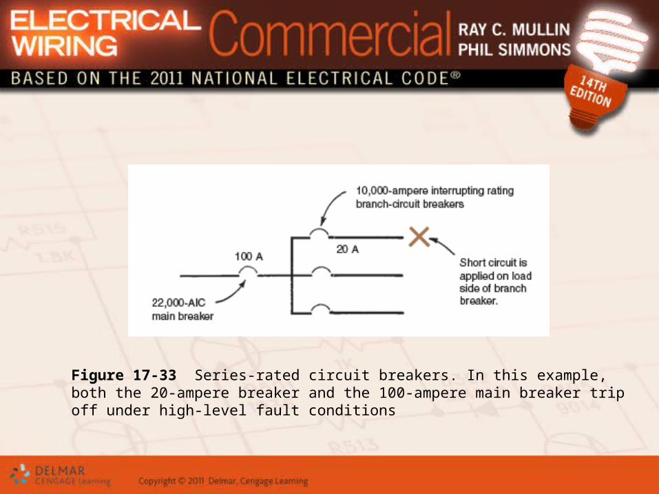
Figure 17-33 Series-rated circuit breakers. In this example, both the 20-ampere breaker and the 100-ampere main breaker trip off under high-level fault conditions
Series-Rated Applications (cont'd.)
• Where high available fault currents indicate the need for high interrupting breakers or fuses, fully rated system is generally used
• Another less costly way to safely match main circuit breaker or main fuses ahead of branch-circuit breakers is to use listed series-rated equipment
Series-Rated Systems Where Electric Motors are Connected
• NEC® 240.86(C) sets forth two requirements– Do not connect electric motors between load
side of higher rated overcurrent device and line side of lower rated overcurrent device
– Sum of connected motor full-load currents shall not exceed one percent of the interrupting rating of lower rated circuit breaker
Current-Limiting Breakers• Current-limiting circuit breaker limits the let-
through energy (I2t) to something less than the I2t of a one-half cycle symmetrical wave
• When installing circuit breakers, it is important to ensure that:– Circuit breakers have the proper rating– All circuit components can withstand the let-
through current of the breaker
Cost Considerations• There are a number of different types of
circuit breakers to choose from
• Selection of the type to use depends upon a number of factors, including interrupting rating, selectivity, space, and cost
Motor Circuits• NEC® Table 430.52
– Shows that maximum setting of a conventional inverse-time circuit breaker must not exceed 250 percent of full-load current of the motor
– For instantaneous-trip circuit breaker, maximum setting is 800 percent of motors’ full-load current
• Design B motors, the maximum setting is 1100 percent
Motor Circuits (cont'd.)• If an “engineering evaluation” can
demonstrate the need to exceed percentages shown in NEC® Table 430.52, then:– 800 percent setting may be increased to a
maximum of 1300 percent– 1100 percent setting may be increased to a
maximum of 1700 percent
Heating, Air-Conditioning, and Refrigeration Overcurrent
Protection• Check the nameplate carefully—and do
what it says– Nameplate on HVAC equipment might indicate
“maximum size fuse,” “maximum size fuse or circuit breaker,” or “maximum size fuse or HACR circuit breaker”
Summary• NEC® Article 240 sets the requirements for
overcurrent protection
• Two types of overcurrent protective devices commonly used: fuses and circuit breakers
• Factors that must be considered when selecting proper fuses and circuit breakers:– Voltage rating, continuous current rating,
interrupting rating, and speed of response