chapter 18 direct current circuits. clicker question 1 a wire has resistance r. a second wire has...
TRANSCRIPT

Chapter 18
Direct Current Circuits

Clicker question 1A wire has resistance R. A second wire has twice the length, twice the diameter, and twice the resistivity of the first wire. What is its resistance?
a) 8R b) R c) R/4 d) not enough information

Clicker question 2When the voltage across a nonohmic resistor is doubled, the current through it triples. What happens to the power delivered to this resistor? a. This cannot be answered with the information given.b. The power decreases to 2/3 of the original
amount.c. The power increases to 1.5 times the original
amount.d. The power increases to 6 times the original
amount.

Sources of emf The source that maintains the current in
a closed circuit is called a source of emf Any devices that increase the potential
energy of charges circulating in circuits are sources of emf
Examples include batteries and generators SI units are Volts
The emf is the work done per unit charge

emf and Internal Resistance A real battery has
some internal resistance
Therefore, the terminal voltage is not equal to the emf

More About Internal Resistance
The schematic shows the internal resistance, r
The terminal voltage is ΔV = Vb-Va
ΔV = ε – Ir For the entire circuit,
ε = IR + Ir

Internal Resistance and emf, cont ε is equal to the terminal voltage
when the current is zero Also called the open-circuit voltage
R is called the load resistance The current depends on both the
resistance external to the battery and the internal resistance

Internal Resistance and emf, final When R >> r, r can be ignored
Generally assumed in problems Power relationship
I e = I2 R + I2 r When R >> r, most of the power delivered by the battery is transferred to the load resistor

Resistors in Series When two or more resistors are
connected end-to-end, they are said to be in series
The current is the same in all resistors because any charge that flows through one resistor flows through the other
The sum of the potential differences across the resistors is equal to the total potential difference across the combination

Resistors in Series, cont Potentials add
ΔV = IR1 + IR2 = I (R1+R2)
Consequence of Conservation of Energy
The equivalent resistance has the effect on the circuit as the original combination of resistors

Equivalent Resistance – Series Req = R1 + R2 + R3 + … The equivalent resistance of a
series combination of resistors is the algebraic sum of the individual resistances and is always greater than any of the individual resistors

Equivalent Resistance – Series: An Example
Four resistors are replaced with their equivalent resistance

Resistors in Parallel The potential difference across each
resistor is the same because each is connected directly across the battery terminals
The current, I, that enters a point must be equal to the total current leaving that point I = I1 + I2 The currents are generally not the same Consequence of Conservation of Charge

Equivalent Resistance – Parallel, Example
Equivalent resistance replaces the two original resistances
Household circuits are wired so the electrical devices are connected in parallel
Circuit breakers may be used in series with other circuit elements for safety purposes

Equivalent Resistance – Parallel
Equivalent Resistance
The inverse of the equivalent resistance of two or more resistors connected in parallel is the algebraic sum of the inverses of the individual resistance
The equivalent is always less than the smallest resistor in the group
321eq R
1
R
1
R
1
R
1

Problem-Solving Strategy, 1 Combine all resistors in series
They carry the same current The potential differences across them
are not the same The resistors add directly to give the
equivalent resistance of the series combination: Req = R1 + R2 + …
Draw the simplified circuit diagram

Problem-Solving Strategy, 2
Combine all resistors in parallel The potential differences across them are
the same The currents through them are not the same The equivalent resistance of a parallel
combination is found through reciprocal addition:
Draw the simplified circuit diagram
321eq R
1
R
1
R
1
R
1

Problem-Solving Strategy, 3 A complicated circuit consisting of
several resistors and batteries can often be reduced to a simple circuit with only one resistor Replace any resistors in series or in parallel
using steps 1 or 2. Sketch the new circuit after these changes
have been made Continue to replace any series or parallel
combinations Continue until one equivalent resistance is
found

Problem-Solving Strategy, 4 If the current in or the potential
difference across a resistor in the complicated circuit is to be identified, start with the final circuit found in step 3 and gradually work back through the circuits Use ΔV = I R and the procedures in
steps 1 and 2

Example Complex circuit
reduction Combine the
resistors in series and parallel
Redraw the circuit with the equivalents of each set
Combine the resulting resistors in series
Determine the final equivalent resistance
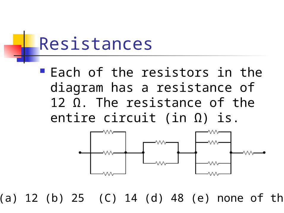
Resistances Each of the resistors in the
diagram has a resistance of 12 Ω. The resistance of the entire circuit (in Ω) is.
(a) 12 (b) 25 (C) 14 (d) 48 (e) none of these

Figure shows five 5.00 Ω resistors. Find the equivalent resistance between points (a) F and H and (b) F and G. (Hint: For each pair of points, imagine that a battery is connected across the pair.)
a : 2.5 Ω b: 3.13 Ω

Figure shows five 5.00 Ω resistors. Find the equivalent resistance between points (a) F and H and (b) F and G. (Hint: For each pair of points, imagine that a battery is connected across the pair.)
Between F and H = R/2 = 2.5ΩBetween F and G = 5R/8 = 3.1Ω

Circuits, Junctions Charge can not
be created, nor destroyed
Total Current in = Total current out
i = 8A
i
What is i and j?