chapter 18 ethanol distillation: the fundamentals · lower boiling point, ... normally...
TRANSCRIPT
Ethanol distillation: the fundamentals 269
Chapter 18
Ethanol distillation: the fundamentals
R. Katzen, P.W. Madson and G.D. Moon, JrKATZEN International, Inc., Cincinnati, Ohio, USA
Fundamentals of a distilling system
Certain fundamental principles are common toall distilling systems. Modern distillation systemsare multi-stage, continuous, countercurrent,vapor-liquid contacting systems that operatewithin the physical laws that state that differentmaterials boil at different temperatures.
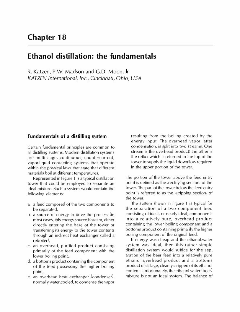
Represented in Figure 1 is a typical distillationtower that could be employed to separate anideal mixture. Such a system would contain thefollowing elements:
a. a feed composed of the two components tobe separated,
b. a source of energy to drive the process (inmost cases, this energy source is steam, eitherdirectly entering the base of the tower ortransferring its energy to the tower contentsthrough an indirect heat exchanger called areboiler),
c. an overhead, purified product consistingprimarily of the feed component with thelower boiling point,
d. a bottoms product containing the componentof the feed possessing the higher boilingpoint,
e. an overhead heat exchanger (condenser),normally water-cooled, to condense the vapor
resulting from the boiling created by theenergy input. The overhead vapor, aftercondensation, is split into two streams. Onestream is the overhead product; the other isthe reflux which is returned to the top of thetower to supply the liquid downflow requiredin the upper portion of the tower.
The portion of the tower above the feed entrypoint is defined as the �rectifying section� of thetower. The part of the tower below the feed entrypoint is referred to as the �stripping section� ofthe tower.
The system shown in Figure 1 is typical forthe separation of a two component feedconsisting of ideal, or nearly ideal, componentsinto a relatively pure, overhead productcontaining the lower boiling component and abottoms product containing primarily the higherboiling component of the original feed.
If energy was cheap and the ethanol-watersystem was ideal, then this rather simpledistillation system would suffice for the sep-aration of the beer feed into a relatively pureethanol overhead product and a bottomsproduct of stillage, cleanly stripped of its ethanolcontent. Unfortunately, the ethanol-water (beer)mixture is not an ideal system. The balance of
270 R. Katzen, P.W. Madson and G.D. Moon, Jr.
this chapter will be devoted to a description ofthe modifications required of the simpledistillation system in order to make it effectivefor the separation of a very pure ethanol product,essentially free of its water content.
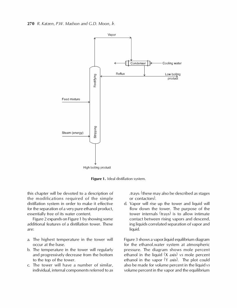
Figure 2 expands on Figure 1 by showing someadditional features of a distillation tower. Theseare:
a. The highest temperature in the tower willoccur at the base.
b. The temperature in the tower will regularlyand progressively decrease from the bottomto the top of the tower.
c. The tower will have a number of similar,individual, internal components referred to as
�trays� (these may also be described as stagesor contactors).
d. Vapor will rise up the tower and liquid willflow down the tower. The purpose of thetower internals (trays) is to allow intimatecontact between rising vapors and descend-ing liquids correlated separation of vapor andliquid.
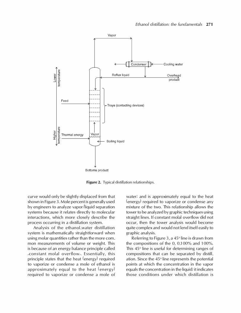
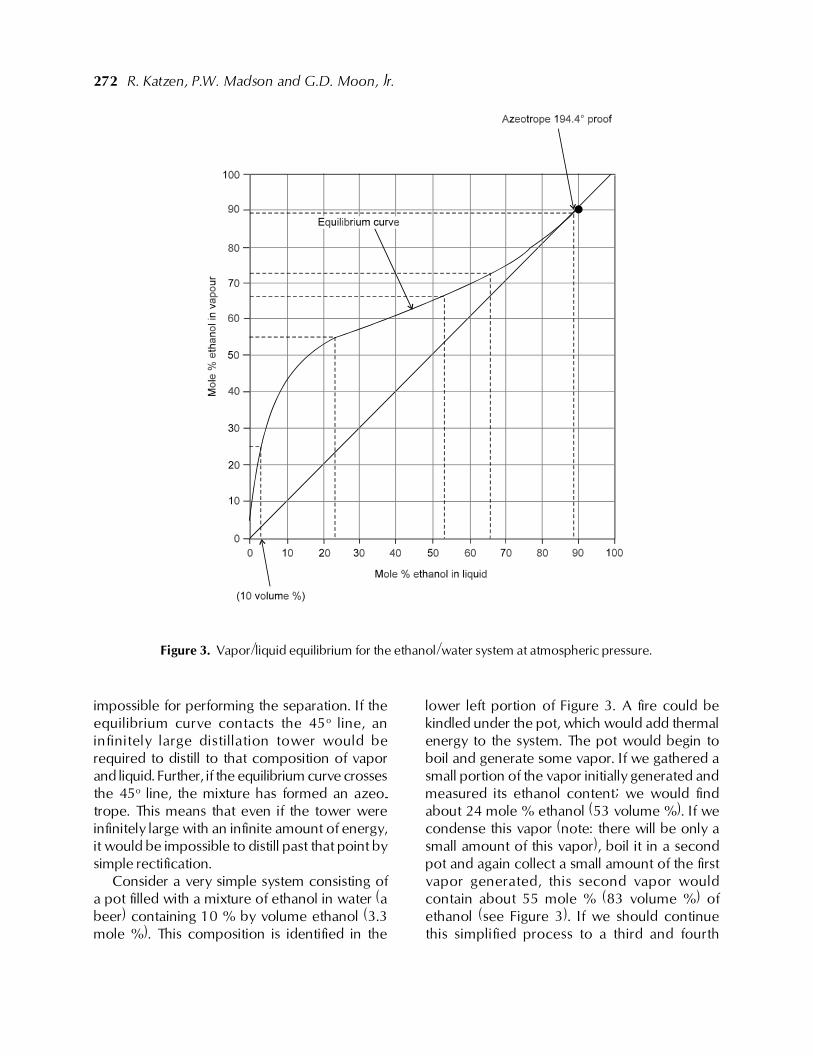
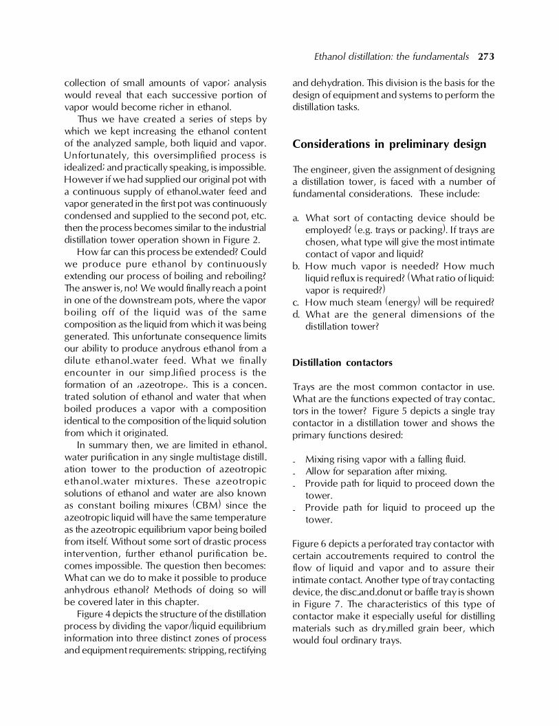
Figure 3 shows a vapor-liquid equilibrium diagramfor the ethanol-water system at atmosphericpressure. The diagram shows mole percentethanol in the liquid (X axis) vs mole percentethanol in the vapor (Y axis). The plot couldalso be made for volume percent in the liquid vsvolume percent in the vapor and the equilibrium
Figure 1. Ideal distillation system.
Ethanol distillation: the fundamentals 271
curve would only be slightly displaced from thatshown in Figure 3. Mole percent is generally usedby engineers to analyze vapor/liquid separationsystems because it relates directly to molecularinteractions, which more closely describe theprocess occurring in a distillation system.
Analysis of the ethanol-water distillationsystem is mathematically straightforward whenusing molar quantities rather than the more com-mon measurements of volume or weight. Thisis because of an energy balance principle called�constant molal overflow�. Essentially, thisprinciple states that the heat (energy) requiredto vaporize or condense a mole of ethanol isapproximately equal to the heat (energy)required to vaporize or condense a mole of
water; and is approximately equal to the heat(energy) required to vaporize or condense anymixture of the two. This relationship allows thetower to be analyzed by graphic techniques usingstraight lines. If constant molal overflow did notoccur, then the tower analysis would becomequite complex and would not lend itself easily tographic analysis.
Referring to Figure 3, a 45o line is drawn fromthe compositions of the 0, 0-100% and 100%.This 45o line is useful for determining ranges ofcompositions that can be separated by distill-ation. Since the 45o line represents the potentialpoints at which the concentration in the vaporequals the concentration in the liquid; it indicatesthose conditions under which distillation is
Figure 2. Typical distillation relationships.
272 R. Katzen, P.W. Madson and G.D. Moon, Jr.
impossible for performing the separation. If theequilibrium curve contacts the 45o line, aninfinitely large distillation tower would berequired to distill to that composition of vaporand liquid. Further, if the equilibrium curve crossesthe 45o line, the mixture has formed an azeo-trope. This means that even if the tower wereinfinitely large with an infinite amount of energy,it would be impossible to distill past that point bysimple rectification.
Consider a very simple system consisting ofa pot filled with a mixture of ethanol in water (abeer) containing 10 % by volume ethanol (3.3mole %). This composition is identified in the
lower left portion of Figure 3. A fire could bekindled under the pot, which would add thermalenergy to the system. The pot would begin toboil and generate some vapor. If we gathered asmall portion of the vapor initially generated andmeasured its ethanol content; we would findabout 24 mole % ethanol (53 volume %). If wecondense this vapor (note: there will be only asmall amount of this vapor), boil it in a secondpot and again collect a small amount of the firstvapor generated, this second vapor wouldcontain about 55 mole % (83 volume %) ofethanol (see Figure 3). If we should continuethis simplified process to a third and fourth
Figure 3. Vapor/liquid equilibrium for the ethanol/water system at atmospheric pressure.
Ethanol distillation: the fundamentals 273
collection of small amounts of vapor; analysiswould reveal that each successive portion ofvapor would become richer in ethanol.
Thus we have created a series of steps bywhich we kept increasing the ethanol contentof the analyzed sample, both liquid and vapor.Unfortunately, this oversimplified process isidealized; and practically speaking, is impossible.However if we had supplied our original pot witha continuous supply of ethanol-water feed andvapor generated in the first pot was continuouslycondensed and supplied to the second pot, etc.then the process becomes similar to the industrialdistillation tower operation shown in Figure 2.
How far can this process be extended? Couldwe produce pure ethanol by continuouslyextending our process of boiling and reboiling?The answer is, no! We would finally reach a pointin one of the downstream pots, where the vaporboiling off of the liquid was of the samecomposition as the liquid from which it was beinggenerated. This unfortunate consequence limitsour ability to produce anydrous ethanol from adilute ethanol-water feed. What we finallyencounter in our simp-lified process is theformation of an �azeotrope�. This is a concen-trated solution of ethanol and water that whenboiled produces a vapor with a compositionidentical to the composition of the liquid solutionfrom which it originated.
In summary then, we are limited in ethanol-water purification in any single multistage distill-ation tower to the production of azeotropicethanol-water mixtures. These azeotropicsolutions of ethanol and water are also knownas constant boiling mixures (CBM) since theazeotropic liquid will have the same temperatureas the azeotropic equilibrium vapor being boiledfrom itself. Without some sort of drastic processintervention, further ethanol purification be-comes impossible. The question then becomes:What can we do to make it possible to produceanhydrous ethanol? Methods of doing so willbe covered later in this chapter.
Figure 4 depicts the structure of the distillationprocess by dividing the vapor/liquid equilibriuminformation into three distinct zones of processand equipment requirements: stripping, rectifying
and dehydration. This division is the basis for thedesign of equipment and systems to perform thedistillation tasks.
Considerations in preliminary design
The engineer, given the assignment of designinga distillation tower, is faced with a number offundamental considerations. These include:
a. What sort of contacting device should beemployed? (e.g. trays or packing). If trays arechosen, what type will give the most intimatecontact of vapor and liquid?
b. How much vapor is needed? How muchliquid reflux is required? (What ratio of liquid:vapor is required?)
c. How much steam (energy) will be required?d. What are the general dimensions of the
distillation tower?
Distillation contactors
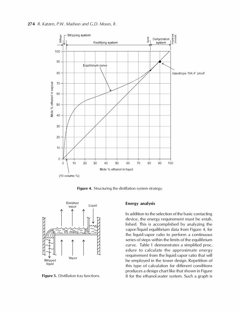
Trays are the most common contactor in use.What are the functions expected of tray contac-tors in the tower? Figure 5 depicts a single traycontactor in a distillation tower and shows theprimary functions desired:
- Mixing rising vapor with a falling fluid.- Allow for separation after mixing.- Provide path for liquid to proceed down the
tower.- Provide path for liquid to proceed up the
tower.
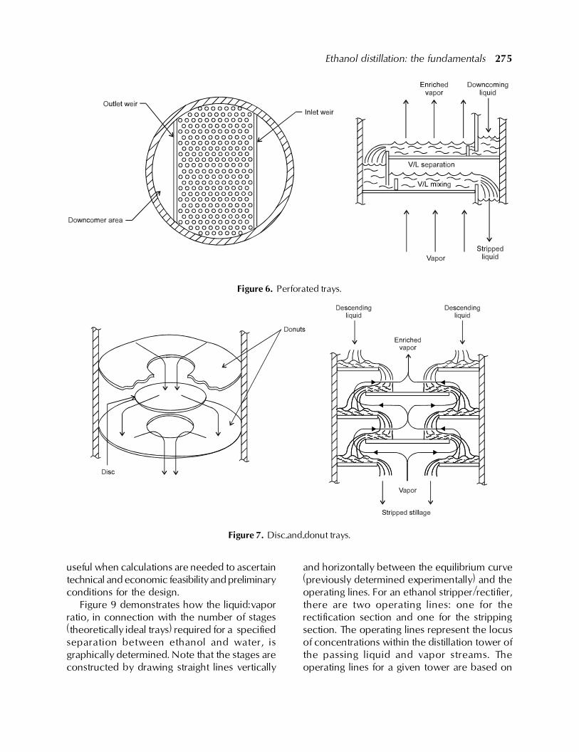
Figure 6 depicts a perforated tray contactor withcertain accoutrements required to control theflow of liquid and vapor and to assure theirintimate contact. Another type of tray contactingdevice, the disc-and-donut or baffle tray is shownin Figure 7. The characteristics of this type ofcontactor make it especially useful for distillingmaterials such as dry-milled grain beer, whichwould foul ordinary trays.
274 R. Katzen, P.W. Madson and G.D. Moon, Jr.
Energy analysis
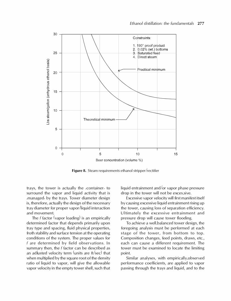
In addition to the selection of the basic contactingdevice, the energy requirement must be estab-lished. This is accomplished by analyzing thevapor/liquid equilibrium data from Figure 4, forthe liquid:vapor ratio to perform a continuousseries of steps within the limits of the equilibriumcurve. Table 1 demonstrates a simplified proc-edure to calculate the approximate energyrequirement from the liquid:vapor ratio that willbe employed in the tower design. Repetition ofthis type of calculation for different conditionsproduces a design chart like that shown in Figure8 for the ethanol-water system. Such a graph is
Figure 4. Structuring the distillation system strategy.
Figure 5. Distillation tray functions.
Ethanol distillation: the fundamentals 275
Figure 6. Perforated trays.
Figure 7. Disc-and-donut trays.
and horizontally between the equilibrium curve(previously determined experimentally) and theoperating lines. For an ethanol stripper/rectifier,there are two operating lines: one for therectification section and one for the strippingsection. The operating lines represent the locusof concentrations within the distillation tower ofthe passing liquid and vapor streams. Theoperating lines for a given tower are based on
useful when calculations are needed to ascertaintechnical and economic feasibility and preliminaryconditions for the design.
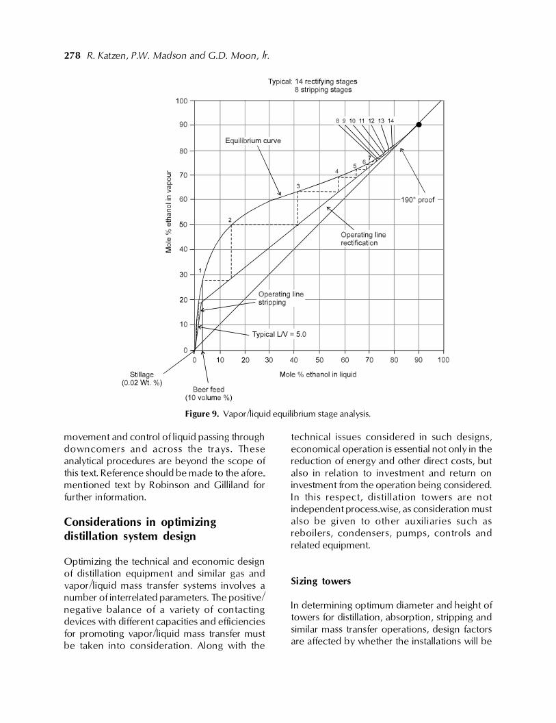
Figure 9 demonstrates how the liquid:vaporratio, in connection with the number of stages(theoretically ideal trays) required for a specifiedseparation between ethanol and water, isgraphically determined. Note that the stages areconstructed by drawing straight lines vertically
276 R. Katzen, P.W. Madson and G.D. Moon, Jr.
the energy input, as calculated and representedin Figure 8. Because of the principle of constantmolal overflow, the operating lines can berepresented as straight lines. If constant molaloverflow was not valid for the ethanol/waterdistillation, then these lines would be curved torepresent the changing ratio of liquid flow tovapor flow (in molar quantities) throughout thetower. The slope of the operating line (the ratioof liquid flow to vapor flow) is also called theinternal reflux ratio. If the energy input to a toweris increased while the beer flow remainsconstant, the operating lines will move towardthe 45o line, thus requiring fewer stages toconduct the distillation. Likewise if the energyinput is reduced (lowering the internal refluxratio), the operating lines will move toward theequilibrium curve, reducing the degree of separ-ation achievable in each stage and thereforerequiring more stages to conduct the distillation.
The calculations underlying the preparationof Figure 9 go beyond the scope and intent ofthis text, but have been included for continuity.The dashed lines represent the graphical solutionto the design calculations for the number oftheoretical stages required to accomplish adesired degree of separation of the feedcomponents. Figure 9 is referred to as a McCabe-Thiele diagram. For further pursuit of this subject,refer to the classical distillation textbook byRobinson and Gilliland (1950).
Tower sizing
The goal of the design effort is to establish thesize of the distillation tower required. Table 2shows the basic procedure to determine thediameter required for the given distillation tower.Since all of the distillation �work� is done by the
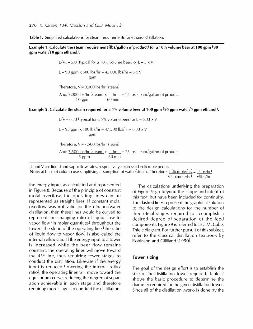
Table 1. Simplified calculations for steam requirements for ethanol distillation.
Example 1. Calculate the steam requirement (lbs/gallon of product) for a 10% volume beer at 100 gpm (90gpm water/10 gpm ethanol).
L/V* = 5.0 (typical for a 10% volume beer) or L = 5 x V
L = 90 gpm x 500 lbs/hr = 45,000 lbs/hr = 5 x Vgpm
Therefore, V = 9,000 lbs/hr (steam)
And: 9,000 lbs/hr (steam) x hr = 15 lbs steam/gallon of product 10 gpm 60 min
Example 2. Calculate the steam required for a 5% volume beer at 100 gpm (95 gpm water/5 gpm ethanol).
L/V = 6.33 (typical for a 5% volume beer) or L = 6.33 x V
L = 95 gpm x 500 lbs/hr = 47,500 lbs/hr = 6.33 x Vgpm
Therefore, V = 7,500 lbs/hr (steam)
And: 7,500 lbs/hr (steam) x hr = 25 lbs steam/gallon of product 5 gpm 60 min
*L and V are liquid and vapor flow rates, respectively, expressed in lb-mole per hr. Note: at base of column use simplifying assumption of water/steam. Therefore: L (lb-mole/hr) = L (lbs/hr)
V (lb-mole/hr) V(lbs/hr)
Ethanol distillation: the fundamentals 277
trays, the tower is actually the �container� tosurround the vapor and liquid activity that is�managed� by the trays. Tower diameter designis, therefore, actually the design of the necessarytray diameter for proper vapor/liquid interactionand movement.
The f factor (vapor loading) is an empiricallydetermined factor that depends primarily upontray type and spacing, fluid physical properties,froth stability and surface tension at the operatingconditions of the system. The proper values forf are determined by field observations. Insummary then, the f factor can be described asan adjusted velocity term (units are ft/sec) thatwhen multiplied by the square root of the densityratio of liquid to vapor, will give the allowablevapor velocity in the empty tower shell, such that
liquid entrainment and/or vapor phase pressuredrop in the tower will not be exces-sive.
Excessive vapor velocity will first manifest itselfby causing excessive liquid entrainment rising upthe tower, causing loss of separation efficiency.Ultimately the excessive entrainment andpressure drop will cause tower flooding.
To achieve a well-balanced tower design, theforegoing analysis must be performed at eachstage of the tower, from bottom to top.Composition changes, feed points, draws, etc.,each can cause a different requirement. Thetower must be examined to locate the limitingpoint.
Similar analyses, with empirically-observedperformance coefficients, are applied to vaporpassing through the trays and liquid, and to the
Figure 8. Steam requirements ethanol stripper/rectifier
278 R. Katzen, P.W. Madson and G.D. Moon, Jr.
movement and control of liquid passing throughdowncomers and across the trays. Theseanalytical procedures are beyond the scope ofthis text. Reference should be made to the afore-mentioned text by Robinson and Gilliland forfurther information.
Considerations in optimizingdistillation system design
Optimizing the technical and economic designof distillation equipment and similar gas andvapor/liquid mass transfer systems involves anumber of interrelated parameters. The positive/negative balance of a variety of contactingdevices with different capacities and efficienciesfor promoting vapor/liquid mass transfer mustbe taken into consideration. Along with the
technical issues considered in such designs,economical operation is essential not only in thereduction of energy and other direct costs, butalso in relation to investment and return oninvestment from the operation being considered.In this respect, distillation towers are notindependent process-wise, as consideration mustalso be given to other auxiliaries such asreboilers, condensers, pumps, controls andrelated equipment.
Sizing towers
In determining optimum diameter and height oftowers for distillation, absorption, stripping andsimilar mass transfer operations, design factorsare affected by whether the installations will be
Figure 9. Vapor/liquid equilibrium stage analysis.
Ethanol distillation: the fundamentals 279
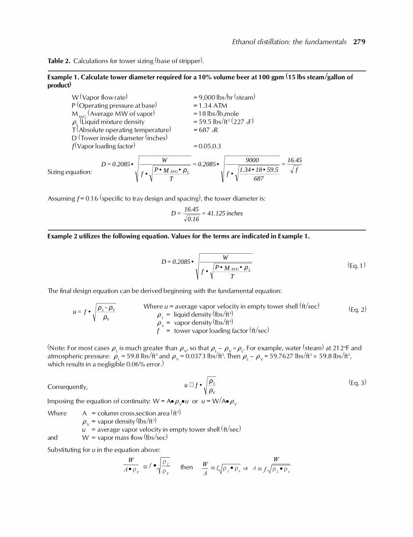
Table 2. Calculations for tower sizing (base of stripper).
Example 1. Calculate tower diameter required for a 10% volume beer at 100 gpm (15 lbs steam/gallon ofproduct)
W (Vapor flow rate) = 9,000 lbs/hr (steam)P (Operating pressure at base) = 1.34 ATMMAVG (Average MW of vapor) = 18 lbs/lb-moleDL (Liquid mixture density = 59.5 lbs/ft3 (227 °F)T (Absolute operating temperature) = 687 °RD (Tower inside diameter (inches)f (Vapor loading factor) = 0.05-0.3
Sizing equation: f
16.45=
68759.5181.34
f
90000.2085=
TMP
f
W0.2085=D
LAVG ••••
••••
ρ
Assuming f = 0.16 (specific to tray design and spacing), the tower diameter is:
inches41.125=0.16
16.45=D
Example 2 utilizes the following equation. Values for the terms are indicated in Example 1.
TMP
f
W0.2085=D
LAVG ρ••••
The final design equation can be derived beginning with the fundamental equation:
ρρρ
V
VL -f=u •
(Note: For most cases DL is much greater than DV, so that DL � DV �DL. For example, water (steam) at 212oF andatmospheric pressure: DL = 59.8 lbs/ft3 and DV = 0.0373 lbs/ft3. Then DL � DV = 59.7627 lbs/ft3 � 59.8 lbs/ft3,which results in a negligible 0.06% error.)
Consequently, ρρ
V
Lfu •≅
Imposing the equation of continuity: W = A!DV!u or u = W/A!DV
Where A = column cross-section area (ft2)DV = vapor density (lbs/ft3)u = average vapor velocity in empty tower shell (ft/sec)
and W = vapor mass flow (lbs/sec)
Substituting for u in the equation above:
then
(Eq. 1)
(Eq. 2)
(Eq. 3)
Where u = average vapor velocity in empty tower shell (ft/sec)D
L= liquid density (lbs/ft3)
DV
= vapor density (lbs/ft3)f = tower vapor loading factor (ft/sec)
280 R. Katzen, P.W. Madson and G.D. Moon, Jr.
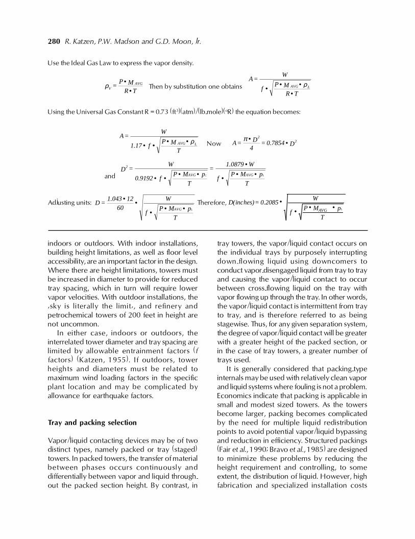
Use the Ideal Gas Law to express the vapor density.
TRMP
= AVGV •
•ρ Then by substitution one obtains TR
MPf
W=A
LAVG
•••• ρ
Using the Universal Gas Constant R = 0.73 (ft3)(atm)/(lb-mole)(oR) the equation becomes:
TMP
f1.17
W=A
LAVG ρ•••• Now D0.7854=4D=A 2
2
••π
and T
pMPf
W1.0879=
T
pMPf0.9192
W=D
LAVGAVG
2
•••
••••• L
Adjusting units:
T
pMPf
W
60
121.043=D
LAVG•••••
Therefore,
T
pMAVGPf
W0.2085=D(inches)
L••••
indoors or outdoors. With indoor installations,building height limitations, as well as floor levelaccessibility, are an important factor in the design.Where there are height limitations, towers mustbe increased in diameter to provide for reducedtray spacing, which in turn will require lowervapor velocities. With outdoor installations, the�sky is literally the limit�, and refinery andpetrochemical towers of 200 feet in height arenot uncommon.
In either case, indoors or outdoors, theinterrelated tower diameter and tray spacing arelimited by allowable entrainment factors (ffactors) (Katzen, 1955). If outdoors, towerheights and diameters must be related tomaximum wind loading factors in the specificplant location and may be complicated byallowance for earthquake factors.
Tray and packing selection
Vapor/liquid contacting devices may be of twodistinct types, namely packed or tray (staged)towers. In packed towers, the transfer of materialbetween phases occurs continuously anddifferentially between vapor and liquid through-out the packed section height. By contrast, in
tray towers, the vapor/liquid contact occurs onthe individual trays by purposely interruptingdown-flowing liquid using downcomers toconduct vapor-disengaged liquid from tray to trayand causing the vapor/liquid contact to occurbetween cross-flowing liquid on the tray withvapor flowing up through the tray. In other words,the vapor/liquid contact is intermittent from trayto tray, and is therefore referred to as beingstagewise. Thus, for any given separation system,the degree of vapor/liquid contact will be greaterwith a greater height of the packed section, orin the case of tray towers, a greater number oftrays used.
It is generally considered that packing-typeinternals may be used with relatively clean vaporand liquid systems where fouling is not a problem.Economics indicate that packing is applicable insmall and modest sized towers. As the towersbecome larger, packing becomes complicatedby the need for multiple liquid redistributionpoints to avoid potential vapor/liquid bypassingand reduction in efficiency. Structured packings(Fair et al., 1990; Bravo et al., 1985) are designedto minimize these problems by reducing theheight requirement and controlling, to someextent, the distribution of liquid. However, highfabrication and specialized installation costs
Ethanol distillation: the fundamentals 281
would indicate that these are applicable only forrelatively low volume, high value productprocessing.
Trays of various types are predominant invapor/liquid contacting operations, particularlyon the very large scale encountered in thepetroleum and petrochemical industries, in largescale operations of the chemical processindustries and in the large scale plants of themotor fuel grade ethanol industry.
The venerable bubble cap tray, with a widevariety of cap sizes, designs and arrangementsto maximize contact efficiency, has fallen out offavor during the past few decades because ofthe relatively high cost of manufacture andassembly. Valve trays of several types have takenover in operations requiring a relatively widevapor handling capacity range (turndown). Thishas been extended by use of different weightsof valves on the same tray. Specialty trays suchas the Ripple, Turbogrid, tunnel cap and othersdesigned to improve contact under certainspecific circumstances have been used to alimited extent.
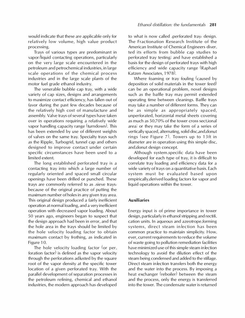
The long established perforated tray is acontacting tray into which a large number ofregularly oriented and spaced small circularopenings have been drilled or punched. Thesetrays are commonly referred to as �sieve trays�because of the original practice of putting themaximum number of holes in any given tray area.This original design produced a fairly inefficientoperation at normal loading, and a very inefficientoperation with decreased vapor loading. About50 years ago, engineers began to suspect thatthe design approach had been in error, and thatthe hole area in the trays should be limited bythe hole velocity loading factor to obtainmaximum contact by frothing, as indicated inFigure 10.
The hole velocity loading factor (or per-foration factor) is defined as the vapor velocitythrough the perforations adjusted by the squareroot of the vapor density at the specific towerlocation of a given perforated tray. With theparallel development of separation processes inthe petroleum refining, chemical and ethanolindustries, the modern approach has developed
to what is now called �perforated tray� design.The Fractionation Research Institute of theAmerican Institute of Chemical Engineers diver-ted its efforts from bubble cap studies toperforated tray testing; and have established abasis for the design of perforated trays with highefficiency and wide capacity range (RaphaelKatzen Associates, 1978).
Where foaming or tray fouling (caused bydeposition of solid materials in the tower feed)can be an operational problem, novel designssuch as the baffle tray may permit extendedoperating time between cleanings. Baffle traysmay take a number of different forms. They canbe as simple as appropriately spaced,unperforated, horizontal metal sheets coveringas much as 50-70% of the tower cross sect-ionalarea; or they may take the form of a series ofvertically spaced, alternating, solid disc-and-donutrings (see Figure 7). Towers up to 13ft indiameter are in operation using this simple disc-and-donut design concept.
Although system-specific data have beendeveloped for each type of tray, it is difficult tocorrelate tray loading and efficiency data for awide variety of trays on a quantitative basis. Eachsystem must be evaluated based uponempirically-derived loading factors for vapor andliquid operations within the tower.
Auxiliaries
Energy input is of prime importance in towerdesign, particularly in ethanol stripping and rectifi-cation units. In aqueous and azeotrope-formingsystems, direct steam injection has beencommon practice to maintain simplicity. How-ever, current requirements to reduce the volumeof waste going to pollution remediation facilitieshave minimized use of this simple steam injectiontechnology to avoid the dilution effect of thesteam being condensed and added to the stillage.Direct steam injection transfers both the energyand the water into the process. By imposing aheat exchanger (reboiler) between the steamand the process, only the energy is transferredinto the tower. The condensate water is returned
282 R. Katzen, P.W. Madson and G.D. Moon, Jr.
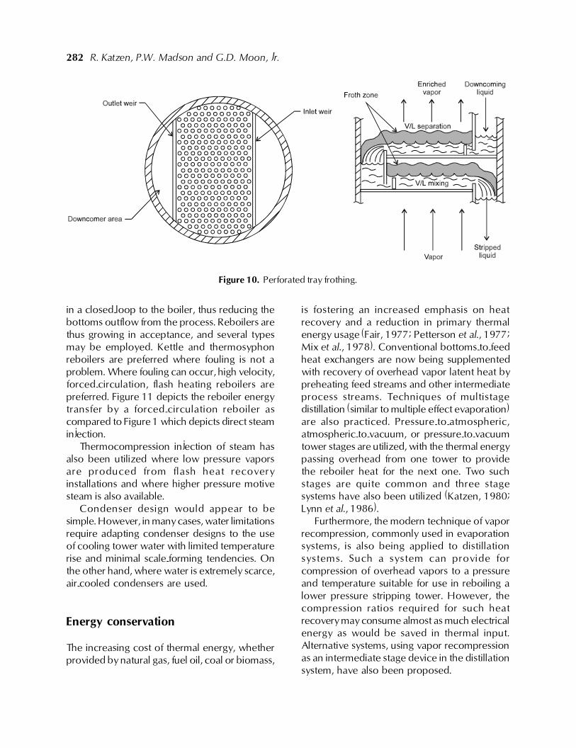
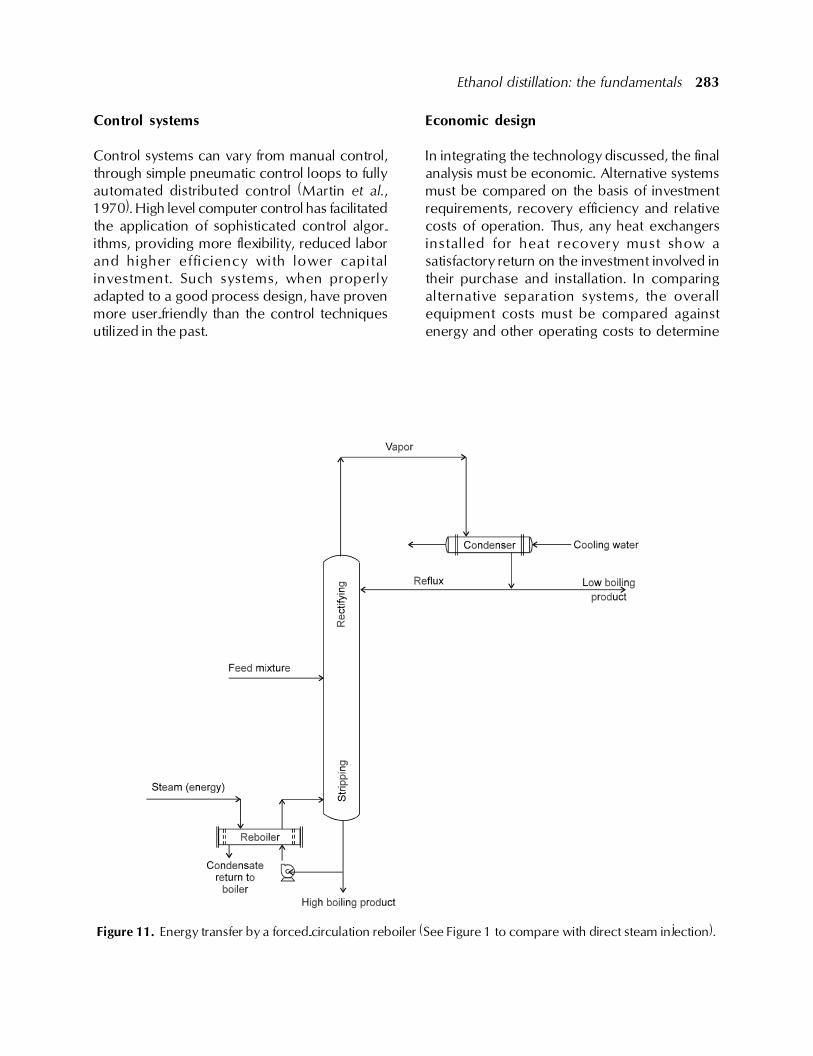
in a closed-loop to the boiler, thus reducing thebottoms outflow from the process. Reboilers arethus growing in acceptance, and several typesmay be employed. Kettle and thermosyphonreboilers are preferred where fouling is not aproblem. Where fouling can occur, high velocity,forced-circulation, flash heating reboilers arepreferred. Figure 11 depicts the reboiler energytransfer by a forced-circulation reboiler ascompared to Figure 1 which depicts direct steaminjection.
Thermocompression injection of steam hasalso been utilized where low pressure vaporsare produced from flash heat recoveryinstallations and where higher pressure motivesteam is also available.
Condenser design would appear to besimple. However, in many cases, water limitationsrequire adapting condenser designs to the useof cooling tower water with limited temperaturerise and minimal scale-forming tendencies. Onthe other hand, where water is extremely scarce,air-cooled condensers are used.
Energy conservation
The increasing cost of thermal energy, whetherprovided by natural gas, fuel oil, coal or biomass,
is fostering an increased emphasis on heatrecovery and a reduction in primary thermalenergy usage (Fair, 1977; Petterson et al., 1977;Mix et al., 1978). Conventional bottoms-to-feedheat exchangers are now being supplementedwith recovery of overhead vapor latent heat bypreheating feed streams and other intermediateprocess streams. Techniques of multistagedistillation (similar to multiple effect evaporation)are also practiced. Pressure-to-atmospheric,atmospheric-to-vacuum, or pressure-to-vacuumtower stages are utilized, with the thermal energypassing overhead from one tower to providethe reboiler heat for the next one. Two suchstages are quite common and three stagesystems have also been utilized (Katzen, 1980;Lynn et al., 1986).
Furthermore, the modern technique of vaporrecompression, commonly used in evaporationsystems, is also being applied to distillationsystems. Such a system can provide forcompression of overhead vapors to a pressureand temperature suitable for use in reboiling alower pressure stripping tower. However, thecompression ratios required for such heatrecovery may consume almost as much electricalenergy as would be saved in thermal input.Alternative systems, using vapor recompressionas an intermediate stage device in the distillationsystem, have also been proposed.
Figure 10. Perforated tray frothing.
Ethanol distillation: the fundamentals 283
Control systems
Control systems can vary from manual control,through simple pneumatic control loops to fullyautomated distributed control (Martin et al.,1970). High level computer control has facilitatedthe application of sophisticated control algor-ithms, providing more flexibility, reduced laborand higher efficiency with lower capitalinvestment. Such systems, when properlyadapted to a good process design, have provenmore user-friendly than the control techniquesutilized in the past.
Economic design
In integrating the technology discussed, the finalanalysis must be economic. Alternative systemsmust be compared on the basis of investmentrequirements, recovery efficiency and relativecosts of operation. Thus, any heat exchangersinstalled for heat recovery must show asatisfactory return on the investment involved intheir purchase and installation. In comparingalternative separation systems, the overallequipment costs must be compared againstenergy and other operating costs to determine
Figure 11. Energy transfer by a forced-circulation reboiler (See Figure 1 to compare with direct steam injection).
284 R. Katzen, P.W. Madson and G.D. Moon, Jr.
which system offers the best return. Moderncomputer-assisted designs incorporateeconomic evaluation factors so eco-nomicoptimization can be determined rapidly.
Ethanol distillation/dehydration: specificsystems technology
Proven industrial technologies are available fordistillation of various grades of ethanol from grain,sugarcane, molasses and other feedstocks.Improvements have been made over the years,particularly during development of the motor fuelgrade ethanol industry. In such installations, a keyrequirement is the mini-mization of total energyusage.
The operation that has been most subject tocritical comment is the distillation process. Manyrelatively new �authorities� in the field have basedtheir criticism on technologies that go back 50-60 years, and have created an unwarrantedcondemnation of distillation as a viable processfor low energy motor fuel grade ethanolproduction. Systems developed over the yearswill be described to show that much of suchcriticism is unwarranted and unjustified.
Production of industrial ethanol
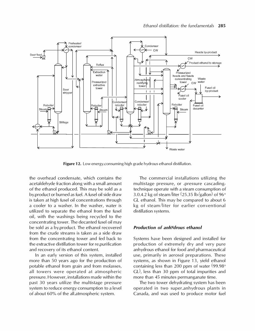
Prior to the recent emphasis on motor fuel gradeethanol, the major ethanol product utilizedworldwide was high purity, hydrous industrialethanol, which is generally produced at astrength of 96o GL (192o US proof) (oGL =degress Gay Lussac = % by volume ethanol; USproof = 2 x % by volume ethanol). Efficient sys-tems have been in commercial operation formany years for the production of such highgrade ethanol from ethylene, grain, molasses andsulfite waste liquor. The basic distillation systemis shown in Figure12.
In the case of synthetic ethanol (outside thescope of this publication), the beer strippingtower is not required and the refining system isa simple three tower unit, which achieves 98%recovery of the ethanol in the crude feed as a
first grade product. The final product may containless than 30 ppm total impurities and has a�permanganate time� of more than 60 minutes.
For the production of industrial or beveragespirit products made by fermentation of grain,molasses or sulfite liquor, the system utilizes thefull complement of equipment shown in Figure12. The beer feed is preheated from the normalfermentation temperature in several stages,recovering low level and intermediate level heatfrom effluent streams and vapors in the process.This preheated beer is degassed and fed to thebeer stripper, which has stripping trays below thebeer feed point and several rectifying trays aboveit. The condensed high wines from the top ofthis tower are then fed to the extractive distillationtower, which may operate at a pressure in theorder of 6-7 bars (87-101.5 psi). In this tower,most of the impurities are removed and carriedoverhead to be condensed as a low gradeethanol stream, from which a small purge ofheads (acetaldehyde and other low boilingimpurities) may be taken while the primarycondensate flow is fed to the concentratingtower. The purified, diluted ethanol from thebottom of the extractive distillation tower is fedto the rectifying tower, which has an integralstripping section. In this tower, the high gradeethanol product, whether industrial or potable,is taken as a side draw from one of the uppertrays. A small heads cut is removed from theoverhead condensate. Fusel oils (mixtures ofhigher alcohols such as propyl, butyl, and amylalcohols and their isomers, which arefermentation by-products or �congeners�) aredrawn off at two points above the feed tray butbelow the product draw tray to avoid a buildupof fusel oil impurities in the rectifying tower. Theoverhead heads cut and the fusel oil draws arealso sent to the concentrating tower.
It should be noted that the rectifying tower isheated by vapors from both the pressurizedextractive distillation tower and the pressurizedconcentrating tower.
In the concentrating tower, the variousstreams of congener-containing draws areconcentrated. A small heads draw is taken from
Ethanol distillation: the fundamentals 285
the overhead condensate, which contains theacetaldehyde fraction along with a small amountof the ethanol produced. This may be sold as aby-product or burned as fuel. A fusel oil side drawis taken at high fusel oil concentrations througha cooler to a washer. In the washer, water isutilized to separate the ethanol from the fuseloil, with the washings being recycled to theconcentrating tower. The decanted fusel oil maybe sold as a by-product. The ethanol recoveredfrom the crude streams is taken as a side drawfrom the concentrating tower and fed back tothe extractive distillation tower for re-purificationand recovery of its ethanol content.
In an early version of this system, installedmore than 50 years ago for the production ofpotable ethanol from grain and from molasses,all towers were operated at atmosphericpressure. However, installations made within thepast 30 years utilize the multistage pressuresystem to reduce energy consumption to a levelof about 60% of the all-atmospheric system.
The commercial installations utilizing themultistage pressure, or �pressure cascading�technique operate with a steam consumption of3.0-4.2 kg of steam/liter (25-35 lb/gallon) of 96o
GL ethanol. This may be compared to about 6kg of steam/liter for earlier conventionaldistillation systems.
Production of anhydrous ethanol
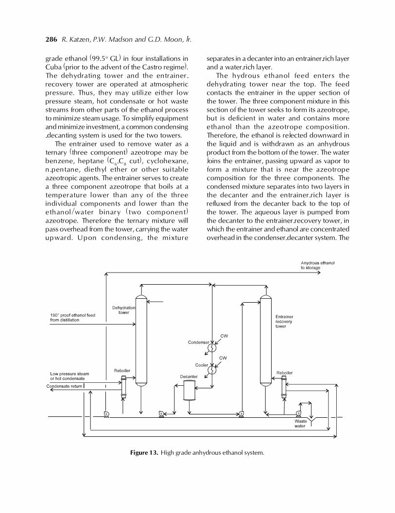
Systems have been designed and installed forproduction of extremely dry and very pureanhydrous ethanol for food and pharmaceuticaluse, primarily in aerosol preparations. Thesesystems, as shown in Figure 13, yield ethanolcontaining less than 200 ppm of water (99.98o
GL), less than 30 ppm of total impurities andmore than 45 minutes permanganate time.
The two tower dehydrating system has beenoperated in two super-anhydrous plants inCanada, and was used to produce motor fuel
Figure 12. Low energy-consuming high grade hydrous ethanol distillation.
286 R. Katzen, P.W. Madson and G.D. Moon, Jr.
grade ethanol (99.5o GL) in four installations inCuba (prior to the advent of the Castro regime).The dehydrating tower and the entrainer-recovery tower are operated at atmosphericpressure. Thus, they may utilize either lowpressure steam, hot condensate or hot wastestreams from other parts of the ethanol processto minimize steam usage. To simplify equipmentand minimize investment, a common condensing-decanting system is used for the two towers.
The entrainer used to remove water as aternary (three component) azeotrope may bebenzene, heptane (C6-C8 cut), cyclohexane,n-pentane, diethyl ether or other suitableazeotropic agents. The entrainer serves to createa three component azeotrope that boils at atemperature lower than any of the threeindividual components and lower than theethanol/water binary (two component)azeotrope. Therefore the ternary mixture willpass overhead from the tower, carrying the waterupward. Upon condensing, the mixture
separates in a decanter into an entrainer-rich layerand a water-rich layer.
The hydrous ethanol feed enters thedehydrating tower near the top. The feedcontacts the entrainer in the upper section ofthe tower. The three component mixture in thissection of the tower seeks to form its azeotrope,but is deficient in water and contains moreethanol than the azeotrope composition.Therefore, the ethanol is rejected downward inthe liquid and is withdrawn as an anhydrousproduct from the bottom of the tower. The waterjoins the entrainer, passing upward as vapor toform a mixture that is near the azeotropecomposition for the three components. Thecondensed mixture separates into two layers inthe decanter and the entrainer-rich layer isrefluxed from the decanter back to the top ofthe tower. The aqueous layer is pumped fromthe decanter to the entrainer-recovery tower, inwhich the entrainer and ethanol are concentratedoverhead in the condenser-decanter system. The
Figure 13. High grade anhydrous ethanol system.
Ethanol distillation: the fundamentals 287
stripped water, emerging from the base of thetower, may go to waste. If it has substantialethanol content, it may be recycled to the beerwell feeding the spirit unit, but this introducesthe risk of traces of the entrainer in the hydrousethanol which may not all be sent to thedehydration system. This system operates witha steam consumption of 1-1.5 kg/liter (8.3-12.5lb/gallon) of anhydrous ethanol depending onthe quality of product required. As indicatedabove, a major part of the equivalent steamenergy can be provided by hot condensate andhot waste streams from the spirit unit.
Production of anhydrous motor fuel gradeethanol
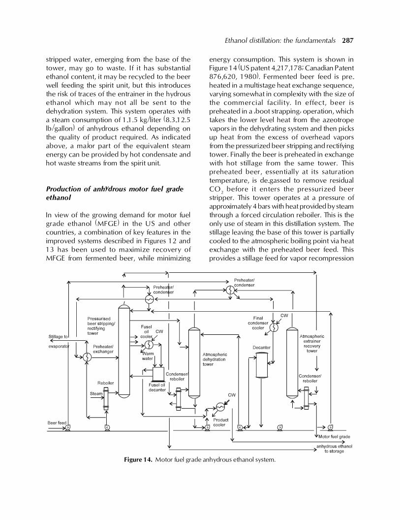
In view of the growing demand for motor fuelgrade ethanol (MFGE) in the US and othercountries, a combination of key features in theimproved systems described in Figures 12 and13 has been used to maximize recovery ofMFGE from fermented beer, while minimizing
energy consumption. This system is shown inFigure 14 (US patent 4,217,178; Canadian Patent876,620, 1980). Fermented beer feed is pre-heated in a multistage heat exchange sequence,varying somewhat in complexity with the size ofthe commercial facility. In effect, beer ispreheated in a �boot strapping� operation, whichtakes the lower level heat from the azeotropevapors in the dehydrating system and then picksup heat from the excess of overhead vaporsfrom the pressurized beer stripping and rectifyingtower. Finally the beer is preheated in exchangewith hot stillage from the same tower. Thispreheated beer, essentially at its saturationtemperature, is de-gassed to remove residualCO2 before it enters the pressurized beerstripper. This tower operates at a pressure ofapproximately 4 bars with heat provided by steamthrough a forced circulation reboiler. This is theonly use of steam in this distillation system. Thestillage leaving the base of this tower is partiallycooled to the atmospheric boiling point via heatexchange with the preheated beer feed. Thisprovides a stillage feed for vapor recompression
Figure 14. Motor fuel grade anhydrous ethanol system.
288 R. Katzen, P.W. Madson and G.D. Moon, Jr.
evaporation at an ideal temperature, requiringneither preheat nor flashing in the evaporator.
The ethanol stripped from the beer in thelower part of the beer tower is rectified toapproximately 95o GL and taken as a side drawa few trays below the top of the rectifying section.The overhead vapors, under pressure, are usedto boil up the atmospheric dehydration towerand the atmospheric entrainer recovery tower,as well as to provide preheat to the beer feed.The condensed overhead vapors are refluxedto the top of the pressurized beer tower, with asmall draw of heads taken to avoid accumulationsof the more volatile congeners such asacetaldehyde. The heads stream, amounting toless than 1% of ethanol production, can beburned as fuel in the plant boiler or sent directlyinto the MFGE final product, thus bypassing thedehydration system.
Side stream fusel oil draws are also takenfrom the rectifying section of the pressurizedtower to a fusel oil decanter. The aqueouswashings are returned to the beer strippingsection of this tower; while the decanted,washed fusel oil is combined with the anhydrousethanol plant. Fusel oil not only has a higher fuelvalue than ethanol, but serves as a blending agentbetween the ethanol and gasoline.
The 95o GL ethanol entering the atmosphericdehydration tower is dehydrated in the mannerpreviously described. Steam consumption in thissystem, varying somewhat with the percentageof ethanol in the beer, is in the range of 1.8-2.5kg/liter (15-21 lb/gallon).
References
Bravo, J.L. et al. 1985. Hydrocarbon Proc. Jan.p.91.
Katzen, R. 1955. Chem. Eng. Nov. p. 209.Fair, J.R. 1977. Chem. Eng. Prog. Nov. p. 78.Fair, J.R. et al. 1990. Chem. Eng. Prog. Jan. p. 19.Katzen, R. 1980. Low energy distillation systems.
Bio-Energy Conference, Atlanta, GA, April.Kister, H.Z. et al. 1990. Chem. Eng. Prog. Sept. p.
63.Lynn, S. et al. 1986. Ind. & Eng. Chem. 25:936.Martin, R. L. et al. 1970. Hydrocarbon Proc. March
1970, p. 149.Mix, T.J. et al. 1978. Chem. Eng. Prog. April p. 49.Petterson, W.C. et al. 1977. Chem. Eng. Sept. p.
79.Robinson and Gilliland. 1950. Elements of
Fractional Distillation, McGraw Hill Book Co.,Inc.