chapter 18 interactive computer aided infrastructure ... · chapter 18 interactive computer aided...
TRANSCRIPT
Chapter 18
Interactive Computer Aided Infrastructure Design and GIS .. the Future?
A. R.V. Ribeiro OWN Systems Inc. #200, 11133-124 Street, Edmonton, Alberta, T5M OJ2
This chapter provides an overview of interactive computer aided infrastructure design, or more generally computer aided engineering (CAE) and geographic information systems (GIS), how the technology has developed to today, and what its future holds.
18.1 Introduction
In the last ten years the personal computer industry has experienced an explosive growth in power and capability at a corresponding exponential decline in cost per megahertz of the central processing unit (CPU). The industry has gone from 8 bit processing in the early eighties to 32 bit processing today. In terms of processing capability we have gone from PC machines with under one million instruction sets per second (MIPS) to machines now with up to 15 MIPS, which brings the technology
Ribeiro, A. 1993. "Interactive Computer Aided Infrastructure Design and GIS- The Future?" Journal of Water Management Modeling Rl75-18. doi: I 0.14796/JWMM.Rl75-18. ©CHI 1993 www.chijournal.org ISSN: 2292-6062 (Formerly in New Techniques for Modelling the Management of Stormwater Quality Impacts. ISBN: 0-87371-898-4)
395

396 CAD AND GIS INFRASTRUCTURE DESIGN
close to that of workstations of a few years ago and exceediIig mainframes of a decade ago.
The area of geographic infonnation systems (GIS) has evolved from the earliest civilization's need for maps for trade and military purposes (Hodgkiss, 1981) and in Roman times, the agrimensores, or land surveyors for government taxation (Dilke, 1971) to modem uses of resource, urban, and infrastructure development.
The evolution of the PC has been matched with a parallel progress in surveying and mapping technologies, such as laser survey instruments and digital storage of survey data. On the mapping side we have the development of highly accurate digital analytical stereo plotters and orthophoto technology; for remote sensing we have Landsat and SPOT imagery which can provide raster pixel resolution to 10 by 10m.
Similarly we have seen development of computer aided engineering (CAE) software which complements computer aided drafting (CAD) packages.
In many ways the GIS and the CAE industry has evolved independently with few of the systems being integrated. What is needed is an integration of raster/vector techniques in GIS and an integration of infrastructure design and GIS.
18.2 Geographic Information Systems (GIS)
18.2.1 Maps and Spatial Information
With the industrial revolution and the resultant increase in demand for resources, the demand for topographic and thematic maps accelerated greatly. In the twentieth century, stereo aerial photography and remotely sensed imagery have allowed photogrammetrists to map large areas with greater and greater accuracy. Geologists, soil scientists, ecologists, urban planners and engineers now have a source of useful infonnation for resource extraction and management In more recent times the same data is now seen as an important source for environmental
18.2 GEOGRAPIDC INFORMATION SYSTEMS 397
impact assessments (e.g. Brinkman and Smyth, 1973. FAO, 1976). The mathematical techniques for spatial analysis was not
developed until the 1930s and 1940s in parallel with developments in statistical methods and time series analysis. However the lack of computing tools hindered any practical progress in the field until the 1960s with the advent of the digital computer. At this point the conceptual methods for spatial analysis and the potential of quantitative thematic mapping and spatial analysis began to flourish (Cliff and Ord, 1981; Ripley, 1977; Webster. 1977).
Prior to the use of computers for mapping the spatial database was a hard copy drawing on paper or film. The information comprised lines, points, areas and. symbols which are explained in the legend. Additional information which could not be described directly on the sheet were referenced to external printed material, reports, memoirs, appendices, etc. Therefore most hard copy maps have the following in common:
1. the original data had to be simplified (classified) or reduced;
2. maps had to be drawn accurately;
3. large areas could only be represented on a number of separate map sheets (depending on scale);
4. it was difficult and expensive to extract hard copy data for use with other spatial data; and
5. they were static qualitative documents which were difficult to update and almost impossible for presenting quantitative information.
Because of the prohibitive costs of generating hard copy maps, they are normally used and are considered relevant for 20 years or more.

398 CAD AND GIS INFRASTRUCTURE DESIGN
18.2.2 Computed Aided Mapping and Analysis
With the development of new trends for resource assessment, land evaluation and planning in the 1960s and 1970s, people began to demand an integrated, multidisciplinary method to analyze the mapped data. There are two approaches: (i) the "gestalten method (Hopkins, 1977) which attempts to fmd "naturally occurring" environmental units that can be recognized, described and mapped in tems of the total interaction of the attributes under study, and (ii) the more conventional "monodisciplinary" resource maps, such as those of geology. landform, soil, vegetation and land use. The former has proven to be too general and difficult for retrieval of specific information about attributes. So there has remained a market for the more conventional monodisciplinary maps.
Engineers and planners in particular, in North America, have realized that data from several monodisciplinary surveys can be combined and integrated by overlaying transparent copies of resource maps to derive resultant polygons of specific combinations (McHarg, 1969). One of the first computer packages to use this approach was SYMAP (Fisher, 1978), short for SYnagraphic MApping (Greek origin synagein, meaning to bring together). which includes a set of modules for analyzing data. manipulating them to produce choropleth or isoline interpolations. and allows results to be printed with overprinting of line printer characters to produce gray scales. A number of raster or grid cell mapping programs followed this development.
The raster-based maps did not receive acceptance by cartographers who continued with their high-quality hard-copy maps till 1977. by which time the experience of using computers in map-making had advanced enough that Rhind (1977) was able to present the following list of reasons for using computers for cartography:
1. to make existing maps more quickly;
2. to make existing maps more cheaply;
18.2 GEOGRAPHIC INFORMATION SYSTEMS 399
3. to make maps for specific user needs;
4. to make map production possible in situations where skilled staff are unavailable;
5. to allow experimentation with different graphical representations of the same data;
6. to facilitate map making and updating when the data are already in digital form;
7. to facilitate analysis of data that demand interactions between statistical analysis and mapping;
8. to minimize the use of printed maps as a data store and thereby to minimize the effects of classification and generalization on the quality of the data;
9. to create maps that are difficult to make by hand, e.g., 3D maps or stereoscopic maps;
10. to create maps in which selection and generalization procedures are explicitly defmed and consistently executed; and
11. to allow for savings and improvements through a review of the whole map-making process as a result of automation.
By the late 19708, in North America, a considerable investment in the development and application of computer~aided cartography had been undertaken by govennnent and private agencies (Tomlinson et al., 1976; Teicholz and Berry, 1983). Unfortunately this did not result in immediate and direct savings in costs. Hardware was expensive and trained staff was and still is in short supply. As a result many problems and issues are still prevalent today. Technological development, particularly in

400 CAD AND GIS INFRASTRUCTURE DESIGN
hardware, has often outstripped management's ability to keep up. Indeed many cartographers miss the opportunity that digital mapping has provided them and instead have used the technology merely to produce maps more accurately and quickly. A comment which may be applied not only to cartographers but to engineers as well, was made by Poiker (1982) "computer cartography is like a person with the body of an athlete in his prime time and the mind of a child".
Computerized cartography has been primarily directed to automating existing manual methods rather than exploring new ways to handle spatial data, in spite of the cost and many man years of development. The results from the 19608 and 19708 development in mapping can be summarized as an automation of existing tasks with emphasis on accuracy and visual quality and spatial analysis (raster) at the expense of good graphical results. This is changing today albeit too slowly for many.
18.2.3 Geographic Information Systems (GIS)
A number of fields have grown concurrently with computerized mapping and spatial analysis. These are cadastral and topographic mapping. thematic cartography, civil engineering. geography, mathematics of spadal variation, soil science, surveying and photogrammetry, rural and urban planning. utility networks, remote sensing and image analysis. Although initially there has been a duplication of effort for the different applications, the concurrent development results in the possibility of linking many kinds of spatial data processing together into a truly general-purpose GIS (Figure 18.1).
Workers in all disciplines wish to develop a powerful set of tools for collecting. storing, retrieving. transforming and displaying spatial data from the real world for their particular pmposes. This set of tools constitutes a "Geographical Information System" (or GIS). Geographical data describe objects from the real world in terms of: (a) their position with respect to a known coordinate system, (b) their attributes that are unrelated

18.2 GEOORAPIDC INFORMATION SYSTEMS 401
Cartography tbigb quality drafting)
Compmer Aided Design and Computer Graphics
SUlVOying and Photogrammeuy
S!,atial Analysis using rasrar data from thematic :naps
Interpolation from point data
Remote Sensing Toc:bnology
TIME
GIS
TECHNICAL AND CONCEPTUAL DEVELOPMENT
Figure 18.1: GIS linking parallel developments.
to position (such as soil type, cost, pH, etc.) and (c) their spatial interrelations with each other (topological relations), which describe how they are linked together or how one can travel between them (Burrogh, 1986).
Although there are a lot of similarities between CAD and GIS they are not the same. The major difference is the need of GIS to handle a diversity of data and the analysis methods used. Because of this, many original GIS systems were designed independently with their own graphics engine. More recently, advanced CAD systems have allowed third party application developers to build a GIS system around their CAD engine. The efficiency and functionality vary from one CAD system to another.
A GIS system is more than a mapping system because data
402 CAD AND GIS INFRASTRUCTURE DESIGN
can be accessed, transfonned and manipulated interactively. They can be used to study environmental processes or to analyze results of trends, or to anticipate results of different planning decisions. The GIS system can be used to model the consequences of a course of action before the mistakes have been irrevocably made in the landscape itself. With concerns today of environmental impacts of development, the GIS ability to analyze becomes more and more relevant.
18.2.4 The Components of a GIS
A GIS has three important components: (i) computer hardware, (ii) sets of application modules, and (iii) a proper organizational context. These need to be balanced if the system is to function properly.
The basic hardware components are: (i) the central processing unit (CPU), (U) the visual display unit (VDU or monitor), (iii) the input device or digitizer (or mouse), (iv) the storage device or hard disk drive, (v) the backup device or tape drive, and (vi) the output device or plotter.
The software package for a GIS system consists of five basic technical modules (Figure 18.2):
1. data input and verification; 2. data storage and database management; 3. data analysis and transfonnation; 4. data output and presentation; and 5. interaction with the user.
Data input is the process of transfonning data captured from existing maps, field observations, aerial photography and satellite imagery into a graphical database (Figure 18.3). Data storage and database management concerns the linkage (topology) of the graphical elements with the attribute database via the database management system (DBMS). Data transfonnation contains two types of operations: (0 transfonnations to data to bring them up

18.2 GEOGRAPHIC INFORMATION SYSTEMS 403
~ \ 'I I ,--_-L-____ ___, \
I i QuervH I • i Geographic \ '- '! Database I ,
~' i
r Display I r~T-ran'-%'Y-st--o-rm-4"-at-io-n~1 I and II Analysis i/! I I \.. )
I ReDoning i / ~--.J
i
Figure 18.2: Main software components of a GIS.
to date, match other data and remove errors, and (ii) data analyses applied to achieve answers to queries (such as polygon overlays, unions. etc.). Transformations can operate on the spatial and non-spatial aspects of the data, either separately or in combination. Data output is the process of displaying results for presentation in the form of maps, tables and figures. The final module or interaction with user - query input - is one of the more critical components. Today query input is generally made through a menu driven environment.
The effectiveness of a successful GIS system is governed by its organizational structure. It is not sufficient to purchase hardware and software, it is most critical that personnel and managers be retrained to use the new technology in an organizational context as shown in Figure 18.4.

404 CAD AND GIS INFRASlRUCfURE DESIGN
( Existing maps ) ( Field observations ) (Sensors)
Information for
Management
DATA INPUT
Figure 18.3: GIS data input.
MANAGEMBNT
t ( Data gathering
Aims and queries ftom
Management
Figure 18.4: Organization aspects of GIS.

18.3 INFRASTRUCTURE DESIGN 405
18.3 Infrastructure Design
Only twenty years ago engineers were just starting to use hand held calculators for design. Any programming required main frame or mini-computers with batch processing. Up and until PCbased computer-aided-drafting (CAD), much of the infrastructure design was done manually. Even today a large segment of engineering is not automated. There has been a dramatic increase in the last five years because of the increase in the availability of computer-aided-engineering (CAE) software for infrastructure design. Additional benefits have accrued due to the increasing computing power of the PC hardware systems.
Unfortunately many of the CAE packages have been designed to merely duplicate the old design process, similar to the evolution in digital cartography. This decreased the production process and cost. but did not add to the digital information base. There is still a large amount of duplication in the design office. Instead of having manually-drawn as-built plans there are digital CAD plots and disks in the archive. Computer printouts together with computerized files of input data and reports replaced manual design sheets.
18.3.1 Computer Aided Engineering and Design
CAE and CAD technology and development flourished in the mid 1980s together with that of the PCs. However. its initial emphasis was automation of the manual process. This is partly because integration was not possible due to the immaturity of the technology and secondly because of the conservative nature of the design community.
Take the case of civil site design; engineers still compute volumetrics for many earthworks projects by cross-sections and the average-end-area method. With digital terrain models (DTM), earthworks can be computed more accurately with the prismoidal method using the triangulated irregular network (TIN) surfaces of the original ground and final design. With the availability of

406 CAD AND GIS INFRASTRUCTURE DESIGN
DTM software packages on PCs, more consultants are now taking advantage of the improvements in technology.
Similarly survey instruments have advanced in technology. Now many in the industry are using electronic and laser surveying equipment. With a total station, a site can be surveyed easily with the information stored digitally on a data collector. A digital elevation model (DEM) of random masspoints and breaklines for the site can be collected instead of a set of xy grid points. Similarly DEMs can be collected for road and drainage projects instead of the traditional traverse and level survey for cross-sectional information.
18.3.2 Case Example: Subdivision Design
In order to demonstrate change in the technology of infrastructure design a case study using a typical subdivision development process will be used.
Past and Current Approach - Manual Process
Subdivision development was and is today still being designed in a sequential, monodisciplinary process as shown in Figure 18.5. The main sequence for a typical subdivision development is:
1. a subdivision project is initiated;
2. a mapping company generates a hard copy topographic map of the site, or a grid survey is undertaken;
3. the planner lays out the subdivision plan using the map;
4. the surveyor determines the legal description of the lots, etc. (cadastre);
5. the engineer does the grading plan;

18.3 INFRASTRUCTURE DESIGN 407
6. the engineer/designer lays out the storm network;
7. the engineer/designer calculates the runoff and designs the pipe sizing, manually or with simulation models;
8. the designer/draftsman plots the plan and profile information;
9. the bill of material is extracted for the tender documents;
10. the process is repeated for sanitary, water, etc;
11. the project is tendered and constructed; and
12. on completion the as-built information is prepared and submitted to the local agency.
Current and Future Approach - Automated Process
Using computer aided interactive infrastructure design modules and GIS the process can be improved by using the multidisciplinary approach with the GIS as the central focal point for the design team. Geographic data can be readily accessed by all members and inter-disciplinary communication and feedback between team members will assist in the optimization of the design process.
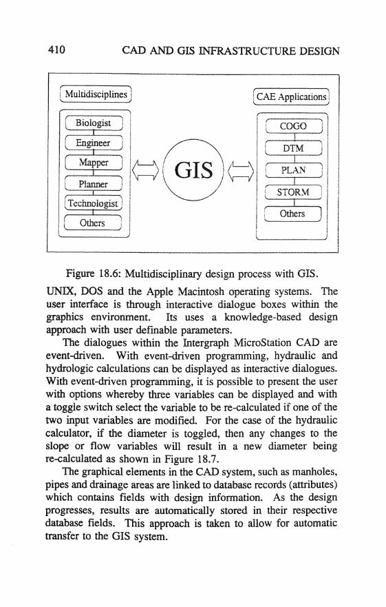
Similarly the CAE application software must also work together in an integrated manner so that relevant information can pass from one module to another with minimal modifications and conversion as shown in Figure 18.6. COGO, DTM, GIS, PLAN and STORM are CAE application modules (GWN Systems Inc., 1987-1992), for coordinate geometry design, digital terrain modelling for site works, geographic information system, subdivision baseplan design and storm drainage design respectively. The system is summarised:
408 CAD AND GIS INFRASTRUCTURE DESIGN
( Stan Project i
) 'V r ~apping "\ ~f Hard copy map '\
i '-. )~" ./
r Planning "'\ 'r Subdivision plan '\
"-) , ;; I
~'~ ./
( Surveying "\ ' " )of Legal plan
'\
\ I ,J~ \.
,/
/ Grading \ )of " \ )~\
Grading plan )
( Design \ )01. I ) ~. \.. DesIgn results ./
( Drafting ) .. ' .. ){Plan/profile drawings) "-
).4:-( :)or " Tender Tender quantities 1
\. ) ,J;. ( Drafting )o( As-built drawings
'\
,J )
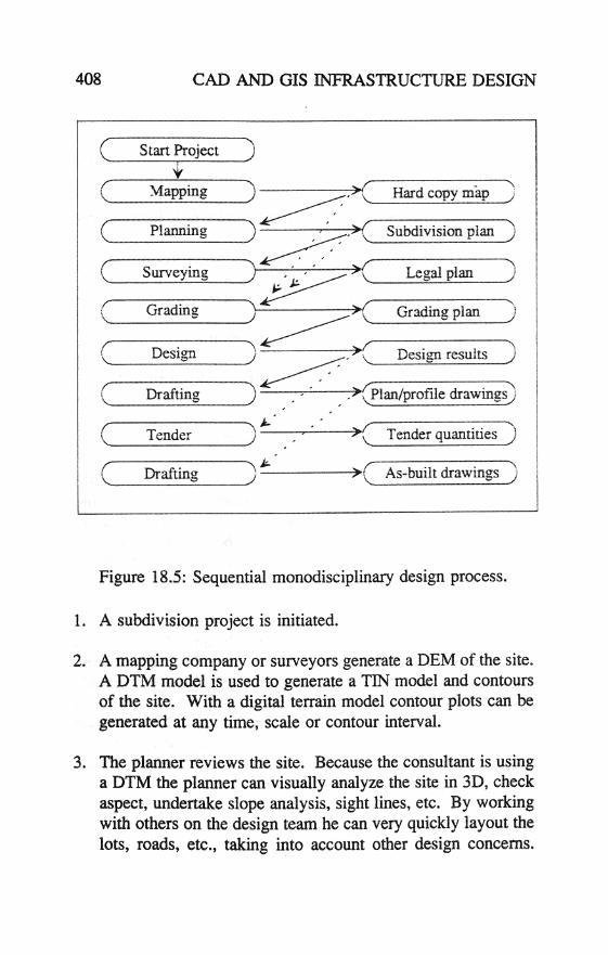
Figure 18.5: Sequential monodisciplinary design process.
1. A subdivision project is initiated.
2. A mapping company or surveyors generate a DEM of the site. A DTM model is used to generate a TIN model and contours of the site. With a digital terrain model contour plots can be generated at any time, scale or contour interval.
3. The planner reviews the site. Because the consultant is using a DTM the planner can visually analyze the site in 3D, check aspect, undertake slope analysis, sight lines, etc. By working with others on the design team he can very quickly layout the lots, roads, etc., taking into account other design concerns.

18.3 INFRASTRUCTURE DESIGN 409
The design can be done digitally with PLAN or similar packages.
4. The surveyor uses COGO to define the legal base and make adjustments as required. Data from PLAN can be used directly, thereby minimizing time required to generate the legal plan.
S. The engineer/designer does grading with PLAN and DTM.
6. The engineer/designer lays out the storm drainage network, manhole locations, drainage areas, etc. with PLAN.
7. The engineer/designer calculates the pipe sizing requirement with STORM using the Rational method or simulation models.
8. The engineer/designer automatically plots the plan and profile drawings using STORM.
9. The engineer/designer automatically extracts the bill of materials from the attribute database with STORM.
10. The process is repeated for sanitary, water, systems, etc.
11. The project is tendered and constructed.
12. On completion the as-built information is prepared digitally and submitted to the local agency together with the database information for inclusion in their GIS system.
18.3.3 A typical Interactive Infrastructure Design Package
GWN-STORM is one module of a series of integrated interactive computer aided design software developed by GWN Systems Inc (1992). It is designed to run on a number of platforms using
410 CAD AND GIS INFRASTRUCTURE DESIGN
[ Multidisciplines ) ( CAE Applications )
Figure 18.6: Multidisciplinary design process with GIS.
UNIX, DOS and the Apple Macintosh operating systems. The user interface is through interactive dialogue boxes within the graphics environment. Its uses a knowledge-based design approach with user defmable parameters.
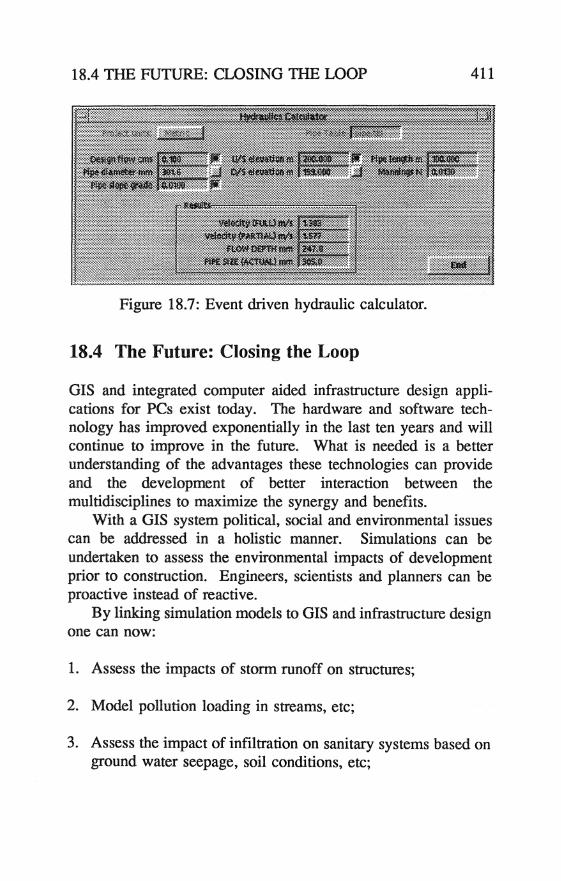
The dialogues within the Intergraph MicroStation CAD are event-driven. With event-driven programming, hydraulic and hydrologic calculations can be displayed as interactive dialogues. With event-driven programming, it is possible to present the user with options whereby three variables can be displayed and with a toggle switch select the variable to be re-calculated if one of the two input variables are modified. For the case of the hydraulic calculator, if the diameter is toggled, then any changes to the slope or flow variables will result in a new diameter being re-calculated as shown in Figure 18.7.
The graphical elements in the CAD system, such as manholes, pipes and drainage areas are linked to database records (attributes) . which contains fields with design information. As the design progresses, results are automatically stored in their respective database fields. This approach is taken to allow for automatic transfer to the GIS system.
18.4 THE FUTURE: CLOSING THE LOOP 411
Figure 18.7: Event driven hydraulic calculator.
18.4 The Future: Closing the Loop
GIS and integrated computer aided infrastructure design applications for PCs exist today. The hardware and software technology has improved exponentially in the last ten years and will continue to improve in the future. What is needed is a better understanding of the advantages these technologies can provide and the development of better interaction between the multidisciplines to maximize the synergy and benefits.
With a GIS system political, social and environmental issues can be addressed in a holistic manner. Simulations can be undertaken to assess the environmental impacts of development prior to construction. Engineers, scientists and planners can be proactive instead of reactive.
By linking simulation models to GIS and infrastructure design one can now:
1. Assess the impacts of storm runoff on structures;
2. Model pollution loading in streams, etc;
3. Assess the impact of infiltration on sanitary systems based on ground water seepage, soil conditions, etc;
412 CAD AND GIS INFRASTRUCTURE DESIGN
4. assess impact of development on wetlands; and
5. site solid waste disposal areas based on polygon analyses.
All the above examples can and are being done without GIS or computer modelling. but these are done at a high cost and as one-off type studies. Without GIS it is very difficult to reassess a different scenario if there are changes in methodology or legal requirements. In addition all the data collected is in hard copy and is usually unavailable. or difficult to transpose for use by others.
r-- , I I , MUL 11DlSCIPLINARY I
PROJECT !
'--__ TE_AM J /-' ~\ \.---v
~~ i l
\
( GIS) \"'~
~ ENVIRONMENTALl
SOCIAL I POU11CALi
ISSUES J
(-----~
INFRAS'IRUCmRE DESIGN
APPUCA TIONS
c ______ ~
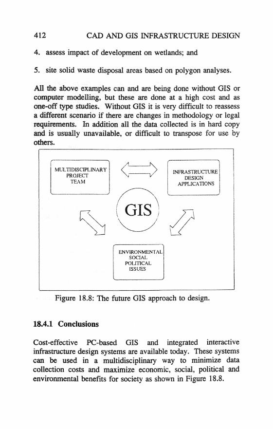
Figure 18.8: The future GIS approach to design.
18.4.1 Conclusions
Cost-effective PC-based GIS and integrated interactive infrastructure design systems are available today. These systems can be used in a multidisciplinary way to minimize data collection costs and maximize economic, social, political and environmental benefits for society as shown in Figure 18.8.

18.5 REFERENCES 413
The technology for GIS and integrated CAE design is available now. Let us all work together to close the loop and move ahead into the future.
18.5 References
Brinkman, R. and Smyth. A.l. (1973). Land evaluation for rural purposes. Summary of an expert consultation, Wageningen, The Netherlands, 6-12 October 1972. International Institute for Land Reclamation and Improvement, Wageningen, Publication No. 17.
Burrough. P.A. (1986). Principles of Geographical Information Systems for Land Resources Assessment. aarendon Press, Oxford.
aiff, A.D. and Ord, I.K. (1981). Spatial processes: models and applications. Pion, London.
DUke, O.A.W. (1971). The Roman land surveyors. An introduction to the agrimensores. David and Charles, Newton Abbot, U.K.
Fisher, H.T. (1978). Thematic cartography - what it is and what is different about it. Harvard papers in theoretical cartography. Laboratory for Computer Graphics and Spatial Analysis. Harvard.
GWN Systems Inc. (1987-1992). GWN-COGO, GWN-DTM, GWN-GIS, OWN-PLAN and OWN-STORM - Computer aided engineering applications. Edmonton. Alberta, Canada.
Hodgkiss, A. O. (1981). Understanding maps. Dawson, Folkestone, U.K.
414 CAD AND GIS INFRASTRUCTURE DESIGN
Hopkins, L.D. (1977). Methods for generating land suitability maps: a comparative evaluation. Am. Inst. Plan. J. October, 386-400.
McHarg, I.L. (1969). Design with nature. Doubleday! Natural History Press, New York.
Poiker, T.K. (formerly Peuker) (1982). Looking at computer cartography. GeoJournal 6, 241-9.
Rhind, D. (1977). Computer aided cartography. Trans. Inst. Br. Geogrs (N.S.) 2, 71-96.
Ripley, B.D. (1981). Spatial statistics. Wiley, New York.
Teicholz, E. and Berry, BJ.L. (1983). Computer graphics and environmental planning. Prentice Hall, Englewood Cliffs, NI.
Tomlinson, R.F. (1984). Geographic infonnation systems - a new frontier. In Proc. Int. Symp. on Spatial Data Handling. 20-24 August, Zurich, pp. 1-14.
Tomlinson, R.F., Calkins, H.W., and Marble, D.F. (1976). Computer handling of geographical data. UNESCO, Geneva.
Webster, R. (1977). Quantitative and numerical methods for soil survey and classification. Oxford University Press, Oxford.