chapter 2 data manipulation. © 2005 pearson addison-wesley. all rights reserved 2-2 chapter 2: data...
TRANSCRIPT
Chapter 2
Data Manipulation

© 2005 Pearson Addison-Wesley. All rights reserved2-2
Chapter 2: Data Manipulation
• 2.1 Computer Architecture
• 2.2 Machine Language
• 2.3 Program Execution
• 2.4 Arithmetic/Logic Instructions
• 2.5 Communicating with Other Devices
• 2.6 Other Architectures

© 2005 Pearson Addison-Wesley. All rights reserved2-3
Computer Architecture
• Central Processing Unit (CPU) or processor– Arithmetic/Logic Unit (ALU)– Control Unit– Registers– Cache Memory
• Bus
• Motherboard

© 2005 Pearson Addison-Wesley. All rights reserved2-4
Stored program concept
• A program is just a special type of data.– A program can be stored in main memory.
• One general-purpose machine can run many different programs.

© 2005 Pearson Addison-Wesley. All rights reserved2-5
Figure 2.1 CPU and main memory connected via a bus

© 2005 Pearson Addison-Wesley. All rights reserved2-6
Machine language: definitions
• Machine instruction = an instruction coded as a bit pattern directly recognizable by the CPU
• Machine language = the set of all instructions recognized by a machine

© 2005 Pearson Addison-Wesley. All rights reserved2-7
Machine language philosophies
• Reduced Instruction Set Computing (RISC)– Few, simple, efficient, and fast instructions– Example: PowerPC from Apple/IBM/Motorola
• Complex Instruction Set Computing (CISC)– Many, convenient, and powerful instructions– Example: Pentium from Intel

© 2005 Pearson Addison-Wesley. All rights reserved2-8
Machine instruction types
• Data Transfer: copy data between CPU and main memory
• Arithmetic/Logic: use existing data values to compute a new data value
• Control: direct the execution of the program

© 2005 Pearson Addison-Wesley. All rights reserved2-9
Figure 2.2 Adding values stored in memory
© 2005 Pearson Addison-Wesley. All rights reserved2-10
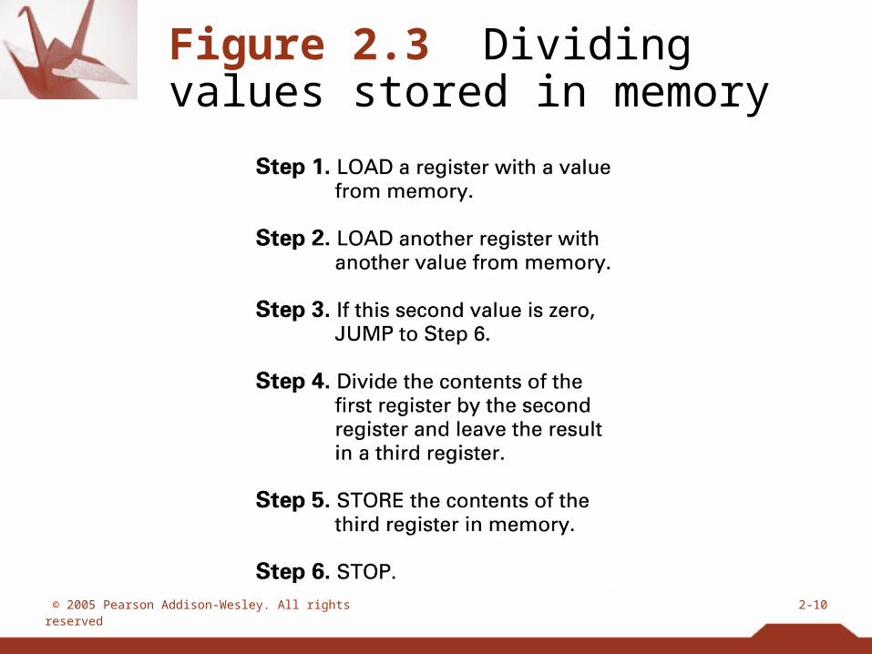
Figure 2.3 Dividing values stored in memory

© 2005 Pearson Addison-Wesley. All rights reserved2-11
Figure 2.4 The architecture of the machine described in Appendix C

© 2005 Pearson Addison-Wesley. All rights reserved2-12
Parts of a machine instruction
• Op-code: specifies which machine operation to execute– One per instruction
• Operand: more detailed information about this operation– Number of operands varies depending on op-code

© 2005 Pearson Addison-Wesley. All rights reserved2-13
Figure 2.5 The composition of an instruction for the machine in Appendix C

© 2005 Pearson Addison-Wesley. All rights reserved2-14
Figure 2.6 Decoding the instruction 35A7

© 2005 Pearson Addison-Wesley. All rights reserved2-15
Figure 2.7 An encoded version of the instructions in Figure 2.2

© 2005 Pearson Addison-Wesley. All rights reserved2-16
Program execution
• Controlled by two special-purpose registers– Program counter: address of next instruction– Instruction register: current instruction
• Steps performed by control unit– Fetch– Decode– Execute

© 2005 Pearson Addison-Wesley. All rights reserved2-17
Figure 2.8 The machine cycle

© 2005 Pearson Addison-Wesley. All rights reserved2-18
Figure 2.9 Decoding the instruction B258
© 2005 Pearson Addison-Wesley. All rights reserved2-19
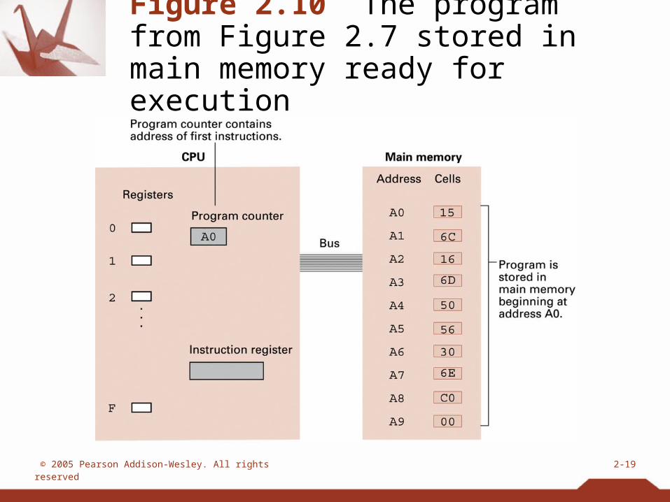
Figure 2.10 The program from Figure 2.7 stored in main memory ready for execution

© 2005 Pearson Addison-Wesley. All rights reserved2-20
Figure 2.11 Performing the fetch step of the machine cycle

© 2005 Pearson Addison-Wesley. All rights reserved2-21
Figure 2.11 Performing the fetch step of the machine cycle (cont’d)

© 2005 Pearson Addison-Wesley. All rights reserved2-22
Arithmetic/Logic operations
• Logic: AND, OR, XOR
• Rotate and Shift: circular shift, logical shift, arithmetic shift
• Arithmetic: add, subtract, multiply, divide– Often separate instructions for different types of
data

© 2005 Pearson Addison-Wesley. All rights reserved2-23
Figure 2.12 Rotating the bit pattern A3 one bit to the right

© 2005 Pearson Addison-Wesley. All rights reserved2-24
Communicating with other devices
• Controller = intermediary device that handles communication between the computer and a device.
• Port = set of addresses assigned to a device.– Memory-mapped I/O: CPU reads from or writes to
addresses of the controller’s port

© 2005 Pearson Addison-Wesley. All rights reserved2-25
Communicating with other devices (continued)
• Direct memory access (DMA): main memory access by a controller over the bus
• Von Neumann Bottleneck: insufficient bus speed impedes performance
• Handshaking: the process of controlling the transfer of data between components of different speeds

© 2005 Pearson Addison-Wesley. All rights reserved2-26
Figure 2.13 Controllers attached to a machine’s bus

© 2005 Pearson Addison-Wesley. All rights reserved2-27
Figure 2.14 A conceptual representation of memory-mapped I/O

© 2005 Pearson Addison-Wesley. All rights reserved2-28
Data communication rates
• Measurement units– Bps = bits per second– Kbps = kilo-bps, or 1,000 bps– Mbps = mega-bps, or 1,000,000 bps– Gbps = giga-bps, or 1,000,000,000 bps
• Bandwidth = maximum available rate

© 2005 Pearson Addison-Wesley. All rights reserved2-29
Data communication path types
• Serial: one line transfers one bit at a time
• Parallel: several lines transfer different bits simultaneously
• Modem: converts between digital bits and analog tones

© 2005 Pearson Addison-Wesley. All rights reserved2-30
Other architectures
• Throughput = (total work) / (total time)
• Technologies to increase throughput– Pipelining: overlap steps of the machine cycle– Parallel processing: use multiple processors
simultaneously• SISD = no parallel processing
• MIMD = different programs, different data
• SIMD = same program, different data