chapter 2 experimental apparatus
TRANSCRIPT
12
CHAPTER 2 EXPERIMENTAL APPARATUS
This chapter describes the wind tunnel, the test model, and the measurement instrumentation used in this experimental study. The glow-discharge equipment is discussed in Chapter 3.
2.1 The Mach 4, Purdue Quiet-Flow Ludwieg Tube
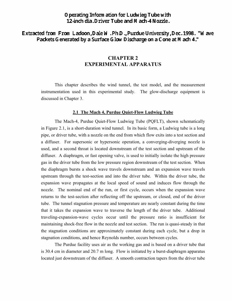
The Mach-4, Purdue Quiet-Flow Ludwieg Tube (PQFLT), shown schematically in Figure 2.1, is a short-duration wind tunnel. In its basic form, a Ludwieg tube is a long pipe, or driver tube, with a nozzle on the end from which flow exits into a test section and a diffuser. For supersonic or hypersonic operation, a converging-diverging nozzle is used, and a second throat is located downstream of the test section and upstream of the diffuser. A diaphragm, or fast opening valve, is used to initially isolate the high pressure gas in the driver tube from the low pressure region downstream of the test section. When the diaphragm bursts a shock wave travels downstream and an expansion wave travels upstream through the test-section and into the driver tube. Within the driver tube, the expansion wave propagates at the local speed of sound and induces flow through the nozzle. The nominal end of the run, or first cycle, occurs when the expansion wave returns to the test-section after reflecting off the upstream, or closed, end of the driver tube. The tunnel stagnation pressure and temperature are nearly constant during the time that it takes the expansion wave to traverse the length of the driver tube. Additional traveling-expansion-wave cycles occur until the pressure ratio is insufficient for maintaining shock-free flow in the nozzle and test section. The run is quasi-steady in that the stagnation conditions are approximately constant during each cycle, but a drop in stagnation conditions, and hence Reynolds number, occurs between cycles. The Purdue facility uses air as the working gas and is based on a driver tube that is 30.4 cm in diameter and 20.7 m long. Flow is initiated by a burst-diaphragm apparatus located just downstream of the diffuser. A smooth contraction tapers from the driver tube

13
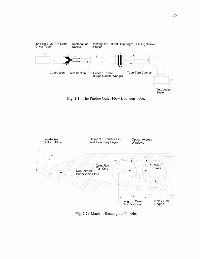
to the first throat, which is followed by a Mach-4 rectangular nozzle, a constant-area test section, a fixed second throat, a diffuser, and a vacuum tank. The nozzle exit and test-section areas are both 97 mm x 109 mm. A schematic of the two-dimensional nozzle is given in Figure 2.2. Optical access to the nozzle flow is provided by two 76 mm diameter windows on each flat sidewall. The nozzle walls are polished throughout, with a rms surface roughness of 0.02-0.04 µm at the throat. A Kulite, model XCQ-062-25A, absolute pressure transducer, mounted flush with the sidewall, is used to monitor the static pressure in the test-section. The large initial drop in static pressure at the tunnel startup serves to verify that Mach 4 flow is obtained in the test-section. For further details on the PQFLT, refer to Munro (1996), Schmisseur et al. (1996), Schneider and Haven (1995), and Schneider et al. (1996). The Reynolds number in the test core of the PQFLT is determined by the driver tube, or stagnation, pressure. The driver tube pressures used in the PQFLT are typically in the range of 75 kPa to 125 kPa. Corresponding stagnation temperatures range from 293 K to 300 K. For atmospheric driver tube conditions, the unit Reynolds number in the test core is on the order of 45,000/cm. The run time depends on model size and the associated pressure losses. The air in the driver tube upstream of the expansion wave is essentially stagnant. At a temperature of 293 K, the speed of sound, a, in the driver tube is 343 m/s, and the duration of one expansion-wave cycle is about
2 20 7
343121
x m
m smsec .
.
/=
Typically, the run time is around 3.5 seconds which allows for approximately 30 traveling expansion-wave cycles. The stagnation pressure and temperature decrease by 35 and 10 percent, respectively, during the 3.5 second run time (Schneider et al., 1994 and 1996). Typical plots showing the variation of the PQFLT nozzle stagnation pressure, p1t , and stagnation temperature, T 1t , with wind-tunnel run time are given in Figures 2.3(a) and 2.3(b). The data in Figure 2.3 have been normalized by the driver-tube pressure, pdo, and temperature, T do , just prior to the start of the run. The stagnation pressure, p1t , was deduced from pitot-probe measurements, p 2t , using standard normal-shock relations (see Schmisseur, 1997). The stagnation temperature was measured with a custom-built14, cold-wire Constant Current Anemometer (CCA) (see Schmisseur, 1997). Note the incremental, or step, decrease every 121 ms Sample pressure and temperature steps at
14 Designed and built by Steven P. Schneider.

14
the beginning, the middle, and near the end of the run are given in Figures 2.4 and 2.5, respectively. Due to the spreading of the expansion waves, the steps become less distinct during the course of a run. Figure 2.4(a) shows that the normalized pressure is less than one at the start of Mach 4 flow in the nozzle. Presumably, this is due to the uncertainty in the Mach number, and, hence, the corresponding pressure ratio, p p1t 2t/ , or to losses that occur during startup, or both. High-speed, quiet-flow wind tunnels require both low levels of noise in the inviscid flow entering the nozzle and laminar boundary layers on the nozzle walls. The flow entering the nozzle of the PQFLT has low noise levels due to three factors. First, flow conditioning, including drying and particle filtering, is performed prior to the run as the driver tube is charged. Second, no mechanical components, such as the burst-diaphragm apparatus, are located upstream of the test section. Third, the flow in the driver tube is essentially accelerated from stagnation conditions and the contraction ratio is large. The combination of these features result in low vorticity (turbulence), entropy (temperature), and acoustic (pressure) fluctuation levels in the inviscid flow entering the nozzle. As mentioned in Chapter 1, turbulent boundary layers on the wind-tunnel walls radiate acoustic noise along eddy-Mach lines. These disturbances increase the noise level in the freestream flow. The Mach-4 PQFLT nozzle, designed and fabricated at NASA Langley in the 1970s, is highly polished, especially at the throat, to avoid roughness-induced transition. For driver tube pressures up to about one atmosphere, the side wall boundary layers are laminar for a sufficiently long distance so that a quiet-flow test core exists in the nozzle. Within the inviscid core flow of the nozzle is a test rhombus of uniform quiet flow. As shown in Figure 2.2, the beginning of this test core corresponds to the nominal onset of uniform Mach-4 flow, and occurs at an axial distance of approximately z = 23.5 cm from the nozzle throat (Schneider and Haven, 1995). The end of the test core is defined by the region affected by turbulent spots which develop on the nozzle walls. In the PQFLT, the axial length of the quiet-flow region, Lq, is typically 10 cm for atmospheric driver tube conditions. The length of the quiet-flow region decreases as the driver tube pressure and, therefore, the tunnel Reynolds number is increased. The transition front of the nozzle-wall boundary layers moves upstream as the Reynolds number increases. For instability and transition experiments, the test models are located within the quiet-flow core of the nozzle rather than in the noisy test-section. In terms of pitot, or total, pressure measurements, a practical criterion for quiet flow is that the ratio of the rms pitot-pressure fluctuations, ′p2rms , to the mean pitot pressure, p2t , be less than

15
about 0.05% (Beckwith and Moore (1982), Beckwith and Miller (1990), and Schneider & Haven (1995)),
′
≤pp2
20 05rms
t. % . (2.1)
At modest driver pressures, up to one atmosphere, the rms total pressure fluctuations in the test-core flow of the PQFLT are about 0.06 percent (Schneider and Haven (1995), and Schneider et al. (1996)). This corresponds to noise levels which are typically an order of magnitude less than those of conventional facilities.
2.1.1 Burst-Diaphragm Apparatus
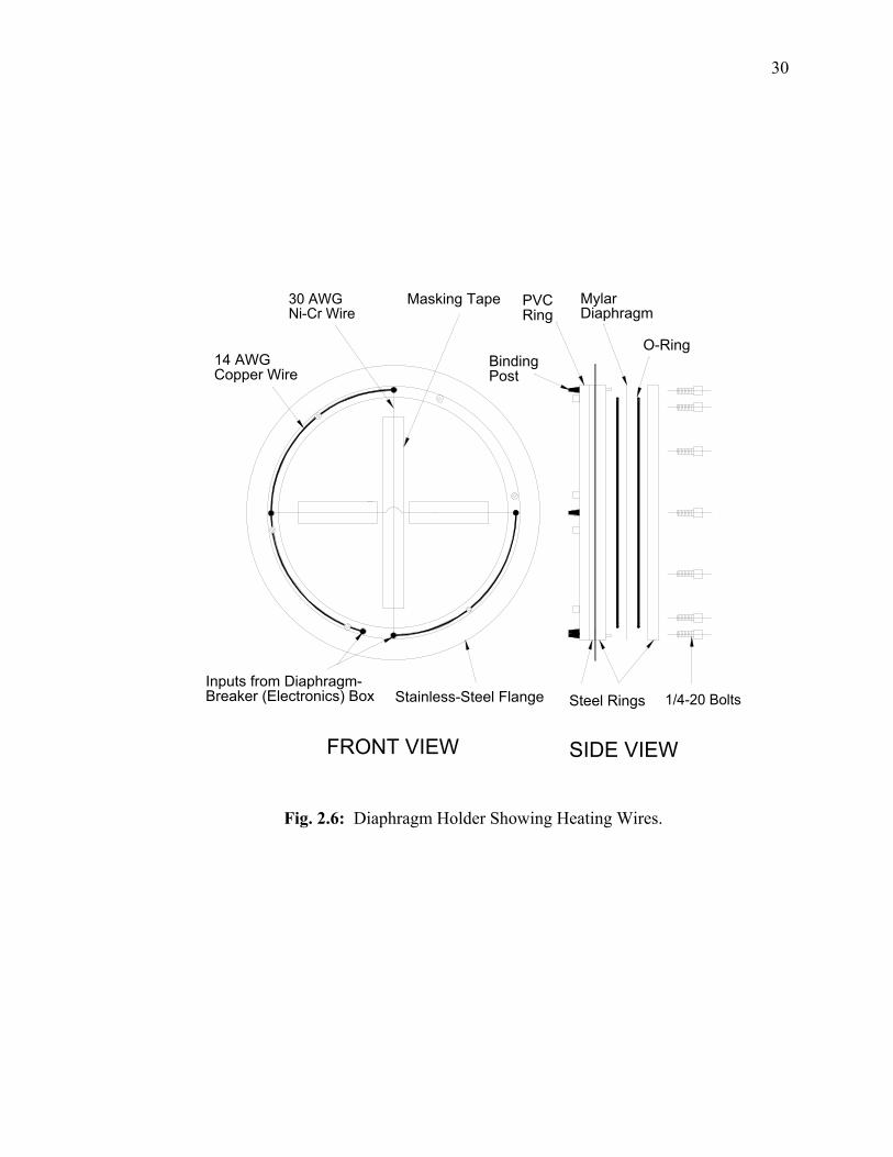
Flow in the PQFLT is started by bursting a 303-mm diameter diaphragm which separates the upstream high-pressure section from the downstream vacuum section. Originally, a double-diaphragm technique was used in which a Mylar diaphragm was clamped and sealed between two flanged sections of the wind tunnel (Schneider and Haven, 1995). As shown in Figure 2.1, each flange is held by a Tube-Turn quick-opening clamp15. In order to start the PQFLT, air was bled into the section separating the two diaphragms until the pressure was large enough to make the diaphragms burst. However, when using Mylar, this technique was problematic in that the diaphragms tended to slip out from between the flanges and rupture prematurely. The problem was that a uniform clamping force was not applied to the outer region of the diaphragm due to misalignment of the flanges. It was found that the diaphragm would slip when gaps as little as 0.12 mm existed between the flanges. In principle, these gaps can be eliminated by proper wind-tunnel alignment. However, the frequent installation and removal of models, probes, and diaphragms makes it difficult to maintain such precise alignment. Consequently, a new burst-diaphragm apparatus was designed to provide a dependable means of starting the PQFLT. The diaphragm holder currently used in the PQFLT is shown in Figure 2.6. Heated wires are used to burst the diaphragm. A 303-mm diameter diaphragm is clamped and sealed between two 12.7-mm thick, precision-machined steel rings by twelve 1/4-20 bolts and two O-rings, respectively. The steel rings are bolted to a 3.8-mm thick stainless-steel ring. Detailed drawings of the diaphragm holder are given in Appendix A. While in the tunnel, the stainless-steel flange is held in place by one of the
15 Manufactured by Tube Turns Inc., Louisville, Kentucky.

16
original Tube-Turns clamps. Consequently, the tunnel flanges are only required to hold and seal the rigid, stainless-steel flange. In this way, the problem of uniformly sealing and clamping the Mylar diaphragm is uncoupled from that of the wind-tunnel alignment. Two 30 AWG Nickel-Chromium (Nichrome) wires are used as heating elements. The wires are connected to binding posts located on the Polyvinyl Chloride (PVC) ring and are fastened to the Mylar by masking tape. The PVC ring electrically isolates the binding posts and wires from the wind-tunnel. The wires are connected in parallel and the combined resistance is on the order of 4.2 Ω. A custom-built electronics box, designed and constructed by Steven P. Schneider, delivers a short pulse of current to the wires. Details on the electronics box are given in Schneider et al. (1996). The resistive heating of the wires melts the Mylar. The diaphragm then petals into quadrants, initiating flow. Two 10 AWG copper wires run from the electronics box to the input binding posts of the diaphragm holder. The electronics box is located outside of the tunnel. A pulse is sent to the Nichrome wires by manually closing a switch. To date, the burst-diaphragm apparatus has been used in hundreds of runs and has proven to be an economical and highly reliable fast-opening device. It takes one person approximately 15 minutes to replace the diaphragm and install the holder in the PQFLT. At present, two diaphragm holders are used such that one may be prepared while the other is in use. The required thickness of the Mylar diaphragm depends on the initial driver tube pressure. In general, single Mylar diaphragms of 0.10 mm (0.004 in), 0.18 mm (0.007 in), and 0.25 mm (0.010 in) thickness are used for driver tube pressure ranges of 50-70 kPa, 70-125 kPa, and 125-170 kPa, respectively. At atmospheric driver tube conditions, a 0.18 mm diaphragm bursts in less than 2 ms Mach-4 flow is established 25 to 40 msec after the diaphragm bursts.
2.2 5o-Cone Model
The 5o-cone model used in this study, shown in Figure 2.7, is made of solid, cold-rolled steel and is 152 mm (6 in) long. The first 145 mm of the model consists of a straight, 5o half-angle cone. The cone smoothly tapers to a 25.4-mm diameter cylinder for the remaining 7 mm of the model. As shown in Figure 2.8, a rounded corner, or shoulder, exists at the intersection of the cone and cylinder cross sections. The radius of the cone tip, or point, is less than 0.006 mm, so bluntness effects are not expected to be a factor. A photograph of the model tip is given in Figure 2.9. The model surface is polished to a rms surface roughness of less than 0.05 µm. Concentric, glow-discharge
26
Second Throat(Fixed Double Wedge)
RectangularDiffuser
Contraction
30.4 cm ø, 20.7 m LongDriver Tube
Test Section
RectangularNozzle
Sliding Sleeve
Tube-Turn Clamps
Burst Diaphragm
To VacuumSystem
Fig. 2.1: The Purdue Quiet-Flow Ludwieg Tube.
Onset of Turbulence inWall Boundary Layer
z
R
Low-NoiseUniform Flow
NonuniformSupersonic Flow
Quiet-FlowTest Core
Noisy FlowRegion
Length of Quiet-Flow Test Core
Lq
MachLines
Optical AccessWindows
Fig. 2.2: Mach 4, Rectangular Nozzle.

27
0.5
0.6
0.7
0.8
0.9
1.0
0 1 2 3 4
Tdo = 298 K
pdo = 89.8 kPa (a)N
orm
aliz
ed P
ress
ure,
p1t
/ p do
0.85
0.90
0.95
1.00
0 1 2 3 4
Tdo = 298 K
pdo = 89.8 kPa
(b)
Time (sec.)
Nor
mal
ized
Tem
pera
ture
, T1t
/ T do
Fig. 2.3: Typical Variation of Stagnation Pressure, p1t, and Temperature, T1t, in the Mach 4, PQFLT. Measurements on Tunnel Centerline and at z = 21.8 cm. (Data Courtesy of J.D. Schmisseur)

28
0.70
0.75
0.80
0.85
1.0 1.2 1.4 1.6 1.8 2.0
(b)
p 1t /
p do
0.60
0.65
0.70
0.75
2.0 2.2 2.4 2.6 2.8 3.0
(c)
Time (sec.)
p 1t /
p do
0.80
0.85
0.90
0.95
0 0.2 0.4 0.6 0.8 1.0
Tdo = 298 K
pdo = 89.8 kPa (a)p 1t
/ p do
Fig. 2.4: Typical Pressure Steps at the Beginning, (a), Near the Middle, (b), and Near the End, (c), of a PQFLT Run.

29
0.89
0.90
0.91
0.92
0.93
0.94
2.0 2.2 2.4 2.6 2.8 3.0
(c)
Time (sec.)
T 1t /
T do
0.92
0.93
0.94
0.95
0.96
0.97
1.0 1.2 1.4 1.6 1.8 2.0
(b)
T 1t /
T do
0.95
0.96
0.97
0.98
0.99
1.00
0 0.2 0.4 0.6 0.8 1.0
Tdo = 298 K
pdo = 89.8 kPa (a)T 1t
/ T do
Fig. 2.5: Typical Temperature Steps at the Beginning, (a), Near the Middle, (b), and Near the End, (c), of a PQFLT Run.
30
Stainless-Steel Flange
Masking Tape
Inputs from Diaphragm-Breaker (Electronics) Box
FRONT VIEW
14 AWGCopper Wire
30 AWGNi-Cr Wire
SIDE VIEW
Steel Rings 1/4-20 Bolts
MylarDiaphragm
PVCRing
BindingPost
O-Ring
Fig. 2.6: Diaphragm Holder Showing Heating Wires.

167
Appendix A: Diaphragm Holder
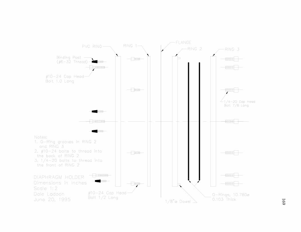
This appendix provides details on the burst-diaphragm apparatus presented in Section 2.1.1. The components and fabrication of the holder are briefly discussed and working, or machine-shop, drawings are given. Although a scale is indicated on the drawings, each has been reduced by 20% in order to fit on a page. An assembly drawing, a list of dimensions, and machine-shop drawings for the diaphragm holder are attached. Referring to the assembly drawing, a 303-mm diameter Mylar diaphragm is clamped and sealed between Rings 2 and 3 by twelve 1/4-20 bolts and two O-rings, respectively. Only Ring 3 is regularly unbolted from the holder. The remaining components are assembled as one permanent unit. The dowels in Rings 2 and 3 allow for easy alignment when the rings are placed together. Holes are punched out of the diaphragm to accommodate the twelve bolts and two dowels. The function of the PVC ring is to electrically isolate the Nichrome heating wires from the earth-grounded wind tunnel. This avoids a ground loop between the electronics of the burst-diaphragm box and the wind tunnel. Binding posts are used for easy installation of the Nichrome wires. The diaphragm holder fits snugly inside the 304-mm diameter tube of the PQFLT. The Flange of the holder is clamped between the flanges of the wind tunnel. A Tube-Turns clamp is tightened over the wind tunnel flanges, which secures the diaphragm holder to the tunnel. The diaphragm holder is assembled as follows. Rings 1 and 2 are fastened to the Flange by six #10-24 bolts. The bolts pass through Ring 1 and the Flange and thread into Ring 2. The surfaces and bolt holes of Rings 1 and 2 are sealed at the Flange with RTV Silicone Rubber. The PVC ring is connected to this combination by six #10-24 bolts that thread into Ring 2. The diaphragms are cut out of a Mylar sheet using an aluminum jig. The position of the dowel and bolt holes are marked on the Mylar with the jig. A paper hole punch is then used to make the holes. The O-rings are custom made from Buna-N rubber stock. Ring 1 is made of cold-rolled steel, the Flange is made of stainless steel, and Rings 2 and 3 are made of tool steel (AISI A2). The faces of Rings 2 and 3 were precision ground to flat surfaces to ensure uniform clamping of the Mylar diaphragm. Rings 2 and 3 were also subjected to a heat treatment process to harden the steel. This is particularly important for Ring 2 in order to prevent stripping of the threaded holes which could result from frequent use. The 1/4-20 bolts connecting Rings 2 and 3 are tightened to a torque of 5.6 N-m using a ratchet-driven torque wrench. This value is sufficient for

168
keeping the diaphragm secure and was determined through experimentation. The maximum outer diameter of Rings 1, 2 and 3 and the PVC ring is set by the inner diameter of the PQFLT. Similarly, the outer diameter of the Flange is limited by the inside diameter of the Tube-Turns clamp. The inside diameter of Rings 2 and 3, and hence the holder, was primarily determined by the bolt-head diameter and the width of the O-ring groove. Since Ring 3 has to be removed and then replaced each time a new diaphragm is installed, it was decided that 1/4-20 socket-head cap screws would be used to give a robust design. However, some structural and aerodynamic concerns are as follows. In terms of minimizing the deflection between the bolts, one wants to have a small-diameter and a thick ring. On the other hand, to reduce wind tunnel blockage, the inner diameter of the ring should be as large as possible. Furthermore, the rings should be thin to prevent the holder from binding when it is inserted in the tunnel. Socket-head cap screws were chosen since they have the smallest head diameter for a given bolt size. This helped keep the inside ring diameter to a reasonably small size. Tests, with the diaphragm holder in the PQFLT, have shown that a Mylar diaphragm significantly deforms under load. For example, the center of a 303-mm diameter, 0.18 mm thick diaphragm deflects by about 27 mm when a pressure difference of 1 atmosphere exists across the diaphragm. In the PQFLT, the Nichrome wires are usually fastened on the upstream, or high pressure, side of the diaphragm, since it is easier to access the binding posts on the PVC ring. In this configuration, the wires are not loaded by the deflected diaphragm just prior to a burst. The wires could also be located on the downstream side of the diaphragm. This may be a preferable configuration, since the deflection of the diaphragm would probably result in better contact between the wires and the Mylar. Obviously, the wires would have to be given some slack so as not to constrain the diaphragm. Minor modifications to the PQFLT would have to be made in order to orient the existing diaphragm holder such that the Nichrome wires would be on the downstream side of the diaphragm. Nevertheless, the existing upstream wire location works well. After the end of a wind tunnel run, the wires are usually left intact and the petaled sections of the diaphragm often remain attached to the holder. Thus, very little debris is blown into the vacuum tank. This is beneficial from a maintenance perspective, since the vacuum tank requires infrequent cleaning.
169

See DETAIL A
170

171

172

See DETAIL C
See DETAIL B
173

See DETAIL D
174

DETAIL A
175

DETAIL B
DETAIL C
176

DETAIL D
177