chapter 2-high speed machining - 123seminarsonly.comespecially in high precision machining and high...
TRANSCRIPT

1
Chapter 2High Speed Machining

2
WHAT IS HIGH SPEED MACHINING (HSM)???
Low Speed High Speed

3
Defined as the use of higher spindle speeds and axis feed rates to achieve high material removal rates without a degradation of part accuracy or quality

4
• The most appropriate definition of high speed machining is based on the workpiece material grade or type

5
• Today the machining center market constitutes at least 60 percent of the total market,.
• Within this market are high-speed machining centers used in small, medium and large batch production.

6
Why HSM ?
• Money: increased productivity and efficiency
• To respond to customers demand for shorter lead times
• Intense competition with low labor cost
Management:
7
• Through HSM, the machining center can reduce the need for polishing.
• It can deliver EDM electrodes more efficiently.
• It can even eliminate EDM in some cases.• Produce complex tooling competitively in a
single setup.
Production:
8
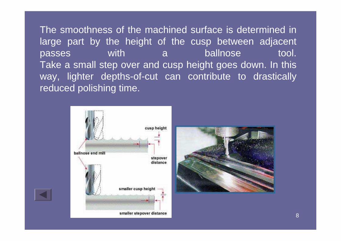
The smoothness of the machined surface is determined in large part by the height of the cusp between adjacent passes with a ballnose tool. Take a small step over and cusp height goes down. In this way, lighter depths-of-cut can contribute to drastically reduced polishing time.

9
There are two cases in which HSM can let the machining center perform effectively in applications where EDM would typically be used:
•Hard milling
•Milling at high L:D ratios

10
• HSM can let milling serve as an alternative to EDM for making dies or molds from the hardest materials (50+ Rc).
Hard Milling
HSM allows a forging supplier to produce dies like this one in a single setup on a machining center, where once a combination of milling and EDM was required. HSM produces the die faster. HSM is also more accurate, because fewer steps result in reduced error stacking.
11
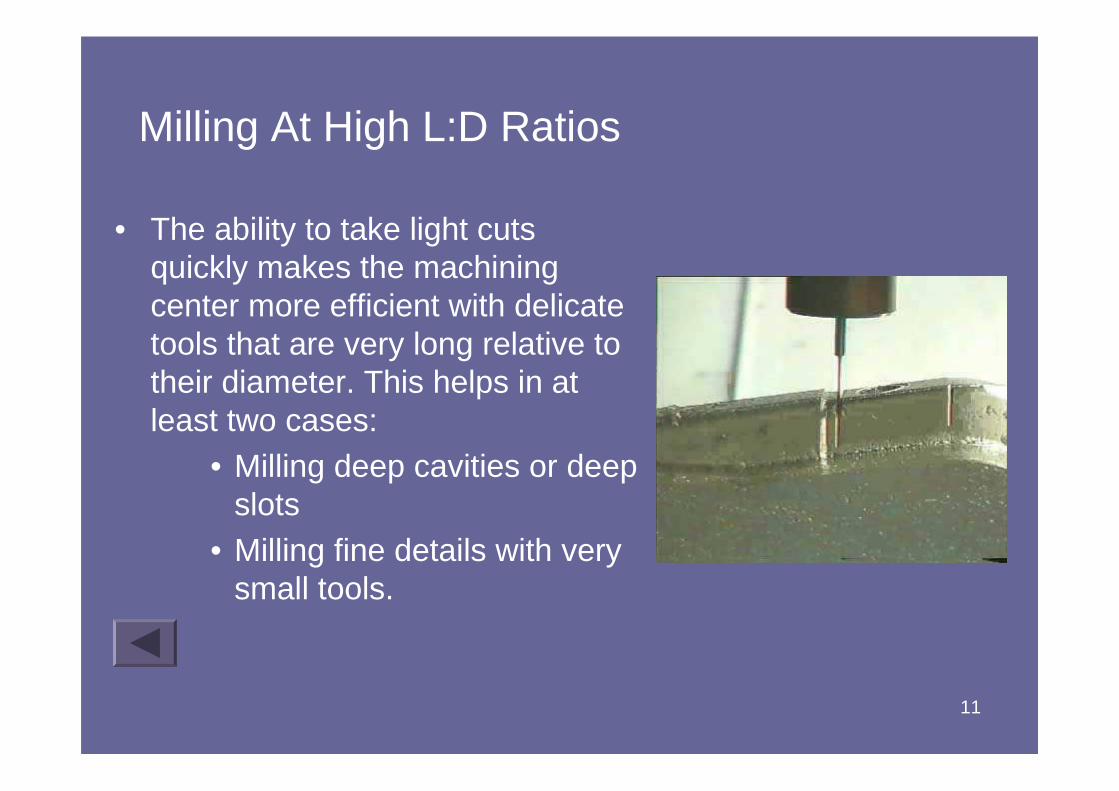
Milling At High L:D Ratios
• The ability to take light cuts quickly makes the machining center more efficient with delicate tools that are very long relative to their diameter. This helps in at least two cases:
• Milling deep cavities or deep slots
• Milling fine details with very small tools.

12
HSM Vs. EDM
• Though HSM expands what milling can do in die/mold machining, EDM still has a role.
• Hardness, geometry, accuracy and finish all determine where HSM and EDM are the most effective.

13
Machine-Tool Structure
• Materials• Machine-tool design consideration

14
• Gray cast iron: – good damping capacity and low cost but very heavy.– made from class 40 and class 50 cast iron.
• Welded steel– Lighter than cast iron structure.– Advantages: available in wide range of sizes and
shapes, desirable mechanical properties, good manufacturing characteristic, low cost, high stiffness to weight ratio, low damping capacity
MATERIAL

15
• Ceramics:– High strength, stiffness, corrosion resistance,
good surface finish and good thermal stability, low density.
• Composite:– Consist of polymer matrix, metal matrix
(MMC), ceramic matrix (CMC).– Can be tailored to obtain appropriate
mechanical properties, suitable for high accuracy and high speed machining.
– However, it is very expensive and limited in use.
MATERIAL

16
• Granite-epoxy composites:– Consisted of 93% crushed granite and 7%
epoxy binder.– Good castability (allows design versatility,
high stiffness to weight ratio, thermal stability, resistance to environment degradation, good damping capacity.
• Polymer concrete:– Mixure of crushed concrete and plastic
(polymethylmethacrylate).
MATERIAL

17
– Can be cast into desired shape and design, good damping capacity, can be used for sandwich construction with cast iron thus improving the mechanical properties.
– Low stiffness (about one-third of class 40 cast iron), poor thermal conductivity.
MATERIAL

18
• A popular method of frame construction for HSM is the bridge-type construction, a modified bridge construction or an overhead gantry system as compared to C-frame by conventional machining center.
• The bridge design provides an optimal distribution of the moving masses and the spindle is rigidly mounted close to the guideways.

19
• A new type of construction so called bridge design in polymer concrete becoming increasingly popular for high-speed machining centers.
• Advantages:• provides excellent accessibility to the working area from the
front for an operator. • The large opening allows good access for a pallet changer or
robot. • The pyramid-shaped construction with three-point support
provides a stiff stationary structure to absorb the high acceleration/deceleration forces of the moving slides.
• provides six to 10 times better vibration dampening than cast iron.
• offers superior thermal stability, as the thermal conductivity of polymer concrete is 1/20 that of cast iron.
• Overall, the results are better tool life, better accuracy and surface quality, plus noise reduction.

20
Machine-Tool Structure and Guideways
An example of a machine-tool structure. The box-type, one-piece design with internal diagonal ribs significantly improves the stiffness of the machine..
Steel guideways integrally-cast on top of the cast-iron bed of a machining center. Because of its higher elastic modulus, the steel provides higher stiffness than cast iron.

21
New monoblock bridge design in polymer concrete.
Assembled machine with integrated pallet changer.
22
Machine-tool design consideration
• Important consideration factors:– Design, materials and construction
– Spindle technology and tool holder– Thermal distortion of machine components
– Error compensation and the motion control of moving components along slideways.

23
• Appropriate material selection, good design and construction are essential especially in high precision machining and high speed machining.
• Role of machine structure is to provide stiffness and, accuracy, thermal stability,good damping, adequate work volume and ease operator access.
Design, materials and construction
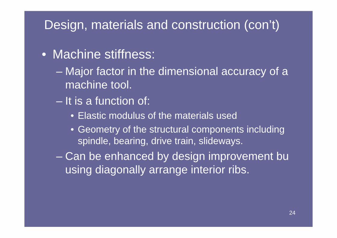
24
• Machine stiffness:– Major factor in the dimensional accuracy of a
machine tool. – It is a function of:
• Elastic modulus of the materials used• Geometry of the structural components including
spindle, bearing, drive train, slideways.
– Can be enhanced by design improvement buusing diagonally arrange interior ribs.
Design, materials and construction (con’t)

25
Static stiffness
• Measured in unit of N/mm
• Measured the resistance of a body to deflection under load.
• Simple example is the embodiment of static stiffness is a linear spring.
• Stiffness of machine tool structure is closely related to machine tool capability, will affects the accuracy and the extent to which the machine can support high feed rates and accelerations.
26
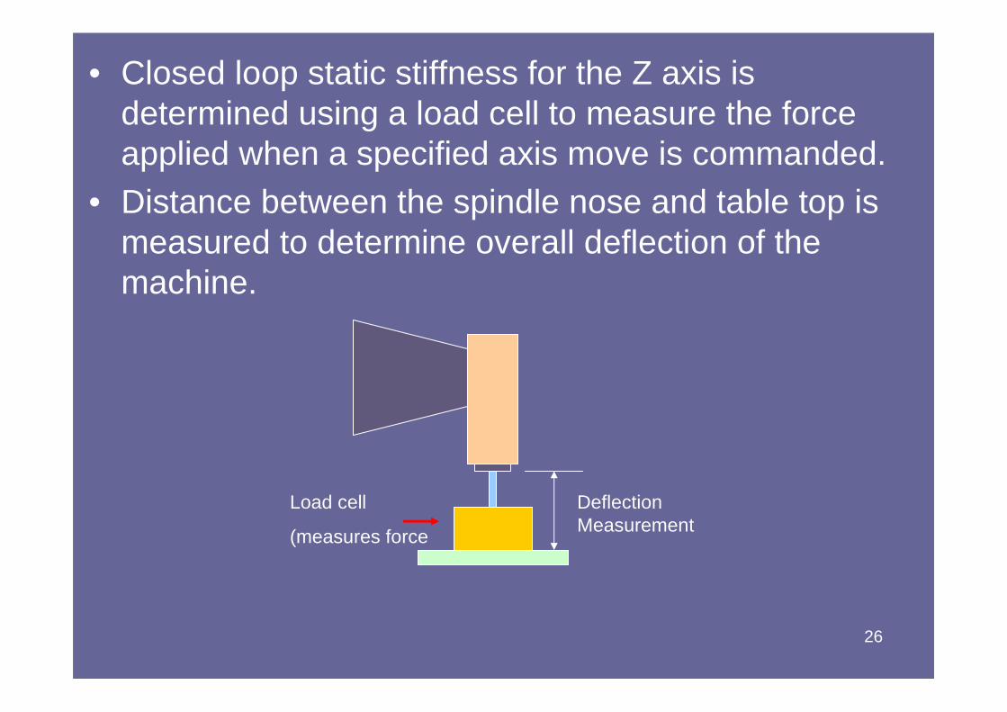
• Closed loop static stiffness for the Z axis is determined using a load cell to measure the force applied when a specified axis move is commanded.
• Distance between the spindle nose and table top is measured to determine overall deflection of the machine.
Load cell
(measures force
Deflection Measurement

27
• Open loop static stiffness of the Z axis is measured by applying a known force to the Z axis spindle and measuring its deflection.
• Only the stiffness of the drive train, slide and column is measured.
Deflection Measurement
Known force applied
F
28
Dynamic stiffness
• Lower than static stiffness and varies infrequency.
• Resonant frequency is a frequency at which vibration is not adequately damped, thereby affecting controllability of the system, surface finish and accuracy.

29
• Damping:– Very critical factor in reducing or eliminating vibration
and chatter in machining operations. – Involves:
• Type of materials used• Type of joints• Number of joints (welded, bolted)
– Greater the number of joints the more the damping.– Well damped machine tools provide better surface
finish and support high accelerations and feed rates because more control algorithms can be used.
Design, materials and construction (con’t)

30
Internal Damping of Structural Materials
The relative damping capacity of (a) gray cast iron and (b) epoxy-granite composite material. The vertical scale is the amplitude of vibration and the horizontal scale is time.

31
Joints in Machine-Tool Structures
The damping of vibrations as a function of the number of components on a lathe. Joints dissipate energy; the greater the number of joints, the higher the damping capacity of the machine.

32
Spindle Technology
• High speed spindle design must provide required performance features include:– Desired spindle power
– Max spindle load, axial and radial– Max spindle speed allowed
– tooling style, size and capacity for ATC– Belt driven or integral motor-spindle design

33
Major design components required:
a) Belt driven – Assembly consists of spindle shaft, held with
bearing system and supported by the spindle housing.
– Spindle shaft incorporates the tooling system including the tool taper, drawbar mechanism and tool release system.
– Motor is mounted adjacent to the spindle and the torque is transmitted to the spindle by cogged or V-belt.
1) Spindle style:

34
35
• Advantages of belt driven:– Reasonable cost
– Wide variety of spindle characteristic– High power and torque possible
• Limitations:– Max speed is limited
– Belt utilize bearing load capacity
Major design components required (con’t):

36
b) Integral motor –spindle design– Does not rely upon the external motor to
provide torque and power.– Include an integral part of the spindle shaft
and housing assy which higher spindle speed rotation.
– Comprised of spindle shaft, including motor element and tooling system.
– Spindle shaft is held in position by a set of precision bearings.
Major design components required (con’t):

37
Major design components required (con’t):

38
2) Spindle bearings
• Bearing type must be fulfill these requirements:– High rotational speed
– transfer torque and power to the cutting tool– capable to reasonable loading and life.
Major design components required (con’t):

39
Major design components required (con’t):
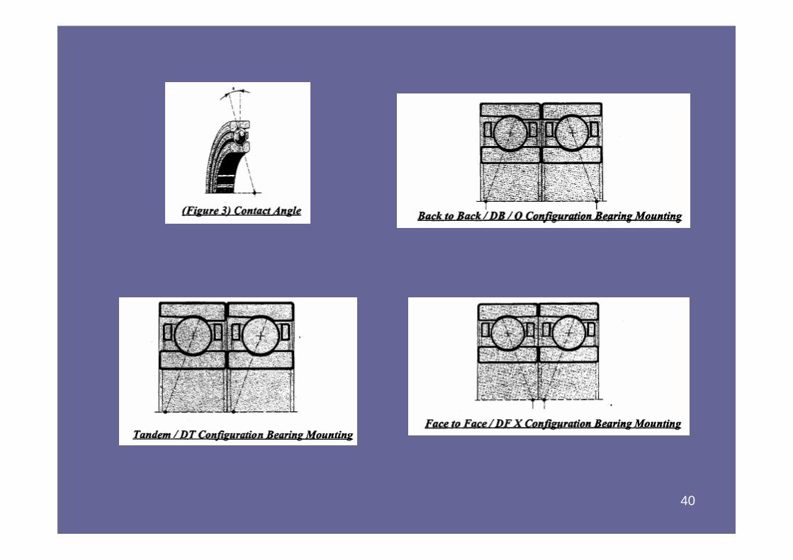
40

41
• Most common used is an AC induction motor.• Rotor is attached to the spindle shaft with
thermal or adhesive clamping.
3) Spindle motor design
Major design components required (con’t):

42
• The bearings are mounted to the front and rear of the shaft and the shaft is then fitted into the spindle housing.
• Spindle shaft must capable to transfer the power from the motor to the cutting tool avoid from bending.
Major design components required (con’t):
4) Spindle shaft
43
• Spindle housing shaft and motor for HSM is held in a cartridge type housing.
• Primary function:– Locate the bearings– Provide the lubrication, air seal, cooling water
or oil.
5) Spindle housing
Major design components required (con’t):

44

45
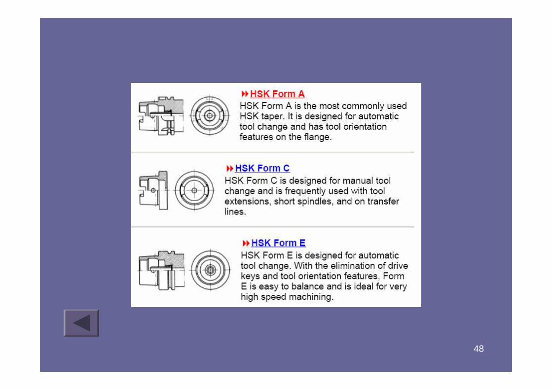
Tool holder
• Common type: BT40, CAT 40 and ISO 30• CAT 40 up to 20,000 rpm• At higher speeds, spindle taper expands more than
cutting tool causing:– Axial position changes– Tool may bind in spindle
• Current trend: HSK (Hollow Shank Taper) tool holder– German DIN69893 & DIN69063– Better axial positioning– Will not bind in spindle– Faster tool change– Shorter length– Lower mass– Require more attention to cleanliness

46

47
48
49
Thermal distortion
• 50% of machine-tool errors and accuracy are due to temperature.
• Methods of heat transfer:– Conduction– Convection– Radiation
• Source:– Internal: from bearing, ballscrew, machine ways,
spindle motor, pumps etc– External: cutting fluid, sunlight, ambient temperature
etc

50
• Solutions:– Thermal and geometric real-time error
compensating features was implemented for accurate ballscrew positions.
– Gas or fluid hydrostatic spindle bearings.
– New design for traction or friction drives for linear motion.
– Extremely fine feed and position controls using microactuators
– Fluid circulation channels in the machine-tool base for the maintenance of thermal stability.

51

52

53

54

55

56

57

58

59

60

61
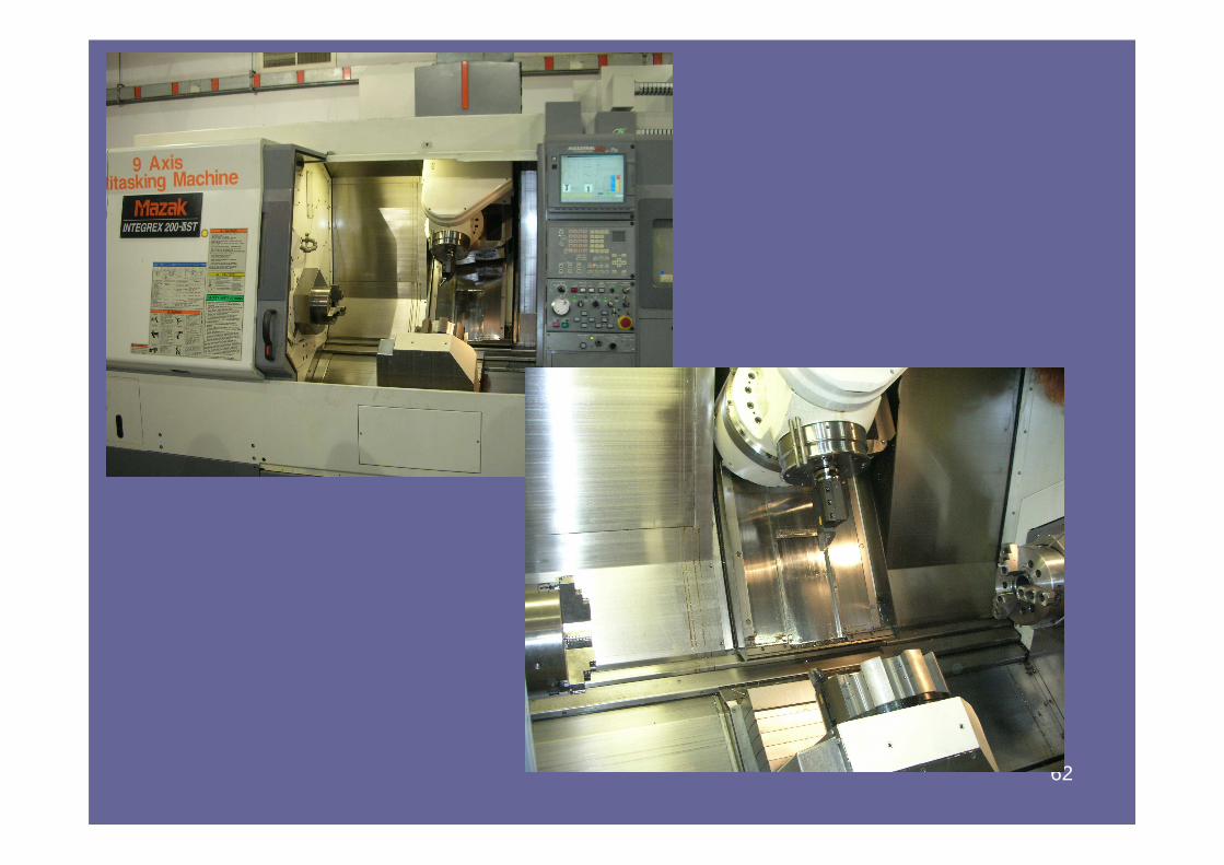
62
63

64
Video presentation
Video #1
Video #2
Video #3
Video #4