chapter 2 modeling data in the...
TRANSCRIPT

Chapter 2
Copyright © 2014 Pearson Education, Inc.
17
Chapter 2 Modeling Data in the Organization
Chapter Overview
The purpose of this chapter is to present a detailed description of the entity-relationship model
and the use of this tool within the context of conceptual data modeling. This chapter presents the
basic entity-relationship (or E-R) model. Advanced features of conceptual data modeling will
follow in Chapter 3.
Chapter Objectives
Specific student learning objectives are included in the beginning of the chapter. From an
instructor’s point of view, the objectives of this chapter are to:
1. Emphasize the importance of understanding organizational data, and convince your
students that unless they can represent data unambiguously at the conceptual level, they
cannot implement a database that will effectively serve the needs of various
organizational stakeholder groups.
2. Present the E-R model as a conceptual data model that can be used to capture the
structure and much, although not all, of the semantics (or meaning) of data.
3. Apply E-R modeling concepts to several practical examples including the Pine Valley
Furniture Company case.
Key Terms
Associative entity Entity type Optional attribute
Attribute Entity-relationship diagram
(E-R diagram)
Relationship instance
Binary relationship Relationship type
Business rule Entity-relationship model
(E-R model)
Required attribute
Cardinality constraint Simple (or atomic) attribute
Composite attribute Identifier Strong entity type
Composite identifier Identifying owner Ternary relationship
Degree Identifying relationship Time stamp
Derived attribute Maximum cardinality Unary relationship
Entity Minimum cardinality Weak entity type
Entity instance Multivalued attribute
Classroom Ideas
1. Review the major steps in the database development process (Figures 1-7 and 1-8) and
highlight the importance of data modeling in determining the overall data requirements of
information systems. Lead a discussion regarding the parties within an organization that
typically are most heavily involved in each of the steps and how end users may best
participate in the process.
2. Introduce the concept of drawing models to represent information in a concise manner by
having your students participate in a small active exercise in map-making. Divide the

Essentials of Database Management, First Edition
Copyright © 2014 Pearson Education, Inc.
18
students into teams of 3 – 4 each so that you have an even number of teams in the class.
Instruct each team to work together to investigate and develop a map to selected campus
locations (you develop the list ahead of time; e.g., from this classroom to the library, from
this classroom to a colleague’s office, etc.). Ask each team to verify the map they draw
and then return to the classroom. Pair up each team with a unique location with another
team; ask the teams to exchange maps. Instruct each team to then verify the map they
received by following it and then returning to the classroom. Conduct a debriefing
discussion about how easy/hard it was to follow the maps, how useful were the symbols
used, how easily understood were the symbols, etc. Use this discussion to lead into the
use of E-R notation used to represent data models and why standardization is useful to
systems development activities.
3. Use the sample E-R diagram shown in Figure 2-1 to introduce the first conceptual model
to your students. Ask them to explain the business rules represented in this diagram.
4. Use Figure 2-2 to summarize the basic E-R notation used in this chapter and throughout
the remainder of the text.
5. Contrast the terms entity type and entity instance (see Figure 2-3). Discuss other
examples: STUDENT with each student in the classroom as an instance, etc. Warn the
students that the term “entity” is often used either way; the meaning is intended to come
from the context in which it is used.
6. Give examples of common errors in E-R diagramming, including inappropriate entities
(see Figure 2-4). Ask your students for other examples.
7. Compare strong versus weak entities using Figure 2-5. Ask your students for other
examples.
8. Discuss the various types of attributes that are commonly encountered (Figures 2-7
through 2-9). Again, ask your students to think of other examples.
9. Make sure your students understand the difference between relationship types and
relationship instances (Figure 2-10).
10. Introduce the notion of an associative entity by using Figure 2-11. Discuss the four
reasons (presented in the text) for converting a relationship to an associative entity.
11. Discuss unary, binary, and ternary relationships (Figure 2-12). Have the students
brainstorm at least two additional examples for each of these relationship degrees.
12. Discuss the bill-of-materials unary relationship (Figure 2-13). Use a simple and familiar
product (such as a toy) to illustrate this essential structure, which is often difficult for
students to understand.
13. Introduce the concept and notation of cardinality constraints in relationships (Figures 2-
16, 2-17, and 2-18). Emphasize that these constraints are important expressions of
business rules.
14. Introduce the problem of representing time dependent data. Use Figure 2-19 to illustrate
one technique for coping with time dependencies.
15. Discuss examples of multiple relationships between entities (Figure 2-20). Ask your
students to suggest other examples.
16. Use the diagram for Pine Valley Furniture Company (Figure 2-21) to illustrate a more
comprehensive E-R diagram. Stress that in real-world situations, E-R diagrams are often
much more complex than this example.
17. As time permits, have your students work in small teams, 2 or 3 students each, to solve

Chapter 2
Copyright © 2014 Pearson Education, Inc.
19
some of the E-R diagramming tasks in the Problems and Exercises section of the chapter.
Answers to Review Questions
1. Define each of the following terms:
a. Entity type. A collection of entities that share common properties or
characteristics
b. Entity-relationship model. A logical representation of the data for an organization
or for a business area
c. Entity instance. A single occurrence of an entity type
d. Attribute. A property or characteristic of an entity type that is of interest to the
organization
e. Relationship type. A meaningful association between (or among) entity types
f. Identifier. An attribute (or combination of attributes) that uniquely identifies
individual instances of an entity type
g. Multivalued attribute. An attribute that may take on more than one value for a
given entity instance
h. Associative entity. An entity type that associates the instances of one or more
entity types and contains attributes that are peculiar to the relationship between
those entity instances
i. Cardinality constraint. Specifies the number of instances of one entity that can (or
must) be associated with each instance of another entity
j. Weak entity. An entity type whose existence depends on some other entity type
k. Identifying relationship. The relationship between a weak entity type and its
owner
l. Derived attribute. An attribute whose values can be calculated from related
attribute values
m. Business rule. A statement that defines or constrains some aspect of the business
2. Match the following terms and definitions:
i composite attribute
d associative entity
b unary relationship
j weak entity
h attribute
m entity
e relationship type
c cardinality constraint
g degree
a identifier
f entity type
k ternary
l bill-of-materials
Essentials of Database Management, First Edition
Copyright © 2014 Pearson Education, Inc.
20
3. Contrast the following terms:
a. Stored attribute; derived attribute. A stored attribute is one whose values are
stored in the database, while a derived attribute is one whose values can be
calculated or derived from related stored attributes.
b. Simple attribute; composite attribute. A simple attribute is one that cannot be
broken down into smaller components, while a composite attribute can be broken
down into component parts.
c. Entity type; relationship type. An entity type is a collection of entity instances that
share common properties or characteristics, while a relationship type is a
meaningful association between (or among) entity types.
d. Strong entity type; weak entity type. A strong entity type is an entity that exists
independently of other entity types, while a weak entity type depends on some
other entity type.
e. Degree; cardinality. The degree (of a relationship) is the number of entity types
that participate in that relationship, while cardinality is a constraint on the number
of instances of one entity that can (or must) be associated with each instance of
another entity.
f. Required attribute; optional attribute. A required attribute must have a value for
each entity instance, whereas an optional attribute may not have a value for every
entity instance.
g. Composite attribute; multivalued attribute. A composite attribute has component
parts that give meaning, whereas a multivalued attribute may take one or more
values for an entity instance.
h. Ternary relationship; three binary relationships. A ternary relationship is a
simultaneous relationship among the instances of three entity types and often
includes attributes unique to that simultaneous relationship. Three binary
relationships reflect the three two-way relationships between two entity types, and
do not depict the same meaning as a ternary relationship.
4. Three reasons underlying the importance of data modeling:
a. The characteristics of data captured during data modeling are crucial in the design
of databases, programs, and other system components. Facts and rules that are
captured during this process are essential in assuring data integrity in an
information system.
b. Data, rather than processes, are the most important aspects of many modern
information systems and hence, require a central role in structuring system
requirements.
c. Data tend to be more stable than the business processes that use the data. Thus, an
information system that is based on a data orientation should have a longer useful
life than one based on a process orientation.
5. Where can you find business rules? Business rules appear in descriptions of business
functions, events, policies, units, stakeholders, and other objects. These descriptions can
be found in interview notes from individual and group information systems requirements
collection sessions, organizational documents, and other sources. Rules are identified by

Chapter 2
Copyright © 2014 Pearson Education, Inc.
21
asking questions about the who, what, when, where, why, and how of the organization.
6. Six general guidelines:
a. Data names should relate to business, not technical characteristics.
b. Data names should be meaningful, almost to the point of being self-documenting.
c. Data names should be unique from the name used for every other distinct data
object.
d. Data names should be readable. The names should be structured in a way
consistent with how the concepts would most naturally be said.
e. Data names should be composed of words taken from an approved list.
f. Data names should be repeatable, meaning that different people or the same
person at different times should develop exactly or almost the same name.
7. Four criteria:
a. Choose an identifier that will not change its value over the life of each instance of
the entity type.
b. Choose an identifier such that for each instance of the entity the attribute is
guaranteed to have valid values and not be null (or unknown).
c. Avoid the use of so-called intelligent identifiers (or keys), whose structure
indicates classifications, locations, and so on.
d. Consider substituting single-attribute surrogate identifiers for large composite
identifiers.
8. Why composite rather than simple?
An identifier attribute is an attribute (or combination of attributes) whose value
distinguishes individual instances of an entity type. Often, a simple attribute will not be
unique for all instances of an entity type (e.g., FlightNumber for an instance of an airline
flight). Rather, a combination of simple attributes will be needed to uniquely identify the
entity instance (e.g., FlightID and FlightDate would make the instance unique).
9. Three conditions for an associative entity type:
a. All of the relationships for the participating entity types are “many” relationships.
b. The resulting associative entity type has independent meaning to end users, and it
preferably can be identified with a single-attribute identifier.
c. The associative entity has one or more attributes in addition to the identifier.
10. Four types of cardinality constraints:
a. Optional one:

Essentials of Database Management, First Edition
Copyright © 2014 Pearson Education, Inc.
22
b. Mandatory one:
c. Optional many:
d. Mandatory many:
11. Example of weak entity: Phone Call (see below) is an example of a weak entity because a
phone call must be placed by a PERSON and thus, an instance of PHONE CALL cannot
exist without an instance of PERSON. In this simple example, PHONE CALL is related
to only one other entity type, Thus, it is not necessary to show the identifying
relationship; however, if this data model were ever expanded so that PHONE CALL
related to other entity types, it is good practice to always indicate the identifying
relationship.
12. Degree of relationship definition & examples:
The degree of a relationship is the number of entity types that participate in the
relationship.
a) Unary (one entity type):

Chapter 2
Copyright © 2014 Pearson Education, Inc.
23
b) Binary (two entity types):
c) Ternary (three entity types):
13. Attribute examples:
a. Derived – distance (rate x time); both rate and time could be stored, and then
when the data is retrieved from the database (e.g., at run-time) the distance could
be calculated from the already-stored data elements
b. Multivalued – spoken language; a person can speak more than one language
c. Atomic – Social Security Number; this United States National Identification
number cannot be broken down into component parts
d. Composite – Phone Number; a phone number is often broken down into country
code, area code, and the rest of the phone number
e. Required – First Name or Last Name of a person; although Middle Initial may be
optional, a person’s First Name and Last Name are generally necessary for
business records in a database so the person can be appropriately addressed
f. Optional – Middle Initial; a person’s middle initial may be optional for
identification purposes or also because some people may not have a middle name
14. Examples of relationships:
(a) Ternary

Essentials of Database Management, First Edition
Copyright © 2014 Pearson Education, Inc.
24
The sale of a property is a simultaneous relationship among the PROPERTY, a BUYER, and an
OWNER entity types. This “event” cannot be modeled appropriately with three binary
relationships; any one of the three binary relationships (PROPERTY-BUYER; BUYER-
OWNER; and PROPERTY-OWNER) is missing an essential element of the sale.
(b) Unary
In an on-campus dormitory/apartment situation, this diagram shows a recursive/unary
relationship among instances of the STUDENT entity type. This notation indicates only
the current roommate situation between instances of the STUDENT entity type.
15. Effective (or effectivity) dates:
Effective (or effectivity) dates are used in a data model when the organization wishes to
record historical data, rather than just the current instance. A few examples might include
the effective date of a product price or service rate. Another example might be the start
and end date of an advisor’s assignment to work with a student at a university (see E-R
segment below, which includes a multivalued composite attribute Advisor).
16. Special guidelines for naming relationships:
A relationship name should always be a verb phrase and should state the action taken,

Chapter 2
Copyright © 2014 Pearson Education, Inc.
25
as opposed to the result of the action taken.
Use descriptive, powerful verb phrases as opposed to vague names.
17. The relationship definition should also explain the following:
any optional participation
the reason for any explicit maximum cardinality
any mutually exclusive relationships
any restrictions on participation in the relationship
the extent of history that is kept in the relationship
whether an entity instance involved in a relationship instance can transfer partici-
pation to another relationship instance
18. Manages relationship in Figure 12a:
Presently, the cardinality is one-to-many. One possible scenario is an employee who is
supervised by more than one manager. This would make the cardinality many-to-many.
Another possibility (although very rare in practice) is that the employee is supervised by
one manager, and the manager only supervises one employee. This would result in a one-
to-one cardinality. If we take time/history into consideration, the idea of someone being
managed currently versus never being managed could affect the cardinality. As we can
see here, you cannot always tell what the business rule is by looking at the ERD. These
possible scenarios will need to be discussed with the end user to determine the “correct”
modeling representation for the business rules at this organization.
19. Entity type vs. Entity instance:
An entity type can be thought of as a template, defining all of the characteristics of an
entity instance. For example, “student” would be an entity type, whereas you are an
instance of “student.”
20. Conversion of ternary relationship into an associative entity:
Converting a ternary relationship into an associative entity is recommended for two main
reasons: (1) research has shown that participation/cardinality constraints cannot be
accurately represented for a ternary relationship with current notation; and (2) most E-R
diagramming tools cannot represent ternary relationships. By converting a ternary
relationship into an associative entity with three mandatory binary relationships, a data
modeler can accurately represent the participation/cardinality constraints although there is
a risk that the meaning/semantics of the original ternary relationship is lost with this
solution.

Essentials of Database Management, First Edition
Copyright © 2014 Pearson Education, Inc.
26
Answers to Problems and Exercises
1. Cellular Operator Database Figure 2-23 questions:
a. Can a customer have an unlimited number of plans?
Yes. A Customer may be responsible for 0, 1, or many Plans.
b. Can a customer exist without a plan?
Yes. The minimum cardinality of the Belongs relationship from the Customer to the Plan
states that a Customer may exist without a Plan (the minimum cardinality is 0).
c. Is it possible to create a plan without knowing who the customer is?
No. The minimum cardinality of both the “responsible for” and “belongs” relationships
between Plan and Customer states that at least one Customer must be related to a Plan.
d. Does the operator want to limit the types of handsets that can be linked to a specific plan
type?
Yes, the cellular operator requires that a Handset (that is a particular type and a particular
operating system) is linked to one Plan (that is a particular type of plan). This business
rule is to be implemented in this design by indirectly requiring that a Plan Type has 0:M
Plans, and each Plan is associated with certain Handsets, and each Handset is of some
Handset Type. A given Plan Type is related to Handset Type through the intermediary
entity types in this design.
e. Is it possible to maintain data regarding a handset without connecting it to a plan?
Yes. The minimum cardinality of the Includes relationship between Plan and Handset
states that a Handset may be included in 0 or 1 plan. The 0 minimum cardinality means
that we can track data about the handset even if it is not connected to a plan; the Handset
has optional participation in the Includes relationship with Plan.
f. Can a handset be associated with multiple plans?
No. The minimum cardinality of the Includes relationship between Plan and Handset
states that a Handset may be included in 0 or 1 plan, not multiple plans.
g. Assume a handset type exists that can utilize multiple operating systems. Could this
situation be accommodated within the model included in Figure 2-23?
No. The current model shows that a handset type is associated with one and only one
operating system.

Chapter 2
Copyright © 2014 Pearson Education, Inc.
27
h. Is the company able to track a manufacturer without maintaining information about its
handsets?
Yes. The minimum cardinality of the relationship between Manufacturer and Handset
Type indicates that we can track data about a Manufacturer even if we have no (or zero)
Handset Types in our database.
i. Can the same operating system be used on multiple handset types?
Yes. The maximum cardinality on the relationship between Operating System and
Handset Type indicates that an Operating System may be used on 0, 1, or many Handset
types.
j. There are two relationships between Customer and Plan. Explain how they differ.
The Responsible For relationship is an overall 1:M relationship between Customer and
Plan. A Customer can be responsible for 0, 1, or many Plans yet any one Plan will be
linked to only 1 Customer for responsibility purposes. The Belongs relationship is an
overall M:M relationship that permits the linking of multiple customers to a single plan,
as in the case of family members being part of a particular plan or different plans.
k. Characterize the degree and the cardinalities of the relationship that connects Customer to
itself. Explain its meaning.
The “Family Member” relationship that connects Customer to itself has a degree of 1
(unary). It permits the tracking of each family member as a Customer. Any Customer
may be a Family Member of 0, 1, or many Customer(s); as a Family Member Customer,
the Customer may be linked to 0 or 1 Customer.
l. Is it possible to link a handset to a specific customer in a plan with multiple customers?
No, this is not possible according to the current model. However, the current model
could be adjusted to create an Associative Entity to track the particular Customer instance
with a particular Plan instance that is then associated with a particular Handset. This
suggested extension to the current model also permits a design that will easily extend the
database’s ability to track additional data about the particular Customer instance with a
particular Plan instance.
m. Can the company track a handset without identifying its operating system?
No. The minimum cardinality of the relationship between Handset Type and Operating
System is 1 and only 1; the minimum of 1 is a mandatory participation for the Handset
Type with the Operating System.
2. For each of the descriptions below, perform the following tasks:

Essentials of Database Management, First Edition
Copyright © 2014 Pearson Education, Inc.
28
i) Identify the degree and cardinalities of the relationship.
ii) Express the relationships in each description graphically with an E-R diagram
a. A book is identified by its ISBN (International Standard Book Number), and it has a title,
a price, and a date of publication. It is published by a publisher, each of which has its own
ID number and a name. Each book has exactly one publisher, but one publisher typically
publishes multiple books over time.
(2.a.i) This relationship is a degree of 2 (binary). This relationship is one-to-many from
Publisher to Book.
(2.a.ii)
Note: This solution assumes that we have a reason to track a Publisher even if it does not
yet have a Book published.
b. A book (see above in 2.a) is written by one or multiple authors. Each author is identified
by an author number and has a name and date of birth. Each author has either one or
multiple books; in addition, occasionally data are needed also regarding prospective
authors who have not yet published any books.
(2.b.i) This relationship is a degree of 2 (binary). This relationship is many-to-many
from Author to Book.
(2.b.ii)
c. In the context specified above in 2.a and 2.b, better information is needed regarding the
relationship between a book and its authors. Specifically, it is important to record the
percentage of the royalties that belong to a specific author, whether or not a specific
author is a lead author of the book, and each author’s position in the sequence of the
book’s authors.
(2.c.i) This relationship is a degree of 2 (binary). This relationship is many-to-many
from Author to Book.

Chapter 2
Copyright © 2014 Pearson Education, Inc.
29
(2.c.ii)
d. A book (see 2.a above) can be part of a series, which is also identified as a book and has
its own ISBN number. One book can belong to several sets, and a set consists of at least
one but potentially many books.
(2.d.i) This relationship is a degree of 1 (unary). This relationship is many-to-many.
(2.d.ii) This solution assumes that “series” and “sets” are synonymous terms. The
question does not require that a series have any special attributes or distinguishing
features, so it can be represented in the data model like any other Book instance and
identified by ISBN.
e. A piano manufacturer wants to keep track of all the pianos it makes individually. Each
piano has an identifying serial number and a manufacturing completion date. Each
instrument represents exactly one piano model, all of which have an identification
number and a name. In addition, the company wants to maintain information about the
designer of the model. Over time, the company often manufactures thousands of pianos
of a certain model, and the model design is specified before any single piano exists.
(2.e.i) These relationships have a degree of 2 (binary). These relationships are one-to-
many.

Essentials of Database Management, First Edition
Copyright © 2014 Pearson Education, Inc.
30
(2.e.ii)
f. A piano manufacturer (see 2.e above) employs piano technicians who are responsible for
inspecting the instruments before they are shipped to the customers. Each piano is
inspected by at least two technicians (identified by their employee number). For each
separate inspection, the company needs to record its date and a quality evaluation grade.
(2.f.i) This relationship is a degree of 2 (binary). This relationship is many-to-many.
(2.f.ii)
g. The piano technicians (see 2.f above) have a hierarchy of reporting relationships: some of
them have supervisory responsibilities in addition to their inspection role and have
multiple other technicians report to them. The supervisors themselves report to the chief
technician of the company.
(2.g.i) This relationship is a degree of 1 (unary). This relationship is one-to-many.
(2.g.ii) Because the chief technician is not represented as a separate entity type, that
person does not have a supervisor. This, in turn, leads to the 0 minimum cardinality on
the 1 side of the unary relationship.

Chapter 2
Copyright © 2014 Pearson Education, Inc.
31
h. A vendor builds multiple types of tablet computers. Each type has a type identification
number and a name. The key specifications for each type include amount of storage space
and display type. The company uses multiple processor types, exactly one of which is
used for a specific tablet computer type; obviously, the same processor can be used in
multiple types of tablets. Each processor has a manufacturer and a manufacturer’s unique
code that identifies it.
(2.h.i) This relationship is a degree of 2 (binary). This relationship is many-to-many.
(2.h.ii)
i. Each individual tablet computer manufactured by the vendor (see 2.h above) is identified
by the type identification number and a serial number that is unique within the type
identification. The vendor wants to maintain information about when each tablet is
shipped to a customer.
(2.i.i) These relationships are a degree of 2 (binary). These relationships are one-to-
many. If, over time, shipment of a tablet computer to multiple customers (e.g., as in a
refurbished unit) is possible, the Tablet Computer – Customer relationship would become
many-to-many and the Shipping Date attribute would become an attribute of that M:N
relationship.
(2.i.ii)
j. Each of the tablet computer types (see 2.h above) has a specific operating system. Each
technician the company employs is certified to assemble a specific tablet type – operating
system combination. The validity of a certification starts on the day the employee passes a
certification examination for the combination, and the certification is valid for a specific
period of time that varies depending on tablet type–operating system combination.
(2.j.i) This relationship is a degree of 2 (binary). This relationship is many-to-many.
Essentials of Database Management, First Edition
Copyright © 2014 Pearson Education, Inc.
32
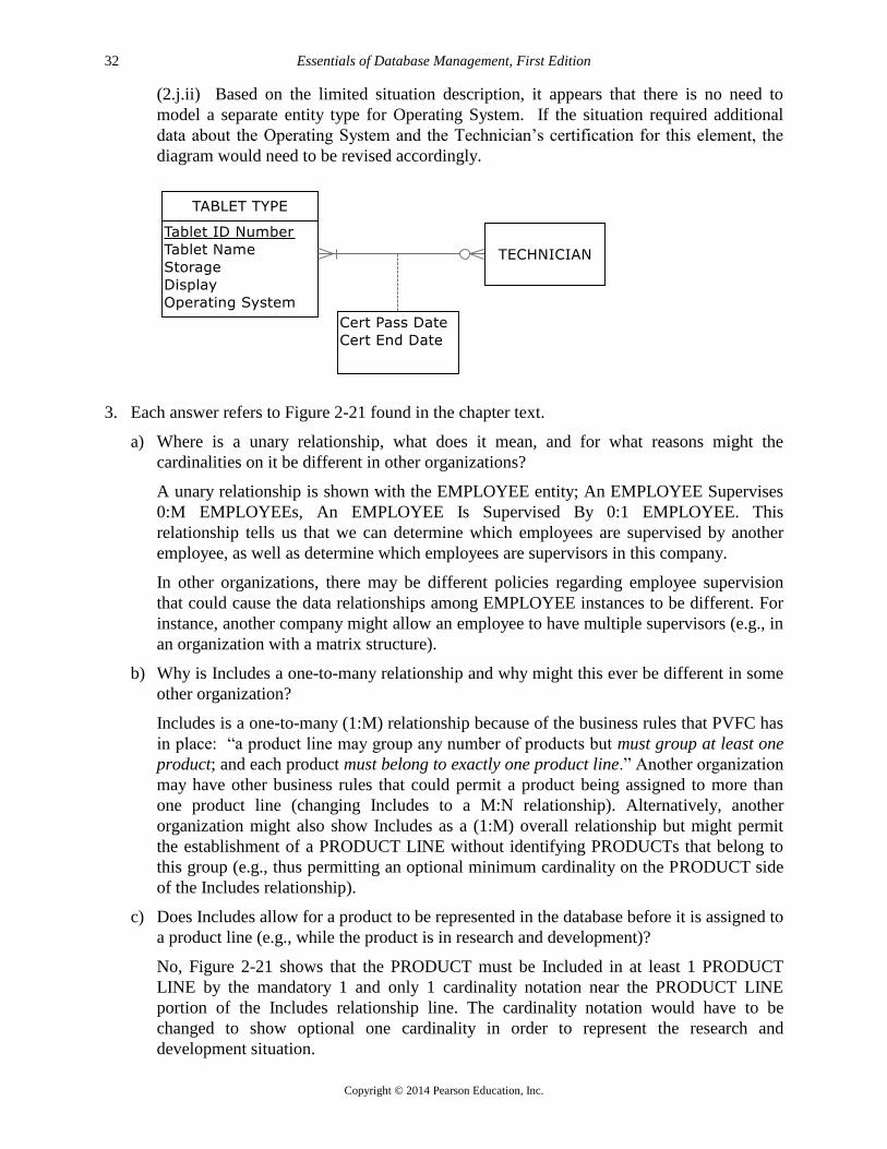
(2.j.ii) Based on the limited situation description, it appears that there is no need to
model a separate entity type for Operating System. If the situation required additional
data about the Operating System and the Technician’s certification for this element, the
diagram would need to be revised accordingly.
3. Each answer refers to Figure 2-21 found in the chapter text.
a) Where is a unary relationship, what does it mean, and for what reasons might the
cardinalities on it be different in other organizations?
A unary relationship is shown with the EMPLOYEE entity; An EMPLOYEE Supervises
0:M EMPLOYEEs, An EMPLOYEE Is Supervised By 0:1 EMPLOYEE. This
relationship tells us that we can determine which employees are supervised by another
employee, as well as determine which employees are supervisors in this company.
In other organizations, there may be different policies regarding employee supervision
that could cause the data relationships among EMPLOYEE instances to be different. For
instance, another company might allow an employee to have multiple supervisors (e.g., in
an organization with a matrix structure).
b) Why is Includes a one-to-many relationship and why might this ever be different in some
other organization?
Includes is a one-to-many (1:M) relationship because of the business rules that PVFC has
in place: “a product line may group any number of products but must group at least one
product; and each product must belong to exactly one product line.” Another organization
may have other business rules that could permit a product being assigned to more than
one product line (changing Includes to a M:N relationship). Alternatively, another
organization might also show Includes as a (1:M) overall relationship but might permit
the establishment of a PRODUCT LINE without identifying PRODUCTs that belong to
this group (e.g., thus permitting an optional minimum cardinality on the PRODUCT side
of the Includes relationship).
c) Does Includes allow for a product to be represented in the database before it is assigned to
a product line (e.g., while the product is in research and development)?
No, Figure 2-21 shows that the PRODUCT must be Included in at least 1 PRODUCT
LINE by the mandatory 1 and only 1 cardinality notation near the PRODUCT LINE
portion of the Includes relationship line. The cardinality notation would have to be
changed to show optional one cardinality in order to represent the research and
development situation.

Chapter 2
Copyright © 2014 Pearson Education, Inc.
33
d) Suppose there is a rating of the competency for each skill an employee possesses, where
in the data model would we place this rating?
The Has Skill associative entity, which associates a single instance of a SKILL with a
single instance of an EMPLOYEE, would permit the tracking of a competency rating for
each skill in which an employee has competence.
e) What is the meaning of the Does Business In associative entity and why does each Does
Business In instance have to be associated with exactly one TERRITORY and
CUSTOMER?
The Does Business In associative entity associates a single instance of a TERRITORY
with a single instance of a CUSTOMER for the overriding M:N Does Business In
relationship between TERRITORY and CUSTOMER. Each Does Business In instance
must be related to exactly one TERRITORY and one CUSTOMER because the business
rules of PVFC indicate that sales territories have been established for its customers. In
particular, the rules are: a TERRITORY has one-to-many CUSTOMERs; and a
CUSTOMER may do business in 0:M TERRITORIES. When converting this M:N
relationship on the ERD, the cardinalities near the originating entities will always be
mandatory one, indicating the exactly one relationship with each entity’s instances and
the associative entity’s instance.
f) In what way might Pine Valley change the way it does business that would cause the
Supplies associative entity to be eliminated and the relationships around it to change?
According to current business practice at PVFC, each RAW MATERIAL is provided by
1 or more VENDORs and a VENDOR supplies 0, 1, or many RAW MATERIALs and
this is represented by the Supplies associative entity. The PVFC could consider entering
into exclusive supplier arrangements with particular vendors such that an instance of
RAW MATERIAL is supplied by only 1 VENDOR. If that situation should occur, then
the overall relationship between RAW MATERIAL and VENDOR would change to 1:M
(instead of M:N) and the Supply Unit Price attribute could become part of the RAW
MATERIAL entity instance; the Supplies associative entity would no longer need to be
on the ERD.
4. Analysis of Figure 2-21:
4.1. Entities PRODUCT, PRODUCT LINE; relationship Includes
4.2. Entities CUSTOMER, ORDER; relationship Submits
4.3. Entities ORDER, PRODUCT; associative entity ORDER LINE
4.4. Entities CUSTOMER, TERRITORY; associative entity DOES BUSINESS IN
4.5. Entities SALESPERSON, TERRITORY; relationship Serves
4.6. Entities PRODUCT, RAW MATERIAL; relationship Uses
4.7. Entities RAW MATERIAL, VENDOR; relationship Supplies
4.8. Entities WORK CENTER, PRODUCT; associative entity PRODUCED IN
4.9. Entities EMPLOYEE, WORK CENTER; associative entity WORKS IN
4.10. Entity EMPLOYEE; relationship Supervises, Is Supervised By
5. Use of CASE or drawing tool: Student answers will vary based on the CASE or drawing tool
that is used and their personal experiences. The answers should describe their experiences
with the CASE or drawing tool in terms of the requirements of the E-R notation used in the
chapter. Expect to see students make reference to noting identifiers, using associative entities,

Essentials of Database Management, First Edition
Copyright © 2014 Pearson Education, Inc.
34
using cardinality constraints properly, indicating required vs. optional attributes, and noting
derived/composite/multivalued attributes.
6. ER diagrams in Figure 2-24:
6a) The ERD for City B does not (nor does any ERD) tell us why the cardinality is 1:M. The
more restrictive cardinality for City B could be due to a business rule that they want to
maintain only current volunteers but it could also be due to only tracking the agency for
which the volunteer works the most hours of assistance. More detailed discussions
would need to be held with the end users to properly document this business rule; notes
should be added to the diagram to depict the appropriate business rule.
6b) The ERD for City A shows that a volunteer may assist one, none, or several agencies.
6c) The native notation used in ERDs does not show whether membership in a relationship
can change (i.e., whether a volunteer can change agencies or whether an agency can
change its volunteers). Some DBMSs can be told whether membership can change or
not, and special notation or textual notes can be added to an ERD to state such business
rules. The minimum cardinality next to Agency does address whether a Volunteer must
always be associated with an Agency to exist in the database, but none of the
cardinalities control whether linkages between specific agencies and volunteers can
change. More detailed discussions would need to be held with the end users to properly
document this business rule; notes should be added to the diagram to depict the
appropriate business rule.
City A City B Can’t Tell
a. Which city maintains data about only those volunteers who
currently assist agencies?
X
b. In which city would it be possible for a volunteer to assist more
than one agency?
X
c. In which city would it be possible for a volunteer to change which
agency or agencies she assists?
X
7. ERD for Student situation:
Note: Assume Student Name is unique and available to be used as the identifier. Typically,
Student Name would not be used as an identifier.
8. Associative entities vs. Weak entities?

Chapter 2
Copyright © 2014 Pearson Education, Inc.
35
A weak entity requires the presence of another entity type; the weak entity does not exist
independently from the other entity type and has no business meaning in the ERD without the
other entity type. A weak entity will not have its own identifier, but will have a partial
identifier attribute that will later be combined with the identifier of its strong entity owner to
create a full identifier.
An associative entity is an entity type that associates the instances of one or more entity types
and contains attributes specific to the relationship between those entity instances. An
associative entity generally has independent business meaning to end users and can be
identified with a single-attribute identifier. If an associative entity meets these conditions,
then it would not be considered a weak entity.
9. Figure 2-21 associative entities:
DOES BUSINESS IN: between TERRITORY and CUSTOMER
Although this entity has no attributes and no independent meaning, it is the only way that
Visio can represent the M:N relationship between TERRITORY and CUSTOMER.
ORDER LINE: between PRODUCT and ORDER
This relationship has an attribute: Ordered Quantity that reflects the amount of product on
each line of the order by the customer. It has independent meaning on the Customer’s Order.
USES: between PRODUCT and RAW MATERIAL
This relationship has one attribute, Goes Into Quantity. It also may have independent
meaning, although there is no obvious independent identifier.
SUPPLIES: between RAW MATERIAL and VENDOR
Since there is an attribute on this entity and it can have independent meaning, it might be a
good candidate to convert to an associative entity.
PRODUCED IN: between WORK CENTER and PRODUCT
Although this entity has no attributes and no independent meaning, it is the only way that
Visio can represent the M:N relationship between WORK CENTER and PRODUCT.
WORKS IN: between WORK CENTER and EMPLOYEE
Although this entity has no attributes and no independent meaning, it is the only way that
Visio can represent the M:N relationship between WORK CENTER and EMPLOYEE.
HAS SKILL: between EMPLOYEE and SKILL
Although this entity has no attributes and no independent meaning, it is the only way that
Visio can represent the M:N relationship between SKILL and EMPLOYEE.
There are so many associative entities because there are many M:N relationships that have
independent meaning and because Visio’s templates cannot represent M:N relationships.

Essentials of Database Management, First Edition
Copyright © 2014 Pearson Education, Inc.
36
10. ERD for Figure 2-25 Grade Report: Student ID was chosen as the identifier for the
STUDENT entity type as it is likely unique. Course ID was chosen as the identifier for the
COURSE entity type as it is likely unique. Instructor Name was chosen as the identifier for
the INSTRUCTOR entity type and it is assumed to be unique—should discussions during
analysis work prove otherwise, it may be wise to create either (a) a composite identifier
comprised of Instructor Name and Location, or (b) a new attribute Instructor ID that will be a
unique number which can serve as an identifier (the latter option would, in practice, be the
most likely one).
Note: The addition of Semester and Year attributes on the Registers for relationship allows this
diagram (and resulting database) to reflect multiple semesters of data.
11. Note: attributes are omitted from the ERD solutions for this Problem and Exercise in order to
save space in the Instructor’s Manual.
a. Figure 2-5
b. Figure 2-10a

Chapter 2
Copyright © 2014 Pearson Education, Inc.
37
c. Figure 2-11b
d. Figure 2-12 (all parts)

Essentials of Database Management, First Edition
Copyright © 2014 Pearson Education, Inc.
38
e. Figure 2-13c
f. Figure 2-14
12. Is Married To relationship with time variations:
Diagram Notes for Problem & Exercise 12.d:
This solution presumes that Marriage Date is a partial identifier of the MARRIAGE
entity; a full composite identifier will include Marriage Date and the two Person IDs
involved in the marriage. The solution also assumes that the same two people do not get
married, divorced, and re-married on the same date. Adding a Marriage Time attribute
(also a part of the identifier) would permit this situation to be covered by this model.
An alternate solution would be to use a surrogate identifier of License No instead of the
suggested composite identifier of Marriage Date and the two Person IDs for the
MARRIAGE entity.

Chapter 2
Copyright © 2014 Pearson Education, Inc.
39
Problem & Exercise 12.e:
The solution in 12.d does not place any restrictions on the number of persons to whom any one
person is simultaneously married, thus the 12.d solution is sufficient in representing the lack of
legal restrictions regarding the number of marriage partners.

Essentials of Database Management, First Edition
Copyright © 2014 Pearson Education, Inc.
40
13. Figure 2-26 Student, Club, School situation:
13.a. A STUDENT Works For 0:1 SCHOOL; A SCHOOL Employs 0:M STUDENTs
13.b. A STUDENT may belong to a CLUB only when located in the SCHOOL s/he Attends
13.c. Student answers may vary. Alternative solutions include:
Since the STUDENT may not Work For a SCHOOL (the employment is optional), the
Works For relationship is needed in the diagram in order to properly represent this
business rule. This solution makes it harder for the database to enforce the business rule
that a STUDENT works for the SCHOOL that s/he attends, but opens up the possibility
that a STUDENT could Work For a SCHOOL that s/he is not currently attending.
An alternative design would be to remove the Works For relationship, and add an
attribute to STUDENT named Works that would have a binary (Y/N) value to represent
whether or not the STUDENT instance is working for the SCHOOL s/he Attends. The
advantage of this design is that it would enforce the business rule that a STUDENT can
only Work For a SCHOOL that s/he is currently attending.
14. Figure 2-27 diagrams showing stock price history:
Note: Student answers may vary. The crux of the answer relies upon what the purpose of the
E-R diagram is for the modeling situation and how end users in the organization “see” the
situation. In particular, do people in the organization have a term for stock price and refer to
it as its own concept?
If so, solution B may be the “better” way to model this situation. Instructors may also use
solution B to demonstrate an issue related to view integration (topic in Chapter 4) where
transitive dependencies emerge; solution B makes the model easy to expand so that stock
prices may have relationships that do not directly involve the STOCK entity.
Solution A indicates that each STOCK has multiple prices and is well-suited to early
discussions with end users about the data needs of a system. Solution B adds the precision of
multiple STOCK PRICE entity instances occurring for each STOCK entity instance. Solution
B indicates that STOCK PRICE is a weak entity whose instances do not exist independently

Chapter 2
Copyright © 2014 Pearson Education, Inc.
41
in the database without a corresponding STOCK entity instance. Solution B presents more
precise detail of the data relationships that will likely be developed in the logical design of
the database; this model may more closely resemble the relational model implementation of
this design. Solution B also makes it easy to expand the model so that stock prices may have
relationships with other entities that do not directly involve the STOCK entity.
15. Figure 2-11a (Modified):
16.a. Salesperson Name (LName, MI, FName), Employee Name (LName, MI, FName) (see p. 42
of this manual)
16.b. There could be more than one product finish for a product, which could affect the price (see
p. 43 of this manual).
16.c. Yes, this would be possible. For example, a customer could have more than one address.
17.a. ERD for Employee & Project situation:
Yes, the attribute names do generally follow the guidelines for naming attributes.

Essentials of Database Management, First Edition
Copyright © 2014 Pearson Education, Inc.
42

Chapter 2
Copyright © 2014 Pearson Education, Inc.
43

Essentials of Database Management, First Edition
Copyright © 2014 Pearson Education, Inc.
44
17.b. ERD for Chemist, Project, Equipment situation:
Assignment: All three entities participate in the Assigned relationship that is modeled as an
associative entity Assignment, since the Assign Date for each CHEMIST’s assignment to a
particular project and equipment item must be tracked. However, EQUIPMENT and PROJECT
do not need to participate in any assignments. All entities can have multiple assignments.
17.c. ERD for Course, Section situation:
Diagram Notes for 17c: SECTION is modeled as a weak entity. It could have been modeled as a
multivalued attribute; however, using a weak entity is better, since SECTION may have a
relationship with another entity. A multivalued attribute could not be used to show this
relationship.

Chapter 2
Copyright © 2014 Pearson Education, Inc.
45
17.d. ERD for Hospital situation:
Diagram Notes for 17.d: Both Admits and Treats relationships were created since the patient
could be treated by other PHYSICIANs in addition to the admitting PHYSICIAN. Hospital was
not included as an entity in this case as there was insufficient information in the scenario write-
up to indicate that the data model needed to allow for multiple hospitals (e.g., in the case of a
large health-care organization). The current ERD does not allow for the tracking of multiple
admissions over time by different physicians. The ERD would need a M:N relationship between
PHYSICIAN and PATIENT in order to track that kind of data. If the date of admission needs to
be tracked, under the circumstances of tracking multiple admissions over time, the ERD could be
revised to show Date Admitted as an attribute of the M:N Admits relationship, just as Treatment
Detail is an attribute of the Treats relationship. The ERD could also be revised to show
ADMISSION and TREATMENT DETAIL associative entities (with corresponding attributes)
instead of the M:N relationships currently discussed.
17.e. First situation: credit check can be used by more than one request.

Essentials of Database Management, First Edition
Copyright © 2014 Pearson Education, Inc.
46
Using 1 entity type seems much simpler since the credit check and rating only apply to
this credit request. However, Credit Check Date and Credit Rating will have blank values
(null) until the credit check is received.
17.f. Starting point diagram:
Situation 1 – Adding Hourly Rate attribute. This could be added to the CONSULTANT entity if
the business rule is that a CONSULTANT Works for only one COMPANY at a time.
Situation 2 – Tracking a CONSULTANT’s contract. Notice that CONTRACT is added as
another entity that participates in a binary relationship with COMPANY and a binary relationship
with CONSULTANT. We have moved the Hourly Rate attribute to the CONTRACT entity,
which permits a CONSULTANT to vary his/her Hourly Rate as a function of the particular

Chapter 2
Copyright © 2014 Pearson Education, Inc.
47
CONTRACT for a COMPANY. As only current CONTRACTs are tracked, an alternative
solution would be to move the CONSULTANT attributes into the CONTRACT entity and
eliminate the CONSULTANT entity from the model. The downside to this alternative solution is
that Consultant Name and Consultant Specialty would occur redundantly in the CONTRACT
entity instances.
Situation 3 – Tracking historical CONTRACT information. We can create an associative entity
for CONTRACT. We’ve also added Contract ID as a surrogate identifier that is a unique serial
number (not a composite identifier, as shown in Situation 2 above).

Essentials of Database Management, First Edition
Copyright © 2014 Pearson Education, Inc.
48
17.g. Art Museum ERD
Diagram Notes for Problem & Exercise 17.g:
ARTWORK is created by 0:1 ARTIST (0 for Unknown ARTIST); alternative design
would be to have a valid ARTIST instance with a Name of “Unknown”; this would
enable you to enforce a business rule that each piece of ARTWORK must have an
ARTIST stored in the database and the cardinality would change to mandatory one near
the ARTIST entity in the diagram.
Item Status attribute of ARTWORK permits designation of ARTWORK as Display (and
then a valid value for Item Museum Location attribute), Storage, Loan, or Show.
An ARTWORK item may participate in a SHOW; however, there is not a way to note on
the ERD that an ARTWORK item cannot be a part of two shows with overlapping dates.
This business constraint will need to be noted as part of the system design documentation.
17.h. Law Firm ERD
Note: This problem and exercise is a good lead-in for Chapter 3 modeling notation for the
Enhanced Entity Relationship Diagram (EERD). The P&E offers several chances to provide
better representation in the EERD (with subtyping) than the ERD notation that is provided in
Chapter 2. Using EERD notation, a single LEGAL ENTITY can be shown as a supertype,
with subtypes of DEFENDANT and PLAINTIFF. The “type” (person or organization)
characteristic of both DEFENDANT and PLAINTIFF may also be considered for further
subtyping. The solution presented here is a valid answer to the P&E, given the limitations of
basic ERD notation and what is currently known about the situation.

Chapter 2
Copyright © 2014 Pearson Education, Inc.
49
This P&E also provides the instructor with an opportunity to discuss how history might be
modeled if the business assumption regarding the tracking of Net Worth for both Plaintiff and
Defendant was changed from only being concerned with Net Worth at the time of the CASE, to
wanting to track the Net Worth over time of each party to the CASE. Refer to the chapter section
on “Modeling Time-Dependent Data” and Figure 2-19 for more information on how this ERD
could be revised.
Diagram Notes for Problem & Exercise 17.h:
Def Type and Plaintiff Type are used to denote Person or Organization type of legal
entity.
Net Worth of both Plaintiff and Defendant is relevant only at the time of the CASE, thus
are modeled as attributes of the M:N relationships between CASE and PLAINTIFF,
DEFENDANT.
17.i. Publisher, author, book ERD

Essentials of Database Management, First Edition
Copyright © 2014 Pearson Education, Inc.
50
Diagram Note for Problem & Exercise 17.i: No checks are written before the first royalty is paid,
thus the minimum cardinality is 0 for the Royalty Check Associative Entity.
18. PVFC ERD alternative representation
Diagram Note for Problem & Exercise 18: A COMPONENT may be Used To Make 0:M
PRODUCTs, as a COMPONENT may be a raw material that is not used immediately in making
a PRODUCT.
19. Emerging Electric ERD

Chapter 2
Copyright © 2014 Pearson Education, Inc.
51
Diagram Notes for Problem & Exercise 19:
A RATE may be for one, none, or many LOCATIONs.
A LOCATION may have multiple CUSTOMERs.
A CUSTOMER may own multiple LOCATIONs.
20. STUDENT and ADVISORs ERD
21. Figure 2-4a Revised for Sarbanes-Oxley compliance purposes

Essentials of Database Management, First Edition
Copyright © 2014 Pearson Education, Inc.
52
22. Real Estate Firm ERD
Diagram Note for Problem & Exercise 22: An additional business rule for this scenario is that an
EMPLOYEE may Manage only the SALES OFFICE to which s/he Is Assigned.
Entities:
Employee: An employee of the firm. An employee works for one sales office and may
manage one sales office. It is not explicitly indicated that the employee can only
manage the office that he/she works for. This would be specified as a business
rule.
Sales Office: The office where real estate is sold.
Property: Buildings for sale, such as houses, condos and apartment buildings.
Owner: The individual who owns one or more properties.
Attributes on Employee:
Employee ID: A unique identifier for an employee. This attribute must be unique.
Employee Name: The name of the employee.
Attributes on Sales Office:
Office Number: A unique identifier for the office.
Office Location: The physical location of the sales office. This data may be made up of
the city and state.

Chapter 2
Copyright © 2014 Pearson Education, Inc.
53
Attributes on Property:
Property ID: The unique identifier for the property.
Property Location: A composite attribute that consists of the street address, city, state, and
Zip Code.
Attributes on Owner:
Owner ID: The unique identifier for the owner.
Owner Name: The name of the owner.
Relationship:
Is Assigned: An employee is assigned to one sales office. A sales office may have many
employees assigned but must have at least one employee.
Manages: An employee may manage one sales office or no sales office. Each sales office
is managed by one employee. A business rule is needed here in order to indicate
that an employee can only manage the sales office in which he or she works.
Lists: Each property is listed by only one sales office. Each sales office can list one, none,
or many properties.
Owns: Each property has one or more owners. Each owner can own one or more
properties. Percent Owned is an attribute on Owns; it tracks the percent of
property that a particular owner owns.
23. Preliminary ERD for Symphony Orchestra
Business Rule: A concert includes the performance of one or more compositions; a composition may be
performed at one or more concerts or may not be performed. This business rule is modeled in the ERD
above through the use of the COMPOSITION and CONCERT entities, together with the
PERFORMANCE Associative Entity.
Note: The use of the Associative Entity PERFORMANCE also permits the independent binary
relationship between SOLOIST and PERFORMANCE, which permits the model to support the tracking
of derived data, Date Last Performed. Although the diagram appears to represent a ternary relationship
among COMPOSITION, CONCERT, SOLOIST and PERFORMANCE, such a ternary relationship
would not accurately reflect the requirements of the problem. Rather, the needs of the problem state that
there is an overall M:N binary relationship between SOLOIST and PERFORMANCE, which permits the
tracking of multiple soloists performing any given composition as well as a given soloist performing
multiple compositions.

Essentials of Database Management, First Edition
Copyright © 2014 Pearson Education, Inc.
54

Chapter 2
Copyright © 2014 Pearson Education, Inc.
55
24. Stillwater Antiques ERD
25. A.M. Honka School of Business ERD

Essentials of Database Management, First Edition
Copyright © 2014 Pearson Education, Inc.
56
26. Wally’s Wonderful World of Wallcoverings ERD:

Chapter 2
Copyright © 2014 Pearson Education, Inc.
57
27. Peck and Paw ERD: