chapter 2: recovery of waste heat€¦ · · 2008-01-29... recovery of waste heat ... a process...
TRANSCRIPT

61
CHAPTER 2: RECOVERY OF WASTE HEAT
2.1 INTRODUCTION The recovery of waste heat is the most beneficial single energy conservation technique which can significantly help to conserve fuel and bring about substantial cost reduction in energy intensive industries, i.e, aluminium, copper, petroleum, textile, paper, etc. Even 1% energy saving in these industries mean saving of lot of money. 2.1.1. DEFINITION Waste heat is defined as heat which is rejected from the process at a temperature above the ambient temperature to permit the extraction of additional useful energy from it. 2.2 METHODS OF UTILIZATION OF WASTE HEAT 1. Direct Utilization: For drying or process heating 2. Energy Cascading 3. Cogeneration 4. Recuperators: Shell and Tube, plate, coil, spiral heat exchangers 5. Regenerators: Stationary or rotating type 6. Waste Heat Boilers
2.2.1 DIRECT UTILIZATION
Steam is generally used for drying or process heating as it is the best medium for maintaining isothermal process. Some of the industries using steam for process heating are:
(a) Paper (b) Textile (c) Food grain (d) Resin (e) Sugar (f) Jute
Waste water from electric plant is used for irrigation. Increase in production of tomato by 10% with waste water irrigation has been reported. However, waste water can not be used for fishery as fish production will be reduced. 2.2.2 Energy Cascading An energy source is utilised / consumed efficiently when the first user temperature approaches the fuel or source temperature. In other words, the energy must be first used for high temperature applications. The heat rejected from these applications can

62
then be used for low temperature applications. This is called energy cascading and ensures more efficient energy utilization. For example, let us consider a furnace, a process steam generator and space heating system with temperature requirement of 700 K, 480 K and 320 K respectively. Heat energy is available by combustion of a typical fuel at 2200 K. If heat is first supplied to the furnace destruction of exergy is minimum. Heat rejected from the furnace can now be used to produce steam at 480 K. Subsequently low temperature heat rejected from steam genearator can be subsequently used in space heating at 320 K. This will ensure efficient utilization of waste heat. 2.3 TOTAL ENERGY APPROACH Fossil fuels, though depleting and non-recoverable, are the main sources of energy. The complete use of energy available to system is called The Total Energy Approach, has the objective of using all the released energy in a power system at different temperatures and different temperature levels as it is available to produce work, steam, heating of air or water thereby causing a minimum of energy waste. Optimal utilization may be realised by the addition of one or more of the following:
1. Multi-fluid coupled cycle 2. Cogeneration of power and heat 3. Combined plants 4. Continuous running of plants at maximum load
2.3.1 MULTI-FLUID COUPLED CYCLES
A number of cycles with different working fluids are coupled in series, the heat rejected by one is utilized by the other. The overall efficiency of coupled cycle is given by,
) 1( ) 1( ) 1( ) 1 ( 1 21 ii
i
ηηηηη π −−−=−=− � (2.1)
where η is the overall efficiency of the coupled cycle and iη is the efficiency of i th cycle. If 4.0 1 =η , 3.0 2=η and 3.0 3 =η , the overall efficiency will be 716.0 =η

63
Fig. 2.1 Sodium-mercury-steam tertiary cycle
Liquid metals like sodium (Na) and potassium (K) are highly considered as fluid in topping cycles. C5 H12, NH4, SO2, etc are used for the bottoming cycles. The multi-fluid coupled cycles help to utilise the favourable characteristics of working fluids in different temperature ranges for bulk power generation. 2.3.2 COGENERATION
Definition(1): A plant producing both the electrical power and process heat simultaneously is called a cogeneration plant. Definition(2): Cogeneration is defined as the combined production of power and useful thermal energy by the sequential use of fuel or fuels. Combined means the production processes of electric/shaft power and thermal energy are linked, and often are accompliced in a series or parallel fashion. Power means electric power or shaft power (work). Electric power is produced by an electric generator which is most often powered by a prime mover such as steam turbine, gas turbine or reciprocating engine. Thermal Energy is that product of the process which provides heating or cooling. It may be in different form- exhaust gases, hot water, steam and chilled water. Useful means that energy is directed at fulfilling an existing need for heating or cooling. Simply exhausting hot exhaust gases does not meet the definition of useful thermal energy. From both the definitions, it is clear that cogeneration is the production of electrical power and the capture of coexisting thermal energy for useful purpose.

64
2.3.3 METHODS OF COGENERATION 1. By using back pressure turbine 2. By using pass-out turbine
2.3.2.1 COGENERATION WITH BACK PRESSURE TURBINE By adjusting the inlet and exit pressure, it is possible to generate electricity or power and make available the required quantity of exhaust steam at the desired temperature for the process work (Fig. 2.2a). The major difference between a cycle with back pressure turbine and a conventional steam turbine plants can be distinguished with a close look at Figs. 2.2a and 2.2b. In case of back pressure turbine, the heat rejected by the turbine at a required temperature is used as a useful heat through a process heater. On the other hand, in a conventional turbine, the heat rejected from the turbine goes as waste through a condenser.
Fig. 2.2 (a) A back pressure turbine, (b) conventional steam cycle
Features 1. The exhaust steam is used for process heating or drying 2. condenser is replaced with process heater 3. cheap in terms of cost/MW compared with the condenser set of same power
Utility
1. Paper mills 2. Textile mills 3. Chemical and Pharmaceutical Industries 4. Jute mills 5. Sugar Factories 6. Rice mills

65
Other uses 1. Desalination of sea water 2. Driving compressors and feed pumps 3. District heating
Disadvantage with back pressure turbine
1. Small in size and capacity hence small output 2. small mass flow rate
2.3.2.2 CONDITION FOR FEASIBILITY OF COGENERATION PLANT For a cogeneration plant with shaft out put WT and process heat QH (Refer Fig. 2.2a) The efficiency of the plant is
1
QQW HT
CO
+=η (2.2)
where 1Q is the heat input to the plant. Now consider two separate plants one of which is producing heat QH (plant1) and the other delivering the shaft work WT (plant2).
Fig.2.3 (a) Plant 1 and (b) Plant 2 For plant 1:
Heat output= QH
Heat input=H
HQη
For plant 2:
Work input=e
TWη
Work output= TW For the combination of the two cycles:
1Q
Hη
HQ 1Q eη
TW

66
H
H
e
T
HTc QW
QWinput
Netoutput
ηη
η
+
+== (2.3)
Defining
TH
T
WQW
e
+
= (2.4)
( ) ( ) HTH
H
eTH
Tc
xWQ
Qx
WQW
ηη
η1
1
1
++
+
= (2.5)
( )He
c eeηη
η 1
1
−+= (2.6)
For feasibility of cogeneration
cco ηη > (2.7)
Conditions for Feasibility of Cogeneration 1. cco ηη > 2.A cogeneration plant is only advisable from an economic viewpoint if the cost of electricity generated by it is less than that purchased from a utility system. 3.If a utility is not available, cogeneration becomes necessary irrespective of the cost of generation. 4. Very low value of e is not economical for cogeneration.
2.3.3 COMBINED PLANTS The maximum steam temperature in a power cycle does not exceed 600 0C although the temperature in a dry bottom pulverised coal furnace is about 1300 0C. There is thus a great thermal irreversibility and a decrease in availability because of heat transfer from combustion gases to steam through such a large temperature difference. By superposing a high temperature power plant as a topping unit in a steam plant, a higher thermal efficiency from fuel to electricity can be achieved, since the combined plant operates through a higher range temperature. The combined plants may be of the following types:
1. Gas turbine-steam turbine power plant (GT-ST power plant) 2. MHD-steam power plant 3. Therm-ionic-steam power plant 4. Thermoelectric-steam power plant

67
2.3.4 GT-ST Power Plant
Power generated by GT is expensive and is subsidized. The main discrepancies of a GT plant are:
1. Large compressor work input 2. Large exhaust losses 3. Machine inefficiencies, i.e, the turbine and compressor manufacturer needs
utmost precision. 4. Low cycle efficiency 5. costly fuel Advantages of GT plant are: 1. Less installation cost 2. Less installation time 3. Quick starting and stopping 4. Fast response to load changes A GT plant is often used as a peaking unit for certain hours of the day when the energy demand is high. To overcome the low cycle efficiency, a GT Plant may be used with the ST plant in a utility based load system to offer the utilities the advantages of GT, such as quick starting and stopping and permit a flexible operation over a wide range of loads. The combined GT-ST power plant offers the following advantages: 1. Low capital cost 2. Lower fuel inputs 3. Quick construction 4. Easy starting 5. Independent operation of GT plant 6. Reduced atmospheric pollution Figure 2.4a-b presents schematic diagrams of combined GT-ST power cycle. In both the diagrams, gas turbine cycle is used as a topping cycle. Heat rejected from the gas turbine cycle is used by the bottoming cycle (Rankine cycle). Figure 2.4 a presents an open cycle gas turbine whereas Fig. 2.4 b presents a closed cycle gas turbine. The close cycle uses helium as working fluid as it has got highest value of γ ( ratio of specific heats). Efficiency of the cycle in Fig. 2.4b higher than that of Fig. 2.4a.

68
Fig. 2.4 (a) Open cycle GT-ST power plant, (b) Closed cycle GT-ST power plant
It may be mentioned that the GT cycle meets the peak load requirement and the steam cycle operates to provide the base load requirement. When the peak load requirement is low, the GT exhaust may not meet the heat load required to the steam cycle. In such cases, a supplementary heat system is provided in the system as shown in Fig. 2.5.
Fig. 2.5 GT-ST power plant with supplementary heating system
2.3.4.1 COAL AS FUEL TO GT-ST PLANT Coal is a low grade fuel compared to oil or natural gas. Its use as a fuel is gaining importance because of large reserve and its equitable distribution in the world. It may be economically harnessed for at least 200 years. Coal can be used for power generation provided

69
(1) Particulate can be controlled (2) Gas liberated by coal can be compared to environmental
standard ( 2 2, , ,XNO CO SO etc as per environmental standard)
In Figs. 2.6 and 2.7 two different schemes are shown schematically regarding use of coal as GT-ST fuel.
Fig. 2.6 Fluidized bed gasifier with GT-ST plant
Fig. 2.7 Circulating fluidized bed gasifier with GT-ST plant
70
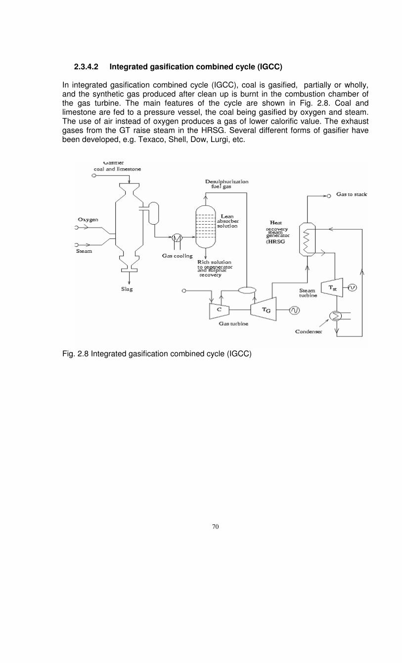
2.3.4.2 Integrated gasification combined cycle (IGCC)
In integrated gasification combined cycle (IGCC), coal is gasified, partially or wholly, and the synthetic gas produced after clean up is burnt in the combustion chamber of the gas turbine. The main features of the cycle are shown in Fig. 2.8. Coal and limestone are fed to a pressure vessel, the coal being gasified by oxygen and steam. The use of air instead of oxygen produces a gas of lower calorific value. The exhaust gases from the GT raise steam in the HRSG. Several different forms of gasifier have been developed, e.g. Texaco, Shell, Dow, Lurgi, etc.
Fig. 2.8 Integrated gasification combined cycle (IGCC)

71
No ash is to be accessed by the GT blades. Filtration of ash is essential to prevent entry to turbine. Powdered coal (coarse) is gasified in a fluidised bed coal gasifier in presence of oxygen and steam to produce mainly the methane gas which burns directly in the combustor of the GT plant. The GT drives the compressor to supply air to the pressurized gasifier as well as to the combustion chamber and generates electricity through the alternator mounted on a shaft. During the gasification process, limestone (CaCO3 + MgCO2) used as the bed material. These converts into CaO and CO2 at high temperature. CaO reacts with sulphur present in coal to produce CaS which is recycled to the regenerator where CaO is reformed and elemental S is produced. The hot exhaust gases from GT are passed through a heat recovery boiler in a conventional steam plant.
CaCO3 → CaO + CO2
2CaO+S→2CaS+O2 CaS+O2= CaO+S
2.3.5 MHD-STEAM POWER PLANT
The maximum steam temperature and pressure being fixed from metallurgical considerations, the minimum temperature being fixed by the ambient conditioned and optimum number of reheat and regeneration, the ceiling for the conversion efficiency of

72
a conventional thermal power station is somewhere near 44-45%. There is a great deal of world wide importance to achieve a higher conversion efficiency and hence fuel economy by converting “heat” directly to electricity by eradicating the link process of producing mechanical energy (shaft work) via steam. Of all the direct energy conversion methods exploitable, the MHD power generation seems to be most promising for a utility system. The maximum limiting temperature of turbine blades being 750-800 0C, the MHD generator is capable of tapping the vast potential offered by modern furnaces which can reach to about 3000 K with preheating of air.
2.3.5.1 PRINCIPLES OF MHD GENERATOR
FARADAY’s law of electromagnetic induction states that when a conductor and a magnetic field move relative to each other, an electric voltage is induced in the conductor. The conductor may be solid, liquid or a gas. In a MHD generator, the hot ionised gas replaces the copper winding of the alternator. When a gas is heated to high temperature, the valance electrons of the excited atoms move on to higher quantized orbits, and ultimately at certain energy levels, they fly off and become free electrons for a gas to be conducting. A certain number of free electrons must be present along with an equal number of ions on the main body of the neutral atoms. Since a very high temperature is required to ionise a gram mole of atoms (ionisation potential), the same can not be conducted by the matters available. Hence the hot gas is seeded with an alkali metal such as Cesium (Cs) or Potassium (K2CO3 in water or KOH) having a low ∆H, before the gas enters the MHD duct. Adequate electrical conductivity of about 10 mho/m can thus be realised at temperature 2200-2700 0C
Fig. 2.10 Schematic diagram of a MHD generator. .The duct through which the electrically conducting ionised gas flows has two sides supporting a strong transverse magnetic field of 4-5 tesla and the other sides forming the electrodes as shown in Fig. 2.10.

73
Power generated per unit length is ρ
σ 2
bu∞
where σ is the thermal conductivity u is the velocity of the ionised gas b is the field strength ρ is the density of the gas
2.3.5.2 MATERIALS
Duct walls: To withstand temperature above 2200 0C corrosive atmosphere of alkali seeded gases. Magnesium Oxide, Stronsium, Zirconite, Hafnia Electrodes: Tungsten or Carbon Electromagnets: Consumes lot of electricity. To reduce the power consumption of these electromagnets, cryogenic or superconducting coils at liquid helium temperatures are suggested.
If the high temperature gas ( 03000 C� ) entering the MHD duct could be expanded to the ambient temperature of 030 C , the Carnot efficiency would have reached 90 % . Unfortunately, the MHD power output is restricted because by the time the gas temperature falls below 02000 C , the electrical conductivity becomes very low with the electrons combining with ions to form neutral atoms and generators ceases to operate. Therefore, MHD generator is used as a topping unit and the MHD exhaust at about
02000 C is utilized in raising steam to drive turbine and generate electricity in a conventional steam power plant as bottoming plant as shown in Fig. 2.11.

74
Fig. 2.11 An open cycle MHD-steam power plant. In open cycle scheme the products of combustion with highly preheated air are seeded with 1% potassium before they enter the MHD duct at 2500 K – 3000 K, where some part of the internal energy of the gas (in plasma state) is directly converted into electricity. Direct current produced is converted to ac power with the help of an inverter. The high temperature exhaust from the MHD duct is then used in preheating of air and in raising steam. In the steam cycle, the feedwater heaters and reheaters are not shown in the figure. The combustion air can also be preheated indirectly using an auxiliary combustion system. Oxygen enriched air is used when the preheated air temperature is not high enough. Since the products of combustion are exhausted to atmosphere, the oxides and hydroxides of the seeding element cause severe air pollution. The use of an electrostatic precipitator helps in recovery of the seed, which can be used again, and also in the abatment of atmospheric pollution. 2.3.5.3 COAL AS FUEL FOR MHD
Although most of the developmental efforts on MHD were based on fuels like natural gas, kerosene, bebzene, tolune, fuel oil, etc, coal is said to be the better fuel, because it contains less hydrogen, and thus the sink of electrons in the flow created by OH-ions is reduced. Only fuel better than coal is char or devolatalized coal, which contains almost no hydrogen and, in general results in 25 % increase in the performance of the generator. With char as a fuel, following advantages were reported:

75
1. No deterioration of channel through chemical or thermal action of coal-slag deposits. Slag deposits protect the electrodes and insulators and improve the breakdown properties of the channel by reducing the electrical field gradient in the flow direction.
2. No deterioration of electrical performance of the duct 3. No loss of insulator property through penetration of potassium seed by coal
combustion products. An MHD-steam power plant with coal as fuel is shown in Fig. 2.12
Fig. 2.12 MHD-steam power plant operated with coal.
2.3.6 THERMIONIC GENERATOR A Thermionic generator transforms “heat” directly into electricity by utilizing thermionic emission. Metal has free electrons. A metal electrode (called emitter) is heated until it is hot enough to release electrons from it. The electron crosses a small gap and accumulate on a cooled metal electrode (called collector). To minimize energy losses as electrons cross the gap, the space between the two electrodes is either maintained at a very high vacuum or filled with a highly conducting cesium vapour. It is essentially a low voltage and high current device. The emission of an electron from a metal surface is opposed by a potential barrier equal to the difference between the energies of an electron outside and inside to the metal. Thus a certain amount of energy must be spent to release the electron from the surface, which is known as surface work function (Φ ). The lower the work function the easier to release electron from the metal surface. Further, work function varies from metal to metal. (1-5 eV). Maximum electron current per unit area is given by Richardson-Dushman equation

76
2 expSJ ATTκ
Φ� �= −� �� �
(2.8)
where
sJ = Current density of the emission (mA/mm2) A = Richardson’s constant (approx. 1202 mA/mm2K2) Φ =Work function of the cathode material (J) κ = Boltzmann constant (1.38066E-23 J/K) The kinetic energy of the free electrons at absolute zero would occupy quantum states, or discrete energy levels from zero up to some maximum value defined by Fermi energy level, fε . Each energy level contains a limited number of free electrons just like an electron orbit containing a limited number of electrons. Above absolute zero temperature, some electrons may have energies higher than the Fermi level. The electrons may be assumed to be vibrating about fε with an amplitude of vibration depending upon the temperature. The energy that must be supplied to overcome the weak attractive force on the outermost orbital electrons is the work function Φ , so that the electron leaving the emitter has an energy level fεΦ + . When heat is supplied to the emitter, some of the high energy free electrons at the Fermi level get the necessary energy- energy equal to emitter work function cΦ to escape the emitter surface- move through the gap, strike the collector and give up their K.E. ( fε ( )a ) plus energy equal to collector (anode) work function aΦ . This energy is rejected as heat from the low temperature collector. The electron energy is reduced to the Fermi energy level of the anode, fε ( )a , but this energy state is higher than that of the electron at Fermi energy level of the cathode,
fε ( )c , so that the electron can pass through the external load from anode to cathode. Cathode materials should thus have very low Fermi level while anode materials must have high Fermi levels. The positively charged cathode tends to pull the electrons back and the electrons already in the gas exert a retarding force on the electrons trying to cross. This produces a space charge barrier. Figure ….. presents a thermionic generator with an interspace retarding potential equivalent to δ volts above the anode work function aΦ . Due to this potential barrier, C CV > Φ and a aV > Φ , and the current density from cathode to anode and that from anode to cathode (back emission) are given by
2 exp CC C
C
VJ AT
Tκ� �
= −� �� �
amp/cm2 (2.9)
2 exp AA A
A
VJ AT
Tκ� �
= −� �� �
amp/cm2 (2.10)

77
The output voltage across the electrical resistance ( 0R )
( ) ( )0
1C A C A f fV V V a c
eφ ε ε� �= − = Φ − = −
(2.11)
Each electron must overcome the inter space potential ( C CV − Φ ) and the work function
CΦ as it leaves the cathode. In doing this work, it carries away the net energy
( )1C C C C C C CQ J V J V= − Φ + Φ = W/cm2 (2.12)
Fig. 2.13 Schematic diagram of a thermionic generator Each electron also carries away its own K.E. which is 2 cKT . This component of energy transfer is
2
2 C
C C
TQ J
eκ= W/m2
(2.13)
The back emission from the anode must similarly carry energy to the cathode. The net rate of energy supply to the cathode would thus be
1
2 2 -c a
c c a a
T TQ J V J V
e eκ κ� � � �= + +� � � �
� � � �
(2.14)
where 191.603 10e −= × coulomb The power output from the generator is
( )0 c aW V J J= − (2.15)
The thermal efficiency of the thermionic generator would be given by

78
( )0
2 2 -
c a
c ac c a a
V J JT T
J V J Ve e
ηκ κ
−=
� � � �+ +� � � �� � � �
(2.16)
where 0 c aV V V= − . Substituting
C
c
c
VT
βκ
= (2.17)
a
a
a
VT
βκ
= (2.18)
and c
a
TT
θ= (2.19)
The efficiency can be written as
( ) ( )2 2
c c a a c a
c ac c c a a a
T T J JT T
J T J Te e
β κ β κη
κ κβ κ β κ
− −=
� � � �+ − +� � � �� � � �
( ) ( )( ) ( ) ( )
2
2
1 exp
2 2 expc a c a
c c c a
β θβ θ β ββ θ β θ β β
� �− − − =+ − + −
(2.20)
It is found that for all values of ,θ the efficiency curve peaks are very near to the value of aβ equal to cβ . Putting, ,c aβ β= Eq. 2.20 becomes
[ ] ( )( )
2
max2
11
221
2
β θη θβ θβ θβ
� �� �−� �= −� �++
−� �+
(2.21)
Now,
( )( )
2
2
11
21
2
θβ θ
θβ
� �� �−� �≈� �+
−� �+
,
so that
[ ]max 12
βη θβ
= −+
(2.22)

79
Here, ( )1 θ− , i.e. 1 a
c
TT
� �−� �
� � is the Carnot cycle efficiency. If 18β = ,
( )max 0.9 1η θ= − (2.23)
Again, maxη occurs when a cβ β= , i.e.
c a
c a
V VT T
= (2.24)
To reduce the space charge barrier and to promote electron emission from the cathode, ionized cesium vapour is made to fill the gap. To achieve a higher degree of ionization of the cesium, the emitter temperature must be of the range 01500 1600 C− . Emitter Materials: Tungsten or rhenium. For use in corrosive environment, emitters are usually coated with ceramic shields. Collector Materials: Molybdenum coated with cesium. 2.3.6.1 THERMIONIC GENERATOR AS TOPPING UNIT
(1) The fuel element of nuclear reactors may be the most suitable high temperature heat sources for thermionic generators (Fig. 2.14). The fuel element 1 containing the fissile material carries the cathode 2 which is surrounded by the anode 3 separated from the cathode by a space 4 filled with ionized cesium vapour. The anode is cooled outside by the coolant flowing through the annulus 5. Some of the energy released by nuclear fission is thus directly convereted to electricity by thermionic means, and the remainder is converted in a bottoming steam plant, yielding a higher overall plant efficiency.
Fig. 2.14 Nuclear fuel clad attached with thermionic generator

80
(2) In the conventional steam generator (fossil fuelled), the riser tubes are located in the radiant zone of the furnace. The energy of high temperature combustion gases can be partly converted into electricity if the riser tubes are provided with cathode and anode of a thermionic generator with the inter space filled with ionized cesium vapour (Fig. 2.15). The use of the hot combustion gases to produce extra energy before the steam cycle in a topping unit improves the overall plant efficiency.
Fig. 2.15 Thermionic generator attached to the riser of a steam generator
(3) Another interesting application is in a topping cycle combining an MHD generator with a thermionic generator (Fig. 2.16). The waste heat from the MHD generator is often as high as 01900 C . The thermionic device could utilize this heat prior to its use in a conventional steam cycle. With addition of a thermionic device between the MHD and steam plant, estimates indicate that the overall plant efficiency could be increased by 5%.

81
Fig. 2.16 A combined MHD, thermionic and steam generator 2.3.7 THERMOELECTRIC GENERATOR When two dissimilar wires A and B are maintained at two different temperatures a potential difference is developed. It is called the Seebeck effect and it is the basis of temperature measurement by a thermocouple. The Seebeck coefficient or thermoelectric power is defined as
, 0limA B T
VT
α∆ →
∆=∆
(2.24)
When a current (I) flows through a junction of two dissimilar materials, the amount of heat over and above the Joulean heat ( )2
jI R which has to be removed from or
absorbed by the junction to maintain it isothermal is called the Peltier heat ( ),A BQ which
is proportional to the current I so that
, ,A B A BQ Iπ=
where ,A Bπ is the Peltier coefficient. In most of the thermocouple materials (like copper-constantant, Iron-constantant, etc), the Seebeck coefficient is very low
,( 60.6 V/K)A Bα µ= . Hence, emf generated is extremely low. However, in materials like
germanium-silicon, the Seebeck coefficient is high ,( 830 V/K)A Bα µ= . Hence, thermoelectric effect will be significant with semiconductor materials. 2.3.7.1 PRINCIPLE OF OPERATION A thermoelectric generator is similar to the thermocouple with the difference that the thermo-elements are made up of semiconductors p and n , and heat is supplied to the

82
hot junction and from the cold junction heat is removed, both the junctions being made of copper. Let,
1T = temperature of the source (K)
0T = temperature of the sink (K) , p nL L = length of the thermoelectric element (m)
, Ap nA = cross-sectional area of thermoelectric elements ( 2m )
, p nκ κ = thermal conductivity of the elements ( W/mK)\
, p nρ ρ = electric resistivity of elements (ohm-m)
, p nK K = thermal conductance of the elements, A
Lκ
(W/K)
, p nR R = electrical resistance of the element, L
Aρ
(ohm)
, p nα α = Seeback coefficient (V/K)
, p nπ π = Peltier coefficient (V) Applying the first law of thermodynamics to the upper plate as the control volume (Fig. 2.17), the temperature difference ( )1 0T T− will generate a Seeback voltage ( ), 1 0p n T Tα −
and a resultant current I will flow when load LR is placed in the circuit. The heat flowing into the hot junction is 1Q which is balanced by the heat conducted into the two legs kQ , the Peltier heat pQ at the junction due to the current flowing in the
circuit, and the heat flowing into the junction as a result of the Joule heat 12 jQ . It is
being assumed that half the Joulean heat appears at each junction. Therefore,

83
Fig. 2.17 A simple circuit for thermoelectric generator
. . . .
1
12 j P KQ Q Q Q+ = + (2.25)
where, .
, , 1p n p npQ I ITπ α= =
( ).
2 2p P n nj p n
P n
L LQ R R I I
A A
ρ ρ� �= + = +� �
(2.26)
( )( ) ( ).
1 0 1 0p P n n
k p nP n
A AQ K K T T T T
L L
κ κ� �= + − = + −� �
(2.27)
On substitution,
( ).
21 , 1 1 0
12
p p p pn n n np n
p n p n
L AL AQ IT I T T
A A L L
ρ κρ κα� � � �
= − + + + −� � � �� � � �
(2.28)
The useful power generated is 2
2 LL L
L
VW I R
R= =
(2.29)
where, voltage across the load is given by
( ) ( ). 1 0L p n p nV T T I R Rα= − − + (2.30)

84
By Kirchhoff’s law
( ), 1 0p n
L p n
T TI
R R R
α −=
+ +
(2.31)
Let m be the resistance ratio defined,
L
p n
Rm
R R=
+ (2.32)
so that
1 p n L
p n
R R Rm
R R
+ ++ =
+
(2.33)
From Eqs. (2.31) and (2.32), ( )
( ) ( ), 1 0
1p n
p n
T TI
R R m
α −=
+ +
(2.34)
The useful power is
( )( ) ( )
( ) ( )( )2 22 2.
, 1 0 , 1 02 22 11
p n p nL p n
p np n
T T T TmW R R m
R RmR R m
α α− −= + =
+++ +
(2.35)
and the heat input (Eq. (2.28)) is
( )( )( )
( )( ) ( ) ( )( )
22., 1 01 1 02
1 , 1 02
121 1
p np n p n
p n p n
T TT T TQ K K T T
R R m m R R
αα
−−= − + + −
+ + + +
(2.36)
Efficiency of the thermoelectric generator is
( )( )
( )( )( )
( )( ) ( ) ( )( )
22
1 02
221 1 02 1 1 0
1 02
.1
0.51 1
pn
p n
pnpn p n
p n p n
mT T
R RmWQ T TT T T
K K T TR R m m R R
α
ηα
α
−++
= =−−
− + + −+ + + +
( ) ( )( )( )1 0
21 1 0
21 1
11 0.5 p n p n
pn
T T mT K K R R mT T
mT Tα
−=+ + +−+ − +
(2.36)
Let, ( )( )2pn
p n p n
ZK K R R
α=
+ +
Where Z is defined as the figure of merit. It depends on the material properties of the semiconductor pairs selected. From Eq. (2.36), efficiency in terms of figure of merit is
( ) ( )1 0
21 1 0
1 1
11 0.5
T T mT mT T
mT zT
η −=+−+ − +
(2.37)

85
From the above equation, it is clear that efficiency increases with the figure of merit. Let, p nR R R= + and p nK K K= + .
2
.pnZ
R K
α∴ =
(2.38)
Now, efficiency η is maximum if the figure of merit Z is maximum for which the product R.K should be minimum.
. .p p p pn n n n
p n p n
L k AL k AR K
A A L L
ρ ρ� � � �= + +� � � �� � � �
(2.39)
Let, pP
p
AL
γ = and nn
n
AL
γ = where p n,γ γ are the aspect ratios.
. .p np p n n
p n
R K k kρ ρ γ γγ γ� �
� �∴ = + +� � � �
(2.40)
Minimizing .R K will result in
2
min. p p n nR K k kρ ρ� �= + (2.41)
Maximum value of figure of merit is 2
max pn
p p n n
Zk k
αρ ρ
� �� �∴ =
+� �
(2.42)
Hence, maximum efficiency is
( ) ( )1 0
max 21 1 0
1 max 1
11 0.5
T T mT mT T
mT z T
η −=+−+ − +
(2.43)
Dependency of efficiency on resistance ratio (m) For given temperatures, maximum figure of merit with a given pair of material, efficiency depends on the resistance ratio, m. To find the optimum resistance ratio
0ddm
η = (2.44)
1 0
12
2 1 T Topt om m Z +� �∴ = = +
(2.45)
By rearranging
1 0 1+ .1 2o
o
Z T Tm
m+∴ =
− (2.46)
Now,

86
( )( ) ( )
1 0 12
1 1 112
1
1.
1 1 0.5 .11
o
oo
oo
T T m ZTZT T T ZTT m
T mm
η
� �� �− � �= −� �+ − +� �++
(2.47)
or,
( )( ) ( ) ( )
1 02
1 01 1 0.5o
o o
T T m Z
m m ZT Z T Tη
−=
+ + + − −
(2.48)
On simplification, 1 0 0
10
1
1.
o
T T mTT mT
η − −=+
(2.49)
Power developed
( )( )
( )22.
12 .
1pn o
Lp n
T TmW
R Rm
α −=
++
(2.50)
To find the optimum resistance ratio m for a given pair of elements .
0 1Ld Wm
dm= =
Therefore,
( )22.1 01
4pn
L
p n
T TW
R R
α −=
+
(2.51)
The corresponding efficiency is given by
1 0max
1 01
1 1
1.
42 0.5
T TT TT
T ZT
η −= −− +
(2.52)
Advantages of thermoelectric generator
1. Simple 2. Compact 3. Absence of moving part 4. Self-contained 5. Reliable
Effect of figure of merit on efficiency and power output For a particular temperature input, with increase in figure of merit, efficiency increases.
( )( )2pn
p n p n
ZK K R R
α=
+ +
(2.53)
Pure metals and metal alloys have low values of Z which indicates low efficiency.

87
For typical metal
40 /V Kα µ= 60.5 10 ohm-mρ −= ×
10 / = 1 kW/mKk W cmK= Assuming , p n p nk kρ ρ= =
5 -18 10 KZ −= × Thus efficiency will be very low. On the other hand, semiconductors are having greater values of Z , hence used for thermoelectric generators. Materials for thermoelectric generator Materials for thermoelectric generator is chosen such that figure of merit Z is high. The same can be obtained by using materials of
(1) Large Seebeck coefficient (2) Small thermal conductivity (3) Small electric resistance
Following are some of the materials used for thermoelectric generator Table 2.1: Tellurium based alloys Sl No Material Formula Figure of
Merit ( )1 Z K −
1 Lead Telluride PbTe 31.5 10−× 2 Bismuth Telluride ( doped with
Sb or Se ) 2 3Bi Te 34.0 10−×
3 Germanium Telluride GeTe 31.5 10−×
1. Oxides of metal such as 2 3 2 2, , Cr O MnSi MoSi ( 15 20%η ≅ − ) 2. Silicates of some metals 3. Cesium Sulphide CeS ( -3 -1 =1.0 10 KZ × ) 4. Borides 5. Carbides
Output of a single thermoelectric generator is low. Hence usual practice i to generate power with such device is to connect multiple number of p-n junctions in series as shown in Fig. 2.18.

88
Fig. 2.18 Thermoelectric generator in series. Applications to waste heat recovery (a) Thermoelectric generator can be used for waste heat recovery . Figure 2.19 presents the arrangement of an array of TEG on the outside surface of a chimney of a steam power plant. Between each pair of p-n junctions, electric and thermal insulations are provided. Waste heat passing through the stack will be the input for the p-n junctions. As a result heat energy will be directly converted into electricity.
Fig. 2.19 Thermoelectric generator for waste heat recovery from the stack of a steam power plant.

89
(b) Figure 2.20 presents an arrangement for recovery of waste heat for electricity generation from the nuclear pin. P-n junctions are attached to the nuclear pin which is within a cladding.
Fig. 2.20 Thermoelectric generator for heat recovery from a nuclear fuel pin. (c) Another possible application of thermoelectric generator is the combined TEG-steam cycle. TEG will operate as topping cycle. Heat rejected from TEG will be utilised by a waste heat boiler to produce steam which in turn will produce power in a turbine-generator.
Fig. 2.21 Thermoelectric – steam power plant with thermoelectric generator as topping plant