chapter - 2 structural design of rcc building components · 2014-05-26 · ©bsnl india for...
TRANSCRIPT

©BSNL India For Internal Circulation Only Page: 1
Chapter - 2
STRUCTURAL DESIGN
OF
RCC BUILDING
COMPONENTS
Rajendra Mathur Dy. Dir(BS-C) 09412739 232(M)
e-mail – [email protected]

©BSNL India For Internal Circulation Only Page: 2
Structural Design of RCC Building Components
1.0 Introduction
The procedure for analysis and design of a given building will depend
on the type of building, its complexity, the number of stories etc. First
the architectural drawings of the building are studied, structural sys tem
is finalized sizes of structural members are decided and brought to the
knowledge of the concerned architect. The procedure for structural
design will involve some steps which will depend on the type of
building and also its complexity and the time ava ilable for structural
design. Often, the work is required to start soon, so the steps in design
are to be arranged in such a way the foundation drawings can be taken
up in hand within a reasonable period of t ime.
Further, before starting the structural design, the following
information of data are required: (i) A set of architectural drawings;(i i)
Soil Investigation report (SIR) of soil data in l ieu thereof; (iii)
Location of the place or city in order to decide on wind and seismic
loadings;(iv) Data for l ifts, water tank capacit ies on top, special roof
features or loadings, etc.
Choice of an appropriate structural system for a given building is
vital for its economy and safety. There are two type of building
systems:-
(a) Load Bearing Masonry Buildings.
(b) Framed Buildings.
(a) Load Bearing Masonry Buildings: -
Small buildings like houses with small spans of beams, slabs
generally constructed as load bearing brick walls with reinforced
concrete slab beams. This system is suitable for building up to four or
less stories.(as shown in fig. below). In such buildings crushing
strength of bricks shall be 100 kg/cm2
minimum for four stories. This
system is adequate for vertical lo ads it also serves to resists horizontal
loads like wind & earthquake by box action . Further, to ensure its
action against earthquake , it is necessary to provide RCC Bands in
horizontal & vertical reinforcement in brick wall as per IS: 4326-
1967( Indian Standards Code of Practice for Earthquake Resistant
Construction of Buildings.) . In some Buildings, 115mm thick brick
walls are provided since these walls are incapable of supporting
vertical loads, beams have to be provide along their lengths to support
adjoining slab & the weight of 115mm thick brick wall of upper
storey. These beams are to rest on 230 mm thick brick walls or
reinforced concrete columns if required. The design of Load Bearing

©BSNL India For Internal Circulation Only Page: 3
Masonry Buildings are done as per IS:1905-1980 (Indian Standards
Code of Practice for Structural Safety of Buildings: Masonry
Walls(Second Revision).
Load bearing brick wall
Structural system
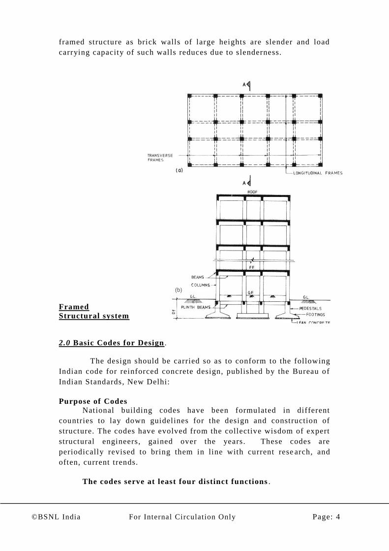
(b) Framed Buildings:-
In these types of buildings reinforced concrete frames are
provided in both principal directions to resist vertical loads and the
vertical loads are transmitted to vertical framing system i.e columns
and Foundations. This type of system is effective in resisting both
vertical & horizontal loads. The brick walls are to be regarded as non
load bearing filler walls only. This system is suitable for multi -storied
building which is also effective in resisting horizontal loads due to
earthquake. In this system the floor slabs, generally 10 0-150 mm thick
with spans ranging from 3.0 m to 7.0 m. In certain earthquake prone
areas, even single or double storey buildings are made framed
structures for safety reasons. Also the single storey buildings of large
storey heights (5.0m or more ) ,l ike electric substation etc. are made
©BSNL India For Internal Circulation Only Page: 4
framed structure as brick walls of large heights are slender and load
carrying capacity of such walls reduces due to slenderness.
Framed
Structural system
2.0 Basic Codes for Design .
The design should be carried so as to conform to the following
Indian code for reinforced concrete design, published by the Bureau of
Indian Standards, New Delhi:
Purpose of Codes
National building codes have been formulated in different
countries to lay down guidelines for the design and construction of
structure. The codes have evolved from the collective wisdom of expert
structural engineers, gained over the years. These codes are
periodically revised to bring them in line with current rese arch, and
often, current trends.
The codes serve at least four distinct functions .

©BSNL India For Internal Circulation Only Page: 5
Firstly, they ensure adequate structural safety, by specifying certain
essential minimum requirement for design.
Secondly, they render the task of the designer relatively simple; often,
the result of sophisticate analyses is made available in the form of a
simple formula or chart .
Thirdly, the codes ensure a measure of consistency among different
designers.
Finally, they have some legal validity in that they protect the structural
designer from any l iabili ty due to structural failures that are caused by
inadequate supervision and/or faulty material and construction.
(i)IS 456 : 2000 – Plain and reinforced concrete – code of practice
(fourth revision)
(ii) Loading Standards
These loads to be considered for structural design are specified in the
following loading standards:
IS 875 (Part 1-5) : 1987 – Code of practice for design loads
(other than earthquake) for buildings and structures (second
revision)
Part 1 : Dead loads
Part 2 : Imposed (live) loads
Part 3 : Wind loads
Part 4 : Snow loads
Part 5 : Special loads and load combinations
IS 1893 : 2002 – Criteria for earthquake resistant design of
structure (fourth revision) .
IS 13920 : 1993 – Ductile detailing of reinforced concrete structure
subject to seismic forces.
Design Handbooks
The Bureau of Indian standards has also published the following
handbooks, which serve as useful supplement to the 1978 version of the
codes. Although the handbooks need to be updated to bring them in
line with the recently revised (2000 version) of the Code, many of the
provisions continue to be valid (especially with regard to structural
design provisions).
SP 16 : 1980 – Design Aids (for Reinforced Concrete) to IS 456 :
1978
SP 24 : 1983 – Explanatory handbook on IS 456 : 1978
SP 34 : 1987 – Handbooks on Concrete Reinforced and Detailing.
General Design Consideration of IS: 456-2000.

©BSNL India For Internal Circulation Only Page: 6
The general design and construction of reinforced concrete buildings shall be
governed by the provisions of IS 456 –2000
AIM OF DESIGN
The aim of design is achievement of an acceptable probability that structures being
designed shall, with an appropriate degree of safety –
Perform satisfactorily during their intended life.
Sustain all loads and deformations of normal construction & use
Have adequate durability
Have adequate resistance to the effects of misuse and fire.
METHOD OF DESIGN –
Structure and structural elements shall normally be designed by Limit State
Method.
Where the Limit State Method cannot be conveniently adopted, Working
Stress Method may be used
MINIMUM GRADE OF CONCRETE
The minimum grade of concrete for plain & reinforced concrete shall be as per table
below –
26.4 Nominal Cover to Reinforcement
©BSNL India For Internal Circulation Only Page: 7
26.4.1 Nominal Cover
Nominal cover is the design depth of concrete cover to all steel
reinforcements, including links. It is the dimension used in design and
indicated in the drawings. It shall be not less than the diameter of the bar.
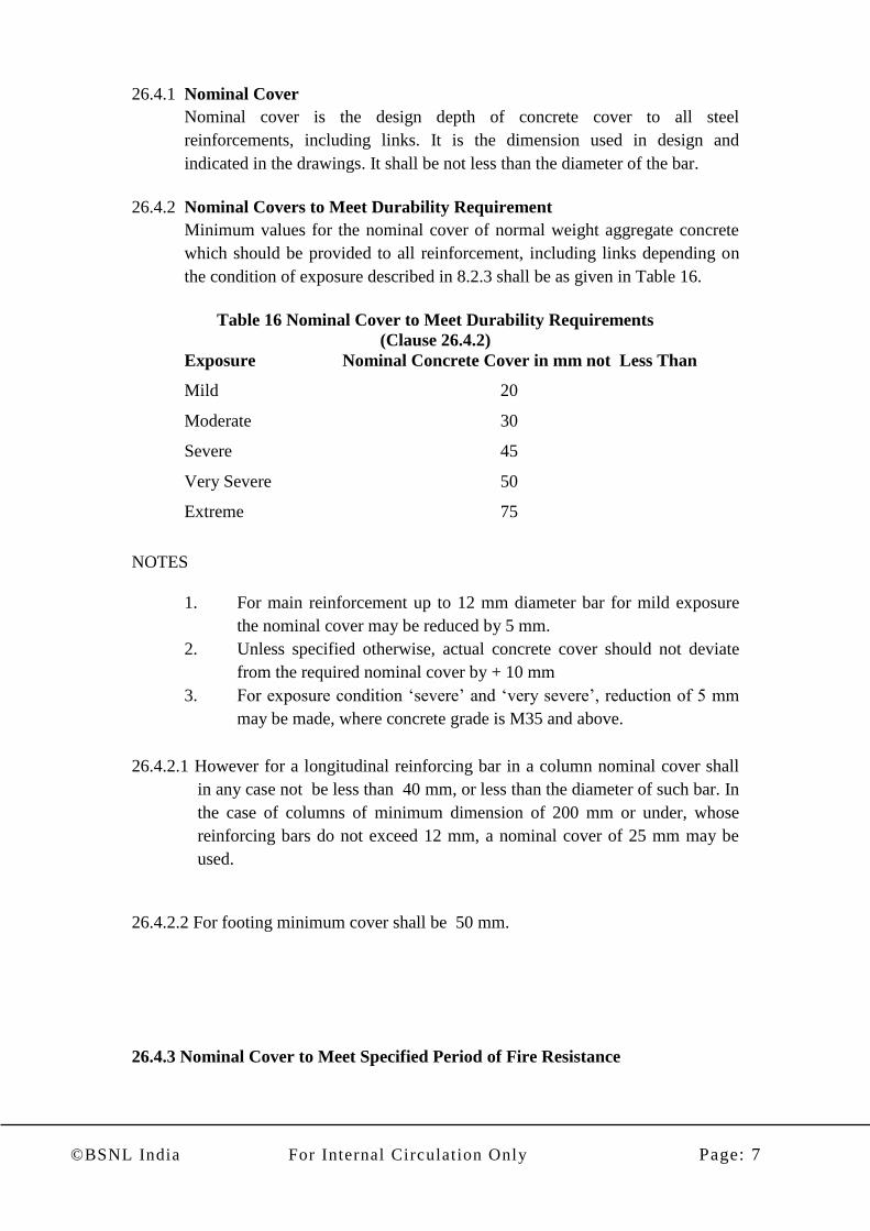
26.4.2 Nominal Covers to Meet Durability Requirement
Minimum values for the nominal cover of normal weight aggregate concrete
which should be provided to all reinforcement, including links depending on
the condition of exposure described in 8.2.3 shall be as given in Table 16.
Table 16 Nominal Cover to Meet Durability Requirements
(Clause 26.4.2)
Exposure Nominal Concrete Cover in mm not Less Than
Mild 20
Moderate 30
Severe 45
Very Severe 50
Extreme 75
NOTES
1. For main reinforcement up to 12 mm diameter bar for mild exposure
the nominal cover may be reduced by 5 mm.
2. Unless specified otherwise, actual concrete cover should not deviate
from the required nominal cover by + 10 mm
3. For exposure condition ‘severe’ and ‘very severe’, reduction of 5 mm
may be made, where concrete grade is M35 and above.
26.4.2.1 However for a longitudinal reinforcing bar in a column nominal cover shall
in any case not be less than 40 mm, or less than the diameter of such bar. In
the case of columns of minimum dimension of 200 mm or under, whose
reinforcing bars do not exceed 12 mm, a nominal cover of 25 mm may be
used.
26.4.2.2 For footing minimum cover shall be 50 mm.
26.4.3 Nominal Cover to Meet Specified Period of Fire Resistance
©BSNL India For Internal Circulation Only Page: 8
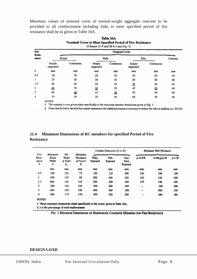
Minimum values of nominal cover of normal-weight aggregate concrete to be
provided to all reinforcement including links to meet specified period of fire
resistance shall be as given in Table 16A.
21.4 Minimum Dimensions of RC members for specified Period of Fire
Resistance
DESIGN LOAD
©BSNL India For Internal Circulation Only Page: 9
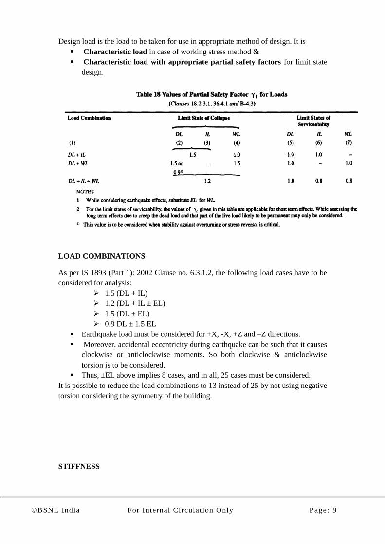
Design load is the load to be taken for use in appropriate method of design. It is –
Characteristic load in case of working stress method &
Characteristic load with appropriate partial safety factors for limit state
design.
LOAD COMBINATIONS
As per IS 1893 (Part 1): 2002 Clause no. 6.3.1.2, the following load cases have to be
considered for analysis:
1.5 (DL + IL)
1.2 (DL + IL ± EL)
1.5 (DL ± EL)
0.9 DL ± 1.5 EL
Earthquake load must be considered for +X, -X, +Z and –Z directions.
Moreover, accidental eccentricity during earthquake can be such that it causes
clockwise or anticlockwise moments. So both clockwise & anticlockwise
torsion is to be considered.
Thus, ±EL above implies 8 cases, and in all, 25 cases must be considered.
It is possible to reduce the load combinations to 13 instead of 25 by not using negative
torsion considering the symmetry of the building.
STIFFNESS

©BSNL India For Internal Circulation Only Page: 10
22.3.1 Relative Stiffness: The relative stiffness of the members may be based on
the moment of inertia of the section determined on the basis of any one of
the following definitions:
a) Gross
Section
The cross-section of the member ignoring
reinforcement
b) Transformed
Section
The concrete cross-section plus the area of
reinforcement transformed on the basis of modular
ratio
c) Cracked
Section
The area of concrete in compression plus the area of
reinforcement transformed on the basis of modular
ratio
The assumptions made shall be consistent for all the numbers of the
structure throughout any analysis.
22.3.2 For deflection calculations, appropriate values of moment of inertia as
specified in Annexure of IS 456-2000 should be used.
STRUCTURAL FRAMES
22.4 The simplifying assumptions as given in 22.4.1 to 22.4.3 may be used in
the analysis of frames.
ARRANGEMENT OF LIVE LOAD
22.4.1 a) Consideration may be limited to combinations of:
1) Design dead load on all spans with full design live load on two
adjacent spans; and
2) Design dead load on all spans with dull design live load on alternate
spans.
22.4.1 b) When design live load does not exceed three-fourths of the design dead
load, the load arrangement may be design dead load and design live load
on all the spans.
Note: For beams continuous over support 22.4.1 (a) may be assumed.
22.4.2 Substitute Frame: For determining the moments and shears at any floor
or roof level due to gravity loads, the beams at that level together with
columns above and below with their far ends fixed may be considered to
constitute the frame.
22.4.3 For lateral loads, simplified methods may be used to obtain the moments
and shears for structures that are symmetrical. For unsymmetrical or very
tall structures, more rigorous methods should be used.
MOMENT AND SHEAR COFFICIENTS FOR CONTINUOUS BEAMS

©BSNL India For Internal Circulation Only Page: 11
22.5.1 Unless more exact estimates are made, for beams of uniform cross-section
which support substantially uniformly distributed load over three or more
spans which do not differ by more than 15 percent of the longest, the
bending moments and shear forces used in design may be obtained using
the coefficients given in Tables below.
For moments at supports where two unequal spans meet or in case where
the spans are not equally loaded, the average of the two values for the
negative moment at the support may be taken for design.
Where coefficients given in Table below are used for calculation of
bending moments, redistribution referred to in 22.7 shall not be permitted.
22.5.2 Beams Over Free End Supports
Where a member is built into a masonry wall which develops only partial
restraint, the member shall be designed to resist a negative moment at the
face of the support of W1/24 where W is the total design load and 1 is the
effective span, or such other restraining moment as may be shown to be
applicable. For such a condition shear coefficient given in Table below at
the end support may be increased by 0.05.
-------------------------------------------------------------------------------------------------------
BENDING MOMENT COFFICIENTS
-------------------------------------------------------------------------------------------------------
Span Moments Support Moments
-------------------------------------------------------------------------------------
Types of Load Near Middle At Middle At Support At Other
of End Span of interior next to the Interior
span end support Supports
-------------------------------------------------------------------------------------------------------
Dead load and 1 1 1 1
imposed load +-- +-- (- )-- (- )--
(fixed) 12 16 10 12
Imposed load 1 1 1 1
(not fixed) +-- +-- (- )-- (- )--
10 12 9 9
Note: For obtaining the bending moment, the coefficient shall be multiplied by
the total design load and effective span.
-------------------------------------------------------------------------------------------------------
-------------------------------------------------------------------------------------------------------
SHEAR FORCE COFFICIENTS
-------------------------------------------------------------------------------------------------------

©BSNL India For Internal Circulation Only Page: 12
Type of Load At End At Support Next At All Other
Support to the end Support Interior Support
Outer side Inner Side
-------------------------------------------------------------------------------------------------------
Dead load and
imposed load 0.40 0.60 0.55 0.50
(fixed)
Imposed load 0.45 0.60 0.60 0.60
(not fixed)
Note: For obtaining the shear force, the coefficient shall be multiplied by the
total design load.
-------------------------------------------------------------------------------------------------------
CRITICAL SECTIONS FOR MOMENT AND SHEAR
22.6.1 For monolithic construction, the moments computed at the face of the
supports shall be used in the design of the members at those sections. For
non-monolithic construction the design of the member shall be done
keeping in view 22.2.
22.6.2 Critical Section for Shear
The shears computed at the face of the Support shall be used in the design
of the member at that section except as in 22.6.2.1
22.6.2.1 When the reaction in the direction of the applied shear introduces
compression into the end region of the member, sections located at a
distance less than d from the face of the support may be designed for the
same shear as that computed at distance d.
REDISTRIBUTION OF MOMENTS
22.7 Redistribution of moments may be done in accordance with 37.1.1 for
limit state method and in accordance with B-1.2 for working stress
method. However, where simplified analysis using coefficients is adopted,
redistribution of moments shall not be done.
EFFECTIVE DEPTH
23.0 Effective depth of a beam is the distance between the centroid of the area
of tension reinforcement and the maximum compression fibre, excluding
the thickness of finishing material not placed monolithically with the
member and the thickness of any concrete provided to allow for wear.
This will not apply to deep beams.
CONTROL OF DEFLECTION

©BSNL India For Internal Circulation Only Page: 13
23.2 The deflection of a structure or part thereof shall not adversely affect the
appearance or efficiency of the structure or finishes or partitions. The
deflection shall generally be limited to the following:
a) The final deflection due to all loads including the effects of temperature,
creep and shrinkage and measured from the as-cast level of the supports of
floors, roofs and all other horizontal members, should not normally exceed
span/250.
b) The deflection including the effects of temperature, creep and shrinkage
occurring after erection of partitions and the application of finishes should
not normally exceed span/350 or 20mm whichever is less.
23.2.1 For beams, the vertical deflection limits may generally be assumed to be
satisfied provided that the span to depth ratio are not greater than the value
obtained as below:
a) Basic values of span to effective depth ratios for spans up to 10m:
Cantilever 7
Simply supported 20
Continuous 26
b) For spans above 10m, the values in (a) may be multiplied by 10/span in
metres, except for cantilever in which case deflection calculations should
be made.
c) Depending on the area and the type of steel for tension reinforcement, the
value in (a) or (b) shall be modified as per Fig. 4
d) Depending on the area of compression reinforcement, the value of span to
depth ratio be further modified as per Fig. 5
e) For flanged beams, the value of (a) or (b) be modified as per Fig. 6 and the
reinforcement percentage for use in fig. 4 and 5 should be based on area of
section equal to bf d.
Note: When deflections are required to be calculated, the method given
Annexure ‘C’ of IS 456-2000 may be used.

©BSNL India For Internal Circulation Only Page: 14
CONTROL OF DEFLECTION – SOLID SLABS
24.1 General
The provisions of 32.2 for beams apply to slabs also.
NOTES

©BSNL India For Internal Circulation Only Page: 15
1. For slabs spanning in two directions, the shorter of the two spans should be
used for calculating the span to effective depth rations.
2. For two-way slabs of shorter spans (up to 3.5 m) with mild steel
reinforcement, the span to overall depth rations given below may generally
be assumed to satisfy vertical deflection limits for loading class up to 3
kN/m2.
Simply supported slab 35
Continuous slabs 40
For high strength deformed bars of grade Fe 415,the values given above
should be multiplied by 0.8.
Simply supported slab 28
Continuous slabs 32
23.3 Slabs Continuous Over Supports
Slabs spanning in one direction and continuous over supports shall be
designed according to the provisions applicable to continuous beams.
23.4 Slabs Monolithic with Supports Bending moments in slabs (except flat slabs)
constructed monolithically with the supports shall be calculated by taking such
slabs either as continuous over supports and capable of free, or as members of a
continuous frame work with the supports, taking into account the stiffness of such
support. If such supports are formed due to beams which justify fixity at the
support of slabs, then the effects on the supporting beam, such as, the bending of
the web in the transverse direction of the beam, wherever applicable, shall also be
considered in the design of the beams.
23.4.1 For the purpose of calculation of moment in slabs in a monolithic structure, it
will generally be sufficiently accurate to assumed direct members connected to
the ends of such slab are fixed in position and direction at the end remote from
their connection with the slab.
26.5 REQUIREMENT OF REINFORCEMENT FOR STRUCTURAL
MEMBER
26.5.1 Beams
26.5.1.1 Tension reinforcement
(a) Minimum reinforcement:- The minimum area of tension reinforcement shall
not be less than that given by the following:-
As = 0.85
bd fy
where
As = minimum area of tension reinforcement.
b = breadth of beam or the breadth of the web of T-beam.
d = effective depth, and
©BSNL India For Internal Circulation Only Page: 16
fy = characteristic strength of reinforcement in M/mm2
(b) Maximum reinforcement:- the maximum area of tension reinforcement shall
not exceed 0.04bD.
26.5.1.2 Compression reinforcement
The maximum area of comparison reinforcement shall not exceed 0.04 bd.
Comparison reinforcement in beams shall be enclosed by stirrups for effective lateral
restraint.
26.5.1.3 Side face reinforcement
Where the depth of the web in the beam exceeds 750mm, side face reinforcement
shall be provided along the two faces. The total area of such reinforcement shall be
not less than 0.1 % of the web area and shall be distributed on the equally on the two
face at spacing not exceeding 300mm or web thickness whichever is less.
26.5.1.4 Transverse reinforcement in beam for shear torsion
The transverse reinforcement in beam shall be taken around the outer most tension &
compression bars. In T-beams and I-beams, such reinforcement shall pass around
longitudinal bars located close to the outer face of the flange.
26.5.1.5 Maximum spacing of shear reinforcement
Maximum spacing of shear reinforcement means long by axis of the member shall not
exceed 0.75 d for vertical stirrups and d for inclined stirrups at 45” where d is the
effective depth on the section under consideration. In no case shall be spacing exceed
300mm.
26.5.1.6 Minimum shear reinforcement
Minimum shear reinforcement in the form of stirrups shall be provided such that:
Asv 0.4
bsv 0.87 fy
Where
Asv = total cross-sectional area of stirrups legs effective in shear.
Sv = stirrups spacing along the length of the member
B = breadth of the beam or breadth of the web of flange beam, and
fy = characteristic strength of the stirrups reinforcement in N/mm2 which shall not
taken greater than 415 N/mm2
Where the maximum shear stress calculated is less than half the permissible value in
member of minor structure importance such as lintels, this provision need not to be
complied with.
26.5.1.7 Distribution of torsion reinforcement
When a member is designed for torsion torsion reinforcement shall be provided as
below:
©BSNL India For Internal Circulation Only Page: 17
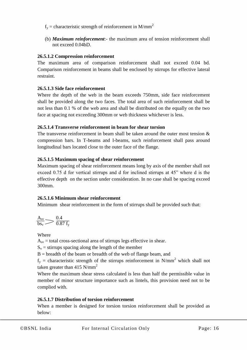
a) the transverse reinforcement for torsion shall be rectangular closed stirrups
placed perpendicular to the axis of the member. The spacing of the stirrups
shall not exceed the list of x1, x1+y1/4 and 300 mm, where x1, y1 are
respectively the short & long dimensions of the stirrup.
b) Longitudinal reinforcement shall be place as closed as is practicable to the
corner of the cross section & in all cases, there shall be atleast one longitudinal
bar in each corner of the ties. When the cross sectional dimension of the
member exceed 450 mm additional longitudinal bar shall be provided to
satisfied the requirement of minimum reinforcement & spacing given in
26.5.1.3.
26.3.2 Minimum Distance between Individual Bars
(a) The horizontal distance between two parallel main reinforcing bars shall
usually be not-less than the greatest of the following:
(i) Dia of larger bar and
(ii) 5 mm more than nominal maximum size of coarse aggregate.
(b) When needle vibrators are used it may be reduced to 2/3rd
of nominal
maximum size of coarse aggregate,
Sufficient space must be left between bars to enable vibrator to be immersed.
(c) Where there are two or more rows of bars, bars shall be vertically in line and
the minimum vertical distance between bars shall be 15 mm, 2/3rd of nominal
maximum size of aggregate or the maximum size of bars, whichever is greater.
26.5.2 Slabs
The rule given in 26.5.2.1 and 26.5.2.2 shall apply to slabs in addition to those given
in the appropriate clause.
26.5.2.1 Minimum reinforcement

©BSNL India For Internal Circulation Only Page: 18
The mild steel reinforcement in either direction in slabs shall not be less than 0.15
percent of the total cross-sectional area. However, this value can be reduced to 0.12
percent when high strength deformed bars or welded wire fabric are used.
26.5.2.2 Maximum diameter
The diameter of reinforcing bars shall not exceed one eight of the total thickness of
slab.
26.3.3 Maximum distance between bars - Slabs
1) The horizontal distance between parallel main reinforcement bars shall not be
more than three times the effective depth of solid slab or 300 mm whichever is
smaller.
2) The horizontal distance between parallel reinforcement bars provided against
shrinkage and temperature shall not be more than five times the effective depth of a
solid slab or 300 mm whichever is smaller.
Torsion reinforcement - Slab
Torsion reinforcement is to be provided at any corner where the slab is simply
supported on both edges meeting at that corner. It shall consist of top and bottom
reinforcement, each with layers of bars placed parallel to the sides of the slab and
extending from the edges a minimum distance of one-fifth of the shorter span. The
area of reinforcement in each of these four layers shall be three-quarters of the area
required for the maximum mid-span moment in the slab.
D-l.9 Torsion reinforcement equal to half that described in D-l.8 shall be provided at a
corner contained by edges over only one of which the slab is continuous.
D-1.10 Torsion reinforcements need not be provided at any comer contained by edges
over both of which the slab is continuous.
26.5.3 Columns
A. Longitudinal Reinforcement
a. The cross sectioned area of longitudinal reinforcement shall be not less than
0.8% nor more than 6% of the gross sectional area of the column. Although it is
recommended that the maximum area of steel should not exceed 4% to avoid
practical difficulties in placing & compacting concrete.
b. In any column that has a larger cross sectional area than that required to support
the load, the minimum percentage steel must be based on the area of concrete
resist the direct stress & not on the actual area.
©BSNL India For Internal Circulation Only Page: 19
c. The bar should not be less than 12 mm in diameter so that it is sufficiently rigid
to stand up straight in the column forms during fixing and concerting.
d. The minimum member of longitudinal bars provided in a column shall be four
in rectangular columns & six in circular columns.
e. A reinforced concrete column having helical reinforcement must have at least
six bars of longitudinal reinforcement with the helical reinforcement. These
bars must be in contact with the helical reinforcement & equidistance around its
inner circumference.
f. Spacing of longitudinal should not exceed 300 mm along periphery of a
column.
g. In case of pedestals, in which the longitudinal reinforcement is not taken into
account in strength calculations, nominal reinforcement should be not be less
than 0.15% of cross sectional area.
B. Transverse Reinforcement
a. The diameter of lateral ties should not be less than ¼ of the diameter of the
largest longitudinal bar in no case should not be less than 6 mm.
b. Spacing of lateral ties should not exceed least of the following:-
Least lateral dimension of the column.
16 times the smallest diameter of longitudinal bars to be tied.
300mm.
SHEAR
40.1 Nominal Shear Stress
The nominal shear stress in beams of uniform depth shall be obtained by the
following equation:
τv = Vu/ b.d
where
Vu = shear force due to design loads;
b = breadth of the member, which for flanged section shall be taken as the breadth of
the web, bw; and
d = effective depth.
40.2.3 With Shear Reinforcement
Under no circumstances, even with shear reinforcement, shall the nominal shear stress
in beams should not exceed given in Table 20.
40.2.3.1 For solid slabs, the nominal shear stress shall not exceed half the appropriate
values given in Table 20.

©BSNL India For Internal Circulation Only Page: 20
40.3 Minimum Shear Reinforcement
When τv, is less than τc given in Table 19, minimum shear reinforcement shall be
provided in accordance with 26.5.1.6.
40.4 Design of Shear Reinforcement
When τv, is exceeds τc , given in Table 19, shear reinforcement shall be provided in
any of the following forms:
a) Vertical stirrups,
b) Bent-up bars along with stirrups, and Where bent-up bars are provided, their
contribution towards shear resistance shall not be more than half that of the total shear
reinforcement.
Shear reinforcement shall be provided to carry a shear equal to Vu – τ c b d. the
strength of shear reinforcement Vus shall be calculated as below:
a) For Vertical Stirrups:
0.87 fy Asv d
Vus = ___________
©BSNL India For Internal Circulation Only Page: 21
Sv
b) For inclined stirrups or a series of bars bent up at different cross –
section:
0.87 fy Asv d
Vus = ___________ (Sin ά + Cos ά)
Sv
c) For single bar or single group of parallel bars, all bent up at the same
cross sections:
Vus = 0.87 fy Asv Sin ά
Where
Asv = total cross –sectional area of stirrups legs or
bent-up bar within a distance Sv,
Sv = spacing of the stirrups or bent-up bars along the
length of the member.
τ v = nominal shear stress,
τ c = design shear strength of the concrete,
b = breadth of the member which for flanged beams,
shall be taken as the breadth of the web bw.
fy = characteristic strength of the stirrup or bent-up
reinforcement which shall not be taken greater
than 415 N/mm2,
ά = angle between the inclined stirrup or bent up bar
and the axis of the member not less than 45o,
and
d = effective depth
DEVELOPMENT LENGTH OF BARS
26.2 Development of Stress in Reinforcement
The calculated tension or compression in any bar at any section shall be developed on
each side of the section by an appropriate development length or end anchorage or by
a combination thereof.
Development length Ld is given by

©BSNL India For Internal Circulation Only Page: 22
Ld = υσst /4τbd
υ = nominal diameter of bar, τbd = design bond stress
σst = stress in bar at the section considered at design load
Design bond stress in limit state method for plain bars in tension is given in
clause 26.2.1.1
For deformed bars conforming to IS 1786 these values are to be increased by
60 %.
For bars in compression, the values of bond stress for bars in tension is to be
increased by 25 percent
B. Shear reinforcement (STIRRUPS)
Development length and anchorage requirement is satisfied, in case of stirrups and
transverse ties, when Bar is bent –
• Through an angle of at least 90 degrees (round a bar of at least its own dia) &
is continued beyond for a length of at least 8 φ, or
• Through an angle of 135 degrees & is continued beyond for a length of at least
6 φ or
• Through an angle of 180 degrees and is continued beyond for a length of at
least 4 φ
DUCTILE DETAILING AS PER IS: 13920
• Provisions of IS 13920-1993 shall be adopted in all reinforced concrete
structures which are located in seismic zone III, IV or V
The provisions for reinforced concrete construction given in IS 13920-1993 shall
apply specifically to monolithic reinforced concrete construction. Precast and/or
©BSNL India For Internal Circulation Only Page: 23
prestressed concrete members may be used only if they can provide the same level of
ductility as that of a monolithic reinforced concrete construction during or after an
earthquake.
The definition of seismic zone and importance factor are given in IS 1893-2002.
CODAL PROVISIONS OF IS 13920
5.2 For all buildings which are more than 3 storeys in height, the minimum grade of
concrete shall be M20 (fck = 20 MPa ).
5.3 Steel reinforcements of grade Fe 415 (see IS 1786 : 1985 ) or less only shall be
used. However, high strength deformed steel bars, produced by the thermo-
mechanical treatment process, of grades Fe 500 and Fe 550, having elongation more
than 14.5 percent and conforming to other requirements of IS 1786 : 1985 may also be
used for the reinforcement.
Flexure Members
6.1.2 The member shall preferably have a width-to-depth ratio of more than 0.3.
6.1.3 The width of the member shall not be less than 200 mm.
6.1.4 The depth D of the member shall preferably be not more than 1/4 of the clear
span.
6.2 Longitudinal Reinforcement
6.2.1 a) The top as well as bottom reinforcement shall consist of at least two bars
throughout the member length.
b) The tension steel ratio on any face, at any section, shall not be less than ρmin =
0.24(fck)1/2
/fy ; where fck and fy are in MPa.
6.2.2 The maximum steel ratio on any face at any section, shall not exceed ρmax =
0.025.
6.2.3 The positive steel at a joint face must be at least equal to half the negative steel
at that face.
6.2.4 The steel provided at each of the top and bottom face of the member at any
section along its length shall be at least equal to one-fourth of the maximum negative
moment steel provided at the face of either joint
6.2.6 The longitudinal bars shall be spliced, only if hoops are provided over the entire
splice length, at a spacing not exceeding 150 mm 6.3
Web Reinforcement
6.3.1 Web reinforcement shall consist of vertical hoops. A vertical hoop is a closed
stirrup having a 135° hook with a 10 diameter extension (but not < 75 mm) at each
end that is embedded in the confined core
6.3.2 The minimum diameter of the bar forming a hoop shall be 6 mm. However, in
beams with clear span exceeding 5 m, the minimum bar diameter shall be 8 mm.
6.3.4 The contribution of bent up bars and inclined hoops to shear resistance of the
section shall not be considered.
6.3.5 The spacing of hoops over a length of 2d at either end of a beam shall not
exceed (a) d/4, and (b) 8 times the diameter of the smallest longitudinal bar; however,
©BSNL India For Internal Circulation Only Page: 24
it need not be less than 100 mm. Elsewhere, the beam shall have vertical hoops at a
spacing not exceeding d/2.
Columns
7.1.2 The minimum dimension of the member shall not be less than 200 mm.
However, in
frames which have beams with centre to centre span exceeding 5 m or columns of
unsupported length exceeding 4 m, the shortest dimension of the column shall not be
less than 300 mm.
7.1.3 The ratio of the shortest cross sectional dimension to the perpendicular
dimension shall preferably not be less than 0.4.
7.2 Longitudinal Reinforcement
7.2.1 Lap splices shall be provided only in the central half of the member length. It
should be proportioned as a tension splice. Hoops shall be provided over the entire
splice length at spacing not exceeding 150 mm centre to centre. Not more than 50
percent of the bars shall be spliced at one section.
7.3 Transverse Reinforcement
7.3.1 Transverse reinforcement for circular columns shall consist of spiral or circular
hoops. In rectangular columns, rectangular hoops may be used. A rectangular hoop is
a closed stirrup, having a 135° hook with a 10 diameter extension (but not < 75 mm)
at each end, that is embedded in the confined core.
7.3.3 The spacing of hoops shall not exceed half the least lateral dimension of the
column, except where special confining reinforcement is provided, as per 7.4.
7.4 Special Confining Reinforcement
This requirement shall be met with, unless a larger amount of transverse
reinforcement is required from shear strength considerations.
7.4.1 Special confining reinforcement shall be provided over a length lo from each
joint face, towards midspan, and on either side of any section, where flexural yielding
may occur under the effect of earthquake forces. The length ‘lo’ shall not be less than
(a) larger lateral dimension of the member at the section where yielding occurs, (b)
1/6 of clear span of the member, and (c) 450 mm.
7.4.2 When a column terminates into a footing or mat, special confining
reinforcement shall extend at least 300 mm into the footing or mat.
7.4.6 The spacing of hoops used as special confining reinforcement shall not exceed
1/4 of minimum member dimension but need not be less than 75 mm nor more than
100 mm.
8 JOINTS OF FRAMES
8.1 The special confining reinforcement as required at the end of column shall be
provided through the joint as well, unless the joint is confined as specified by 8.2.
8.2 A joint which has beams framing into all vertical faces of it and where each beam
width is at least 3/4 of the column width, may be provided with half the special
confining reinforcement required at the end of the column. The spacing of hoops shall
not exceed 150 mm.
©BSNL India For Internal Circulation Only Page: 25
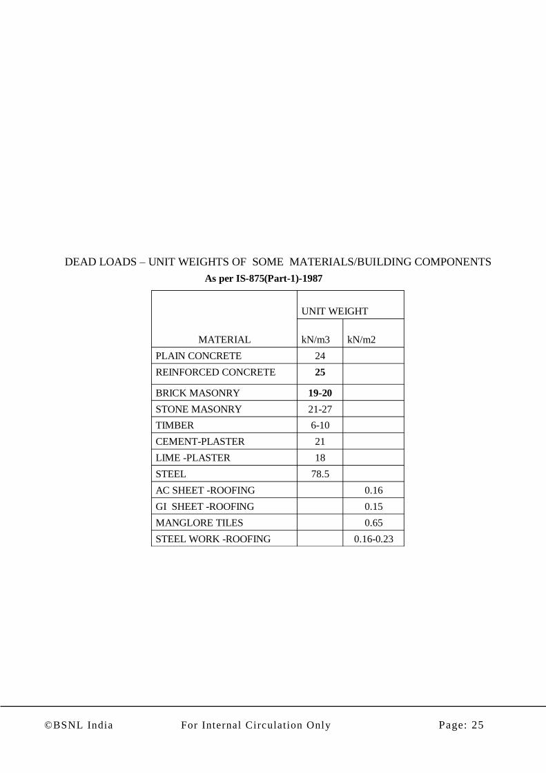
As per IS-875(Part-1)-1987
0.16-0.23STEEL WORK -ROOFING
0.65MANGLORE TILES
0.15GI SHEET -ROOFING
0.16AC SHEET -ROOFING
78.5STEEL
18LIME -PLASTER
21CEMENT-PLASTER
6-10TIMBER
21-27STONE MASONRY
19-20BRICK MASONRY
25REINFORCED CONCRETE
24PLAIN CONCRETE
kN/m2kN/m3
UNIT WEIGHT
MATERIAL
DEAD LOADS – UNIT WEIGHTS OF SOME MATERIALS/BUILDING COMPONENTS
©BSNL India For Internal Circulation Only Page: 26
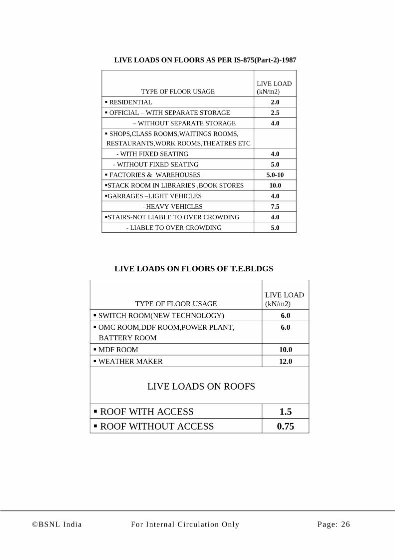
4.0STAIRS-NOT LIABLE TO OVER CROWDING
5.0- LIABLE TO OVER CROWDING
7.5–HEAVY VEHICLES
4.0GARRAGES –LIGHT VEHICLES
10.0STACK ROOM IN LIBRARIES ,BOOK STORES
5.0-10 FACTORIES & WAREHOUSES
5.0- WITHOUT FIXED SEATING
4.0- WITH FIXED SEATING
SHOPS,CLASS ROOMS,WAITINGS ROOMS,
RESTAURANTS,WORK ROOMS,THEATRES ETC
4.0– WITHOUT SEPARATE STORAGE
2.5 OFFICIAL – WITH SEPARATE STORAGE
2.0 RESIDENTIAL
LIVE LOAD
(kN/m2)TYPE OF FLOOR USAGE
LIVE LOADS ON FLOORS AS PER IS-875(Part-2)-1987
0.75 ROOF WITHOUT ACCESS
1.5 ROOF WITH ACCESS
LIVE LOADS ON ROOFS
12.0WEATHER MAKER
10.0MDF ROOM
6.0 OMC ROOM,DDF ROOM,POWER PLANT,
BATTERY ROOM
6.0 SWITCH ROOM(NEW TECHNOLOGY)
LIVE LOAD
(kN/m2)TYPE OF FLOOR USAGE
LIVE LOADS ON FLOORS OF T.E.BLDGS

©BSNL India For Internal Circulation Only Page: 27

©BSNL India For Internal Circulation Only Page: 28
3.0 Steps for Design of a Multi-Storeyed Building:-
Manual Method of Analysis & Design:-
Step1: Study of architectural Drawings:- Before proceeding for structural
design of any building it is ensure that approved working drawings are available
in the office. All working drawings i.e. each floor plan, elevations, sections, are
studied thoroughly & discrepancy if any brought to the notice of concern Architect
for rectification/correction. The problems coming in finalization of structural
configuration may also be intimated to concern Architect for
rectification/correction if any.
Step2: Finalization of structural Configuration. After receiving corrected
working drawing from the architectural wing, the structural system is finalized. The
structural arrangements of a building is so chosen as to make it efficient in resisting
vertical as well as horizontal loads due to earthquake. The span of slabs co chosen
that thickness of slab 100-150mm and slab panels, floor beams, and columns, are
all marked and numbered on the architectural plans. Now the building is ready for
structural design to start.
ISOMETRIC VIEW OF FRAMED STRUCTURE
Step3: Load Calculation and analysis. For each floor or roof, the loading
intensity of slab is calculated taking into account the dead load of the slab, finish
plaster, etc. including partitions and the live load expected on the floor, depending on
the usage of the floor or roof. The linear loading of beams, columns, walls, parapets,
etc. also calculated.
Step3 (a): Preliminary Sizes of structural members. Before proceeding for
load calculation preliminary sizes of slabs, beams,& columns decided. In manual load

©BSNL India For Internal Circulation Only Page: 29
calculation preliminary sizes of structural members should be judicially fixed as once
load calculation & analysis is done it is not easy to revise the same. But in computer
aided analysis & design it can be revised easily.
Slab:- The thickness of the slab decided on the basis of span/d ratio
assuming appropriate modification factor.
Beam : The width the beam generally taken as the width of wall i.e
230 or 300 mm. The width of beam is help full in placement of
reinforcement in one layer & more width is help full in resisting shear
due to torsion. The depth of beam is generally taken as 1/12 th (for
Heavy Loads) to 1/15 th (for Lighter Loads) of span.
Column:- Size of column depends upon the moments from the both the
direction and the axial load. Preliminary Column size may be finalized
by approximately calculation of axial load & moments.
Procedure for vertical load calculation on Columns:
Step(i): First, the load from slab (including Live load & Dead Load) is transferred on
to the adjoining beams using formulas given below|:-
For computation of shear force on beams & reactions on columns, an
equivalent
uniformly distributed load per linear meter of beam may be taken as :
Equivalent u.d.l. on short beam of slab panel = w B/4.0
Equivalent u.d.l. on long beam of slab panel = w B/4 x [2-(B/L)]
Where w is the total load on the slab panel in Kn/Sqm & L & B are long span &
short spans of slab panel respectively.
Step(ii): Over this load, the weight of wall (if any), self weight of beam etc. are added
to get the load on beam (in running metre).
Step(iii):The load (in running metre) on each beam is calculated as in Step 1 & Step 2.
Step(iv):Then the loads from the beams are transferred to the columns.
Step(v):Step (i) to Step (v) is repeated for each floor.
Step(vi):These loads at various floors on each column are then added to get the total
loads on each column, footing and the whole building.
Step4: HORIZONTAL (SEISMIC) LOAD CALCULTAION:
The Horizontal Load Calculation or the Load Calculations for Seismic case is carried
out as per the Indian Standard Code IS:1893-2002.
The loads calculated in Para-II above at various floor levels are modified as per the
requirement of Para 7.3.1 of IS:1893-2002.
©BSNL India For Internal Circulation Only Page: 30
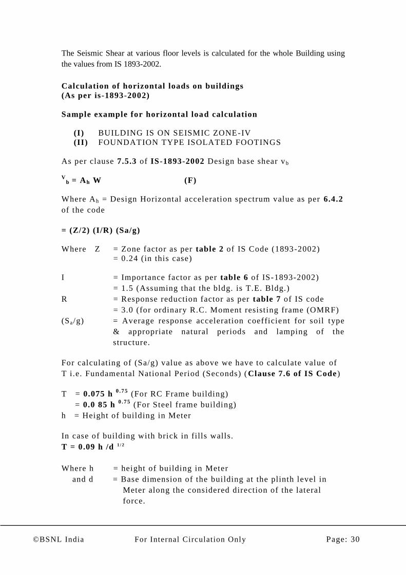
The Seismic Shear at various floor levels is calculated for the whole Building using
the values from IS 1893-2002.
Calculation of horizontal loads on buildings
(As per is-1893-2002)
Sample example for horizontal load calculation
(I) BUILDING IS ON SEISMIC ZONE-IV
(II) FOUNDATION TYPE ISOLATED FOOTINGS
As per clause 7.5.3 of IS-1893-2002 Design base shear v b
V
b = Ah W (F)
Where Ah = Design Horizontal acceleration spectrum value as per 6.4.2
of the code
= (Z/2) (I/R) (Sa/g)
Where Z = Zone factor as per table 2 of IS Code (1893-2002)
= 0.24 (in this case)
I = Importance factor as per table 6 of IS-1893-2002)
= 1.5 (Assuming that the bldg. is T.E. Bldg.)
R = Response reduction factor as per table 7 of IS code
= 3.0 (for ordinary R.C. Moment resist ing frame (OMRF)
(Sa/g) = Average response acceleration coefficient for soil type
& appropriate natural periods and lamping of the
structure.
For calculating of (Sa/g) value as above we have to calculate value of
T i.e. Fundamental National Period (Seconds) ( Clause 7.6 of IS Code)
T = 0.075 h 0 .7 5
(For RC Frame building)
= 0.0 85 h 0 .7 5
(For Steel frame building)
h = Height of building in Meter
In case of building with brick in fills walls.
T = 0.09 h /d 1 / 2
Where h = height of building in Meter
and d = Base dimension of the building at the plinth level in
Meter along the considered direction of the lateral
force.

©BSNL India For Internal Circulation Only Page: 31
Value of (Sa/g) is to be read from fig 2 on page 16 of IS Code
depending upon Soil condition & Fundamental Natural period T.
Or the value of (Sa/g) may be calculated on the basis of
Following.
Formulas:-
(i) For rocky, or hard soil sites
(Sa/g) = 1+15 T if 0.00≤T≤ 0.10
= 2.50 if 0.10≤T≤ 0.40
=1.00/T if 0.40≤T≤ 4.00
(ii) For medium soil sites
(Sa/g) = 1+15 T if 0.00≤T≤ 0.10
= 2.5 0 if 0.10≤T≤0.55
= 1.36/T if 0.55≤T≤ 4.00
(iii) For soft soil si tes
(Sa/g) = 1+15 T if 0.00≤T≤<0.10
= 2.50 if 0.10≤T≤0.67
=1.67/T i f 0.67≤T≤ 4.00
W= Seismic weight of the building as per clause 7.4.2 of the code .

©BSNL India For Internal Circulation Only Page: 32
A
B
C
2 b
ays @
7.5
m C
/C
TYPICAL FLOOR PLAN
Bldg. is three storey with Each
storey of 5.0m height
4 bays @ 4.0 m C/C

©BSNL India For Internal Circulation Only Page: 33
164.9
157.99
47.01
Frame with EQ Loads
©BSNL India For Internal Circulation Only Page: 34
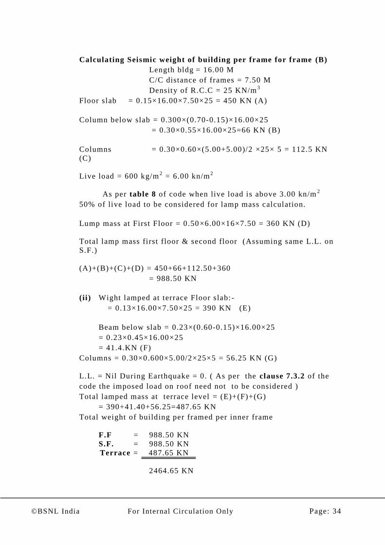
Calculating Seismic weight of building per frame for frame (B)
Length bldg = 16.00 M
C/C distance of frames = 7.50 M
Density of R.C.C = 25 KN/m3
Floor slab = 0.15×16.00×7.50×25 = 450 KN (A)
Column below slab = 0.300×(0.70-0.15)×16.00×25
= 0.30×0.55×16.00×25=66 KN (B)
Columns = 0.30×0.60×(5.00+5.00)/2 ×25× 5 = 112.5 KN
(C)
Live load = 600 kg/m2 = 6.00 kn/m
2
As per table 8 of code when live load is above 3.00 kn/m2
50% of live load to be considered for lamp mass calculation.
Lump mass at First Floor = 0.50×6.00×16×7.50 = 360 KN (D)
Total lamp mass first floor & second floor (Assuming same L.L. on
S.F.)
(A)+(B)+(C)+(D) = 450+66+112.50+360
= 988.50 KN
(ii) Wight lamped at terrace Floor slab: -
= 0.13×16.00×7.50×25 = 390 KN (E)
Beam below slab = 0.23×(0.60-0.15)×16.00×25
= 0.23×0.45×16.00×25
= 41.4.KN (F)
Columns = 0.30×0.600×5.00/2×25×5 = 56.25 KN (G)
L.L. = Nil During Earthquake = 0. ( As per the clause 7.3.2 of the
code the imposed load on roof need not to be considered )
Total lamped mass at terrace level = (E)+(F)+(G)
= 390+41.40+56.25=487.65 KN
Total weight of building per framed per inner frame
F.F = 988.50 KN
S.F. = 988.50 KN
Terrace = 487.65 KN
2464.65 KN
LL-- FFRRAAMMEE
©BSNL India For Internal Circulation Only Page: 35
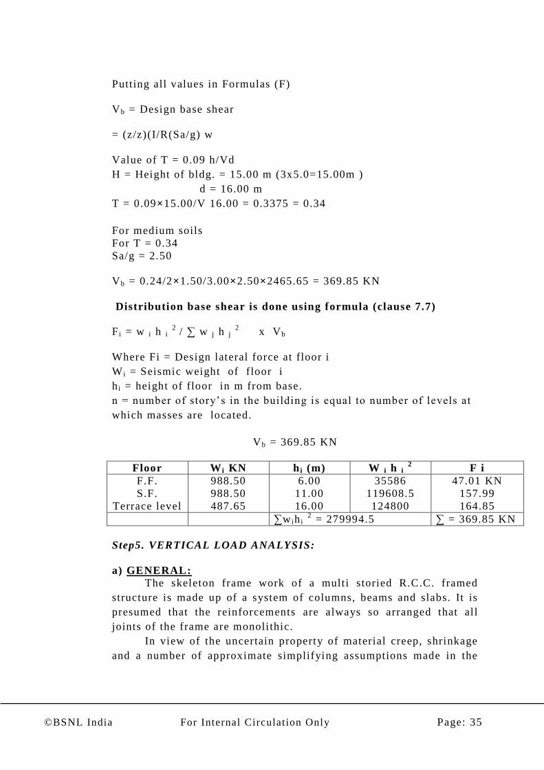
Putting all values in Formulas (F)
Vb = Design base shear
= (z/z)(I/R(Sa/g) w
Value of T = 0.09 h/Vd
H = Height of bldg. = 15.00 m (3x5.0=15.00m )
d = 16.00 m
T = 0.09×15.00/V 16.00 = 0.3375 = 0.34
For medium soils
For T = 0.34
Sa/g = 2.50
Vb = 0.24/2×1.50/3.00×2.50×2465.65 = 369.85 KN
Distribution base shear is done using formula (clause 7.7)
F i = w i h i 2
/ ∑ w j h j 2
x Vb
Where Fi = Design lateral force at floor i
W i = Seismic weight of floor i
h i = height of floor in m from base.
n = number of story’s in the building is equal to number of levels at
which masses are located.
Vb = 369.85 KN
Floor W i KN h i (m) W i h i 2 F i
F.F.
S.F.
Terrace level
988.50
988.50
487.65
6.00
11.00
16.00
35586
119608.5
124800
47.01 KN
157.99
164.85
∑w ih i 2 = 279994.5 ∑ = 369.85 KN
Step5. VERTICAL LOAD ANALYSIS:
a) GENERAL:
The skeleton frame work of a multi storied R.C.C. framed
structure is made up of a system of columns, beams and slabs. It is
presumed that the reinforcements are always so arranged that al l
joints of the frame are monolithic.
In view of the uncertain property of material creep, shrinkage
and a number of approximate simplifying assumptions made in the

©BSNL India For Internal Circulation Only Page: 36
detailed analysis of multi storied framed structures (such as
conditions of end restraints etc.) it is considered sufficient to obtain
reasonable accuracy of analysis for the design of structure. If the
normal moment distribution is applied to all joints, the work
involved is enormous. However with certain assumptio ns, it is
possible to analyze the frames and get results which will be adequate
for design purposes.
To simplify analysis the three dimensional multistoried R.C.C.
framed structure are considered as combinations of planer framed in
two directions. It is assumed that each of these planer frames act
independently of the frames.
Procedure for Frame analysis for calculation of moments in
Columns & beams:
Step(i): First , the load from slab (including Live load & Dead Load)
is transferred on to the adjoining beams using formulas
given below|:-
For computation of Bending Moments in beams , an equivalent
uniformly distributed load per linear meter of beam may be taken as
:
Equivalent u.d.l. on short beam of slab panel = w B/3.0
Equivalent u.d.l. on long beam of slab panel = w B/6 x [ 3 -
(B/L)2
]
where w is the total load on the slab panel in Kn/Sqm & L & B are
long span & short spans of slab panel respectively.
Step(ii): Over this load, the weight of wall (if any), self weight of
beam etc. are added to get the load on beam (in running
Meter).
Step(iii):The load (in running Meter) on each beam is calculated as
in Step 1 & Step 2.
Step(iv):Step (i) to Step (ii i) is repeated for each floor
Step(v):Then these loads are used as u.d.l on a particular frame for
analysis by moment distribution method as described in the next
section.

©BSNL India For Internal Circulation Only Page: 37
b) METHOD OF ANALYSIS:
Analysis of large framed structures beams too Cumbersome
with the classical method of structure analysis such a Clapeyron’s
theorem of three moments, Castingiliano’s therefore of least work,
Poison’s method of virtual work etc. Therefore, it become necessa ry
to evolve simpler methods.
Some of these are: -
a.) Hardy cross method of moment distribution.
b.) Kani’s method of iteration.
c) HARDY CROSS METHOD OF MOMENT DISTRIBUTION:
In this method, the ‘balancing’ and ‘carry-over’ constitute one
cycle and it has been found the ‘carry-over’ values converge fast
enough to become quite insignificant after four cycle of operation. it
is, therefore, often adequate to stop the computation after four
cycles.
The frame is analyzed by this method either:
i . Floor-wise assuming the columns to be fixed for ends.
or
i i . Taking the frame as a whole. The whole frame analysis can
be carried out for several alternative loading arrangements
for obtaining maximum positive and negative bending
moment. Generally frames are analyzed floor-wise for the
worst conditions of loading.
The method is described in the following steps .
Step1: Calculate the stiffness of all members. Enter them in the
calculation scheme.
Step2: Calculated the distribution factor at all joints from the
stiffness. Enter them in the calculation scheme.
Step3: Look the joints and calculate the fixed -end moments.
Enter them in the calculation scheme.

©BSNL India For Internal Circulation Only Page: 38
Step4: Unlock the joint one by one by applying imaginary external
moments at each joint which nullifier the unbalanced moment at the joint.
Distribute the imaginary external moment among all members
Meeting at the joint in proportion to their relative
stiffness and enter these value in the scheme. This
operation is called balancing.
Step5: Enter the carry-over moments at the far in the scheme.
Step6: Repeat steps 4 & 5, ti ll the carry-over moments
become insignificant .
Step7: Balance the unbalanced moment obtained from the last
carry-over operation.
Step8: Add the init ial fixed-end moments, balancing moments
and carry-over moments to get the final end moments in
beam & columns.
A sample of moment distribution method is shown on next two
pages.

©BSNL India For Internal Circulation Only Page: 39
CALCULATION OF DISTRIBUTION FACTOR FOR FRAME ANALYSIS
S.NO. JOINT MEMBE
R Size in Cm
Mo ment o f
Iner t i a
Cm4 ( I )
Leng
th of
mem
ber
Cm
K=I /L Su m K D.F .
1
B D
A-I I I
Right
beam 30 45 227812.50 600 379 .69
1030 .58
0 .37
Lo wer
Col . 30 45 227812.50 350 650 .89 0 .63
2
B-II I
Left
beam 30 45 227812.50 600 379 .69
1802 .01
0 .21
Right
beam 30 60 540000.00 700 771 .43 0 .43
Lo wer
Col . 30 45 227812.50 350 650 .89 0 .36
3 C-II I
Left
beam 30 60 540000.00 700 771 .43
1422 .32
0 .54
Lo wer
Col . 30 45 227812.50 350 650 .89 0 .46
4
A-II
Upper
co l . 30 45 227812.50 350 650 .89
1681 .47
0 .39
Right
beam 30 45 227812.50 600 379 .69 0 .23
Lo wer
Col . 30 45 227812.50 350 650 .89 0 .39
5
B-I I
Left
beam 30 60 540000.00 600 900 .00
2973 .21
0 .30
Upper
co l . 30 45 227812.50 350 650 .89 0 .22
Right
beam 30 60 540000.00 700 771 .43 0 .26
Lo wer
Col . 30 45 227812.50 350 650 .89 0 .22
6
C-I I
Left
beam 30 60 540000.00 700 771 .43
2073 .21
0 .37
Upper
co l . 30 45 227812.50 350 650 .89 0 .31
Lo wer
Col . 30 45 227812.50 350 650 .89 0 .31
7
A-I
Upper
co l . 30 45 227812.50 350 650 .89
1572 .99
0 .41
Right
beam 30 45 227812.50 600 379 .69 0 .24
Lo wer
Col . 30 45 227812.50 420 542 .41 0 .34
8
B-I
Left
beam 30 45 227812.50 600 379 .69
2344 .42
0 .16
Upper
co l . 30 45 227812.50 350 650 .89 0 .28
Right
beam 30 60 540000.00 700 771 .43 0 .33
Lo wer
Col . 30 45 227812.50 420 542 .41 0 .23
9
C-I
Left
beam 30 60 540000.00 700 771 .43
1964 .73
0 .39
Upper
co l . 30 45 227812.50 350 650 .89 0 .33
Lo wer
Col . 30 45 227812.50 420 542 .41 0 .28

©BSNL India For Internal Circulation Only Page: 40
FRME ANALYSIS BY MOMENT DISTRIBUTION METHOD
I I I
U.d. l .
28 6 .00
U.D.L
24 7.00
0 .63 0.37 30X45 0.21 0.43 0.36 30X60 0 .54 0.46
0 -84.00 Int .FEM 84.00 0 -98.00 Int .FEM 98.00 0
bal . 52.92 31.08 2 .94 6.02 5.04 -52.92 -45.08
C.O. 14.63 1.47 15.54 0.74 -26.46 2 .52 -12.66
BAL -10.14 -5 .96 2 .14 11.06 3.66 5 .48 4.66
Total 57.41 -57.41 104.62 17.82
-
115.76 53.08 -53.08
Total 38.28 4 .06 -34.87
BAL -17.43 BAL -0.42 BAL 12.99
C.O. 26.46 C.O. 3 .01 C.O. -22.54
29.25 1 .47 -25.32
0 0 0
0 .39 0 .22 0 .31
II 25 6 .00 20 7 .00
0 .39 0.23 0 .3 0 .22 0.26 0 .37 0.31
0 -75.00 Int .FEM 75.00 0 -81.67 Int .FEM 81.67 0
29.25 17.25 2 1 .47 1.73 -30.22 -25.32
C.O. 17.22 1 8 .63 5.39 -15.11 0 .87 -20.22
BAL -17.43 -10.28 -0 .58 -0 .42 -0 .5 15.5 12.99
29.04 -67.03 85.05 6.44 -95.55 67.82 -32.55
Total 41.81 15.18 -51.01
BAL -7.26 3 .66 2 .08
C.O. 14.63 0 .74 -12.66
34.44 10.78 -40.43
0 0 0
0 .41 0 .28 0 .33
I 28 6 .00 30 7 .00
0 .34 0.24 0 .16 0.23 0.33 0 .39 0.28
0 -84.00 Int .FEM 84.00 0
-
122.50 Int .FEM 122.50 0
28.56 20.16 6 .16 8.86 12.71 -47.78 -34.3
C.O. 0 3 .08 10.08 0 -23.89 6 .36 0
BAL -6.02 -4 .25 2 .09 3.01 4.31 2 .46 1.76
22.54 -65.01 102.33 11.87
-
129.37 83.54 -32.54
A B C
©BSNL India For Internal Circulation Only Page: 41
Step6. HORIZONTAL LOAD ANALYSIS:-
Frame analysis for horizontal loads calculated in step 4 is carried
out by using : -
(a)Approximate Method: -
i) Canti lever method.
ii) Portal method.
Approximate methods are used for preliminary designs only. For
final design we may use exact method i.e (i) Slope deflection or
matrix methods (ii) Factor method.
We will not discuss these methods in detail as now modern
computer package as STAAD PRO is available for analysis.
Step7: DESIGN OF COULMN,FOUNDATIONS, BEAMS &
SLABS:
After load calculation & anal ysis for vertical & horizontal
loads, design of Columns ,Foundations, Beams, Slabs and are to be
carried out as per the various cl auses of IS codes, IS 456-2000,
IS:1893-2002, IS:13920-1993 etc.
The Design of Column, Foundation, Beams and Slabs are discussed
in details in following section.
A. Design of columns: - With the knowledge of (i) Vertical
load (ii) Moments due to horizontal loads on either axis;(iii)
Moments due to vertical loads on either axis, acting on each column,
at all floor levels of the building , columns are designed by charts of
SP-16(Design Aids) with a load factor of 1.5 for vert ical load effect
and with a load factor of 1.2 for the combined effects of the vertical
and the horizontal loads. The step confirms the size of columns
assumed in the architectural drawings. The design of each column is
carried out from the top of foundation to the roof, varying t he
amount of steel reinforcement for suitable groups for ease in design.
Further, slenderness effects in each storey are considered for each
column group.
Important Considerations in design of Columns: -
(i)Effective height of column :- The effective height of a column is
defined as the height between the points of contra flexure of the
buckled column. For effective column height refer table 28
(Annexure E) of IS: 456-2000.

©BSNL India For Internal Circulation Only Page: 42
For framed structure effective height of column depends
upon relative stiffness of the column & various beams framing into
the column at its two ends. (Refer Annexure E of IS: 456 -2000.)
(ii)Unsupported Length : - The unsupported length l , of a
compression member shall be taken as the clear distance between
end restraints except that: -
In beam & slab construction, i t shall be the clear distance
between the floor & under side of the shallower beam framing into
the columns in each direction at the next higher floor level.
(iii) Slenderness l imits for columns : - The unsupported length
between end restraints shall not exceed 60 times the least lateral
dimension of a column.
(iv) Minimum Eccentricity : - All columns shall be designed for
minimum eccentricity equal to unsupported length of column/500
plus least lateral dimension/30, subject to a minimum of 20 mm.
Or emin ≥ l/500+ D/30 ≥ 20 mm
Where l= unsupported length of column in mm.
D=Lateral dimension of column in the direction under
consideration in mm.
(v)Design Approach : - The design of column is complex since it is
subjected to axial loads & moments which may very independently.
Column design required:-
I. Determination of the cross sectional dimension.
II. The area of longitudinal steel & its distribution.
III. Transverse steel .
The maximum axial load & moments acting along the length of
the column are considered for the design of the column section
either by the working stress method or limit state method.
The transverse reinforcement is provided to impart effective
lateral support against buckling to every longitudinal bar. It is either
in the form of circular rings of polygonal links (late ral ties).

©BSNL India For Internal Circulation Only Page: 43

©BSNL India For Internal Circulation Only Page: 44
B. Design of foundations: - With the knowledge of the column loads
and moments at base and the soil data, foundations for columns are
designed
The following is a list of different types of foundations in
order to preference with a view to ec onomy: (i) Individual footings
(ii) Combination of individual and combined footings (i ii) Strip
footings with retaining wall acting as strip beam wherever
applicable; (iv) Raft foundations of the types (a) Slab (b) beam -slab.
The brick wall footings are also designed at this stage. Often,
plinth beams are provided to support brick walls and also to act as
earthquake ties in each principal direction. Plinth beams, retaining
wall if any, are also designed at this stage, being considered as part
of foundations.
Important Considerations in design of Foundations: -
a) Introduction: - Foundations are structural elements that
transfer loads from the building or individual column to the earth.
If these loads are to be properly transmitted, foundations must be
designed to prevent excessive settlement or rotation, to minimize
differential settlement and to provide adequate safety against
sliding and over turning.
b) Depth of foundation: -
Depth of foundation below ground level may be obtained by using
Rankine's formula
2
p 1 – Sin Ø
h = - - - - - - - - - - - - - - -
γ 1 + Sin Ø
Where
h = Minimum depth of foundation
p = Gross bearing capacity
γ = Density of soil
Ø = Angle of Repose of soil

©BSNL India For Internal Circulation Only Page: 45
c) Recommendations of IS 456 -2000, limit state design, bending,
shear, cracking & development
i) To determine the area required for proper transfer of total load on the soil,
the total load (the combination of dead, live and any other load without
multiplying it with any load factor) need be considered.
Total Load including Self Weight
Plan Area of footing = -------------------------------------
Allowable bearing capacity of soil
i i) IS 1904 – 1978, Code of Practice for Structural Safety of
Buildings : shallow foundation, shall govern the general
details .
iii) Thickness of the edge of footing: -(Reference clause
34.1.2) The thickness at the edge shall not be less than 15 cm for
footing on soils.
iv) Dimension of pedestal: -
In the case of plain Cement Concrete pedestals, the angle between the plane
passing through the bottom edge of the pedestal and the corresponding junction
edge of the column with pedestal and the horizontal plane shall be governed
by the expression.
100 qo
Tan α (should not be less than) 0.9 x ----------- + 1
Fck
Where
qo = Calculated maximum bearing pressure at the base
of the
pedestal/footing in N/mm2
fck = Characteristic strength of concrete at 28 days in
N/mm2

©BSNL India For Internal Circulation Only Page: 46
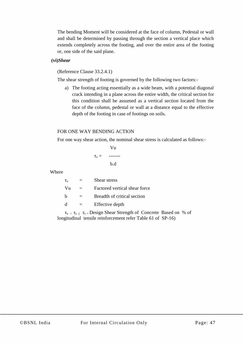
(v) Bending Moment
(Reference Clauses- 34.2.3.1 & 34.2.3.2)
ISOLATED COLUMN FOOTING
FACE OF
PEDESTA
L
PLAIN
CONCRETE
PEDESTAL
α
Column
X Y
X Y
COLUMN
PEDESTAL BASE
FACE OF
COLUMN
©BSNL India For Internal Circulation Only Page: 47
The bending Moment will be considered at the face of column, Pedestal or wall
and shall be determined by passing through the section a vertical place which
extends completely across the footing, and over the entire area of the footing
or, one side of the said plane.
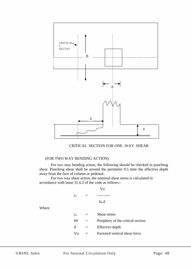
(vi)Shear
(Reference Clause 33.2.4.1)
The shear strength of footing is governed by the following two factors:-
a) The footing acting essentially as a wide beam, with a potential diagonal
crack intending in a plane across the entire width, the critical section for
this condition shall be assumed as a vertical section located from the
face of the column, pedestal or wall at a distance equal to the effective
depth of the footing in case of footings on soils.
FOR ONE WAY BENDING ACTION
For one way shear action, the nominal shear stress is calculated as follows:-
Vu
τv = -------
b.d
Where
τv = Shear stress
Vu = Factored vertical shear force
b = Breadth of critical section
d = Effective depth
τv < τc ( τc = Design Shear Strength of Concrete Based on % of
longitudinal tensile reinforcement refer Table 61 of SP-16)
©BSNL India For Internal Circulation Only Page: 48
CRITICAL SECTION FOR ONE -WAY SHEAR
(FOR TWO WAY BENDING ACTION)
For two may bending action, the following should be checked in punching
shear. Punching shear shall be around the perimeter 0.5 time the effective depth
away from the face of column or pedestal.
For two way shear action, the nominal shear stress is calculated in
accordance with lause 31.6.2 of the code as follows:-
Vu
τv = ----------
b0.d
Where
τv = Shear stress
b0 = Periphery of the critical section
d = Effective depth
Vu = Factored vertical shear force
B
A
CR IT IC A
L SECT IO
N
d
d
©BSNL India For Internal Circulation Only Page: 49
When shear reinforcement is not provided, the nominal shear stress at the
critical section should not exceed [Ks. τc]
Where
Ks = 0.5 + Bc (But not greater than 1)
Short dimension of column or pedestal
Bc = ----------------------------------------------------
Long dimension of column or pedestal
τc = 0.25 fek N/mm2
Note:-It is general practice to make the base deep enough so that shear
reinforcement is not required.
(vii)Development Length
(Reference Clause 34.2.4.3)
The critical section for checking the development length in a footing
shall be assumed at the same planes as those described for bending moment
in clause 34.2.3 of code (as discussed 4.5 of the handout) and also at all
other vertical planes where abrupt changes of section occur.
(viii) Reinforcement:- The Min % of steel in footing slab should be 0.12%
& max spacing should not be more than 3 times effective depth or
450 mm whichever is less. (Reference Clause 34.3)
Only tensile reinforcement is normally provided. The total
reinforcement shall be laid down uniformly in case of square footings. For
rectangular footings, there shall be a central band, equal to the width of the
footings. The reinforcement in the central band shall be provided in
accordance with the following equation.
Reinforcement in central Band width 2
-------------------------------------------------- = ------
Total reinforcement in short direction B + 1
Where
Long side of footing
B = ---------------------------
Short side of footing

©BSNL India For Internal Circulation Only Page: 50
(ix)Transfer of Load at the Base of Column
(Reference Clause 34.4)
The compressive stress in concrete at the base of column or pedestal shall
be transferred by bearing to the top of supporting pedestal or footing.
The bearing pressure on the loaded area shall not exceed the permissible
bearing stress in direct
A1
Compression multiplied by a value equal to ------
A2
but not greater than 2
Where
A1 = Supporting area for bearing of footing, which is sloped or
stepped footing may be taken as the area of the lower base
of the largest frustum of a pyramid or cone contained wholly
with in the footing and having for its upper base, the area
actually loaded and having side slope of one vertical to two
horizontal.
A2 = Loaded area at the column base.
For limit state method of design, the permissible bearing stress shall be = 45 fek
4.91 If the permissible bearing stress is exceeded either in column concrete or in
footing concrete, reinforcement must be provided for developing the excess
force. The reinforcement may be provided either by extending the longitudinal
bars into the footing or by providing dowels in accordance with the code as
give in the following:-
1) Minimum area of extended longitudinal bars or dowels must be 0.5% of
cross sectional area of the supported column or pedestal.
2) A minimum of four bars must be provided.
3) If dowels are used their diameter should not exceed the diameter of the
column bars by more than 3 mm.
4) Enough development length should be provided to transfer the
compression or tension to the supporting member.
5) Column bars of diameter larger than 36 mm, in compression only can
be dowelled at the footing with bars of smaller diameters. Te dowel
must extend into the column a distance equal to the development length
of the column bar. At the same time, the dowel must extend vertically
into the footing a distance equal to the development length of the
dowel.
©BSNL India For Internal Circulation Only Page: 51
C. Design of Floor slabs:-. Design of floor slabs and beams is taken up with the First Floor & upwards .The slabs are
designed as one-way or two-way panels, taking the edge conditions of the supporting edges in to account, with the
loading already decided as per functional use of slab panel.
The design of floor slab is carried out as per clause 24.4 & 37.1.2 & Annexure D of IS: 456-2000. The
Bending moment coefficients are to be taken from table- 26 of the code depending upon the support condition &
bending moment calculated & reinforcement steel may be calculated from the charts of SP-16. The slab design for
particular floor may be done in tabular form as shown below.

©BSNL India For Internal Circulation Only Page: 52
SLAB DESIGN
Name of project: -
Level of s lab
Sla
b
ID
Edge
condi t i
on
Total
load in
KN/Sq
.m w
Shor
t
span
lx
m
long
spa
n
l y
m
ly/
lx
1 .5
*w* lx
*lx
s lab
th ic
knes
s in
mm
Shor t span Mo ment KN -M
Stee l
in
shor t
span
Lon g sp an mo ment KN-M
Stee l
in
long
span
αx
(+)
Αx
( - )
mux
+
mux
-
Stee
l
Αy
(+) αy( - )
muy
+
muy
- Stee l
1 2 3 4 5 6 7 8 9 1 0 11=
7 x 9
12=
7
x10
13 1 4 15
16=
7
x14
17=
7
x15
1 8
S1
Two
Adj .
Edge.
Discon
t.
(Case
No.4)
8 .50 3 .5
0
5.2
5
1 .
5
156.8
0 120
0.05
6
0.07
5 8 .78
11.7
6
0 .03
5
0.047
5 .49 7 .37
S2

©BSNL India For Internal Circulation Only Page: 53
Method of calculation of steel from Tables of SP-16 for slab design
Determine the main reinforcement required for a slab with the following data:
Factored moment Mu 9.60 kN.mper Metre width
Depth of slab 10 cm
Concrete mix M 20
Characteristic strength a) 415 N/mm2
METHOD OF REFERRING TO TABLES FOR SLABS
Referring to table 35 (for fck=20 & fy = 415 N/mm2), directly we get the following
reinforcement for a moment of resistance of 9.60 kN.m per Metre width:
8 mm dia at 13 cm spacing
or 10 mm dia at 210 cm spacing
Reinforcement given in the table is based on a cover of 15 mm or bar diameter which-
ever is greater.
Check for Deflection:-Slab is also checked for control of Deflection as per clause
23.2.1, 24.1 & Fig 4. of the IS:456-2000.
D. Design of floor Beams:-. The beams are designed as continuous beams,
monolithic with reinforced concrete columns with their far ends assumed fixed. The
variation in the live load position is taken into account by following the two-cycle
moment distribution. the moments are applied a face correction to reduce them to the
face of the members. The moments due to horizontal loads are added to the above
moments. Each section of the beam is designed for load factor of 1.5 for vertical load
effect and with a load factor of 1.2 for the combined effects of the vertical and the
horizontal loads.
The effect of the shear due to vertical and horizontal loads is also similarly
taken care of. It may be noted that the shear component due to wind or earthquake
may be significant and it may affect the size and the range of shear stirrups. Bent- up
bars are not effective for earthquake shear due to its alternating nature. The beam
design can be easily done by a computer program which will give reinforcement at
various critical sections along the length of the beam and also shear stirrups required
it saves considerable time and labour of a designer.
In manual method span of a beam is generally designed at three sections i.e
at two supports & at Mid span. The each section is designed for factored Moment,
Shear & equivalent shear for Torsion if any at a section.
Two examples of beam design are given below illustrating calculation of
steel reinforcement with help of SP-16.

©BSNL India For Internal Circulation Only Page: 54
Example1.Singly Reinforced Beam
Determine the main tension reinforcement required for a
rectangular beam section with the following data:
Size of beam 30 X 60 cm
Concrete mix M 20
Characteristic strength 415 N/mm2 of reinforcement
Factored moment 170 kN.m
Assuming 20 mm dia bars with 25 mm clear cover,
Effective depth= 600 – 25 – 20/2 = 565 mm
From Table D for fy = 415 N/ mm2
and fck = 20 N/mm2
Mu, l im/bd2
= 2.76 N/ mm2
= 2.76/1000 X (1000)2
= 2.76 X 10³
kN/m2
Mu, l im = 2.76 X 10³ bd
2
= 2.76 X 103
X 0.300 X0.565X0.565
= 264.32 kN.m
Actual moment of 170 kN.m is less than M u, l im. The section is therefore
to be designed as a singly reinforced (under -reinforced) rectangular
section.
Referring to table 2 of SP-16 we have to calculate Mu/bd2
Mu/bd2
= 170 x106/(300x 565 x565) = 1.78
From Table 2. p t =0.556
A s t=0.556 x 300x 565/100 =942.42mm2=9.42 cm
2
Example2.Doubly Reinforced Beam (i)Determine the main reinforcements required for a rectangular
with the following data :
Size of beam 30×60cm
Concrete mix M 20
Characteristic strength of 415/Nmm2
Reinforcement
Factored moment 320Kn.m
Assuming 20 mm dia bars with 25 mm clear cover,
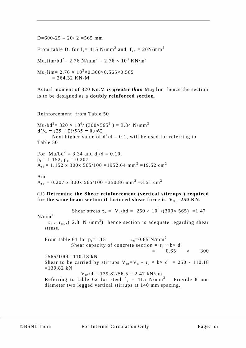
©BSNL India For Internal Circulation Only Page: 55
D=600-25 – 20/ 2 =565 mm
From table D, for f y= 415 N/mm2 and fck = 20N/mm
2
Mu2 lim/bd2= 2.76 N/mm
2 = 2.76 × 10
3 KN/m
2
Mu2 lim= 2.76 × 103×0.300×0.565×0.565
= 264.32 KN-M
Actual moment of 320 Kn.M is greater than Mu2 lim hence the section
is to be designed as a doubly reinforced section .
Reinforcement from Table 50
Mu/bd2= 320 × 10
6/ (300×565
2 ) = 3.34 N/mm
2
Next higher value of d1/d = 0.1, will be used for referring to
Table 50
For Mu/bd2 = 3.34 and d
’/d = 0.10,
p t = 1.152, pc = 0.207
As t = 1.152 x 300x 565/100 =1952.64 mm2 =19.52 cm
2
And
Asc = 0.207 x 300x 565/100 =350.86 mm2 =3.51 cm
2
(ii) Determine the Shear reinforcement (vertical stirrups ) required
for the same beam section if factored shear force is V u =250 KN.
Shear stress τ v = Vu /bd = 250 × 103
/(300× 565) =1.47
N/mm2
τv < τmax( 2.8 N /mm2) hence section is adequate regarding shear
stress.
From table 61 for p t=1.15 τc=0.65 N/mm2
Shear capacity of concrete section = τc × b× d
= 0.65 × 300
×565/1000=110.18 kN
Shear to be carried by stirrups V u s=Vu - τc × b× d = 250 - 110.18
=139.82 kN
Vu s/d = 139.82/56.5 = 2.47 kN/cm
Referring to table 62 for steel f y = 415 N/mm2 Provide 8 mm
diameter two legged vertical stirrups at 140 mm spacing.

©BSNL India For Internal Circulation Only Page: 56
TABLES
FOR
DESIGN
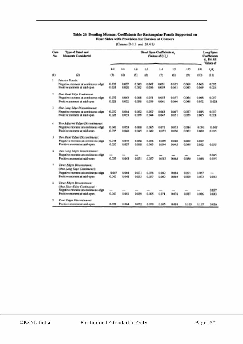
©BSNL India For Internal Circulation Only Page: 57

©BSNL India For Internal Circulation Only Page: 58

©BSNL India For Internal Circulation Only Page: 59

©BSNL India For Internal Circulation Only Page: 60

©BSNL India For Internal Circulation Only Page: 61

©BSNL India For Internal Circulation Only Page: 62
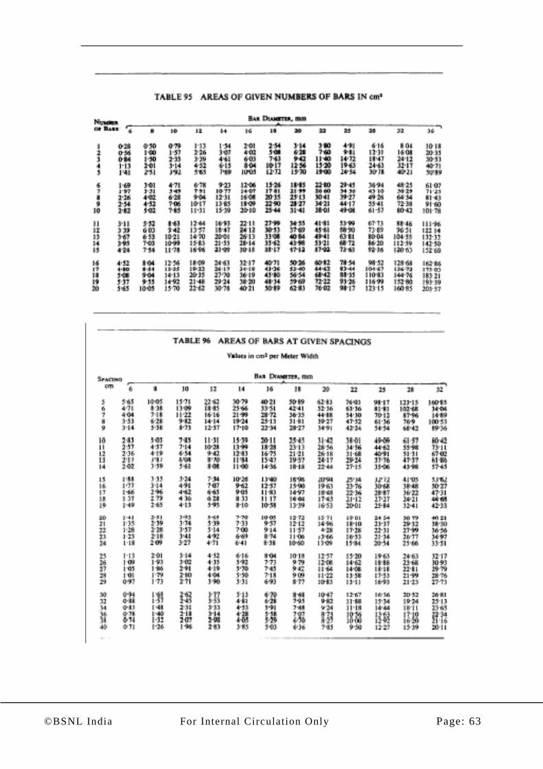
©BSNL India For Internal Circulation Only Page: 63

©BSNL India For Internal Circulation Only Page: 64

©BSNL India For Internal Circulation Only Page: 65

©BSNL India For Internal Circulation Only Page: 66

©BSNL India For Internal Circulation Only Page: 67

©BSNL India For Internal Circulation Only Page: 68
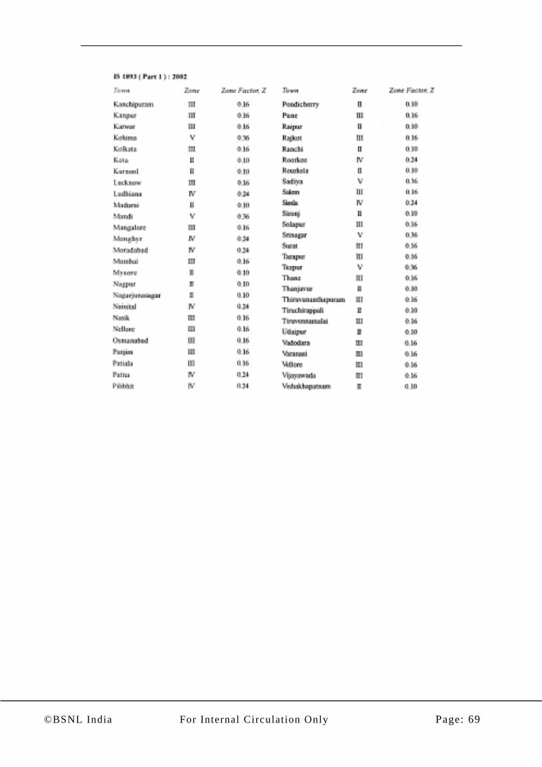
©BSNL India For Internal Circulation Only Page: 69

©BSNL India For Internal Circulation Only Page: 70
DETAILING AS PER IS 13920

©BSNL India For Internal Circulation Only Page: 71
HOOP SPACING
HOOP SPACING< d/4 and 8 db
B = BREADTH OF BEAMdb = DIAMETER OF LONGITUDINAL BAR
2d
d
2d
db
50 m max 50 m max
MIN 2 BARS FOR FULL LENGTHALONG TOP AND BOTTOM FACEAS > MIN. BdAS < MAX Bd
> d /2
BEAM REINFORCEMENT37
Questions:-
1. Which are the important BIS Codes/handouts used for structural
design of RCC buildings?
2. In which seismic zones provisions of IS 13920 is to be adopted
for all reinforced concrete structures?
3. (a) What are the basic values of span to effective depth ratios for
beams as per IS 456 for span upto 10meter for –
(i) Cantilever
(ii) Simply supported
(iii) Continuous
(b) What are the basic values of span to overall depth ratios for
two-way slabs upto 3.5 m span & with Fe415 steel reinforcement
and loading class upto 3KN/m2?
4. What are the provisions of IS 456 for nominal cover to meet
durability requirements? As per IS 456 how much minimum
cover should be provided for –
a) Column b) Footing
5. (a) What are the minimum reinforcement provision of IS 456 for
beams in respect of:
(i) Tension reinforcement
(ii) Shear reinforcement

©BSNL India For Internal Circulation Only Page: 72
(b) What are the IS 456 provisions for maximum reinforcement
in beams for: -
(i) Compression reinforcement
(ii) Tension reinforcement
6. What is the maximum permissible spacing for shear
reinforcement in beams? Explain IS 456 provisions for side face
reinforcement in beams.
7. How much minimum reinforcement must be provided in slabs?
8. As per IS1893 give formulae for calculating –
a) Design Base Shear (Vb)
b) Design Horizontal acceleration (Ah)
9. Give formulae for calculating t ime period as per IS1893 for –
a) RCC Frame Building b) RCC Building Brick in fill walls
10. How vertical loads on columns are calculated? Give names of
simpler methods of analysis of structures.
11. What is the minimum eccentricity for which all columns should
be designed? List out minimum and maximum longitudinal
reinforcement required to be provided in columns? Give in
brief provisions for maximum spacing of lateral ties in a
column?
12. What are the critical sections in isolated footing design for the
following:-
a) Bending moment
b) One way shear
c) Two way shear
13. How many minimum longitudinal reinforcement bars should be
provided in: -
a) Circular column
b) Rectangular column
14. What is the minimum diameter bar that can be used in
longitudinal reinforcement in column?
-----------------