chapter 2 work and heat - michigan state universitylira/liranotes/chap02.pdf · chapter 2 work and...
TRANSCRIPT

1
Chapter 2Work and Heat
•EL 2.1-2.4 Work, Reversibility•EL 2.5 Path Properties•EL 2.6 Heat Flow•EL 2.7 Closed System
(FR 7.0-7.3) Energy Balance•EL 2.8 Open, Steady-State
(FR 7.4) Balance•EL 2.10 Enthalpy, Heat Capacities
(FR 8.1-8.3b) Latent Heats(FR 8.4a,c)
•EL 2.11, 2.12 Process Equipment•EL 2.13 (FR 7.6) Strategies
{

2
A theory is the more impressive the greater the simplicity of its premises is, the more different kinds of things it relates, and the more extended is its area of applicability. Therefore the deep impression which classical thermodynamics made upon me.
Albert Einstein
The first law of thermodynamics - energy is conserved. Relates heat, work, mass flow across boundaries to U, KE, PE of the system.

3
The Mass Balance
where
rate of massaccumulation withinsystem boundaries
rate of mass flowinto system
rate of mass flowout of system
–=
m = m - min
inlets
out
outlets Â
m· dmdt-------=

4
= absolute value of mass flow rateentering and leaving, respectively
We may also write
dmin and dmout > 0.
, m min out
dm dmin
inlets dmout
outlets–=

5
Work•Expansion/Contraction Work•Shaft Work•Flow work
Expansion/Contraction Work (System must change size)
dW = Fapplieddx = -Fsystemdx
P = F/A F = P·A
W P A dx P dVEC = − − zz =

6
if lower T,P dropsrigid

7
2.2 Shaft Work
Work done in pushing and or stirring system.•Usually involves a pump, turbine, or stirring shaft
The essential feature of shaft work is that work isbeing added or removed without a change in volumeof the system. (Fluid may change molar volume as itpasses through the system).2.3 Flow Work
W· flowin
Fx· = PAx· PV· PVm· in= = =
8
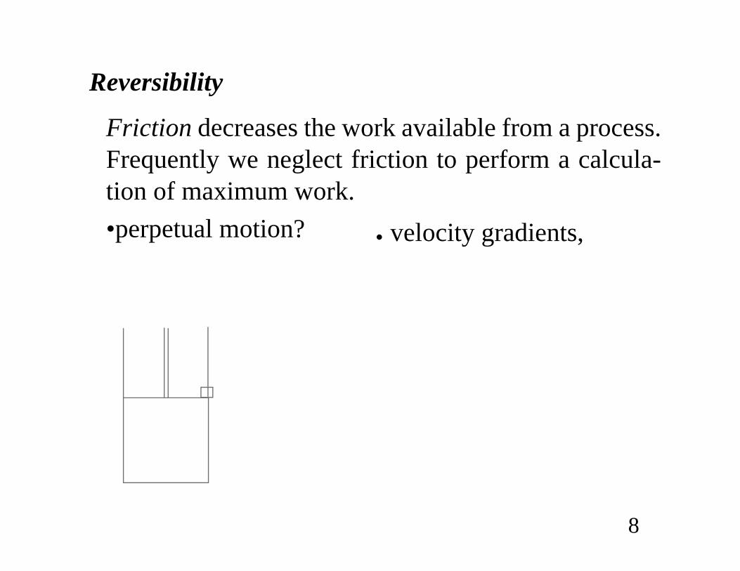
Reversibility
Friction decreases the work available from a process.Frequently we neglect friction to perform a calcula-tion of maximum work.•perpetual motion? velocity gradients,

9
Reversibility by series of equilibrium states
Reversibility by neglecting friction and viscosity

10
Work as a Path Function (Example EL 2.2)Find WEC around path:
V
P1
2
3
V1 V2 = 2 V1

11
14,865 cm3
step A) isothermally expand that gas
= -2060 J (ig)
step B) heat at constant volume back to P1
WEC = 0 (because dV = 0 for step)
V1 = nRT/P = 1.2 moles 8.314 cm3MPa 298 K = moleK 0.2 MPa
z W = - = - EC P dV nRT V V1 2 1ln /b g

12
step C) cool isobarically down to V1
= -0.2 MPa(-14865cm3) = 2973 JBack to original state.All state properties returned to their initial values. What is the total work done on the system?
Wtotal = 2060 + 2973 = 913 J (ig)
Exercise: Textbook path. W = -573.6 J
W P1 VdV3
V1– P1 V1 V3–( )–= =

13
Heat has not been accounted for above.
Heat Flow
Cold Hot
Qblock1 Qblock2–=

14
Chapter 2The energy balance and hand calcs
•EL 2.1-2.4 Work, Reversibility•EL 2.5 Path Properties•EL 2.6 Heat Flow•EL 2.7 Closed System
(FR 7.0-7.3) Energy Balance•EL 2.8 Open, Steady-State
(FR 7.4) Balance•EL 2.10 Enthalpy, Heat Capacities
(FR 8.1-8.3b) Latent Heats(FR 8.4a,c)
•EL 2.11, 2.12 Process Equipment•EL 2.13 (FR 7.6) Strategies

15
THE CLOSED-SYSTEM ENERGY BALANCE
A closed system is one in which no mass flows in orout of the system. There are only two ways a closed system can interact with the surroundings, via heat and work interactions.
•By performing enough experiments, we woulddecide that in fact the sum of heat and workinteractions for a closed system is the energychange of the system!

16
See example 2.3 (transfer of heat between blocks) several important point about boundaries, assumptions.
md U u2
2gc--------- g
gc-----z+ + dQ dWS dWEC+ +=
d U u2
2gc--------- g
gc-----z+ + d Q d WS d WEC+ +=
U KE PE+ +( )Δ Q WS WEC+ +=
Differential
Integral

17
Open Steady-State System Balance
0 U u2
2gc--------- gz
gc-----+ +
inm· in
inlets
U u2
2gc--------- gz
gc-----+ +
outm· out
outlets
–
Q· W· S W· flow+ + +
=

18
Enthalpy
0 U PV u2
2gc--------- gz
gc-----+ + +
inm· in
inlets
U PV u2
2gc--------- gz
gc-----+ + +
outm· out
outlets
–
Q· W· S+ +
=
H U PV+≡
0 H u2
2gc--------- gz
gc-----+ +
inm· in
inlets
H u2
2gc--------- gz
gc-----+ +
outm· out
outlets
–
Q· W· S+ +
=

19
Single stream, KE and PE changes small
Need to relate U, H to T, P, V --- Heat capacities
Constant volume heat capacity:
Constant pressure heat capacity:
0 Hm·Δ– Q· W· S+ +=
0 HΔ– Q WS+ +=
C UTv
V
≡ FHGIKJ
∂∂
C HTp
P
≡ FHGIKJ
∂∂

20
Relations between CP and CV
Ideal gases. (ig)
Nonideal gases - defer relation. (Use tables/charts rather than heat capacities for H, U).
CP CV R+=
UΔ CV T( ) TdT1
T2=
Ideal gas: exact.Real gas: valid only if V = constant.

21
CP
L not equal to CPV,
* in text (EL)
HΔ CP T( ) TdT1
T2= Ideal gas: exact.
Real gas: valid only if P = constant.
HΔ CP T( ) TdT1
T2 V PΔ+=
Liquid below Tr = 0.75 or solid: reason-able approximation.

22
Latent Heat•Enthalpy change associated with phase change at
constant T, P is heat of vaporization.•For melting -- heat of fusion.•see appx FR or EL
Heat liquid propanol (25°C) (1) to 150°C at 1 bar (2).(boils at 98°C at 1 bar)
23
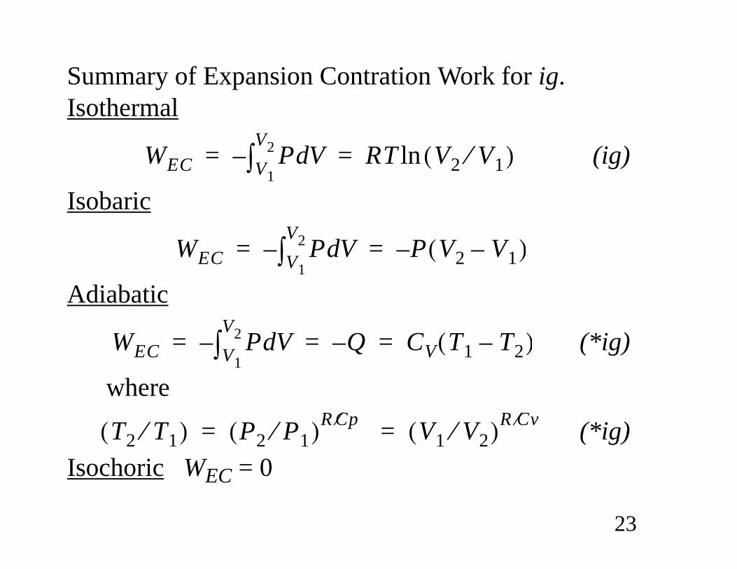
Summary of Expansion Contration Work for ig.Isothermal
(ig)
Isobaric
Adiabatic
(*ig)
where
(*ig) Isochoric WEC = 0
WEC P VdV1
V2– RT V2 V1⁄( )ln= =
WEC P VdV1
V2– P V2 V1–( )–= =
WEC P VdV1
V2– Q– CV T1 T2–( )= = =
T2 T1⁄( ) P2 P1⁄( )R Cp⁄ V1 V2⁄( )R Cv⁄= =

24
Chapter 2Process Equipment
•EL 2.1-2.4 Work, Reversibility•EL 2.5 Path Properties•EL 2.6 Heat Flow•EL 2.7 Closed System
(FR 7.0-7.3) Energy Balance•EL 2.8 Open, Steady-State
(FR 7.4) Balance•EL 2.10 Enthalpy, Heat Capacities
(FR 8.1-8.3b) Latent Heats(FR 8.4a,c)
•EL 2.11, 2.12 Process Equipment•EL 2.13 (FR 7.6) Strategies

25
Throttles (Joule-Thomson expansion)
Nozzles
0 H u2
2gc-------- gz
gc-----+ +
inm· in H u2
2gc-------- gz
gc-----+ +
outm· out–
Q· W· EC W· S
+
+ +
=
0 H u2
2gc-------- gz
gc-----+ +
inm· in H u2
2gc-------- gz
gc-----+ +
outm· out–
Q· W· EC W· S
+
+ +
=

26
Heat Exchanger
Stream A in Stream A out
Stream B in Stream B out
tube
shell
Illustration of a generic heat exchanger with a cocurrent flow pattern.

27
Turbine or Expander
0 H u2
2gc-------- gz
gc-----+ +
inm· in H u2
2gc-------- gz
gc-----+ +
outm· out–
Q· W· EC W· S
+
+ +
=
ShaftInlet
Outlet
rotorsstators

28
Pumps/CompressorsSimilar to turbines/expanders
Pump (liquid) (adiabatic)
0 m· H1 m· H2– W· S+=
m· ΔH W· S= ΔH WS=
1 2

29
Chapter 2Strategies
•EL 2.1-2.4 Work, Reversibility•EL 2.5 Path Properties•EL 2.6 Heat Flow•EL 2.7 Closed System
(FR 7.0-7.3) Energy Balance•EL 2.8 Open, Steady-State
(FR 7.4) Balance•EL 2.10 Enthalpy, Heat Capacities
(FR 8.1-8.3b) Latent Heats(FR 8.4a,c)
•EL 2.11, 2.12 Process Equipment•EL 2.13 (FR 7.6) Strategies

30
Strategies1.Choose boundaries; decide open or closed. 2.steady or unsteady-state?•For open, steady-state systems, solve mass balance
and if possible.3.How many state variables are needed?

31
4.Simplify energy balance. For unsteady-state problems:
Closed system-- integrate the accumulation ofenergy directly without combining with otherenergy balance terms.
5.Look for key words: adiabatic, isolated, throttling, nozzle, reversible,
irreversible.

32
6.Introduce the thermodynamic properties of thefluid (the equation of state). This provides allequations relating P, V, T, U, H, CP, CV. Either 1) the ideal gas approximation; 2) a thermody-namic chart or table; or 3) a volumetric equation ofstate (which will be introduced in Chapter 6). Tryto avoid using more than one model.
Combine with energy balance. 7.Move boundary if necessary. Try overall balance.8.Verify assumptions when done.