chapter 20 - 1 how are electrical conductance and resistance characterized ? what are the physical...
TRANSCRIPT
Chapter 20 - 1
• How are electrical conductance and resistance characterized?
• What are the physical phenomena that distinguish conductors, semiconductors, and insulators?
Electrical Properties

Chapter 20 - 2
Electrical Conduction
• Resistivity, and Conductivity, : -- geometry-independent forms of Ohm's Law
conductivity
-- Resistivity is a material property & is independent of sample
1
• Ohm's Law:V = I R
voltage drop (volts = J/C) C = Coulomb
resistance (Ohms)current (amps = C/s)
Ie-A
(cross sect. area) V
L

Chapter 20 - 3
• Room T values (Ohm-m)-1
Selected values from Tables 18.1, 18.3, and 18.4, Callister 7e.
Conductivity: Comparison
Silver 6.8 x 10 7
Copper 6.0 x 10 7
Iron 1.0 x 10 7
METALS conductors
Silicon 4 x 10⁻⁴
Germanium 2 x 10 0
GaAs 10 -6
SEMICONDUCTORS
semiconductors
= ( - m)-1
Polystyrene <10-14
Polyethylene 10-15-10-17
Soda-lime glass 10
Concrete 10-9
Aluminum oxide <10-13
CERAMICS
POLYMERS
insulators
-10-10-11

Chapter 20 - 4
Energy States: Insulators & Semiconductors
• Insulators: -- Higher energy states not accessible due to gap (> 2 eV).
Energy
filled band
filled valence band
empty band
fille
d st
ates
GAP
• Semiconductors: -- Higher energy states separated by smaller gap (< 2 eV).
Energy
filled band
filled valence band
empty band
fille
d st
ates
GAP?

Chapter 20 - 5
• Intrinsic: # electrons = # holes (n = p) --case for pure Si
• Extrinsic: --n ≠ p --occurs when impurities are added with a different # valence electrons than the host (e.g., Si atoms)
Intrinsic vs Extrinsic Conduction
• n-type Extrinsic: (n >> p)
no applied electric field
5+
4+ 4+ 4+ 4+
4+
4+4+4+4+
4+ 4+
Phosphorus atom
valence electron
Si atom
conduction electron
hole
een
• p-type Extrinsic: (p >> n)
no applied electric field
Boron atom
3+
4+ 4+ 4+ 4+
4+
4+4+4+4+
4+ 4+ hep
Adapted from Figs. 18.12(a) & 18.14(a), Callister 7e.

Chapter 20 - 6
• Allows flow of electrons in one direction only (e.g., useful to convert alternating current to direct current.• Processing: diffuse P into one side of a B-doped crystal.• Results:
--No applied potential: no net current flow.
--Forward bias: carrier flow through p-type and n-type regions; holes and electrons recombine at p-n junction; current flows.
--Reverse bias: carrier flow away from p-n junction; carrier conc. greatly reduced at junction; little current flow.
p-n Rectifying Junction
++
++
+- ---
-p-type n-type
+ -
++ +
++
--
--
-
p-type n-typeAdapted from Fig. 18.21, Callister 7e.
+++
+
+
---
--
p-type n-type- +

Chapter 20 - 7
Properties of Rectifying Junction
Fig. 18.22, Callister 7e. Fig. 18.23, Callister 7e.

Chapter 20 -
Transistor MOSFET• MOSFET (metal oxide semiconductor field effect transistor)
Fig. 18.24, Callister 7e.
Fig. 18.25, Callister 7e.

Chapter 20 - 9
Integrated Circuit Devices
• Integrated circuits - state of the art ca. 50 nm line width– > 100,000,000 components on chip– chip formed layer by layer
• Al is the “wire”
Fig. 18.26, Callister 6e.

Chapter 20 -10
Ferroelectric CeramicsFerroelectric Ceramics are dipolar below Curie TC = 120ºC
• cooled below Tc in strong electric field - make material with strong dipole moment
Fig. 18.35, Callister 7e.
Chapter 20 -11
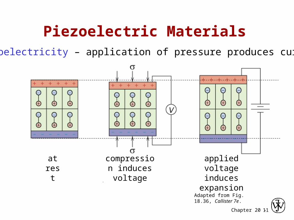
Piezoelectric Materials
at rest
compression induces voltage
applied voltage induces
expansion
Adapted from Fig. 18.36, Callister 7e.
Piezoelectricity – application of pressure produces current

Chapter 20 -12
• Electrical conductivity and resistivity are: -- material parameters. -- geometry independent.• Electrical resistance is: -- a geometry and material dependent parameter.• Conductors, semiconductors, and insulators... -- differ in accessibility of energy states for conductance electrons.• For metals, conductivity is increased by -- reducing deformation -- reducing imperfections -- decreasing temperature.• For pure semiconductors, conductivity is increased by -- increasing temperature -- doping (e.g., adding B to Si (p-type) or P to Si (n-type).
Summary

Chapter 20 -13
ISSUES TO ADDRESS...
• How do we measure magnetic properties?
• What are the atomic reasons for magnetism?
• Materials design for magnetic storage.
• How are magnetic materials classified?
Chapter 20: Magnetic Properties
• What is the importance of superconducting magnets?

Chapter 20 -14
• Created by current through a coil:
• Relation for the applied magnetic field, H:
L
INH
applied magnetic fieldunits = (ampere-turns/m)
current
Applied Magnetic Field
Applied magnetic field H
current I
N = total number of turnsL = length of each turn

Chapter 20 -15
• Magnetic induction results in the material
• Magnetic susceptibility, (dimensionless)
Response to a Magnetic Field
current I
B = Magnetic Induction (tesla) inside the material
measures the material responserelative to a vacuum.
H
B
vacuum = 0
> 0
< 0

Chapter 20 -16
• Measures the response of electrons to a magnetic field.
• Electrons produce magnetic moments:
• Net magnetic moment: --sum of moments from all electrons.
• Three types of response...
Magnetic Susceptibility
Adapted from Fig. 20.4, Callister 7e.
magnetic moments
electron
nucleus
electron
spin

Chapter 20 -17
Plot adapted from Fig. 20.6, Callister 7e. Values and materials from Table 20.2 and discussion in Section 20.4, Callister 7e.
3 Types of Magnetism
Magnetic induction B (tesla)
Strength of applied magnetic field (H) (ampere-turns/m)
vacuum ( = 0) -5diamagnetic ( ~ -10 ) (1)
e.g., Al2O3, Cu, Au, Si, Ag, Zn
ferromagnetic e.g. Fe3O4, NiFe2O4
ferrimagnetic e.g. ferrite(), Co, Ni, Gd
(3)
( as large as 106 !)
(2) paramagnetice.g., Al, Cr, Mo, Na, Ti, Zr
( ~ 10 -4)
permeability of a vacuum:
(1.26 x 10⁻⁶ Henries/m)
HB o )1(

Chapter 20 -18
Magnetic Moments for 3 Types
Adapted from Fig. 20.5(a), Callister 7e.
No Applied Magnetic Field (H = 0)
Applied Magnetic Field (H)
(1) diamagnetic
none
oppo
sing
Adapted from Fig. 20.5(b), Callister 7e.
(2) paramagnetic
rand
om
alig
ned
Adapted from Fig. 20.7, Callister 7e.
(3) ferromagnetic ferrimagnetic
alig
ned
alig
ned

Chapter 20 -19
• As the applied field (H) increases... --the magnetic moment aligns with H.
Adapted from Fig. 20.13, Callister 7e. (Fig. 20.13 adapted from O.H. Wyatt and D. Dew-Hughes, Metals, Ceramics, and Polymers, Cambridge University Press, 1974.)
Ferro- & Ferri-Magnetic Materials
Applied Magnetic Field (H)
Mag
netic
in
duct
ion
(B)
0
Bsat
H = 0
H
H
H
H
H
• “Domains” with aligned magnetic moment grow at expense of poorly aligned ones!

Chapter 20 -20
Adapted from Fig. 20.14, Callister 7e.
Permanent Magnets
Applied Magnetic Field (H)
1. initial (unmagnetized state)
B
large coercivity--good for perm magnets--add particles/voids to make domain walls hard to move (e.g., tungsten steel:
Hc = 5900 amp-turn/m)
• Hard vs Soft Magnets
small coercivity--good for elec. motors(e.g., commercial iron 99.95 Fe)
Adapted from Fig. 20.19, Callister 7e. (Fig. 20.19 from K.M. Ralls, T.H. Courtney, and J. Wulff, Introduction to Materials Science and Engineering, John Wiley and Sons, Inc., 1976.)
Applied Magnetic Field (H)
B
Har
d
So
ft H
ard
• Process: 2. apply H, cause alignment
4
Negative H needed to demagnitize!
. Coercivity, HC
3. remove H, alignment stays! => permanent magnet!

Chapter 20 -21
• Information is stored by magnetizing material.
Image of hard drive courtesy Martin Chen.Reprinted with permissionfrom International Business Machines Corporation.
• Head can... -- apply magnetic field H & align domains (i.e., magnetize the medium). -- detect a change in the magnetization of the medium.
• Two media types:
recording head
recording medium
Adapted from Fig. 20.23, Callister 7e. (Fig. 20.23 from J.U. Lemke, MRS Bulletin, Vol. XV, No. 3, p. 31, 1990.)
Magnetic Storage
-- Particulate: needle-shaped
-Fe2O3. +/- mag. moment along axis. (tape, floppy)
Adapted from Fig. 20.24, Callister 7e. (Fig. 20.24 courtesy P. Rayner and N.L. Head, IBM Corporation.)
~2.5 m
Adapted from Fig. 20.25(a), Callister 7e. (Fig. 20.25(a) from M.R. Kim, S. Guruswamy, and K.E. Johnson, J. Appl. Phys., Vol. 74 (7), p. 4646, 1993. )
~120 nm
--Thin film: CoPtCr or CoCrTa alloy. Domains are ~ 10 - 30 nm! (hard drive)
Chapter 20 -22
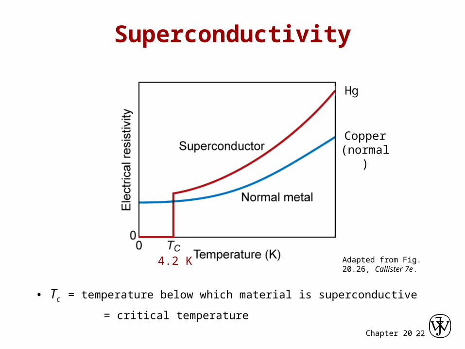
Superconductivity
• Tc = temperature below which material is superconductive
= critical temperature
Copper (normal)
Hg
4.2 K Adapted from Fig. 20.26, Callister 7e.

Chapter 20 -23
Limits of Superconductivity
• 26 metals + 100’s of alloys & compounds • Unfortunately, not this simple:
Jc = critical current density if J > Jc not superconducting
Hc = critical magnetic field if H > Hc not superconducting
Hc= Ho (1- (T/Tc)2)
Adapted from Fig. 20.27, Callister 7e.

Chapter 20 -24
Advances in Superconductivity
• This research area was stagnant for many years.
– Everyone assumed Tc,max was about 23 K
– Many theories said you couldn’t go higher
• 1987- new results published for Tc > 30 K
– ceramics of form Ba1-x Kx BiO3-y
– Started enormous race. • Y Ba2Cu3O7-x Tc = 90 K
• Tl2Ba2Ca2Cu3Ox Tc = 122 K
• tricky to make since oxidation state is quite important
• Values now stabilized at ca. 120 K

Chapter 20 -25
Meissner Effect
• Superconductors expel magnetic fields
• This is why a superconductor will float above a magnet
normal superconductorAdapted from Fig. 20.28, Callister 7e.

Chapter 20 -26
Current Flow in Superconductors
• Type I current only in outer skin- so amount of current
limited
• Type II current flows within wire
M
H
Type I
Type II
complete diamagnetism mixed
state
HC1 HC2HC
normal

Chapter 20 -27
• A magnetic field can be produced by: -- putting a current through a coil.• Magnetic induction: -- occurs when a material is subjected to a magnetic field. -- is a change in magnetic moment from electrons. • Types of material response to a field are: -- ferri- or ferro-magnetic (large magnetic induction) -- paramagnetic (poor magnetic induction) -- diamagnetic (opposing magnetic moment)• Hard magnets: large coercivity.• Soft magnets: small coercivity.• Magnetic storage media: -- particulate -Fe2O3 in polymeric film (tape or floppy) -- thin film CoPtCr or CoCrTa on glass disk (hard drive)
Summary

Chapter 20 -28