chapter 21 alternating current circuits and ... current circuits and electromagnetic waves ... 1.20...
TRANSCRIPT

317
Chapter 21
Alternating Current Circuits and Electromagnetic Waves
Problem Solutions
21.1 (a) ,rms rms 8.00 A 12.0 96.0 VRV I R
(b) ,max ,rms2 2 96.0 V 136 VR RV V
(c) max rms2 2 8.00 A 11.3 AI I
(d) 22
av rms 8.00 A 12.0 768 WI RP
21.2 (a) 2 2
,max ,rms2 2 1.20 10 V 1.70 10 VR RV V
(b)
222 2
2 2rms rmsav rms
av
1.20 10 V 2.40 10
60.0 W
V VI R R
RP
P
(c) Because 2
rms
av
VR
P (see above), if the bulbs are designed to operate at the same
voltage, 2the 1.00 10 W will have the lower resistance.
21.3 The meters measure the rms values of potential d ifference and current. These are
maxrms
100 V70.7 V
2 2
VV , and rms
rms
70.7 V2.95 A
24.0
VI
R
318 CHAPTER 21
21.4 All lamps are connected in parallel with the voltage source, so rms 120 VV for each
lamp. Also, the current is rms av rmsI P V and the resistance is
rms rmsR V I .
1, rms 2, rms
150 W1.25 A
120 VI I and 1 2
120 V96.0
1.25 AR R
3, rms
100 W0.833 A
120 VI and 3
120 V144
0.833 AR
21.5 The total resistance (series connection) is 1 2 8.20 10.4 18.6 eqR R R , so the
current in the circuit is
rmsrms
15.0 V0.806 A
18.6 eq
VI
R
The power to the speaker is then 22
av rms 0.806 A 10.4 6.76 WspeakerI RP
21.6 The general form of the generator voltage is max sinv V t , so by inspection
(a) ,max 170 VRV and (b)
60 rad s30.0 Hz
2 2 radf
(c) ,max
,rms
170 V120 V
2 2
R
R
VV
(d) ,rms
rms
120 V6.00 A
20.0
RVI
R
(e) max rms2 2 6.00 A 8.49 AI I
(f) 2
av rms 6.00 A 20.0 720 WI RP
(g) The argument of the sine function has units of rad s s radianst .
At 0.0050 st , the instantaneous current is
170 V 170 V
sin 60 rad s 0.005 0 s sin 0.94 rad 6.9 A20.0 20.0
vi
R

Alternating Current Circuits and Electromagnetic Waves 319
21.7 1
2CX
fC, so its units are
1 1 Volt VoltOhm
1 Sec Farad 1 Sec Coulomb Volt Coulomb Sec Amp
21.8 rms
max rms rms
2= 2 = = 2 2
C
VI I V f C
X
(a) 6
max = 2 120 V 2 60.0 Hz 2.20 10 C/V =0.141 A 141 mAI
(b) 6
max = 2 240 V 2 50.0 Hz 2.20 10 C/V =0.235 A 235 mAI
21.9 rmsrms rms= =2
C
VI f C V
X, so
2rms
6rms
0.30 A4.0 10 Hz
2 2 4.0 10 F 30 V
If
C V
21.10 (a) 6
1 1221
2 2 60.0 Hz 12.0 10 FCX
fC
(b) ,rms
rms
36.0 V0.163 A
221
C
C
VI
X
(c) max rms2 2 0.163 A 0.231 AI I
(d) No. The current reaches its maximum value one-quarter cycle before the voltage
reaches its maximum value. From the definition of capacitance, the capacitor
reaches its maximum charge when the voltage across it is also a maxim um.
Consequently, the maximum charge and the maximum current do not occur at the
same time.
21.11 rms maxrms max= =2 2
2C
V VI f C f C V
X
so 5
max
0.75 A1.7 10 F 17 F
2 60 Hz 170 V 2
IC
f V

320 CHAPTER 21
21.12 (a) By inspection, ,max 98.0 VCV , so
,max
,rms
98.0 V69.3 V
2 2
C
C
VV
(b) Also by inspection, 80 rad s , so 80 rad s
40.0 Hz2 2 rad
f
(c) maxrms
0.500 A= = 0.354 A
2 2
II
(d) ,max
max
98.0 V196
0.500 A
C
C
VX
I
(e) 1 1
2CX
fC C, so
51 12.03 10 F 20.3 F
80 rad s 196 C
CX
21.13 2LX f L , and from I
Lt
, we have t
LI
. The units of self inductance
are then Volt sec
amp
tL
I. The units of inductive reactance are given by
1 Volt sec Volt
Ohmsec Amp Amp
LX f L
21.14 (a) 32 2 80.0 Hz 25.0 10 H 12.6 LX f L
(b) ,rms
rms
78.0 V6.19 A
12.6
L
L
VI
X
(c) max rms2 2 6.19 A 8.75 AI I
21.15 The required inductive reactance is ,max ,max
max rms2
L L
L
V VX
I I
and the needed inductance is
,max
3
rms
4.00 V0.750 H
2 2 2 2 2 300.0 Hz 2.00 10 A
LLVX
Lf f I
21.16 Given: 21.20 10 V sin 30 and 0.500 HLv t L

Alternating Current Circuits and Electromagnetic Waves 321
(a) By inspection, 30 rad s , so 30 rad s
15.0 Hz2 2
f
(b) Also by inspection, 2
,max 1.20 10 VLV , so that
2
,max
,rms
1.20 10 V84.9 V
2 2
L
L
VV
(c) 2 30 rad s 0.500 H 47.1 LX fL L
(d) ,rms
rms
84.9 V1.80 A
47.1
L
L
VI
X
(e) max rms2 2 1.80 A 2.55 AI I
(f) The phase d ifference between the voltage across an inductor and the current
through the inductor is 90L, so the average power delivered to the inductor is
,av rms ,rms rms ,rmscos cos 90 0L L L LI V I VP
(g) When a sinusoidal voltage with a peak value ,maxLV is applied to an inductor, the
current through the inductor also varies sinusoidally in time, with the same
frequency as the applied voltage, and has a maximum value of max ,maxL LI V X .
However, the current lags behind the voltage in phase by a quarter-cycle or
2 radians . Thus, if the voltage is given by ,max sinL Lv V t , the current as a
function of time is max sin 2i I t . In the case of the given inductor, the current
through it will be 2.55 A sin 30 2i t .
(h) When 1.00 Ai , we have: sin 30 2 1.00 A 2.55 At , or
1 130 2 sin 1.00 A 2.55 A sin 0.392 0.403 radt
and 22 rad 0.403 rad2.09 10 s 20.9 ms
30 rad st
322 CHAPTER 21
21.17 From BL N I (see Section 20.6 in the textbook), the total flux through the coil is
, totalB BN L I where B
is the flux through a single turn on the coil. Thus,
max,total maxmax
rms 22 2 120 V
0.450 T m2 2 60.0 Hz
B
L
VL I L
X
VL
fL
21.18 (a) The applied voltage is max sin 80.0 V sin 150v V t t , so we have that
max 80.0 VV and 2 150 rad sf . The impedance for the circuit is
2 2 22 2 22 1 2 1L CZ R X X R fL fC R L C
or
2
2 3
6
140.0 150 rad s 80.0 10 H 57.5
150 rad s 125 10 FZ
(b) maxmax
80.0 V1.39 A
57.5
VI
Z
21.19 6
1 166.3
2 2 60.0 Hz 40.0 10 FCX
f C
2 2 22 50.0 0 66.3 83.0 L CZ R X X
(a) rmsrms
30.0 V0.361 A
Z 83.0
VI
(b) , rms rms 0.361 A 50.0 18.1 VRV I R
(c) , rms rms 0.361 A 66.3 23.9 VC CV I X
(d) 1 1 0 66.3
tan tan 53.050.0
L CX X
R
so, the voltage lags behind the current by 53°

Alternating Current Circuits and Electromagnetic Waves 323
21.20 (a) 32 2 50.0 Hz 400 10 H 126 LX f L
6
1 1719
2 2 50.0 Hz 4.43 10 FCX
f C
2 2 22 500 126 719 776 L CZ R X X
max max 0.250 A 776 194 VV I Z
(b) 1 1 126 719
tan tan 49.9500
L CX X
R
Thus, the current leads the voltage by 49.9
21.21 (a) 32 2 240 Hz 2.50 H 3.77 10 LX f L
3
6
1 12.65 10
2 2 240 Hz 0.250 10 FCX
f C
22 22 3900 3.77 2.65 10 1.44 kL CZ R X X
(b) maxmax 3
140 V0.097 2 A
1.44 10
VI
Z
(c)
3
1 13.77 2.65 10
tan tan 51.2900
L CX X
R
(d) 0 , so the voltage leads the current
21.22 2 2 60.0 Hz 0.100 H 37.7 LX fL
6
1 1265
2 2 60.0 Hz 10.0 10 FCX
fC
2 2 22 50.0 37.7 265 233 L CZ R X X
(a) ,rms rms 2.75 A 50.0 138 VRV I R (e)
324 CHAPTER 21
(b) ,rms rms 2.75 A 37.7 104 VL LV I X
(c) rms 2.75 A 265 729 VC CV I X
(d) rms rms 2.75 A 233 641 V I Z
21.23 2 2 60.0 Hz 0.400 H 151 LX f L
6
1 1884
2 2 60.0 Hz 3.00 10 FCX
f C
2 2 22 60.0 151 884 735 RLC L CZ R X X
and rmsrms
RLC
VI
Z
(a) 2
0 733 LC L C L CZ X X X X
rms, rms rms
90.0 V733 89.8 V
735 LC LC LC
RLC
VV I Z Z
Z
(b) 2 2 22 0 60.0 884 886 RC CZ R X
rms, rms rms
90.0 V886 108 V
735 RC RC RC
RLC
VV I Z Z
Z
21.24 32 2 60 Hz 2.8 H 1.1 10 LX fL
2 222 3 3 31.2 10 1.1 10 0 1.6 10 L CZ R X X
(a) maxmax 3
170 V0.11 A
1.6 10
VI
Z
(b) 3 2
, max max 0.11 A 1.2 10 1.3 10 VRV I R
3 2
, max max 0.11 A 1.1 10 1.2 10 VL LV I X
Alternating Current Circuits and Electromagnetic Waves 325
(c) When the instantaneous current is a maximum maxi I , the instantaneous voltage
across the resistor is 2
max , max 1.3 10 VR Rv iR I R V . The instantaneous
voltage across an inductor is always 90° or a quarter cycle out of phase with the
instantaneous current. Thus, when maxi I , 0Lv .
Kirchhoff’ s loop rule always applies to the instantaneous voltages around a closed
path. Thus, for this series circuit, source R Lv v v and at this instant when
maxi I
we have 2
source max 0 1.3 10 Vv I R
(d) When the instantaneous current i is zero, the instantaneous voltage across the
resistor is 0Rv iR . Again, the instantaneous voltage across an inductor is a
quarter cycle out of phase with the current. Thus, when 0i , we must have
2
, max 1.2 10 VL Lv V . Then, applying Kirchhoff’ s loop rule to the
instantaneous voltages around the series circuit at the instant when 0i gives
2
source , max0 1.2 10 VR L Lv v v V
21.25 8
12
1 11.33 10
2 2 60.0 Hz 20.0 10 FCX
f C
2 2
2 2 3 8 850.0 10 1.33 10 1.33 10 RC CZ R X
and secondary 5rms
rms 8
5 000 V3.76 10 A
1.33 10 RC
VI
Z
Therefore, 5 3
, rms rms 3.76 10 A 50.0 10 1.88 Vb bV I R
21.26 (a) 6
1 188.4
2 2 60.0 Hz 30.0 10 FCX
f C
(b) 2 2 22 2 20 60.0 88.4 107 C CZ R X R X
(c) 2
maxmax
1.20 10 V1.12 A
107
VI
Z

326 CHAPTER 21
(d) The phase angle in this RC circuit is
1 1 0 88.4
tan tan 55.860.0
L CX X
R
Since 0 , the voltage lags behind the current by 55.8° . Adding an inductor will
change the impedance and hence the current in the circuit.
21.27 (a) 2 2 50.0 Hz 0.250 H 78.5 LX f L
(b) 3
6
1 11.59 10 1.59 k
2 2 50.0 Hz 2.00 10 FCX
f C
(c) 2 2 22 3150 78.5 1590 1.52 10 1.52 kL CZ R X X
(d) 2
maxmax 3
2.10 10 V0.138 A 138 mA
1.52 10
VI
Z
(e) 1 1 78.5 1590
tan tan 84.3150
L CX X
R
(f) ,max max 0.138 A 150 20.7 VRV I R
,max max 0.138 A 78.5 10.8 VL LV I X
3
,max max 0.138 A 1.59 10 219 VC CV I X
21.28 The voltage across the resistor is a maximum when the current is a maximum, and the
maximum value of the current occurs when the argument of the sine function is 2 .
The voltage across the capacitor lags the current by 90° or 2 rad ians, which
corresponds to an argument of 0 in the sine function and a voltage of 0Cv . Similarly,
the voltage across the inductor leads the current by 90° or 2 rad ians, corresponding
to an argument in the sine function of rad ians or 180°, giving a voltage of 0Lv .
Alternating Current Circuits and Electromagnetic Waves 327
21.29 2 2 50.0 Hz 0.185 H 58.1 LX f L
6
1 149.0
2 2 50.0 Hz 65.0 10 FCX
f C
2 2 22 40.0 58.1 49.0 41.0 ad L CZ R X X
and max
rmsrms
2 150 V2.59 A
41.0 2ad ad
VVI
Z Z
(a) 40.0 abZ R , so rms rms 2.59 A 40.0 104 VababV I Z
(b) 58.1 bc LZ X , and rms rms 2.59 A 58.1 150 VbcbcV I Z
(c) 49.0 cd CZ X , and rms rms 2.59 A 49.0 127 VcdcdV I Z
(d) 9.10 bd L CZ X X , so rms rms 2.59 A 9.10 23.6 VbdbdV I Z
21.30 3
6
1 11.1 10
2 2 60 Hz 2.5 10 FCX
fC
2 222 3 3 31.2 10 0 1.1 10 1.6 10 L CZ R X X
(a) maxmax 3
170 V0.11 A
1.6 10
VI
Z
(b) 3 2
, max max 0.11 A 1.2 10 1.3 10 VRV I R
3 2
, max max 0.11 A 1.1 10 1.2 10 VC CV I X
328 CHAPTER 21
(c) When the instantaneous current i is zero, the instantaneous voltage across the
resistor is 0Rv iR . The instantaneous voltage across a capacitor is always 90°
or a quarter cycle out of phase with the instantaneous current. Thus, when 0i ,
2
, max 1.2 10 VC Cv V
and 6 2 -42.5 10 F 1.2 10 V 3.0 10 C 300 C C Cq C v
Kirchhoff’ s loop rule always applies to the instantaneous voltages around a closed
path. Thus, for this series circuit, source 0R Cv v v , and at this instant when
0i , we have 2
source , max0 1.2 10 VC Cv v V
(d) When the instantaneous current is a maximum max( )i I , the instantaneous voltage
across the resistor is 2
max , max 1.3 10 VR Rv iR I R V . Again, the
instantaneous voltage across a capacitor is a quarter cycle out of phase with the
current. Thus, when maxi I , we must have 0Cv and 0C Cq C v . Then,
applying Kirchhoff’ s loop rule to the instantaneous voltages around the series
circuit at the instant when maxi I and 0Cv gives
2
source source , max0 1.3 10 VR C R Rv v v v v V
21.31 (a) rms
rms
104 V208
0.500 A
VZ
I
(b) 2
av rmsI RP gives av
2 2
rms
10.0 W40.0
0.500 AR
I
P
(c) 2 2
LZ R X , so 2 22 2 208 40.0 204 LX Z R
and 204
0.541 H2 2 60.0 Hz
LXL
f
21.32 Given max sin 90.0 V sin 350v V t t , observe that max 90.0 VV and
350 rad s . Also, the net reactance is 2 1 2 1L CX X fL fC L C .
Alternating Current Circuits and Electromagnetic Waves 329
(a) 6
1 1350 rad s 0.200 H 44.3
350 rad s 25.0 10 FL CX X L
C
so the impedance is 2 2 22 50.0 44.3 66.8 L CZ R X X
(b) rms maxrms
2 90.0 V0.953 A
Z 2 66.8
V VI
Z
(c) The phase d ifference between the applied voltage and the current is
1 1 44.3
tan tan 41.550.0
L CX X
R
so the average power delivered to the circuit is
av
maxrms rms rms
90.0 Vcos cos 0.953 A cos 41.5 45.4 W
2 2
VI V IP
21.33 Please see the textbook for the statement of Problem 21.21 and the answers for that
problem. There, you should find that max max140 V, 0.097 2 A, and 51.2V I . The
average power delivered to the circuit is then
max maxav rms rms
0.097 2 A 140 Vcos cos cos 51.2 4.26 W
22 2
I VI VP
21.34 The rms current in the circuit is
rmsrms
160 V2.00 A
Z 80.0
VI
and the average power delivered to the circuit is
22
av rms rms rms ,rms rms rms rmscos 2.00 A 22.0 88.0 WRI V I V I I R I RP
21.35 (a) 2
av rms rms rms rms , rmsRI R I I R I VP , so avrms
, rms
14 W0.28 A
50 VR
IV
P
Thus, , rms 2
rms
50 V1.8 10
0.28 A
RVR
I
330 CHAPTER 21
(b) 2 2
LZ R X , which yields
2 22
2 2 2 2 2rms
rms
90 V1.8 10 2.7 10
0.28 AL
VX Z R R
I
and 22.7 10
0.72 H2 2 60 Hz
LXL
f
21.36 32 2 600 Hz 6.0 10 H 23 LX fL
-6
1 111
2 2 600 Hz 25 10 FCX
fC
2 2 22 25 23 11 28 L CZ R X X
(a) rms, rms rms
10 V25 8.9 V
28 R
VV I R R
Z
rms, rms rms
10 V23 8.2 V
28 L L L
VV I X X
Z
rms, rms rms
10 V11 3.9 V
28 C C C
VV I X X
Z
, rms , rms , rms No , 9.0 V 8.2 V 3.8 V 21 V 10 VR L CV V V
(b) The power delivered to the resistor is the greatest. No power losses occur in an ideal
capacitor or inductor.
(c)
2 2
2 rmsav rms
10 V25 3.2 W
28
VI R R
ZP
21.37 (a) The frequency of the station should match the resonance frequency of the tuning
circuit. At resonance, L CX X or
0 02 1 2f L f C , which gives 2 2
0 1 4f LC or
7
06 12
1 15.81 10 Hz 58.1 MHz
2 2 3.00 10 H 2.50 10 Ff
LC
Alternating Current Circuits and Electromagnetic Waves 331
(b) Yes, the resistance is not needed. The resonance frequency is found by simply
equating the inductive reactance to the capacitive reactance, which leads to
Equation 21.19 as shown above.
21.38 (a) The resonance frequency of a RLC circuit is 0 1 2f LC . Thus, the inductance is
10
2 2 22 9 12
0
1 11.56 10 H 156 pH
4 4 9.00 10 Hz 2.00 10 FL
f C
(b) 9 10
02 2 9.00 10 Hz 1.56 10 H 8.82 LX f L
21.39 0
1
2f
LC, so
2 2
0
1
4C
f L
For 5
0 0 min500 kHz 5.00 10 Hzf f
8
max 22 5 6
15.1 10 F 51 nF
4 5.00 10 Hz 2.0 10 HC C
For 6
0 0 max1600 kHz 1.60 10 Hzf f
9
min 22 6 6
14.9 10 F 4.9 nF
4 1.60 10 Hz 2.0 10 HC C
21.40 (a) At resonance, L CX X so the impedance will be
22 2 0 15 L CZ R X X R R
(b) When L CX X , we have
12
2fL
fC which yields
6
1 141 Hz
2 2 0.20 H 75 10 Ff
LC
(c) The current is a maximum at resonance where the impedance has its minimum
value of Z R .

332 CHAPTER 21
(d) At 60 Hzf , 2 60 Hz 0.20 H 75 LX , 6
135
2 60 Hz 75 10 FCX ,
and 2 2
15 75 35 43 Z
Thus, max
rmsrms
2 150 V2.5 A
2 43
VVI
Z Z
21.41 0 0
3 6
1 12 1000 rad s
10.0 10 H 100 10 Ff
LC
Thus, 02 2 000 rad s
32 000 rad s 10.0 10 H 20.0 LX L
6
1 15.00
2 000 rad s 100 10 FCX
C
2 2 22 10.0 20.0 5.00 18.0 L CZ R X X
rmsrms
50.0 V2.78 A
18.0
VI
Z
The average power is 22
av rms 2.78 A 10.0 77.3 WI RP
and the energy converted in one period is
av av
2 J 277.3 0.243 J
s 2 000 rad sE TP P
21.42 The resonance frequency is 0 0
12 f
LC
Also, LX L and
1CX
C

Alternating Current Circuits and Electromagnetic Waves 333
(a) At resonance, 0 -6
1 3.00 H1000
3.00 10 FC L
LX X L L
CLC
Thus, 2 20Z R R , rmsrms
120 V4.00 A
30.0
VI
Z
and 22
av rms 4.00 A 30.0 480 WI RP
(b) At 0
1
2;
0
1500
2L LX X ,
0
2 2 000 C CX X
2 2 22 30.0 500 2 000 1500 L CZ R X X
and rms
120 V0.080 0 A
1500 I
so 22
av rms 0.080 0 A 30.0 0.192 WI RP
(c) At 0
1
4;
0
1250
4L LX X ,
0
4 4 000 C CX X
3750 Z , and rms
120 V0.032 0 A
3 750 I
so 22 2
av rms 0.032 0 A 30.0 3.07 10 W 30.7 mWI RP
(d) At 02 ;
0
2 2 000 L LX X , 0
1500
2C CX X
1500 Z , and rms
120 V0.080 0 A
1500 I
so 22
av rms 0.080 0 A 30.0 0.192 WI RP

334 CHAPTER 21
(e) At 04 ;
0
4 4 000 L LX X , 0
1250
4C CX X
3750 Z , and rms
120 V0.032 0 A
3 750 I
so 22 2
av rms 0.032 0 A 30.0 3.07 10 W 30.7 mWI RP
The power delivered to the circuit is a maximum w hen the rms current is a
maximum. This occurs when the frequency of the source is equal to the resonance
frequency of the circuit.
21.43 The maximum output voltage max 2V is related to the maximum input voltage
max 1V by the expression 2
max max2 11
NV V
N, where
1N and 2N are the number of
turns on the primary coil and the secondary coil respectively. Thus, for the given
transformer,
3
max 2
1500170 V 1.02 10 V
250V
and the rms voltage across the secondary is 3
max 2rms 2
1.02 10 V721 V
2 2
VV .
21.44 (a) The output voltage of the transformer is
22,rms 1,rms
1
1120 V 9.23 V
13
NV V
N
(b) Assuming an ideal transformer, output inputP P , and the power delivered to the CD
player is
av av 1,rms 1,rms2 10.250 A 120 V 30.0 WI VP P

Alternating Current Circuits and Electromagnetic Waves 335
21.45 The power input to the transformer is
5
av 1, rms 1, rmsinput3 600 V 50 A 1.8 10 WV IP
For an ideal transformer, av 2, rms 2, rms avouput input
V IP P so the current in the long-
distance power line is
5
av input
2, rms
2, rms
1.8 10 W1.8 A
100 000 VI
V
P
The power d issipated as heat in the line is then
22 2
lost 2, rms line 1.8 A 100 3.2 10 WI RP
The percentage of the power delivered by the generator that is lost in the line is
2
lost
5
input
3.2 10 W% Lost 100% 100% 0.18%
1.8 10 W
P
P
21.46 (a) Since the transformer is to step the voltage down from 120 volts to 6.0 volts, the
secondary must have fewer turns than the primary.
(b) For an ideal transformer, av avinput ouputP P or 1, rms 1, rms 2, rms 2, rmsV I V I so the
current in the primary will be
2, rms 2, rms
1, rms
1, rms
6.0 V 500 mA25 mA
120 V
V II
V
(c) The ratio of the secondary to primary voltages is the same as the ratio of the number
of turns on the secondary and primary coils, 2 1 2 1V V N N . Thus, the number of
turns needed on the secondary coil of this step down transformer is
22 1
1
6.0 V400 20 turns
120 V
VN N
V

336 CHAPTER 21
21.47 (a) At 90% efficiency, av avoutput input
0.90P P
Thus, if av output1000 kWP
the input power to the primary is av output 3
av input
1000 kW1.1 10 kW
0.90 0.90
PP
(b) 3 6
av input 2
1, rms
1, rms 1, rms
1.1 10 kW 1.1 10 W3.1 10 A
3 600 VI
V V
P
(c) 6
av output 3
2, rms
2, rms 1, rms
1000 kW 1.0 10 W8.3 10 A
120 VI
V V
P
21.48 4 54.50 10 m 6.44 10 m 290 lineR
(a) The power transmitted is av rms rmstransmittedV IP
so 6
av transmittedrms 3
rms
5.00 10 W10.0 A
500 10 VI
V
P
Thus, 22 4
av rms lineloss10.0 A 290 2.90 10 W 29.0 kWI RP
(b) The power input to the line is
6 4 6
av av avinput transmitted loss5.00 10 W 2.90 10 W 5.03 10 WP P P
and the fraction of input power lost during transmission is
4
av loss
6
av input
2.90 10 W0.005 77 or 0.577%
5.03 10 Wfraction
P
P
Alternating Current Circuits and Electromagnetic Waves 337
(c) It is impossible to deliver the needed power with an input voltage of 4.50 kV. The
maximum line current with an input voltage of 4.50 kV occurs when the line is
shorted out at the customer’ s end, and th is current is
rmsrms max
line
4 500 V15.5 A
290
VI
R
The maximum input power is then
input rms rms maxmax
3 44.50 10 V 15.5 A 6.98 10 W 6.98 kW
V IP
This is far short of meeting the customer’ s request, and all of this power is lost in
the transmission line.
21.49 From v f , the wavelength is
8
63.00 10 m s4.00 10 m 4 000 km
75 Hz
v
f
The required length of the antenna is then,
4 1000 kmL , or about 621 miles. Not very practical at all.
21.50 (a) 18
2
8 7
6.44 10 m 1 y6.80 10 y
3.00 10 m s 3.156 10 s
dt
c
(b) From Table C.4 (in Appendix C of the textbook), the average Earth-Sun d istance is 111.496 10 md , giving the transit time as
11
8
1.496 10 m 1 min8.31 min
60 s3.00 10 m s
dt
c
(c) Also from Table C.4, the average Earth-Moon d istance is 83.84 10 md , giving the
time for the round trip as
8
8
2 3.84 10 m22.56 s
3.00 10 m s
dt
c

338 CHAPTER 21
21.51 The amplitudes of the electric and magnetic components of an electromagnetic wave are
related by the expression max maxE B c , thus the amplitude of the magnetic field is
6maxmax 8
330 V m1.10 10 T
3.00 10 m s
EB
c
21.52 7 2 2 12 2 2
0 0
1 1
4 10 N s C 8.854 10 C N mc
or 82.998 10 m sc
21.53 (a) The frequency of an electromagnetic wave is f c , where c is the speed of light,
and is the wavelength of the wave. The frequencies of the two light sources are
then
Red: 8
14
red -9
red
3.00 10 m s4.55 10 Hz
660 10 m
cf
and
Infrared: 8
14
IR -9
IR
3.00 10 m s3.19 10 Hz
940 10 m
cf
(b) The intensity of an electromagnetic wave is proportional to the square of its
amplitude. If 67% of the incident intensity of the red light is absorbed, then the
intensity of the emerging wave is 100% 67% 33% of the incident intensity, or
0.33f iI I . Hence, we must have
max,
max,
0.33 0.57f f
i i
E I
E I

Alternating Current Circuits and Electromagnetic Waves 339
21.54 If 0I is the incident intensity of a light beam, and I is the intensity of the beam after
passing through length L of a fluid having concentration C of absorbing molecules, the
Beer-Lambert law states that 10 0log I I CL where is a constant.
For 660-nm light, the absorbing molecules are oxygenated hemoglobin. Thus, if 33% of
this wavelength light is transmitted through blood, the concentration of oxygenated
hemoglobin in the blood is
10
HBO2
log 0.33C
L [1]
The absorbing molecules for 940-nm light are deoxygenated hemoglobin, so if 76% of
this light is transmitted through the blood, the concentration of these molecules in the
blood is
10
HB
log 0.76C
L [2]
Divid ing equation [2] by equation [1] gives the ratio of deoxygenated hemoglobin to
oxygenated hemoglobin in the blood as
10HB
HB HBO2
HBO2 10
log 0.760.25 or 0.25
log 0.33
CC C
C
Since all the hemoglobin in the blood is either oxygenated or deoxygenated , it is
necessary that HB HBO2 1.00C C , and we now have
HBO2 HBO2 0.25 1.0C C . The fraction
of hemoglobin that is oxygenated in this blood is then
HBO2
1.00.80 or 80%
1.0 0.25C
Someone with only 80% oxygenated hemoglobin in the blood is probably in serious
trouble needing supplemental oxygen immediately.
21.55 From max max
02
E BIntensity and max
max
Ec
B, we find
2
max
02
c BIntensity
Thus,
7
2 60max 8
2 4 10 T m A21340 W m 3.35 10 T
3.00 10 m sB Intensity
c
and 6 8 3
max max 3.35 10 T 3.00 10 m s 1.01 10 V mE B c
340 CHAPTER 21
21.56 (a) To exert an upward force on the d isk, the laser beam should be aimed vertically
upward , striking the lower surface of the d isk. To just levitate the d isk, the upward
force exerted on the d isk by the beam should equal the weight of the d isk.
The momentum that electromagnetic radiation of intensity I, incident normally on
a perfectly reflecting surface of area A , delivers to that surface in time t is given by
Equation 21.30 as 2 2p U c IA t c . Thus, from the impulse-momentum
theorem, the average force exerted on the reflecting surface is 2F p t IA c .
Then, to just levitate the surface, 2F IA c mg and the required intensity of the
incident rad iation is 2I mgc A .
(b)
3 2 8
9 2
2 2-2
5.00 10 kg 9.80 m s 3.00 10 m s1.46 10 W m
2 2 2 4.00 10 m
mgc mgcI
A r
(c) Propulsion by light pressure in a significant gravity field is impractica l because of
the enormous power requirements. In addition, no material is perfectly reflecting,
so the absorbed energy would melt the reflecting surface.
21.57 The d istance between adjacent antinodes in a standing wave is 2
Thus, 2 6.00 cm 12.0 cm 0.120 m , and
9 80.120 m 2.45 10 Hz 2.94 10 m sc f
21.58 At Earth’ s location, the wave fronts of the solar rad iation are spheres whose radius is the
Sun-Earth d istance. Thus, from av av
24Intensity
A r
P P, the total power is
2
2 11 26
av 2
W4 1340 4 1.49 10 m 3.74 10 W
mIntensity rP
21.59 From f c , we find 8
14
7
3.00 10 m s5.45 10 Hz
5.50 10 m
cf
21.60 8
6
3.00 10 m s11.0 m
27.33 10 Hz
c
f

Alternating Current Circuits and Electromagnetic Waves 341
21.61 (a) For the AM band,
8
min 3
max
3.00 10 m s188 m
1600 10 Hz
c
f
8
max 3
min
3.00 10 m s556 m
540 10 Hz
c
f
(b) For the FM band,
8
min 6
max
3.00 10 m s2.78 m
108 10 Hz
c
f
8
max 6
min
3.00 10 m s3.4 m
88 10 Hz
c
f
21.62 The transit time for the radio wave is
3
4
8
100 10 m3.33 10 s 0.333 ms
3.00 10 m s
RR
dt
c
and that for the sound wave is
3
sound
3.0 m8.7 10 s 8.7 ms
343 m s
ss
dt
v
Thus, the radio listeners hear the news 8.4 ms before the studio audience because radio
waves travel so much faster than sound waves.

342 CHAPTER 21
21.63 If an object of mass m is attached to a spring of spring constant k, the natural frequency
of vibration of that system is 2f k m . Thus, the resonance frequency of the C=O
double bond will be
13
26
oxygenatom
1 1 2 800 N m5.2 10 Hz
2 2 2.66 10 kg
kf
m
and the light with this frequency has wavelength
8
6
13
3.00 10 m s5.8 10 m 5.8 m
5.2 10 Hz
c
f
The infrared region of the electromagnetic spectrum ranges from max 1 mm down to
min 700 nm 0.7 m . Thus, the required wavelength falls within the infrared region .
21.64 Since the space station and the ship are moving toward one another, the frequency after
being Doppler shifted is 1O Sf f u c , so the change in frequency is
5
14 11
8
1.8 10 m s6.0 10 Hz 3.6 10 Hz
3.0 10 m sO S S
uf f f f
c
and the frequency observed on the spaceship is
14 11 146.0 10 Hz 3.6 10 Hz 6.003 6 10 HzO Sf f f
21.65 Since you and the car ahead of you are moving away from each other (getting farther
apart) at a rate of 120 km h 80 km h 40 km hu , the Doppler shifted frequency you
will detect is 1O Sf f u c , and the change in frequency is
14 7
8
40 km h 0.278 m s4.3 10 Hz 1.6 10 Hz
1 km h3.0 10 m sO S S
uf f f f
c
The frequency you will detect will be
14 7 144.3 10 Hz 1.6 10 Hz 4.299 999 84 10 HzO Sf f f
Alternating Current Circuits and Electromagnetic Waves 343
21.66 The driver was driving toward the warning lights, so the correct form of the Doppler
shift equation is 1O Sf f u c . The frequency emitted by the yellow warning light is
8
14
9
3.00 10 m s5.17 10 Hz
580 10 mS
S
cf
and the frequency the driver claims that she observed is
8
14
9
3.00 10 m s5.36 10 Hz
560 10 mO
O
cf
The speed with which she would have to approach the light for the Doppler effect to
yield this claimed shift is
14
8 7
14
5.36 10 Hz1 3.00 10 m s 1 1.1 10 m s
5.17 10 Hz
O
S
fu c
f
21.67 (a) At 60.0 Hzf , the reactance of a 15.0- F capacitor is
6
1 1177
2 2 60.0 Hz 15.0 10 FCX
fC
and the impedance of this RC circuit is
2 22 2 50.0 177 184 CZ R X
(b) 2
rmsrms
1.20 10 V0.652 A 652 mA
Z 184
VI
344 CHAPTER 21
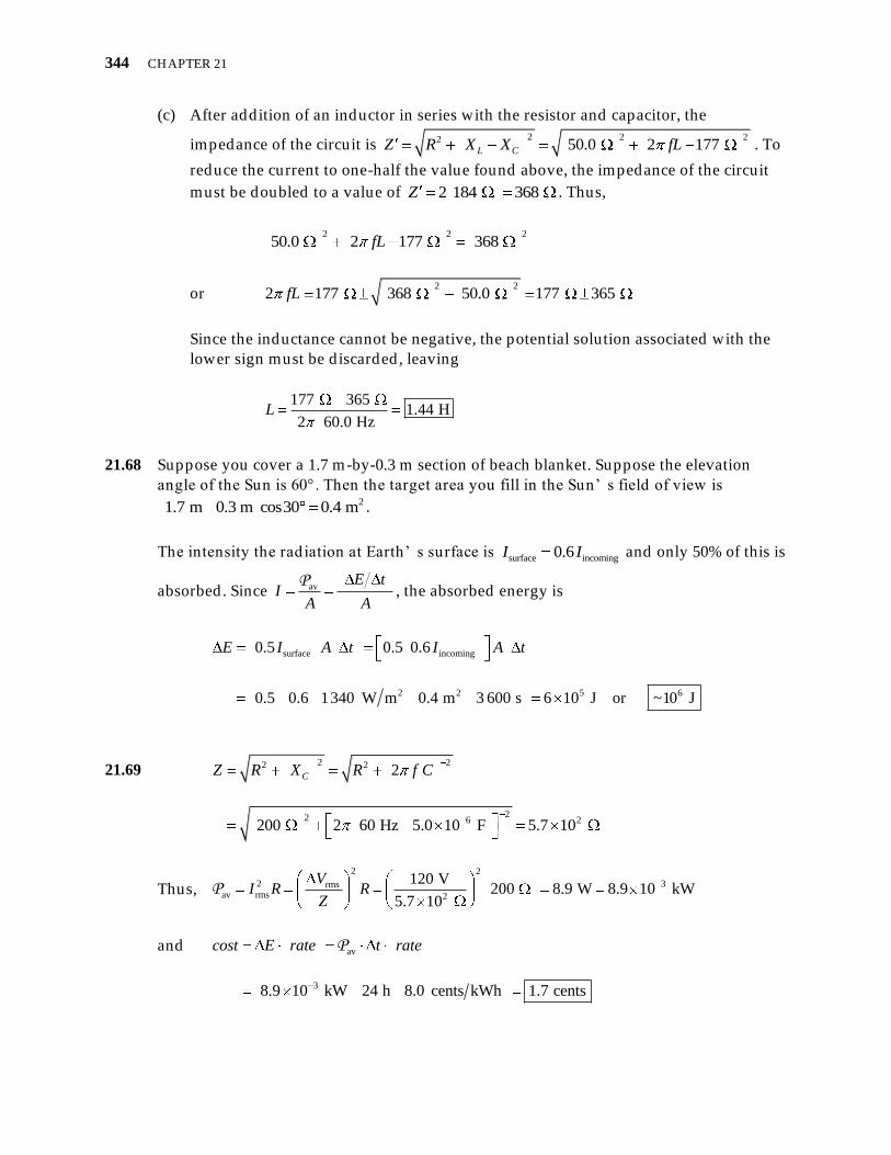
(c) After addition of an inductor in series with the resistor and capacitor, the
impedance of the circuit is 2 2 22 50.0 2 177 L CZ R X X fL . To
reduce the current to one-half the value found above, the impedance of the circuit
must be doubled to a value of 2 184 368 Z . Thus,
2 2 2
50.0 2 177 368 fL
or 2 2
2 177 368 50.0 177 365 fL
Since the inductance cannot be negative, the potential solution associated with the
lower sign must be d iscarded, leaving
177 365
1.44 H2 60.0 Hz
L
21.68 Suppose you cover a 1.7 m-by-0.3 m section of beach blanket. Suppose the elevation
angle of the Sun is 60°. Then the target area you fill in the Sun’ s field of view is 21.7 m 0.3 m cos30 0.4 m .
The intensity the radiation at Earth’ s surface is surface incoming0.6I I and only 50% of this is
absorbed. Since avE t
IA A
P, the absorbed energy is
surface incoming
2 2 5 6
0.5 0.5 0.6
0.5 0.6 1340 W m 0.4 m 3 600 s 6 10 J or ~10 J
E I A t I A t
21.69 2 22 2
22 6 2
2
200 2 60 Hz 5.0 10 F 5.7 10
CZ R X R f C
Thus,
2 2
2 3rmsav rms 2
120 V200 8.9 W 8.9 10 kW
5.7 10
VI R R
ZP
and av
38.9 10 kW 24 h 8.0 cents kWh 1.7 cents
cost E rate t rateP

Alternating Current Circuits and Electromagnetic Waves 345
21.70 LX L , so
LX L
Then, 1 1
C
L
XC C X L
which gives
12 8.0 L CL X X C C or 296 L C [1]
From 0 0
12 f
LC, we obtain
2
0
1
2LC
f
Substituting from Equation [1], this becomes 2 2
2
0
196
2C
f
or 5
2 2
0
1 12.6 10 F 26 F
2 96 2 2 000 Hz 96 C
f
Then, from Equation [1],
2 5 396 2.6 10 F 2.5 10 H 2.5 mHL
21.71 DC
DC
12.0 V19.0
0.630 A
VR
I
22 rms
rms
24.0 V2 42.1
0.570 A
VZ R f L
I
Thus,
2 22 2
242.1 19.0
9.97 10 H 99.7 mH2 2 60.0 Hz
Z RL
f
21.72 (a) The required frequency is 8
10
2
3.00 10 m s1.0 10 Hz
3.00 10 m
cf . Therefore, the
resonance frequency of the circuit is 10
0
11.0 10 Hz
2f
LC, giving
13
2 210 12
0
1 16.3 10 F 0.63 pF
2 2 10 Hz 400 10 HC
f L

346 CHAPTER 21
(b) 2
0 0AC
d d, so
13 3
3
12 2
0
6.3 10 F 1.0 10 m8.4 10 m 8.4 mm
8.85 10 C N m
C d
(c) 10 12
02 2 1.0 10 Hz 400 10 H 25 C LX X f L
21.73 (a) max
max
Ec
B, so
6
16maxmax 8
0.20 10 V m6.7 10 T
3.00 10 m s
EB
c
(b)
6 16
17 2max max
70
0.20 10 V m 6.7 10 T5.3 10 W m
2 2 4 10 T m A
E BIntensity
(c) 2
av
2
17 2 14
4
20.0 m5.3 10 W m 1.7 10 W
4
dIntensity A IntensityP
21.74 (a) rms
rms
12 V6.0
2.0 A
VZ
I
(b) DC
DC
12 V4.0
3.0 A
VR
I
From 22 2 2 2LZ R X R f L , we find
2 22 2
26.0 4.0
1.2 10 H 12 mH2 2 60 Hz
Z RL
f

Alternating Current Circuits and Electromagnetic Waves 347
21.75 (a) From Equation 21.30, the momentum imparted in time t to a perfectly reflecting
sail of area A by normally incident rad iation of intensity I is 2 2p U c IA t c .
From the impulse-momentum theorem, the average force exerted on the sail is then
2 4 2
av 8
2 1340 W m 6.00 10 m2 20.536 N
3.00 10 m s
IA t cp IAF
t t c
(b) 5 2avav
0.536 N8.93 10 m s
6 000 kg
Fa
m
(c) From 2
0
1
2x v t at , with
0 0v , the time is
8
6
5 2 4
av
2 3.84 10 m2 1 d2.93 10 s 33.9 d
8.93 10 m s 8.64 10 s
xt
a
21.76 (a) The intensity of rad iation at d istance r from a point source, which radiates total
power P , is 24I A rP P . Thus, at d istance 2.0 inr from a cell phone
radiating a total power of 32.0 W 2.0 10 mWP , the intensity is
3
2
2
2.0 10 mW6.2 mW cm
4 2.0 in 2.54 cm 1 inI
This intensity is 24% higher than the maximum allowed leakage from a microwave at this
d istance of 2.0 inches.
(b) If when using a Blue tooth headset (emitting 2.5 mW of power) in the ear at d istance
2.0 in 5.1 cmhr from center of the brain, the cell phone (emitting 2.0 W of power)
is located in the pocket at d istance 21.0 m 1.0 10 cmpr from the brain, the total
rad iation intensity at the brain is
3
2 3
total phone headset 2 2 2 22
2.0 10 mW 2.5 mW mW mW1.6 10 7.6 10
cm cm4 5.1 cm4 1.0 10 cmI I I
or 2 3 2 2
total 2 2 2
mW mW mW1.6 10 7.6 10 2.4 10 0.024 mW cm
cm cm cmI