chapter 23
DESCRIPTION
Chapter 23. Faraday’s Law and Induction. 23.1 Michael Faraday. 1791 – 1867 British experimental physicist Contributions to early electricity include Invention of motor, generator, and transformer Electromagnetic induction Laws of electrolysis. Induction. - PowerPoint PPT PresentationTRANSCRIPT
Chapter 23
Faraday’s Law
and
Induction
2
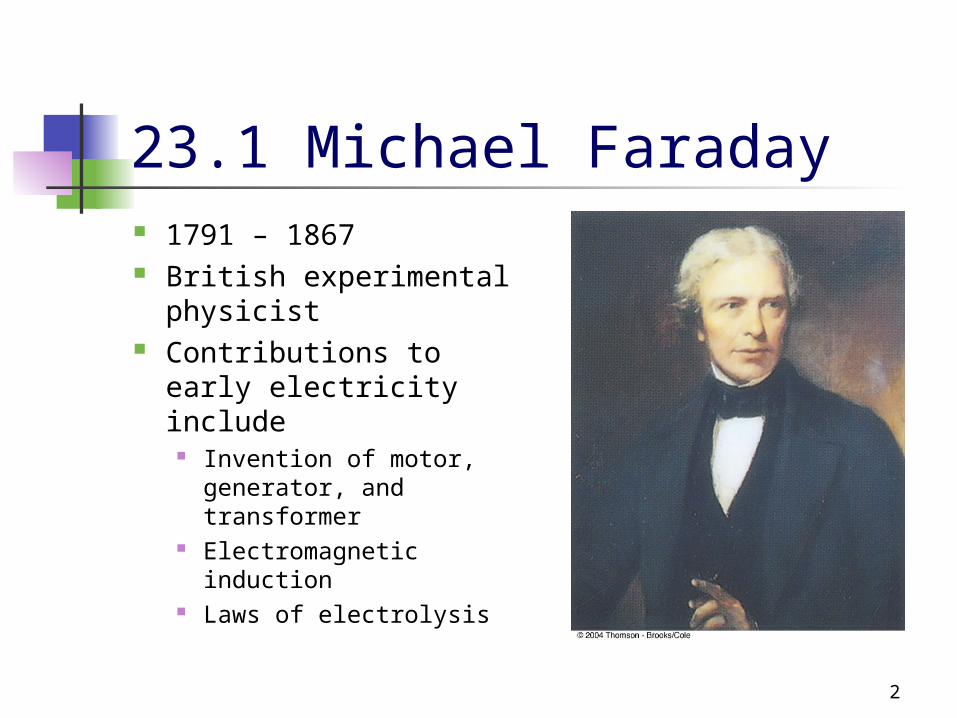
23.1 Michael Faraday 1791 – 1867 British experimental
physicist Contributions to early
electricity include Invention of motor,
generator, and transformer
Electromagnetic induction
Laws of electrolysis

3
Induction A changing magnetic field produces an
induced current on a circuit without the present of a battery in the circuit
There is an induced emf associated with the induced current
Faraday’s Law of Induction describes the induced emf
4
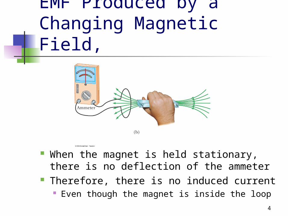
EMF Produced by a Changing Magnetic Field,
When the magnet is held stationary, there is no deflection of the ammeter
Therefore, there is no induced current Even though the magnet is inside the loop
5
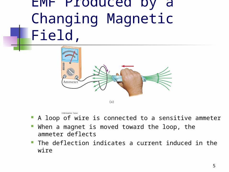
EMF Produced by a Changing Magnetic Field,
A loop of wire is connected to a sensitive ammeter When a magnet is moved toward the loop, the
ammeter deflects The deflection indicates a current induced in the wire

6
EMF Produced by a Changing Magnetic Field,
The magnet is moved away from the loop The ammeter deflects in the opposite
direction
7
EMF Produced by a Changing Magnetic Field, Summary The ammeter deflects when the magnet is
moving toward or away from the loop The ammeter also deflects when the loop is
moved toward or away from the magnet An electric current is set up in the coil as long
as relative motion occurs between the magnet and the coil This is the induced current that is produced by an
induced emf
8
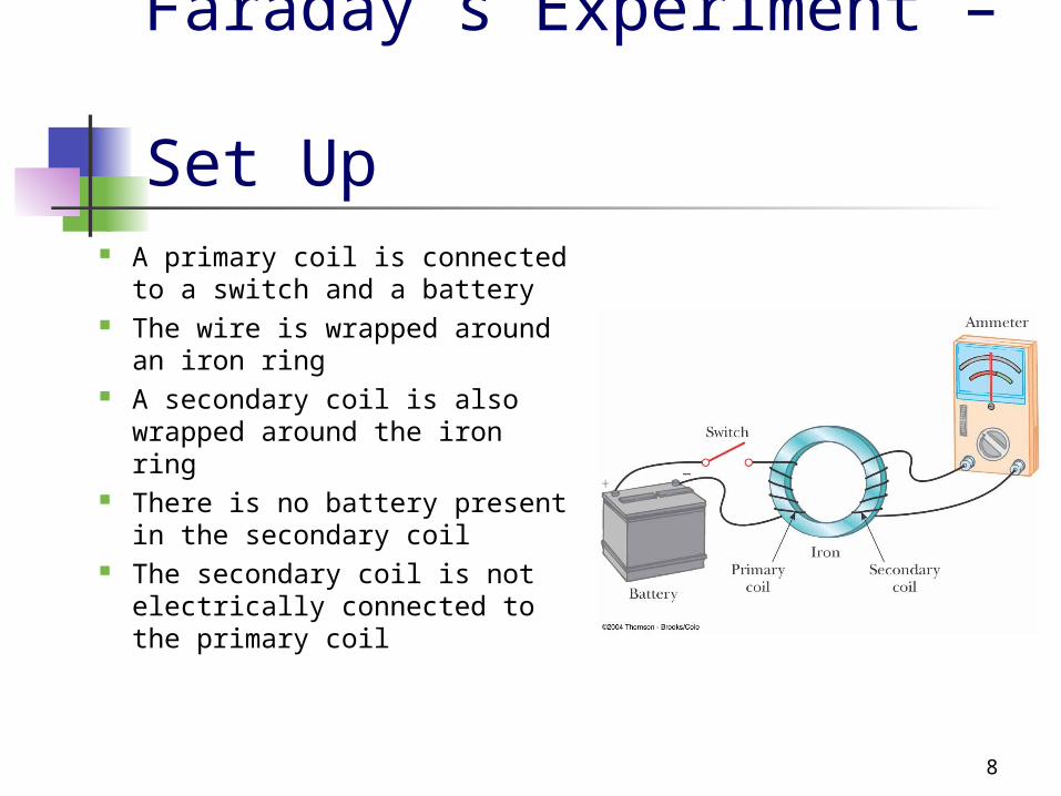
Faraday’s Experiment – Set Up
A primary coil is connected to a switch and a battery
The wire is wrapped around an iron ring
A secondary coil is also wrapped around the iron ring
There is no battery present in the secondary coil
The secondary coil is not electrically connected to the primary coil

9
Faraday’s Experiment – Findings
At the instant the switch is closed, the galvanometer (ammeter) needle deflects in one direction and then returns to zero
When the switch is opened, the galvanometer needle deflects in the opposite direction and then returns to zero
The galvanometer reads zero when there is a steady current or when there is no current in the primary circuit
10
Faraday’s Experiment – Conclusions
An electric current can be produced by a time-varying magnetic field This would be the current in the secondary circuit of this
experimental set-up The induced current exists only for a short time
while the magnetic field is changing This is generally expressed as: an induced emf is
produced in the secondary circuit by the changing magnetic field The actual existence of the magnetic field is not sufficient
to produce the induced emf, the field must be changing

11
Magnetic Flux To express
Faraday’s finding mathematically, the magnetic flux is used
The flux depends on the magnetic field and the area:
B d B A

12
Faraday’s Law – Statements Faraday’s Law of Induction states that
the emf induced in a circuit is equal to the time rate of change of the magnetic flux through the circuit
Mathematically,
Bd
dt
13
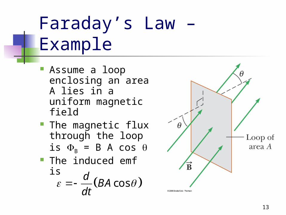
Faraday’s Law – Example Assume a loop
enclosing an area A lies in a uniform magnetic field
The magnetic flux through the loop is B = B A cos
The induced emf is cos
dBA
dt

14
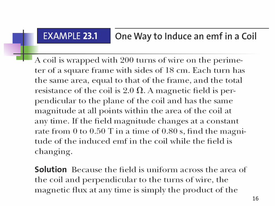
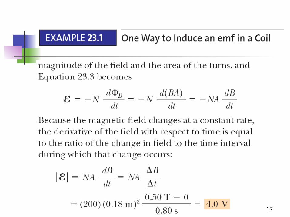
Ways of Inducing an emf The magnitude of the field can change
with time The area enclosed by the loop can
change with time The angle between the field and the
normal to the loop can change with time Any combination of the above can occur

15
Applications of Faraday’s Law – Pickup Coil
The pickup coil of an electric guitar uses Faraday’s Law
The coil is placed near the vibrating string and causes a portion of the string to become magnetized
When the string vibrates at the some frequency, the magnetized segment produces a changing flux through the coil
The induced emf is fed to an amplifier
16
17

18

19

20
23.2 Motional emf A motional emf is one
induced in a conductor moving through a magnetic field
The electrons in the conductor experience a force that is directed along l
B q F v B

21
Motional emf, cont Under the influence of the force, the electrons
move to the lower end of the conductor and accumulate there
As a result of the charge separation, an electric field is produced inside the conductor and gives rise to an electric force on the electrons
The charges accumulate at both ends of the conductor until the electric and magnetic forces are balanced
22
Motional emf, final For balance, q E = q v B or E = v B A potential difference V=vBl between the
two ends of the conductor is maintained as long as the conductor continues to move through the uniform magnetic field
If the direction of the motion is reversed, the polarity of the potential difference is also reversed
23
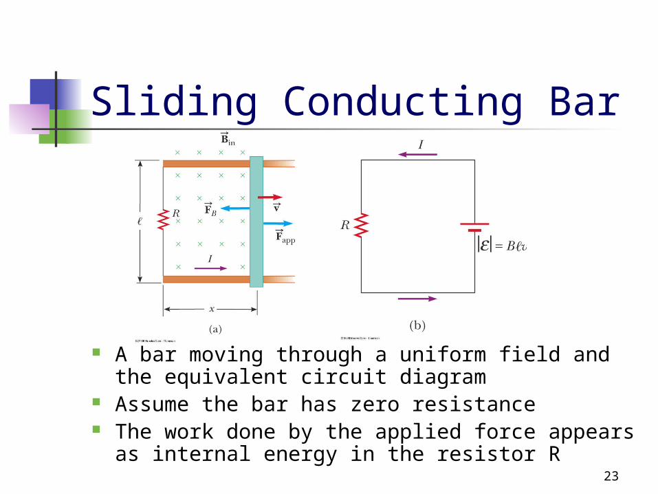
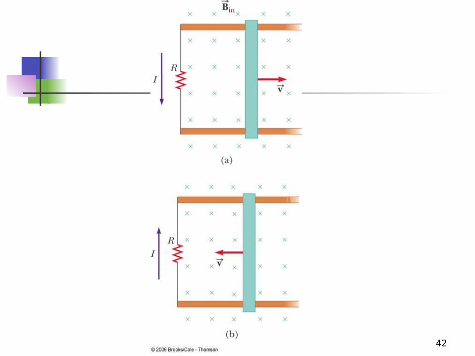
Sliding Conducting Bar
A bar moving through a uniform field and the equivalent circuit diagram
Assume the bar has zero resistance The work done by the applied force appears as
internal energy in the resistor R

24
Sliding Conducting Bar, cont The induced emf is
Since the resistance in the circuit is R, the current is
Bd dxB B v
dt dt
B vI
R R
25
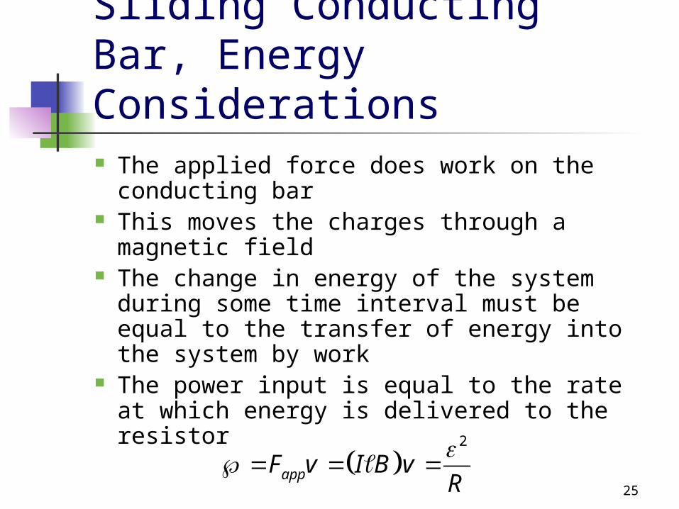
Sliding Conducting Bar, Energy Considerations The applied force does work on the
conducting bar This moves the charges through a magnetic
field The change in energy of the system during
some time interval must be equal to the transfer of energy into the system by work
The power input is equal to the rate at which energy is delivered to the resistor
2
appF v I B vR

26

27

28
29

30
31
32
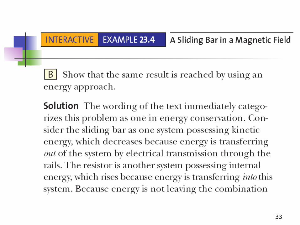
33

34

35

36
AC Generators Electric generators take
in energy by work and transfer it out by electrical transmission
The AC generator consists of a loop of wire rotated by some external means in a magnetic field

37
Induced emf In an AC Generator
The induced emf in the loops is
This is sinusoidal, with max = N A B
sin
BdN
dtNAB t

38
23.3 Lenz’ Law Faraday’s Law indicates the induced
emf and the change in flux have opposite algebraic signs
This has a physical interpretation that has come to be known as Lenz’ Law
It was developed by a German physicist, Heinrich Lenz
39
Lenz’ Law, cont Lenz’ Law states the polarity of the
induced emf in a loop is such that it produces a current whose magnetic field opposes the change in magnetic flux through the loop
The induced current tends to keep the original magnetic flux through the circuit from changing

40
Lenz’ Law – Example 1
When the magnet is moved toward the stationary loop, a current is induced as shown in a
This induced current produces its own magnetic field that is directed as shown in b to counteract the increasing external flux

41
Lenz’ Law – Example 2
When the magnet is moved away the stationary loop, a current is induced as shown in c
This induced current produces its own magnetic field that is directed as shown in d to counteract the decreasing external flux
42

43

44