chapter 23: series and parallel circuits
TRANSCRIPT
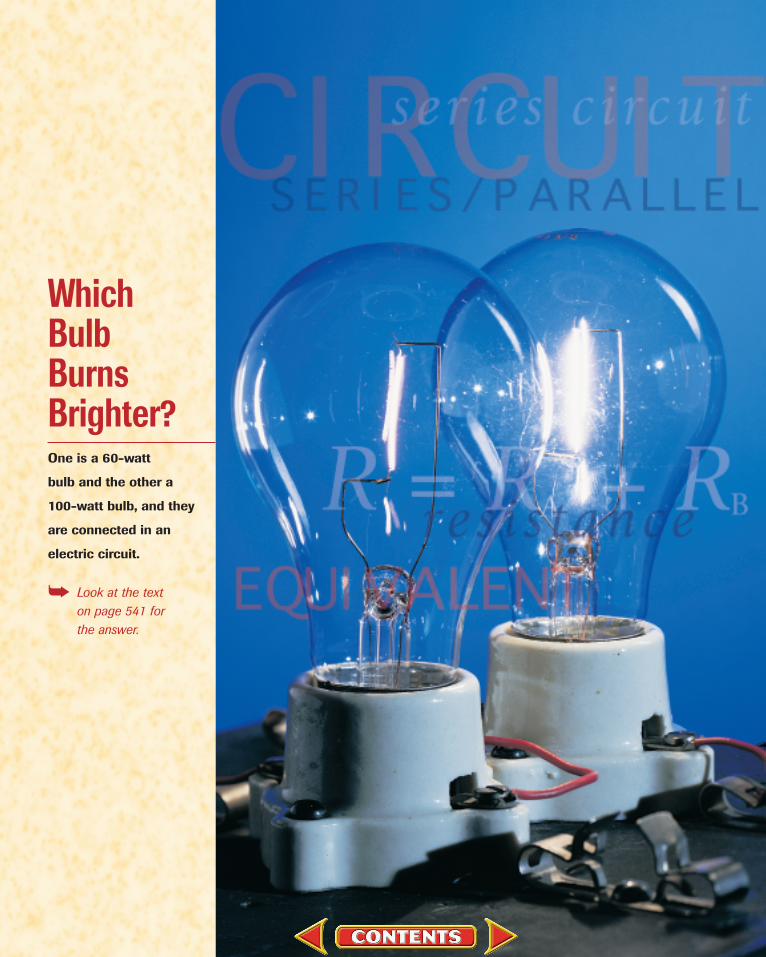
WhichBulbBurnsBrighter?One is a 60-watt
bulb and the other a
100-watt bulb, and they
are connected in an
electric circuit.
➥ Look at the text on page 541 for the answer.

Your desk needs to be well lit. You have a 100-watt lightbulband a 60-watt lightbulb available for your desk lamp.Which of the two lightbulbs would you choose? You know
a watt is a unit of power, so you might expect that a 100-wattlightbulb would always produce more light than a 60-watt bulb.But would it?
You’re shopping for a string of holiday lights for a party. Youfind a string of pumpkin lights with a tag that reads “If one goesout, the rest stay lit.” Why is this important? How are the lightsconnected to each other and the power source to make sure thatthe rest stay lit?
Does the type of electric circuit that connects the bulb make adifference? Suppose the lightbulbs are in a circuit unlike the par-allel circuit that normally connects lightbulbs in your home. Forexample, in the photo at the left, the bulbs are connected inseries. Does that make a difference? Can you figure out why? Toanswer these questions, you need to know how a series circuit dif-fers from a parallel circuit.
In Chapter 22, you studied circuits that had one source of elec-tric energy, for example, a battery and one device such as a motoror a lamp that converted the electric energy to another form. Butcircuits can be much more versatile than that. In this chapter,you’ll explore several ways in which devices may be connected inelectric circuits. By the end of this chapter, you’ll have no troubledeciding which of the two bulbs at the left is brighter and why therest of the bulbs stay lit.
Series and ParallelCircuits
WHAT YOU’LL LEARN• You will distinguish between
parallel and series circuitsand series-parallel combina-tions and solve problemsdealing with them.
• You will explain the functionof fuses, circuit breakers,and ground fault interrupters,and describe ammeters and voltmeters.
WHY IT’S IMPORTANT• Electrical circuits are the
basis of every electricaldevice, from electric lights tomicrowave ovens to comput-ers. Understanding circuitshelps you to use them, andto use them safely.
23CHAPTER
531
PHYSICSTo find out more about electrical circuits, visit the Glencoe ScienceWeb site at science.glencoe.com

If you have ever had the chance to explore rivers inthe mountains, such as the river shown below in
Figure 23–1, the following description will be familiar. From their sources high in the mountains, rivers make their wayto the plains below. No matter what path they take, the change in eleva-tion, from the mountaintop to the plain, is the same. Some rivers flow in asingle stream, tumbling through a series of rapids and over waterfalls.Other rivers split into two or more streams as they flow over a waterfall orthrough the rapids. Part of the river follows one path; other parts find dif-ferent routes. But no matter how many paths the water takes, the totalamount of water flowing down the mountain is the same, and the verticaldrop from mountaintop to plain is the same distance.
Mountain rivers can serve as a model for electric circuits. The distancethe water drops is similar to potential difference. The amount of waterflowing through the river each second is similar to current. Narrow rapidsare like a large resistance. But what is similar to a battery or generator?Just as in an electrical circuit, an energy source is needed to raise waterto the top of the mountain. As you learned in Earth science, the source ofenergy is the sun. Solar energy evaporates water from lakes and seas andforms clouds that release rain or snow to fall on the tops of mountains.Think about the mountain river model as you read about the current inelectrical circuits.
OBJ ECTIVES• Describe both a series
connection and a parallelconnection and state theimportant characteristics of each.
• Calculate current, voltagedrops, and equivalent resis-tance for devices connectedin series and in parallel.
• Describe a voltage dividerand solve problems involving one.
23.1 Simple Circuits
532 Series and Parallel Circuits
FIGURE 23–1 No matter whatpath the water of a river takesdown a mountain, the amount ofwater and the drop in elevationare the same.

Series CircuitsPat, Chris, and Ali were connecting two identical lamps to a battery
as illustrated in Figure 23–2. Before making the final connection to thebattery, their teacher asked them to predict the brightness of the twolamps. They knew that the brightness of a lamp depends on the currentflowing through it. Pat said that only the lamp closer to the + terminalof the battery would light because all the current would be convertedinto light. Chris said that the second lamp would light, but it would bedimmer than the other one because some electrical energy would bechanged into thermal and light energy. Consequently, there would beless electrical energy left for the second lamp. Ali said that both lampswould be equally bright because current is a flow of charge, and becausethe charge leaving the first lamp had nowhere else to go in the circuitexcept through the second lamp, the current would be the same in thetwo lamps. Who do you think is right?
If you consider the mountain river model for this circuit, you’ll seethat Ali is correct. Charge has only one path to follow. Recall from Chap-ter 20 that charge cannot be created or destroyed, so the same amountof charge must leave a circuit as enters the circuit. This means that thecurrent is the same everywhere in the circuit. If you connect threeammeters into a circuit as shown in Figure 23–3, they all have the samevalue. A circuit such as this, in which all current travels through eachdevice, is called a series circuit.
But how could you answer Chris? If the current is the same, whatchanges in the lamp to produce the thermal and light energy? Recall thatpower, the rate at which electrical energy is converted, is represented byP � IV. Thus, if there is a potential difference or voltage drop across thelamp, then electrical energy is being converted into another form. Theresistance of the lamp is defined as R � V/I. Thus, the potential differ-ence, also called the voltage drop, is V � IR.
What is the current in the series circuit? From the river model,you know that the sum of the drops in height at each rapid is equal tothe total drop from the top of the mountain to sea level. In the electri-cal circuit, the increase in voltage provided by the generator or otherenergy source, Vsource, is equal to the sum of voltage drops across thelamps A and B.
Vsource � VA � VB
Because the current, I, through the lamps is the same, VA � IRA andVB � IRB. Therefore, Vsource � IRA � IRB or Vsource � I(RA � RB).The current through the circuit is represented by the following.
I � �R
V
A
so�ur
Rce
B�
This equation applies to any number of resistances in series, not justtwo. The same current would exist with a single resistor, R, that has a
23.1 Simple Circuits 533
+–
RA
RB
Vsource
+
–
FIGURE 23–2 What is your prediction about the brightnessof the two lightbulbs?
FIGURE 23–3 The ammetersshow that in a series circuit thecurrent is the same everywhere.

resistance equal to the sum of the resistances of the two lamps. Such aresistance is called the equivalent resistance of the circuit. For resistorsin series, the equivalent resistance is the sum of all the individualresistances.
Equivalent Resistance for Resistors in Series R � RA � RB � . . .
Notice that the equivalent resistance is larger than any single resis-tance. Therefore, if the battery voltage doesn’t change, adding moredevices in series always decreases the current. To find the current, I,through a series circuit, first calculate the equivalent resistance, R, andthen use the following equation to calculate I.
Current I � �Vso
Rurce�
534 Series and Parallel Circuits
F.Y.I.Henry Cavendish used thedirect approach to measurethe strength of an electriccurrent. Lacking the appropriate instruments, he instead shocked himselfwith the current and thenestimated the pain.
Pocket LabSeries Resistance
Hook up a power supply, aresistor, and an ammeter in aseries circuit. Predict what willhappen to the current in thecircuit when a second, identicalresistor is added in series to thecircuit. Predict the new currentswhen the circuit contains threeand four resistors in series.Explain your prediction. Try it. Analyze and Conclude Makea data table to show yourresults. Briefly explain yourresults. (Hint: Include the ideaof resistance.)
1. Three 20-� resistors are connected in series across a 120-V generator. What is the equivalent resistance of the circuit? What is the current in the circuit?
2. A 10-� resistor, a 15-� resistor, and a 5-� resistor are connectedin series across a 90-V battery. What is the equivalent resistanceof the circuit? What is the current in the circuit?
3. Consider a 9-V battery in a circuit with three resistors connectedin series.a. If the resistance of one of the resistors increases, how will the
series resistance change?b. What will happen to the current?c. Will there be any change in the battery voltage?
4. A string of holiday lights has ten bulbs with equal resistancesconnected in series. When the string of lights is connected to a120-V outlet, the current through the bulbs is 0.06 A.a. What is the equivalent resistance of the circuit?b. What is the resistance of each bulb?
5. Calculate the voltage drops across the three resistors in problem 2, and check to see that their sum equals the voltage of the battery.
Practice Problems
Voltage drops in a series circuit In any circuit, the net change inpotential as current moves through it must be zero. This is because theelectrical energy source in the circuit, the battery or generator, raises thepotential. As current passes through the resistors, the potential drops anamount equal to the increase, and, therefore, the net change is zero.
The potential drop across each resistor in a series circuit can be cal-culated by rearranging the equation that defines resistance, R � V/I, to

23.1 Simple Circuits 535
solve for V, V � IR. First, find the equivalent resistance, R, in the circuitby calculating the sum of all the individual resistances. Then, to find thecurrent, which is the same everywhere in the circuit, use the equivalentresistance and the equation I � V/R, where V is the potential drop. Hav-ing determined the current in the circuit, multiply I by the resistance ofthe individual resistor to find the potential drop across that resistor.
An important application of series resistors is the voltage divider. Avoltage divider is a series circuit used to produce a voltage source ofdesired magnitude from a higher-voltage battery. Suppose you have a 9-V battery but need a 5-V potential source. A voltage divider can supplythis voltage. Consider the circuit shown in Figure 23–4. Two resistors,RA and RB, are connected in series across a battery of magnitude V. Theequivalent resistance of the circuit is R � RA � RB. The current, I, is rep-resented by the following equation.
I � �V
R� � �
RA �
V
RB�
The desired voltage, 5 V, is the voltage drop, VB, across resistor RB.
VB � IRB.
I is replaced by the preceding equation.
VB � IRB � ��RA �
V
RB�� RB
VB � �RA
V
�
RBRB
�
Voltage dividers are often used with sensors such as photoresistors.The resistance of a photoresistor depends upon the amount of light thatstrikes it. Photoresistors are made of semiconductors such as silicon,selenium, and cadmium sulfide. A typical photoresistor can have a resis-tance of 400 � when light strikes it, but 400 000 � when in the dark.The output voltage of a voltage divider that uses a photoresistordepends upon the amount of light striking the photoresistor sensor.This circuit can be used as a light meter, such as the one in Figure 23–5.In this device, an electronic circuit detects the potential difference andconverts it to a measurement of illuminance that can be read on the digital display.
RA
V I
RB
+
–VB
AmplifiedVoltmeter
Sensitivity adjustment(potentiometer)
Photoresister sensor
Light
Drycells
FIGURE 23–4 The values of RAand RB are chosen such that thevoltage drop across RB is thedesired voltage.
FIGURE 23–5 The output voltageof this voltage divider dependsupon the amount of light strikingthe photoresistor sensor. This isthe basis for the light metershown at left.
The Inverse KeyBecause multiplication is theinverse of division, you can usethe inverse key, 1/x, to performcalculation without having toreenter numbers.
�40
(90
V�
)(�
50500�
0)�
�
Keys Display
900
1.11 . . . �03
5
Answer 5 V
�500�9�
�1/x
�500�400

536 Series and Parallel Circuits
Voltage Drops in a Series CircuitTwo resistors, 47.0-� and 82.0-�, are connected in series across
a 45.0-V battery.
a. What is the current in the circuit?
b. What is the voltage drop across each resistor?
c. The 47.0-� resistor is replaced by a 39.0-� resistor. Will the currentincrease, decrease, or remain the same?
d. What will happen to the voltage drop across the 82.0-� resistor?
Sketch the Problem• Draw a schematic of the circuit. • Include an ammeter and voltmeters.
Calculate Your AnswerKnown: Unknown:
Vsource � 45.0 V I � ?
RA � 47.0 � VA � ?
RB � 82.0 � VB � ?
effects of changing RA
Check Your Answer• Are the units correct? Current, A � V/�, voltage, V � A�.• Is the magnitude realistic? Numerically, R > V, so I < 1.
R decreases so I increases. VB changes because it depends on I.
Strategy:
a. To determine the current, first find the equivalent resistance.
b. Use V � IR for each resistor.
c. Calculate current again using RA as 39.0 �.
d. Determine new voltage drop.
Calculations:
R � RA � RB
I � �Vso
Rurce� � �
R
V
A
so�ur
Rce
B�
I ��47.0 �
45
�
.0
8
V
2.0 ��� 0.349 �
VA � IRA � (0.349)(47.0 �) � 16.4 V
VB � IRB � (0.349)(82.0 �) � 28.6 V
I � �R
V
A
so�ur
Rce
B� ��
39.0 �
45
�
.0
8
V
2.0 ��� 0.372 �
The current will increase.
VB � IRB � (0.372)(82.0 �) � 30.5 V
The voltage will increase.
+
–
RA
RB
A
VA
VB
V
Example Problem

Voltage DividerA 9.0-V battery and two resistors, 400 � and 500 �, are connected
as a voltage divider. What is the voltage across the 500-� resistor?
Sketch the Problem• Draw the battery and resistors in a series circuit.
Calculate Your AnswerKnown:
Vsource � 9.0 V
RA � 400 �
RB � 500 �
Unknown:
VB � ?
Check Your Answer• Are the units correct? V � V �/�.• Is the magnitude realistic? The voltage drop is less than the battery
voltage. Because 500 � is more than half of the equivalent resistance,the voltage drop is more than half the battery voltage.
23.1 Simple Circuits 537
+
RA
I
RB VB
–V
Strategy:
Write the expression for thecurrent through the circuit.
Determine equivalentresistance, R.
Use voltage drop equation todetermine VB.
Calculations:
I � �Vso
Rurce�
R� RA � RB
VB � IRB ��(V
Rso
A
ur�ce)
R
(R
B
B)�
VB � � 5 V(9.0 V)(500 �)
���400 � � 500 �
6. A 20.0-� resistor and a 30.0-� resistor are connected in seriesand placed across a 120-V potential difference.a. What is the equivalent resistance of the circuit?b. What is the current in the circuit?c. What is the voltage drop across each resistor?d. What is the voltage drop across the two resistors together?
7. Three resistors of 3.0 k�, 5.0 k�, and 4.0 k� are connected inseries across a 12-V battery.a. What is the equivalent resistance?b. What is the current through the resistors?c. What is the voltage drop across each resistor?d. Find the total voltage drop across the three resistors.
F.Y.I.The largest voltages in yourhome are in your televisionset, where 15 000 V to 20 000 V are common. The largest currents arelikely to be the 40 A in anelectric range.
Example Problem
Practice Problems
Continued on next page

Parallel CircuitsLook at the circuit shown in Figure 23–6. How many current paths
are there? The current from the generator can go through any of the threeresistors. A circuit in which there are several current paths is called a parallel circuit. The three resistors are connected in parallel; both endsof the three paths are connected together. In the mountain river modelfor circuits, such a circuit is illustrated by three paths for the water over awaterfall. Some paths may have a large flow of water, others a small flow.The sum of the flows, however, is equal to the total flow of water over thefalls. In addition, it doesn’t matter which channel the water flowsthrough because the drop in height is the same. Similarly, in a parallelelectrical circuit, the total current is the sum of the currents through eachpath, and the potential difference across each path is the same.
What is the current through each resistor? It depends upon the indi-vidual resistance. For example, in Figure 23–7, the potential differenceacross each resistor is 120 V. The current through a resistor is given byI � V/R, so you can calculate the current through the 24-� resistor asI � (120V)/(24 �) � 5 A. Calculate the currents through the other tworesistors. The total current through the generator is the sum of the cur-rents through the three paths, in this case, 38 A.
What would happen if the 6-� resistor were removed from the cir-cuit? Would the current through the 24-� resistor change? That currentdepends only upon the potential difference across it and its resistance,and neither has changed, so the current is unchanged. The same is true
538 Series and Parallel Circuits
8. A photoresistor is used in a voltage divider as RB. V � 9.0 V andRA � 500 �.a. What is the output voltage, VB, across RB, when a bright light
strikes the photoresistor and RB � 475 �?b. When the light is dim, RB � 4.0 k�. What is VB?c. When the photoresistor is in total darkness, RB � 0.40 M�
(0.40 � 106 �). What is VB?9. A student makes a voltage divider from a 45-V battery, a 475-k�
(475 � 103 �) resistor, and a 235-k� resistor. The output ismeasured across the smaller resistor. What is the voltage?
Generator
RC
RB
RA
120 V
38 A
5 A
24 � 9 �120 V
A
A
V
13 AA
V 6 �120 V
20 A
120 V
A
V
FIGURE 23–6 The parallel pathsfor current in this diagram areanalogous to the paths that a river may take down the mountain.
FIGURE 23–7 In a parallel circuit, the reciprocal of the totalresistance is equal to the sum ofthe reciprocals of the individualresistances.

for the current through the 9-� resistor. The branches of a parallel circuit are independent of each other. The total current through the gen-erator, however, would change, and the sum of the currents in thebranches would then be 18 A.
How can you find the equivalent resistance of a parallel circuit? InFigure 23–7, the total current through the generator is 38 A. A singleresistor that would have a 38-A current when 120 V were placed acrossit would be represented by the following equation.
R � �V
I� � �
1
3
2
8
0
A
V� � 3.2 �
Notice that this resistance is smaller than that of any of the three resis-tors in parallel. Placing two or more resistors in parallel always decreasesthe equivalent resistance of a circuit. The resistance decreases becauseeach new resistor provides an additional path for current, increasing thetotal current while the potential difference remains unchanged.
To calculate the equivalent resistance of a parallel circuit, first notethat the total current is the sum of the currents through the branches. IfIA, IB, and IC are the currents through the branches and I is the total cur-rent, then I � IA � IB � IC.
The potential difference across each resistor is the same, so the cur-rent through each resistor, for example, RA, can be found from IA �
V/RA. Therefore, this becomes the equation for the sum of the currents:
�V
R� � �
R
V
A� � �
R
V
B� � �
R
V
C�
Dividing both sides of the equation by V provides an equation for theequivalent resistance of the three parallel resistors.
Equivalent Resistance for Resistors in Parallel �R
1� � �
R
1
A� � �
R
1
B� � �
R
1
C�
This equation can be used for any number of resistors in parallel.
23.1 Simple Circuits 539
Equivalent Resistance and Current in a Parallel Circuit
Three resistors, 60.0 �, 30.0 �, and 20.0 �, are connected in parallel across a 90.0-V battery.
a. Find the current through each branch of the circuit.
b. Find the equivalent resistance of the circuit.
c. Find the current through the battery.
Sketch the Problem• Draw a schematic of the circuit. • Include ammeters to show the paths of the currents.
90.0 V
60.0 � 30.0 � 20.0 �
IA IB ICA
A A A
Pocket LabParallel Resistance
Hook up a power supply, aresistor, and an ammeter in aseries circuit. Predict what willhappen to the current in thecircuit when a second, identicalresistor is added in parallel tothe first. Predict the new cur-rents when the circuit containsthree and four resistors in parallel. Explain your prediction.Try it. Analyze and Conclude Makea data table to show yourresults. Briefly explain yourresults. (Hint: Include the ideaof resistance.)
Example Problem
Continued on next page

540 Series and Parallel Circuits
Calculate Your AnswerKnown: Unknown:
RA � 60.0 � RC � 20.0 � IA � ? IC � ? R � ?
RB � 30.0 � V � 90.0 V IB � ? I � ?
Check Your Answer• Are your units correct? Currents are in amps, resistances are in ohms.• Do the signs make sense? All are positive, as they should be.• Is the magnitude realistic? IA � IB � IC � I
Calculations:
IA � �R
V
A� � �
6
9
0
0
.
.
0
0
�
V� � 1.50 A
IB � �R
V
B� � �
3
9
0
0
.
.
0
0
�
V� � 3.00 A
IC � �R
V
C� � �
2
9
0
0
.
.
0
0
�
V� � 4.50 A
�R
1�� �
R
1
A� � �
R
1
B� � �
R
1
C�
�R
1�� �
60.
1
0 �� � �
30.
1
0 �� � �
20.
1
0 �� � 0.100 ��1
R � 10.0 �
I � �V
R� � �
1
9
0
0
.
.
0
0
�
V� � 9.00 A
Strategy:
a. The voltage across each resistor is the
same, so use I � �V
R� for each branch.
b. Use the equivalent resistance equationfor parallel circuits.
c. Use I � �V
R� to find the total current.
10. Three 15-� resistors are connected in parallel and placed acrossa 30-V battery.a. What is the equivalent resistance of the parallel circuit?b. What is the current through the entire circuit?c. What is the current through each branch of the circuit?
11. A 120.0-� resistor, a 60.0-� resistor, and a 40.0-� resistor areconnected in parallel and placed across a 12.0-V battery.a. What is the equivalent resistance of the parallel circuit?b. What is the current through the entire circuit?c. What is the current through each branch of the circuit?
12.Suppose one of the 15.0-� resistors in problem 10 is replacedby a 10.0-� resistor.a. Does the equivalent resistance change? If so, how?
Practice Problems
23.1 Simple Circuits 541
b. Does the amount of current through the entire circuit change?In what way?
c. Does the amount of current through the other 15.0-� resistors change? In what way?
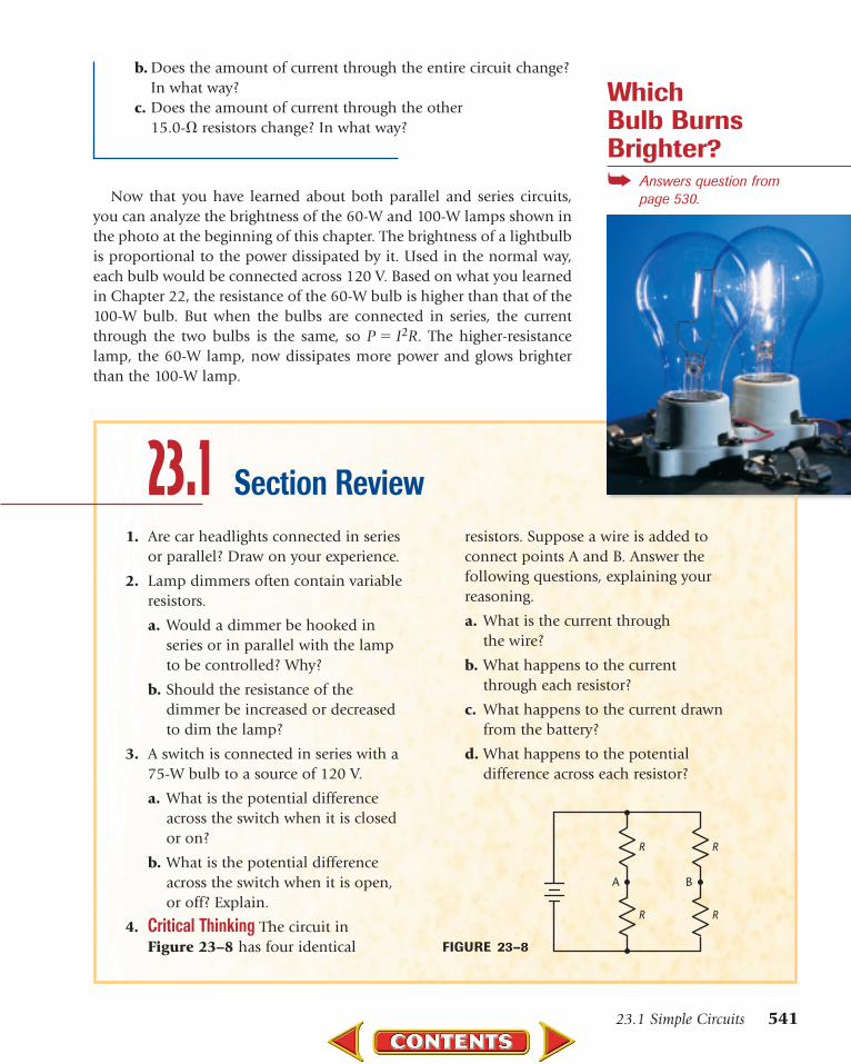
Now that you have learned about both parallel and series circuits,you can analyze the brightness of the 60-W and 100-W lamps shown inthe photo at the beginning of this chapter. The brightness of a lightbulbis proportional to the power dissipated by it. Used in the normal way,each bulb would be connected across 120 V. Based on what you learnedin Chapter 22, the resistance of the 60-W bulb is higher than that of the100-W bulb. But when the bulbs are connected in series, the currentthrough the two bulbs is the same, so P � I2R. The higher-resistancelamp, the 60-W lamp, now dissipates more power and glows brighterthan the 100-W lamp.
Section Review1. Are car headlights connected in series
or parallel? Draw on your experience.
2. Lamp dimmers often contain variableresistors.
a. Would a dimmer be hooked inseries or in parallel with the lampto be controlled? Why?
b. Should the resistance of the dimmer be increased or decreasedto dim the lamp?
3. A switch is connected in series with a75-W bulb to a source of 120 V.
a. What is the potential differenceacross the switch when it is closedor on?
b. What is the potential differenceacross the switch when it is open,or off? Explain.
4. Critical Thinking The circuit inFigure 23–8 has four identical
resistors. Suppose a wire is added toconnect points A and B. Answer thefollowing questions, explaining yourreasoning.
a. What is the current through the wire?
b. What happens to the currentthrough each resistor?
c. What happens to the current drawnfrom the battery?
d. What happens to the potential difference across each resistor?
23.1
R
A
R
R
B
R
FIGURE 23–8
Which Bulb Burns Brighter?➥ Answers question from
page 530.
You have already learned some of the elementsof household wiring circuits. It’s important to
understand the requirements and limitations ofthese systems. Above all, it is important to be awareof the safety measures that must be practiced to prevent accidents.
Safety DevicesIn an electric circuit, fuses and circuit breakers are switches that act as
safety devices. They prevent circuit overloads that can occur when toomany appliances are turned on at the same time or a short circuit occursin one appliance. When appliances are connected in parallel, each addi-tional appliance placed in operation reduces the equivalent resistance inthe circuit and causes more current through the wires. The additionalcurrent may produce enough thermal energy (P � I2R) to melt insula-tion on the wires and cause a short circuit in the wires or even a fire.
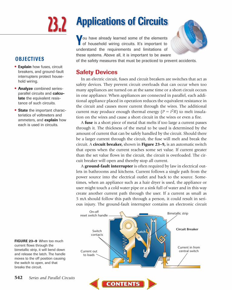
A fuse is a short piece of metal that melts if too large a current passesthrough it. The thickness of the metal to be used is determined by theamount of current that can be safely handled by the circuit. Should therebe a larger current through the circuit, the fuse will melt and break thecircuit. A circuit breaker, shown in Figure 23–9, is an automatic switchthat opens when the current reaches some set value. If current greaterthan the set value flows in the circuit, the circuit is overloaded. The cir-cuit breaker will open and thereby stop all current.
A ground-fault interrupter is often required by law in electrical out-lets in bathrooms and kitchens. Current follows a single path from thepower source into the electrical outlet and back to the source. Some-times, when an appliance such as a hair dryer is used, the appliance oruser might touch a cold water pipe or a sink full of water and in this waycreate another current path through the user. If a current as small as5 mA should follow this path through a person, it could result in seri-ous injury. The ground-fault interrupter contains an electronic circuit
OBJ ECTIVES• Explain how fuses, circuit
breakers, and ground-faultinterrupters protect house-hold wiring.
• Analyze combined series-parallel circuits and calcu-late the equivalent resis-tance of such circuits.
• State the important charac-teristics of voltmeters andammeters, and explain howeach is used in circuits.
23.2 Applications of Circuits
542 Series and Parallel Circuits
Current in fromcentral switch
Bimetallic strip
Switchcontacts
LatchCircuit Breaker
Current outto loads
On-offreset switch handle
FIGURE 23–9 When too muchcurrent flows through thebimetallic strip, it will bend downand release the latch. The handlemoves to the off position causingthe switch to open, and thatbreaks the circuit.

543
that detects small differences in current caused by an extra current pathand opens the circuit, thereby preventing dangerous shocks.
Electric wiring in homes uses parallel circuits, such as the one dia-grammed in Figure 23–10, so that the current in any one circuit doesnot depend upon the current in the other circuits. The current in adevice that dissipates power, P, when connected to a voltage source, V, isrepresented by I � P/V. Suppose, that in the schematic diagram shownin Figure 23–10, a 240-W television is plugged into a 120-V outlet. Thecurrent that flows is represented by I � (240 W)/(120 V) � 2 A. Then, a720-W curling iron is plugged in. The current through the curling ironis I � (720 W)/(120 V) � 6 A. Finally, a 1440-W hair dryer is pluggedin. The current through the hair dryer is I � (1440 W)/(120 V) � 12 A.
The current through these three appliances can be found by consider-ing them as resistors in a parallel circuit in which the current througheach appliance is independent of the others. The value of the resistanceis found by calculating the current the appliance draws and then usingthe equation R � V/I. The equivalent resistance of the three appliances is
�R
1� � �
10
1
�� � �
20
1
�� � �
60
1
�� � �
6
1
��
R � 6 �.
The 15-A fuse is connected in series with the power source so theentire current passes through it. The current through the fuse is
I � �V
R� � �
1
6
20
�
V� � 20 A.
The 20-A current exceeds the rating of the 15-A fuse, so that the fuse willmelt, or blow, cutting off current to the entire circuit.
A short circuit occurs when a circuit is formed that has a very lowresistance. The low resistance causes the current to be very large. If therewere no fuse or circuit breaker, such a large current could easily start afire. A short circuit can occur if the insulation on a lamp cord becomesold and brittle. The two wires in the cord could accidentally touch. Theresistance of the wire might be only 0.010 �. When placed across 120 V,this resistance would result in the following current.
I � �V
R� � �
0
1
.0
2
1
0
0
V
�� � 12 000 A
120 V
15 A fuse
HELP WANTEDELECTRICIANElectrical contractor needselectricians who have suc-cessfully completed a 5-yearapprenticeship program con-ducted by a union or profes-sional builder’s association.You must be a high schoolgrad, be in good physicalcondition, have excellentdexterity and color vision,and be willing to work whenand where there is work. Youwill do all aspects of the job,including reading blueprints,dealing with all types ofwires, conduits, and equip-ment. Safety and qualitywork must be your highestpriorities. For informationcontact:International Brotherhood ofElectrical Workers1125 15th Street, N.W.Washington, DC 20005
23.2 Applications of Circuits
FIGURE 23–10 This parallelwiring arrangement permits theuse of more than one appliancesimultaneously, but if all threeappliances are used at once, thefuse could melt.

Such a current would cause a fuse or a circuit breaker to open the circuitimmediately, thereby preventing the wires from becoming hot enoughto start a fire.
Combined Series-Parallel CircuitsHave you ever noticed the light in your bathroom dim when you
turned on a hair dryer? The light and the hair dryer were connected inparallel across 120 V. This means that the current through the lampshould not have changed when you plugged in the dryer. Yet the lightdimmed, so the current must have changed. The dimming occurredbecause the house wiring had a small resistance in series with the parallel circuit. This is a combination series-parallel circuit. The fol-lowing is a strategy for analyzing such circuits. Refer to Figure 23–11which illustrates the procedure described in steps 1, 2, and 3 of theProblem Solving Strategy.
Series-Parallel Circuits1. Draw a schematic diagram of the circuit.2. Find any parallel resistors. Resistors in parallel have separate
current paths. They must have the same potential differencesacross them. Calculate the single equivalent resistance thatcan replace them. Draw a new schematic using that resistor.
3. Are any resistors (including the equivalent resistor) now inseries? Resistors in series have one and only one currentpath through them. Calculate a single new equivalent resis-tance that can replace them. Draw a new schematic diagramusing that resistor.
4. Repeat steps 2 and 3 until you can reduce the circuit to a sin-gle resistor. Find the total circuit current. Then go backwardsthrough the circuits to find the currents through and the voltages across individual resistors.
60 V
RA 8 �
30 �
IA
IB
RB
20 �
RC = =IC
RA 8 �
RBC
12 �
VA
VPR
20 �
FIGURE 23–11 Use these diagramsas you study the following ProblemSolving Strategy.
544 Series and Parallel Circuits

ProblemSuppose that three identical lamps are con-nected to the same power supply. Can a cir-cuit be made such that one lamp is brighterthan the others and stays on if either of theothers is loosened in its socket?
HypothesisOne lamp should be brighter than the othertwo and remain at the same brightness wheneither of the other two lamps is loosened inits socket so that it goes out.
Possible Materialspower supply with variable voltagewires with clips3 identical lamps and sockets
Plan the Experiment1. Sketch a series circuit and predict the
relative brightness of each lamp. Predictwhat would happen to the other lampswhen one is loosened so that it goes out.
2. Sketch a parallel circuit and predict therelative brightness of each lamp. Predictwhat would happen to the other lampswhen one is loosened so that it goes out.
3. Draw a combination circuit. Label thelamps A, B, and C. Would the bulbs havethe same brightness? Predict what wouldhappen to the other two lamps when eachlamp in turn is loosened so that it goes out.
4. Check the Plan Show your circuits andpredictions to your teacher before starting to build the circuits.
5. When you have completed the lab, disposeof or recycle appropriate materials. Put awaymaterials that can be reused.
Analyze and Conclude1. Interpreting Data Did the series circuit
meet the requirements? Explain.
2. Interpreting Data Did the parallel circuitmeet either of the requirements? Explain.
3. Formulating Hypotheses Explain thecircuit that solved the problem in terms of current.
4. Formulating Hypotheses Use the defi-nition of resistance to explain why onelamp was brighter and the other two wereequally dim.
5. Making Predictions Predict how thevoltages would compare when measuredacross each lamp in the correct circuit.
6. Testing Conclusions Use a voltmeter tocheck your prediction.
Apply1. Can one wall switch control several lights
in the same room? Are the lamps in paral-lel or series? Are the switches in parallelor series with the lamps? Explain.
Circuits
23.2 Applications of Circuits 545

546 Series and Parallel Circuits
Series-Parallel CircuitA hair dryer with a resistance of 12.0 � and a lamp with a resistance
of 125 � are connected in parallel to a 125-V source through a 1.50-�resistor in series.
a. Find the current through the lamp when the hair dryer is off.
b. Find the current when the hair dryer is on.
c. Explain why the lamp dims when the hair dryer is on.
Sketch the Problem• Draw a diagram of the simple series circuit when the dryer is off. • Draw the series-parallel circuit including the dryer and lamp. • Replace RA and RB with a single equivalent resistance, RP.
Calculate Your AnswerKnown: Unknown:RA � 125 � IA1 � ?
RB � 12.0 � R � ?
RC � 1.50 � IA2 � ?
Vsource � 125 V I2 � ?V
IA1
RA
RC
IA2
IA
RA
RC RC
RRB
Strategy:
a. When the hair dryer is off, the circuit is asimple series circuit.
b. Find the equivalent resistance for parallel circuit.
Find the equivalent resistance for entire circuit.
Use equivalent resistance to determine thecurrent when the hair dryer is on.
c. The greater current when the hair dryer is on means a greater voltage drop acrossRC, which causes less voltage across RA. A decrease in voltage means currentdecreases, which is less power.
Calculations:
IA1 � �RA �
V
RC� ��
125 �
12
�
5
1
V
.50 ��� 0.988 A
�R
1
p� � �
R
1
A� � �
R
1
B�, so Rp � �
RA
RA�
RBRB
�
R � RC � Rp � RC � �RA
RA�
RBRB
�
R �1.50 � ��(
1
1
2
2
5
5
�
�
�
)(1
1
2
2
.0
.0
�
�
)�� 12.5 �
IA2 � �Vso
Rurce� � �
1
1
2
2
.
5
5
V
�� � 1.00 � 101 A
VC � IRC � (1.00 � 101 A)(1.50 �) � 15.0 V
VA � Vsource � VC � 125 V � 15.0 V
� 1.10 � 102 V
IA � �V
RA
A� ��1.10
12
�
5
1
�
02 V�� 0.880 A
Example Problem
Current drops from 0.988 A to 0.880 A. Power, P � I2R, is smaller, consequently the light dims.

13.Two 60-� resistors are connected in parallel. This parallelarrangement is connected in series with a 30-� resistor. Thecombination is then placed across a 120-V battery.a. Draw a diagram of the circuit.b. What is the equivalent resistance of the parallel portion of
the circuit?c. What single resistance could replace the three original resistors?d. What is the current in the circuit?e. What is the voltage drop across the 30-� resistor?f. What is the voltage drop across the parallel portion of
the circuit?g. What is the current in each branch of the parallel portion of
the circuit?
23.2 Applications of Circuits 547
0.01 �Ammeter
0.01 ��10 ��10 �=20.01 �
20 V
RA10.00 �
RB10.00 �
FIGURE 23–12 An ammetermeasures current and so it isalways placed in series in a circuit.
Check Your Answer• Are the units correct? Current is in amps, potential drops are in volts.• Is the magnitude realistic? Decreased parallel resistance increases
the current, causing a voltage drop in the series resistor. This leavesless voltage across the combination, so the current is smaller.
Pocket LabAmmeter Resistance
Design an experiment using apower supply, a voltmeter, anammeter, a resistor, and somewires to determine the resis-tance of the ammeter. Make asketch of your setup and includemeasurements and equations. Communicating Results Whatis the resistance of the ammeter?Be prepared to present yourexperiment to the class.
Practice Problems
Ammeters and VoltmetersAn ammeter is used to measure the current in any branch or part of
a circuit. If, for example, you want to measure the current through aresistor, you would place an ammeter in series with the resistor. Thisrequires opening a current path and inserting an ammeter. The use of anammeter should not change the current in the circuit you wish to mea-sure. Because current would decrease if the ammeter increased the resis-tance in the circuit, the resistance of an ammeter should be as low aspossible. Figure 23–12 shows a real ammeter as an ideal, zero-resis-tance meter placed in series with a 0.01-� resistor. The ammeter resis-tance is much smaller than the values of the resistors. The currentdecrease would be from 1.0 A to 0.9995 A, too small to notice.
Another instrument, called a voltmeter, is used to measure the voltagedrop across some part of a circuit. To measure the potential drop across aresistor, connect the voltmeter in parallel with the resistor. A voltmetershould have a very high resistance so that it causes the smallest possiblechange in currents or voltages in the circuit. Consider the circuit shown inFigure 23–13. A typical inexpensive voltmeter consists of an ideal, zero-resistance meter in series with a 10-k� resistor. When it is connected inparallel with RB, the equivalent resistance of the combination is smallerthan RB alone. Thus, the total resistance of the circuit decreases, increasing

the current. RA has not changed, but the current through it has increased,increasing the potential drop across it. The battery, however, holds thepotential drop across RA and RB constant. Thus, the potential drop acrossRB must decrease. The result of connecting a voltmeter across a resistor isto lower the potential drop across it. The higher the resistance of the volt-meter, the smaller the voltage change. Using a voltmeter with a 10 000-�resistance changes the voltage across RB from 10 V to 9.9975 V, too smalla change to detect. Modern electronic multimeters have even higher resis-tances, 107 �, and so produce even smaller changes.
548 Series and Parallel Circuits
Section Review1. Consider the circuit in Figure 23–14
made with identical bulbs.
a. Compare the brightness of the three bulbs.
b. What happens to the brightness ofeach bulb when bulb 1 is unscrewedfrom its socket? What happens to thethree currents?
c. Bulb 1 is screwed in again and bulb 3 isunscrewed. What happens to the bright-ness of each bulb? What happens to thethree currents?
d. What happens to the brightness of eachbulb if a wire is connected betweenpoints B and C?
e. A fourth bulb is connected in parallelwith bulb 3 alone. What happens tothe brightness of each bulb?
2. Research and describe the connectionbetween the physics of circuits and future careers.
3. Critical Thinking In the circuit inFigure 23–14, the wire at point C is broken and a small resistor is inserted in series with bulbs 2 and 3. What happens to the brightness of the two bulbs? Explain.
23.2
V
A
B
l2
l3
l1
1 2
3
C
A
A
A
20 V
10.00 �
10 k�
Voltmeter
RA
RB10.00 �
FIGURE 23–13 A laboratoryvoltmeter such as this one mea-sures potential difference. Volt-meters are placed in parallel.
FIGURE 23–14

23.2 Applications of Circuits 549
Thinking Critically1. Circuit breakers are
automatic switches.Explain why this is so.
2. Why must the contactsin a switch be metal?Why are switch handlesoften plastic?
Electric SwitchAn electric switch is a device that is used to interrupt,complete, or divert an electrical current in a circuit.Switches are found on everything from hair dryers andtoaster ovens, to calculators and video games, to com-puters and airplane instrument panels. Some switchesare simple mechanical switches. In certain devices,such as computers, however, mechanical switches aretoo slow and are replaced by electronic switches madefrom semiconducting materials.
Probably the most common type of switch is themechanical switch you use to operate the small appli-ances and lights in your home or school. The switchshown below is a snap-action toggle switch typicallyused to turn lights off and on.
OFFOFF
Contacts
Handle
Wall plate
Grounding wire
Incoming current
3
12
4
Insulated casing
5
3
The insulated handle of a snap-action toggle switch can be flippedin either of two positions–off or on.
2. When the handle is in the offposition, as it is in this diagram,metal contacts within the switchare separated, interrupting thepath of the current.
When the handle is in the on posi-tion, the metal contacts, which arelinked by wires, come together tocomplete the circuit.
1
2
5
One wire leads to a grounding loca-tion. Then if a problem occurs withthe wires or switch contacts, the cur-rent is routed to the ground, not tothe person touching the switch.
The switch casing is insulated, soif a wire becomes loose or frayedand touches the casing, currentwill not flow.
4

CHAPTER 23 REVIEW
550 Series and Parallel Circuits
Key Terms
23.1• series circuit• equivalent
resistance• voltage divider• parallel circuit
23.2• fuse• circuit breaker• ground-fault
interrupter• short circuit• combination
series-parallelcircuit
• ammeter• voltmeter
Summary
Key Equations
23.1
Reviewing Concepts
23.1 Simple Circuits• The current is the same everywhere in
a simple series circuit.• The equivalent resistance of a series
circuit is the sum of the resistances ofits parts.
• The sum of the voltage drops acrossresistors in series is equal to the potential difference applied across the combination.
• A voltage divider is a series circuit usedto produce a voltage source from ahigher-voltage battery.
• The voltage drops across all branches of a parallel circuit are the same.
• In a parallel circuit, the total current is equal to the sum of the currents inthe branches.
• The reciprocal of the equivalent resis-tance of parallel resistors is equal to the sum of the reciprocals of the indi-vidual resistances.
• If any branch of a parallel circuit isopened, there is no current in that
branch. The current in the other branches is unchanged.
23.2 Applications of Circuits• A fuse or circuit breaker, placed in series
with appliances, creates an open circuitwhen dangerously high currents flow.
• A complex circuit is often a combina-tion of series and parallel branches.Any parallel branch is first reduced to asingle equivalent resistance. Then anyresistors in series are replaced by a sin-gle resistance.
• An ammeter is used to measure the cur-rent in a branch or part of a circuit. Anammeter always has a low resistanceand is connected in series.
• A voltmeter measures the potential dif-ference (voltage) across any part orcombination of parts of a circuit. Avoltmeter always has a high resistanceand is connected in parallel with thepart of the circuit being measured.
R � RA � RB � . . . I � �Vso
Rurce� �
R
1� � �
R
1
A� � �
R
1
B� � �
R
1
C�
Section 23.11. Why is it frustrating when one bulb
burns out on a string of holiday treelights connected in series?
2. Why does the equivalent resistancedecrease as more resistors are addedto a parallel circuit?
3. Several resistors with different values are connected in parallel.
How do the values of the individualresistors compare with the equivalentresistance?
4. Why is household wiring done in parallel instead of in series?
5. Why is there a difference in totalresistance between three 60-� resis-tors connected in series and three 60-� resistors connected in parallel?

Chapter 23 Review 551
CHAPTER 23 REVIEW
6. Compare the amount of current entering ajunction in a parallel circuit with that leavingthe junction. Note: A junction is a point wherethree or more conductors are joined.
Section 23.27. Explain the function of a fuse in an
electric circuit.8. What is a short circuit? Why is a short circuit
dangerous?9. Why does an ammeter have a very low
resistance?10. Why does a voltmeter have a very high
resistance?11. How does the way in which an ammeter is con-
nected in a circuit differ from the way a volt-meter is connected?
Applying Concepts12. What happens to the current in the other two
lamps if one lamp in a three-lamp series circuitburns out?
13. Suppose that in the voltage divider inFigure 23–4, the resistor RA is made to be avariable resistor. What happens to the voltageoutput, VB, of the voltage divider if the resis-tance of the variable resistor is increased?
14. Circuit A contains three 60-� resistors in series.Circuit B contains three 60-� resistors in paral-lel. How does the current in the second 60-�resistor change if a switch cuts off the currentto the first 60-� resistor ina. circuit A?b. circuit B?
15. What happens to the current in the other twolamps if one lamp in a three-lamp parallel cir-cuit burns out?
16. An engineer needs a 10-� resistor and a 15-�resistor. But there are only 30-� resistors instock. Must new resistors be purchased?Explain.
17. If you have a 6-V battery and many 1.5-V bulbs,how could you connect them so that they light but do not have more than 1.5 V acrosseach bulb?
18. Two lamps have different resistances, one largerthan the other.
a. If they are connected in parallel, which isbrighter (dissipates more power)?
b. When connected in series, which is brighter?19. For each of the following, write the form of
circuit that applies: series or parallel.a. The current is the same throughout.b. The total resistance is equal to the sum of
the individual resistances.c. The voltage drop is the same across each
resistor.d. The voltage drop is proportional to the
resistance.e. Adding a resistor decreases the total
resistance.f. Adding a resistor increases the total
resistance.g. If the current through one resistor goes to
zero, there is no current in the entire circuit.h. If the current through one resistor goes to
zero, the current through all other resistorsremains the same.
i. This form is suitable for house wiring.20. Why is it dangerous to replace a 15-A fuse in a
circuit with a fuse of 30 A?
ProblemsSection 23.121. A 20.0-� lamp and a 5.0-� lamp are connected
in series and placed across a potential differ-ence of 50.0 V. What isa. the equivalent resistance of the circuit?b. the current in the circuit?c. the voltage drop across each lamp?d. the power dissipated in each lamp?
22. The load across a battery consists of two resis-tors, with values of 15 � and 45 �, connectedin series.a. What is the total resistance of the load?b. What is the voltage of the battery if the cur-
rent in the circuit is 0.10 A?23. A lamp having a resistance of 10.0 � is con-
nected across a 15-V battery.a. What is the current through the lamp?b. What resistance must be connected in series
with the lamp to reduce the current to0.50 A?

552 Series and Parallel Circuits
CHAPTER 23 REVIEW
24. A string of 18 identical holiday tree lights isconnected in series to a 120-V source. Thestring dissipates 64.0 W.a. What is the equivalent resistance of the
light string?b. What is the resistance of a single light?c. What power is dissipated by each lamp?
25. One of the bulbs in problem 24 burns out. The lamp has a wire that shorts out the lampfilament when it burns out. This drops theresistance of the lamp to zero.a. What is the resistance of the light string now?b. Find the power dissipated by the string.c. Did the power go up or down when a bulb
burned out?26. A 75.0-W bulb is connected to a 120-V source.
a. What is the current through the bulb?b. What is the resistance of the bulb?c. A lamp dimmer puts a resistance in series
with the bulb. What resistance would beneeded to reduce the current to 0.300 A?
27. In problem 26, you found the resistance of alamp and a dimmer resistor.a. Assuming that the resistances are constant,
find the voltage drops across the lamp andthe resistor.
b. Find the power dissipated by the lamp.c. Find the power dissipated by the dimmer
resistor.28. A 16.0-� and a 20.0-� resistor are connected in
parallel. A difference in potential of 40.0 V isapplied to the combination.a. Compute the equivalent resistance of the
parallel circuit.b. What is the current in the circuit?c. How large is the current through the
16.0-� resistor?29. Amy needs 5.0 V for some integrated circuit
experiments. She uses a 6.0-V battery and tworesistors to make a voltage divider. One resistoris 330 �. She decides to make the other resistorsmaller. What value should it have?
30. Pete is designing a voltage divider using a 12.0-V battery and a 100.0-� resistor as RB.What resistor should be used as RA if the output voltage across RB is to be 4.00 V?
31. A typical television dissipates 275 W when it isplugged into a 120-V outlet.
a. Find the resistance of the television.b. The television and 2.5-� wires connecting
the outlet to the fuse form a series circuitthat works like a voltage divider. Find thevoltage drop across the television.
c. A 12-� hair dryer is plugged into the sameoutlet. Find the equivalent resistance of thetwo appliances.
d. Find the voltage drop across the televisionand hair dryer. The lower voltage explainswhy the television picture sometimes shrinkswhen another appliance is turned on.
Section 23.2 32. A circuit contains six 240-� lamps (60-W bulbs)
and a 10.0-� heater connected in parallel. Thevoltage across the circuit is 120 V. What is thecurrent in the circuita. when four lamps are turned on?b. when all lamps are on?c. when six lamps and the heater are operating?
33. If the circuit in problem 32 has a fuse rated at12 A, will the fuse melt if everything is on?
34. Determine the reading of each ammeter andeach voltmeter in Figure 23–15.
35. Determine the power used by each resistanceshown in Figure 23–15.
36. During a laboratory exercise, you are suppliedwith a battery of potential difference V, twoheating elements of low resistance that can beplaced in water, an ammeter of very small resis-tance, a voltmeter of extremely high resistance,wires of negligible resistance, a beaker that iswell insulated and has negligible heat capacity,and 100.0 g of water at 25˚C.a. By means of a diagram and standard symbols,
show how these components should be con-nected to heat the water as rapidly as possible.
45.0 V
10 �
30 �
30 �
30 �l1
l2
A
V1
A
V2 V3
FIGURE 23–15

Chapter 23 Review 553
b. If the voltmeter reading holds steady at50.0 V and the ammeter reading holdssteady at 5.0 A, estimate the time in secondsrequired to completely vaporize the water inthe beaker. Use 4200 J/kg�˚C as the specificheat of water and 2.3 � 106 J/kg as the heatof vaporization of water.
37. A typical home circuit is shown in Figure 23–16.The lead lines to the kitchen lamp each has avery low resistance of 0.25 �. The lamp has aresistance of 240.0 �. Although it is a parallelcircuit, the lead lines are in series with each ofthe components of the circuit.
a. Compute the equivalent resistance of the cir-cuit consisting of just the light and the leadlines to and from the light.
b. Find the current to the bulb.c. Find the power dissipated in the bulb.
38. A power saw is operated by an electric motor.When electric motors are first turned on, theyhave a very low resistance. Suppose that akitchen light in problem 37 is on and a powersaw is turned on. The saw and lead lines havean initial total resistance of 6.0 �.a. Compute the equivalent resistance of the
light-saw parallel circuit.b. What is the total current flowing in the circuit?c. What is the total voltage drop across the
two leads to the light?d. What voltage remains to operate the light?
Will this cause the light to dim temporarily?
Critical Thinking Problems39. A 50-200-250-W three-way bulb has three ter-
minals on its base. Sketch how these terminalscould be connected inside the bulb to providethe three brightnesses. Explain how to connect120 V across two terminals at a time to obtaina low, medium, and high level of brightness.
40. Batteries consist of an ideal source of potentialdifference in series with a small resistance. Theelectrical energy of the battery is produced bychemical reactions that occur in the battery.However, these reactions also result in a smallresistance that, unfortunately, cannot be com-pletely eliminated. A flashlight contains twobatteries in series. Each has a potential differ-ence of 1.50 V and an internal resistance of0.200 �. The bulb has a resistance of 22.0 �. a. What is the current through the bulb? b. How much power does the bulb dissipate? c. How much greater would the power be if thebatteries had no internal resistance?
Going FurtherUsing What You’ve Learned An ohmmeter ismade by connecting a 6.0-V battery in series withan adjustable resistor and an ideal ammeter. Theammeter deflects full-scale with a current of1.0 mA. The two leads are touched together andthe resistance is adjusted so that 1.0 mA flows.a. What is the resistance of the adjustable resistor?b. The leads are now connected to an unknown
resistance. What resistance would produce a cur-rent of half-scale, 0.50 mA?
c. What resistance would produce a reading ofquarter-scale, 0.25 mA?
d. What resistance would produce a reading ofthree-quarters-scale, 0.75 mA?
CHAPTER 23 REVIEW
Switch box 120 V Wall outlets
Power saw
0.25 �
0.25 �
Kitchen light240 �
FIGURE 23–16
Extra Practice For more practice solving problems, go to Extra Practice Problems, Appendix B.
PHYSICSTo review content, do the interactive quizzes on theGlencoe Science Web site atscience.glencoe.com