chapter 2c. warning signs and object … signs and object markers section 2c.01 function of warning...
TRANSCRIPT
Page 142 2011 Edition
Sect. 2C.01 to 2C.04 December 2011�
CHAPTER 2C. WARNING SIGNS AND OBJECT MARKERSSection 2C.01 Function of Warning Signs Support: 01 Warning signs call attention to unexpected conditions on or adjacent to a highway, street, or private roads open to
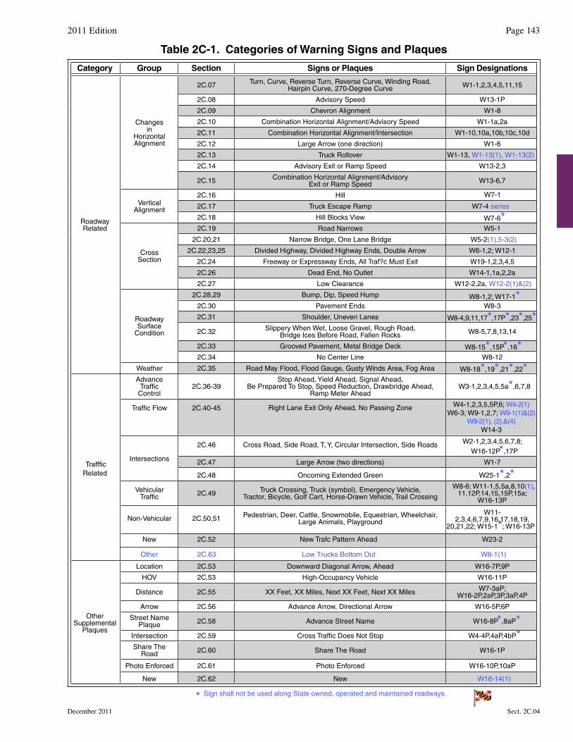
public travel and to situations that might not be readily apparent to road users. Warning signs alert road users to conditions that might call for a reduction of speed or an action in the interest of safety and efficient traffic operations.
Section 2C.02 Application of Warning Signs Standard: 01 The use of warning signs shall be based on an engineering study or on engineering judgment. Guidance:02 The use of warning signs should be kept to a minimum as the unnecessary use of warning signs tends to breed
disrespect for all signs. In situations where the condition or activity is seasonal or temporary, the warning sign should be removed or covered when the condition or activity does not exist.
Option: 03 Consistent with the provisions of Chapter 2L, changeable message signs may be used to display a warning message. 04 Consistent with the provisions of Chapter 4L, a Warning Beacon may be used in combination with a standard
warning sign. Support: 05 The categories of warning signs are shown in Table 2C-1. 06 Warning signs provided in this Manual cover most of the conditions that are likely to be encountered. Additional
warning signs for low-volume roads (as defined in Section 5A.01), temporary traffic control zones, school areas, grade crossings, and bicycle facilities are discussed in Parts 5 through 9, respectively.
07 Section 1A.09 contains information regarding the assistance that is available to jurisdictions that do not have engineers on their staffs who are trained and/or experienced in traffic control devices.
Section 2C.03 Design of Warning Signs Standard:01 Except as provided in Paragraph 2 or unless specifically designated otherwise, all warning signs shall be
diamond-shaped (square with one diagonal vertical) with a black legend and border on a fluorescent yellow background. Warning signs shall be designed in accordance with the sizes, shapes, colors, and legends contained in the “Standard Highway Signs and Markings” book (see Section 1A.11) and the Maryland Standard Sign Book.
Option: 02 A warning sign that is larger than the size shown in the Oversized column in Table 2C-2 for that particular sign may
be diamond-shaped or may be rectangular or square in shape. 03 Except for symbols on warning signs, minor modifications may be made to the design provided that the essential
appearance characteristics are met. Modifications may be made to the symbols shown on combined horizontal alignment/intersection signs (see Section 2C.11) and intersection warning signs (see Section 2C.46) in order to approximate the geometric configuration of the intersecting roadway(s).
04 Word message warning signs other than those provided in this Manual may be developed and installed by State and local highway agencies.
05 Warning signs regarding conditions associated with pedestrians, bicyclists, and playgrounds may have a black legend and border on a fluorescent yellow or fluorescent yellow-green background.
Standard:06 Warning signs regarding conditions associated with school buses and schools and their related supplemental
plaques shall have a black legend and border on a fluorescent yellow-green background (see Section 7B.07).
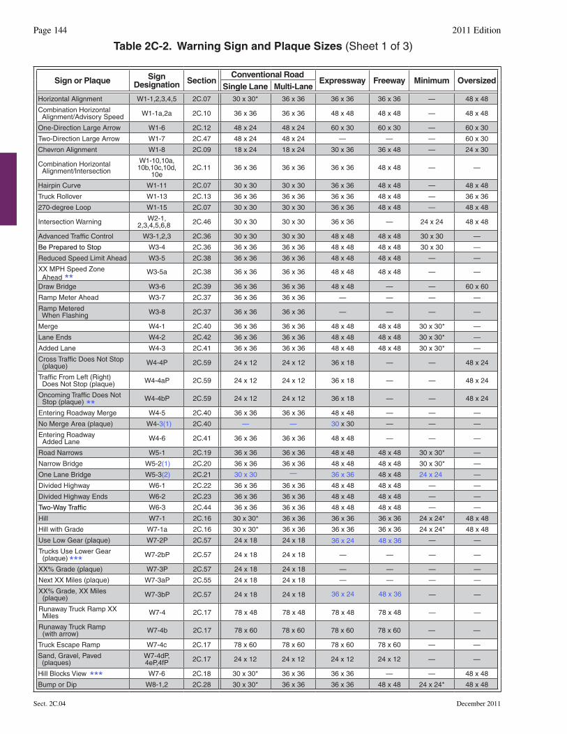
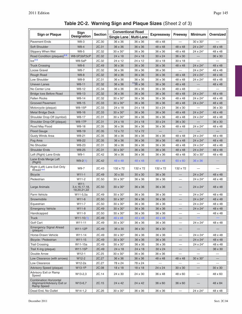
Section 2C.04 Size of Warning Signs Standard:01 Except as provided in Section 2A.11, the sizes for warning signs shall be as shown in Table 2C-2.
Support: 02 Section 2A.11 contains information regarding the applicability of the various columns in Table 2C-2.
2011 Edition Page 143
December 2011 Sect. 2C.04
Table 2C-1. Categories of Warning Signs and Plaques
Category Group Section Signs or Plaques Sign Designations
RoadwayRelated
Changesin
HorizontalAlignment
2C.07 Turn, Curve, Reverse Turn, Reverse Curve, Winding Road,Hairpin Curve, 270-Degree Curve W1-1,2,3,4,5,11,15
2C.08 Advisory Speed W13-1P
2C.09 Chevron Alignment W1-8
2C.10 Combination Horizontal Alignment/Advisory Speed W1-1a,2a
2C.11 Combination Horizontal Alignment/Intersection W1-10,10a,10b,10c,10d
2C.12 Large Arrow (one direction) W1-6
2C.13 Truck Rollover W1-13, W1-13(1), W1-13(2)
2C.14 Advisory Exit or Ramp Speed W13-2,3
2C.15 Combination Horizontal Alignment/AdvisoryExit or Ramp Speed W13-6,7
VerticalAlignment
2C.16 Hill
2C.17 Truck Escape Ramp W7-4 series
W7-1
2C.18 Hill Blocks View W7-6*
CrossSection
2C.19 Road Narrows W5-1
2C.20,21 Narrow Bridge, One Lane Bridge W5-2(1),5-3(2)
2C.22,23,25 Divided Highway, Divided Highway Ends, Double Arrow W6-1,2; W12-1
2C.24 Freeway or Expressway Ends, All Traf?c Must Exit W19-1,2,3,4,5
2C.26 Dead End, No Outlet W14-1,1a,2,2a
2C.27 Low Clearance W12-2,2a, W12-2(1)&(2)
RoadwaySurface
Condition
2C.28,29 Bump, Dip, Speed Hump W8-1,2; W17-1*2C.30 Pavement Ends W8-3
2C.31 Shoulder, Uneven Lanes W8-4,9,11,17*,17P*,23*,25*2C.32 Slippery When Wet, Loose Gravel, Rough Road,
Bridge Ices Before Road, Fallen Rocks W8-5,7,8,13,14
2C.33 Grooved Pavement, Metal Bridge Deck W8-15*,15P*,16*2C.34 No Center Line W8-12
Weather 2C.35 Road May Flood, Flood Gauge, Gusty Winds Area, Fog Area W8-18*,19*,21*,22*
TraffficRelated
AdvanceTraffic
Control2C.36-39
Stop Ahead, Yield Ahead, Signal Ahead, Be Prepared To Stop, Speed Reduction, Drawbridge Ahead,
Ramp Meter AheadW3-1,2,3,4,5,5a*,6,7,8
Traffic Flow 2C.40-45 Right Lane Exit Only Ahead, No Passing Zone W4-1,2,3,5,5P,6; W4-2(1)W6-3; W9-1,2,7; W9-1(1)&(2)
W9-2(1), (2),&(4)W14-3
Intersections
2C.46 Cross Road, Side Road, T, Y, Circular Intersection, Side Roads W2-1,2,3,4,5,6,7,8; W16-12P*,17P
2C.47 Large Arrow (two directions) W1-7
2C.48 Oncoming Extended Green W25-1*,2*Vehicular
Traffic 2C.49 Truck Crossing, Truck (symbol), Emergency Vehicle, Tractor, Bicycle, Golf Cart, Horse-Drawn Vehicle, Trail Crossing
W8-6; W11-1,5,5a,8,10(1),11,12P,14,15,15P,15a;
W16-13P
Non-Vehicular 2C.50,51 Pedestrian, Deer, Cattle, Snowmobile, Equestrian, Wheelchair, Large Animals, Playground
W11-2,3,4,6,7,9,16,17,18,19,
20,21,22; W15-1*; W16-13P
New
Other 2C.63 Low Trucks Bottom Out W8-1(1)
2C.52 New Trafc Pattern Ahead W23-2
OtherSupplemental
Plaques
Location 2C.53 Downward Diagonal Arrow, Ahead W16-7P,9P
HOV 2C.53 High-Occupancy Vehicle W16-11P
Distance 2C.55 XX Feet, XX Miles, Next XX Feet, Next XX Miles W7-3aP; W16-2P,2aP,3P,3aP,4P
Arrow 2C.56 Advance Arrow, Directional Arrow W16-5P,6P
Street NamePlaque 2C.58 Advance Street Name W16-8P*,8aP*
Intersection 2C.59 Cross Traffic Does Not Stop W4-4P,4aP,4bP*Share The
Road 2C.60 Share The Road W16-1P
Photo Enforced 2C.61 Photo Enforced W16-10P,10aP
New 2C.62 New W16-14(1)
Sign shall not be used along State owned, operated and maintained roadways.*
Sign or Plaque Sign Designation Section
Conventional RoadExpressway Freeway Minimum Oversized
Single Lane Multi-LaneHorizontal Alignment W1-1,2,3,4,5 2C.07 30 x 30* 36 x 36 36 x 36 36 x 36 — 48 x 48
Combination Horizontal Alignment/Advisory Speed W1-1a,2a 2C.10 36 x 36 36 x 36 48 x 48 48 x 48 — 48 x 48
One-Direction Large Arrow W1-6 2C.12 48 x 24 48 x 24 60 x 30 60 x 30 — 60 x 30
Two-Direction Large Arrow W1-7 2C.47 48 x 24 48 x 24 — — — 60 x 30
Chevron Alignment W1-8 2C.09 18 x 24 18 x 24 30 x 36 36 x 48 — 24 x 30
Combination Horizontal Alignment/Intersection
W1-10,10a, 10b,10c,10d,
10e2C.11 36 x 36 36 x 36 36 x 36 48 x 48 — —
Hairpin Curve W1-11 2C.07 30 x 30 30 x 30 36 x 36 48 x 48 — 48 x 48
Truck Rollover W1-13 2C.13 36 x 36 36 x 36 36 x 36 48 x 48 — 36 x 36
270-degree Loop W1-15 2C.07 30 x 30 30 x 30 36 x 36 48 x 48 — 48 x 48
Intersection Warning W2-1,2,3,4,5,6,8 2C.46 30 x 30 30 x 30 36 x 36 — 24 x 24 48 x 48
Advanced Traffic Control W3-1,2,3 2C.36 30 x 30 30 x 30 48 x 48 48 x 48 30 x 30 —
Be Prepared to Stop W3-4 2C.36 36 x 36 36 x 36 48 x 48 48 x 48 30 x 30 —
Reduced Speed Limit Ahead W3-5 2C.38 36 x 36 36 x 36 48 x 48 48 x 48 — —
XX MPH Speed Zone Ahead
W3-5a 2C.38 36 x 36 36 x 36 48 x 48 48 x 48 — —
Draw Bridge W3-6 2C.39 36 x 36 36 x 36 48 x 48 — — 60 x 60
Ramp Meter Ahead W3-7 2C.37 36 x 36 36 x 36 — — — —
Ramp Metered When Flashing W3-8 2C.37 36 x 36 36 x 36 — — — —
Merge W4-1 2C.40 36 x 36 36 x 36 48 x 48 48 x 48 30 x 30* —
Lane Ends W4-2 2C.42 36 x 36 36 x 36 48 x 48 48 x 48 30 x 30* —
Added Lane W4-3 2C.41 36 x 36 36 x 36 48 x 48 48 x 48 30 x 30* —
Cross Traffic Does Not Stop (plaque) W4-4P 2C.59 24 x 12 24 x 12 36 x 18 — — 48 x 24
Traffic From Left (Right) Does Not Stop (plaque) W4-4aP 2C.59 24 x 12 24 x 12 36 x 18 — — 48 x 24
Oncoming Traffic Does Not Stop (plaque) W4-4bP 2C.59 24 x 12 24 x 12 36 x 18 — — 48 x 24
Entering Roadway Merge W4-5 2C.40 36 x 36 36 x 36 48 x 48 — — —
No Merge Area (plaque) W4-3(1) 2C.40 30 x 30 ——
—
— — —
Entering Roadway Added Lane W4-6 2C.41 36 x 36 36 x 36 48 x 48 — — —
Road Narrows W5-1 2C.19 36 x 36 36 x 36 48 x 48 48 x 48 30 x 30* —
Narrow Bridge W5-2(1) 2C.20 36 x 36 36 x 36 48 x 48 48 x 48 30 x 30* —
One Lane Bridge W5-3(2) 2C.21 30 x 30 36 x 36 48 x 48 24 x 24
36 x 24 48 x 36
36 x 24 48 x 36
—
Divided Highway W6-1 2C.22 36 x 36 36 x 36 48 x 48 48 x 48 — —
Divided Highway Ends W6-2 2C.23 36 x 36 36 x 36 48 x 48 48 x 48 — —
Two-Way Traffic W6-3 2C.44 36 x 36 36 x 36 48 x 48 48 x 48 — —
Hill W7-1 2C.16 30 x 30* 36 x 36 36 x 36 36 x 36 24 x 24* 48 x 48
Hill with Grade W7-1a 2C.16 30 x 30* 36 x 36 36 x 36 36 x 36 24 x 24* 48 x 48
Use Low Gear (plaque) W7-2P 2C.57 24 x 18 24 x 18 — —
Trucks Use Lower Gear (plaque) W7-2bP 2C.57 24 x 18 24 x 18 — — — —
XX% Grade (plaque) W7-3P 2C.57 24 x 18 24 x 18 — — — —
Next XX Miles (plaque) W7-3aP 2C.55 24 x 18 24 x 18 — — — —
XX% Grade, XX Miles (plaque) W7-3bP 2C.57 24 x 18 24 x 18 — —
Runaway Truck Ramp XX Miles W7-4 2C.17 78 x 48 78 x 48 78 x 48 78 x 48 — —
Runaway Truck Ramp (with arrow) W7-4b 2C.17 78 x 60 78 x 60 78 x 60 78 x 60 — —
Truck Escape Ramp W7-4c 2C.17 78 x 60 78 x 60 78 x 60 78 x 60 — —
Sand, Gravel, Paved (plaques)
W7-4dP, 4eP,4fP 2C.17 24 x 12 24 x 12 24 x 12 24 x 12 — —
Hill Blocks View W7-6 2C.18 30 x 30* 36 x 36 36 x 36 — — 48 x 48
Bump or Dip W8-1,2 2C.28 30 x 30* 36 x 36 36 x 36 48 x 48 24 x 24* 48 x 48
Table 2C-2. Warning Sign and Plaque Sizes (Sheet 1 of 3)
Page 144 2011 Edition
Sect. 2C.04 December 2011
**
**
***
***
Sign or Plaque Sign Designation Section
Conventional RoadExpressway Freeway Minimum Oversized
Single Lane Multi-LanePavement Ends W8-3 2C.30 36 x 36 36 x 36 48 x 48 — 30 x 30* —
Soft Shoulder W8-4 2C.31 36 x 36 36 x 36 48 x 48 48 x 48 24 x 24* 48 x 48
Slippery When Wet W8-5 2C.32 30 x 30* 36 x 36 36 x 36 48 x 48 24 x 24* 48 x 48
Road Condition (plaques) W8-5P,5bP,5cP 2C.32 24 x 18 24 x 18 30 x 24 36 x 30 — 36 x 30
Ice W8-5aP 2C.32 24 x 12 24 x 12 30 x 18 30 x 18 — —
Truck Crossing W8-6 2C.49 36 x 36 36 x 36 36 x 36 48 x 48 24 x 24* 48 x 48
Loose Gravel W8-7 2C.32 36 x 36 36 x 36 36 x 36 — 24 x 24* 48 x 48
Rough Road W8-8 2C.32 36 x 36 36 x 36 36 x 36 48 x 48 24 x 24* 48 x 48
Low Shoulder W8-9 2C.31 36 x 36 36 x 36 36 x 36 48 x 48 24 x 24* 48 x 48
Uneven Lanes W8-11 2C.32 36 x 36 36 x 36 36 x 36 48 x 48 — 48 x 48
No Center Line W8-12 2C.34 36 x 36 36 x 36 36 x 36 48 x 48 — —
Bridge Ices Before Road W8-13 2C.32 36 x 36 36 x 36 36 x 36 48 x 48 24 x 24* 48 x 48
Fallen Rocks W8-14 2C.32 30 x 30* 36 x 36 36 x 36 48 x 48 24 x 24* 48 x 48
Grooved Pavement W8-15 2C.33 30 x 30* 36 x 36 36 x 36 48 x 48 24 x 24* 48 x 48
Motorcycle (plaque) W8-15P 2C.33 24 x 18 24 x 18 30 x 24 36 x 30 — 36 x 30
Metal Bridge Deck W8-16 2C.33 30 x 30* 36 x 36 36 x 36 48 x 48 24 x 24* 48 x 48
Shoulder Drop Off (symbol) W8-17 2C.31 30 x 30* 36 x 36 36 x 36 48 x 48 24 x 24* 48 x 48
Shoulder Drop-Off (plaque) W8-17P 2C.31 24 x 18 24 x 18 30 x 24 36 x 30 — 36 x 30
Road May Flood W8-18 2C.35 36 x 36 36 x 36 36 x 36 48 x 48 24 x 24* 48 x 48
Flood Gauge W8-19 2C.35 12 x 72 12 x 72 — — — —
Gusty Winds Area W8-21 2C.35 36 x 36 36 x 36 36 x 36 48 x 48 24 x 24* 48 x 48
Fog Area W8-22 2C.35 36 x 36 36 x 36 36 x 36 48 x 48 24 x 24* 48 x 48
No Shoulder W8-23 2C.31 36 x 36 36 x 36 36 x 36 48 x 48 24 x 24* 48 x 48
Shoulder Ends W8-25 2C.31 30 x 30* 36 x 36 36 x 36 48 x 48 24 x 24* 48 x 48
Left (Right) Lane Ends W9-1 2C.42 36 x 36 36 x 36 36 x 36 48 x 48 30 x 30* 48 x 48
Lane Ends Merge Left (Right) W9-2(1) 2C.42 48 x 48 48 x 48 48 x 48 60 x 60 36 x 36
Right (Left) Lane Exit Only Ahead W9-7 2C.43 132 x 72 132 x 72 132 x 72 132 x 72 — —
—
——
Bicycle W11-1 2C.49 30 x 30 30 x 30 36 x 36 — 24 x 24* 48 x 48
Pedestrian W11-2 2C.50 30 x 30* 36 x 36 36 x 36 — 24 x 24* 48 x 48
Large Animals W11-
3,4,16,17,18,19,20,21,22
2C.50 30 x 30* 36 x 36 36 x 36 — 24 x 24* 48 x 48
Farm Vehicle W11-5,5a 2C.49 30 x 30* 36 x 36 36 x 36 — 24 x 24* 48 x 48
Snowmobile W11-6 2C.50 30 x 30* 36 x 36 36 x 36 — 24 x 24* 48 x 48
Equestrian W11-7 2C.50 30 x 30* 36 x 36 36 x 36 — 24 x 24* 48 x 48
Emergency Vehicle W11-8 2C.49 30 x 30* 36 x 36 36 x 36 — 24 x 24* 48 x 48
Handicapped W11-9 2C.50 30 x 30* 36 x 36 36 x 36 — — 48 x 48
Truck W11-10(1) 2C.49 48 x 48 48 x 48 48 x 48 —
Golf Cart W11-11 2C.49 30 x 30* 36 x 36 36 x 36 — 24 x 24* 48 x 48
Emergency Signal Ahead (plaque) W11-12P 2C.49 36 x 30 36 x 30 36 x 30 — — —
Horse-Drawn Vehicle W11-14 2C.49 30 x 30* 36 x 36 36 x 36 — 24 x 24* 48 x 48
Bicycle / Pedestrian W11-15 2C.49 30 x 30* 36 x 36 36 x 36 — 24 x 24* 48 x 48
Trail Crossing W11-15a 2C.49 30 x 30* 36 x 36 36 x 36 — 24 x 24* 48 x 48
Trail X-ing (plaque) W11-15P 2C.49 24 x 18 24 x 18 30 x 24 — — 36 x 30
Double Arrow W12-1 2C.25 30 x 30* 36 x 36 36 x 36 — — —
Low Clearance (with arrows) W12-2 2C.27 36 x 36 36 x 36 48 x 48 48 x 48 30 x 30* —
Low Clearance W12-2a 2C.27 78 x 24 78 x 24 — — — —
Advisory Speed (plaque) W13-1P 2C.08 18 x 18 18 x 18 24 x 24 30 x 30 — 30 x 30
Advisory Exit or Ramp Speed W13-2,3 2C.14 24 x 30 24 x 30 36 x 48 48 x 60 — 48 x 60
Combination Horizontal Alignment/Advisory Exit or Ramp Speed
W13-6,7 2C.15 24 x 42 24 x 42 36 x 60 36 x 60 — 48 x 84
Dead End, No Outlet W14-1,2 2C.26 30 x 30* 36 x 36 36 x 36 — 24 x 24* 48 x 48
Table 2C-2. Warning Sign and Plaque Sizes (Sheet 2 of 3)
2011 Edition Page 145
December 2011 Sect. 2C.04
***
****
**
Sign or Plaque Sign Designation Section
Conventional RoadExpressway Freeway Minimum Oversized
Single Lane Multi-LaneDead End, No Outlet (with arrow) W14-1a,2a 2C.26 36 x 8 36 x 8 — — — —
No Passing Zone (pennant) W14-3 2C.45 48 x 48 x 36 48 x 48 x 36 — — 40 x 40 x 30 64 x 64 x 48
Playground W15-1 2C.51 30 x 30* 36 x 36 36 x 36 — 24 x 24* 48 x 48
Share the Road (plaque) W16-1P 2C.60 18 x 24 18 x 24 24 x 30 — — 24 x 30
XX Feet W16-2P 2C.55 24 x 18 24 x 18 — — — 30 x 24
XX Ft W16-2aP 2C.55 24 x 12 24 x 12 — — — 30 x 18
XX Miles (2-line plaque) W16-3P 2C.55 30 x 24 30 x 24 — — — —
XX Miles (1-line plaque) W16-3aP 2C.55 30 x 12 30 x 12 — — — —
Next XX Feet (plaque) W16-4P 2C.55 30 x 24 30 x 24 — — — —
Supplemental Arrow (plaque) W16-5P,6P 2C.56 24 x 18 24 x 18 — — — —
Downward Diagonal Arrow (plaque) W16-7P 2C.50 24 x 12 24 x 12 — — — 30 x 18
Advance Street Name (1-line plaque) W16-8P 2C.58 Varies x 8 Varies x 8 — — — —
Advance Street Name (2-line plaque) W16-8aP 2C.58 Varies x 15 Varies x 15 — — — —
Ahead (plaque) W16-9P 2C.50 24 x 12 24 x 12 30 x 18 — — —
Photo Enforced (symbol plaque) W16-10P 2C.61 24 x 12 24 x 12 36 x 18 — — 48 x 24
Photo Enforced (plaque) W16-10aP 2C.61 24 x 18 24 x 18 36 x 30 — — 48 x 36
HOV (plaque) W16-11P 2G.09 24 x 12 24 x 12 30 x 18 — — 30 x 18
Traffic Circle (plaque) W16-12P 2C.46 24 x 18 24 x 18 — — — —
When Flashing (plaque) W16-13P 2C.50 24 x 18 24 x 18 — — — —
New (plaque) W16-14(1) 2C.62 24 x 24 24 x 24 — — — —
Roundabout (plaque) W16-17P 2C.46 24 x 12 24 x 12 — — — —
NOTICE W16-18P 2A.15 24 x 12 24 x 12 — — — —
Speed Hump W17-1 2C.29 30 x 30* 36 x 36 — — 24 x 24* 48 x 48
Freeway Ends XX Miles W19-1 2C.24 — — — 144 x 48 — —
Expressway Ends XX Miles W19-2 2C.24 — — 144 x 48 — — —
Freeway Ends W19-3 2C.24 — — — 48 x 48 — —
Expressway Ends W19-4 2C.24 — — 48 x 48 — — —
All Traffic Must Exit W19-5 2C.24 — — 90 x 48 90 x 48 — —
New Traffic Pattern Ahead W23-2 2C.52 36 x 36 36 x 36 — — — —
Traffic Signal Extended Green W25-1,2 2C.48 24 x 30 24 x 30 — — — —
The minimum size required for diamond-shaped warning signs facing traffic on multi-lane conventional roads shall be 36 x 36 per Section 2C.04
Notes: 1. Larger signs may be used when appropriate2. Dimensions in inches are shown as width x height3. Reference to Standard signs for use along State owned, operated, and maintained roadways can be obtained from the State Highway Administration’s Office of Traffic & Safety, Traffic Engineering Design Division. The Maryland Standard Sign Book is located at: http://www.roads.maryland.gov/Index.aspx?PageId=689
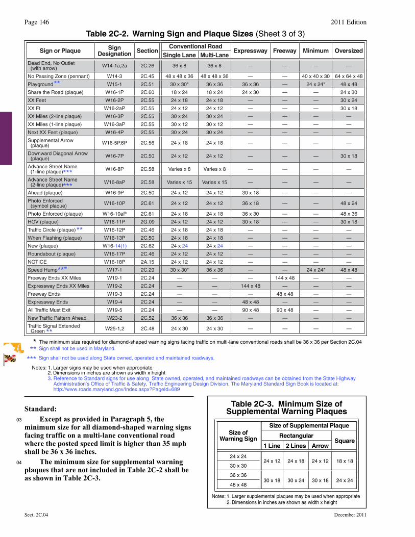
Table 2C-2. Warning Sign and Plaque Sizes (Sheet 3 of 3)
Table 2C-3. Minimum Size of Supplemental Warning Plaques
Size of Warning Sign
Size of Supplemental Plaque
RectangularSquare
1 Line 2 Lines Arrow
24 x 2424 x 12 24 x 18 24 x 12 18 x 18
30 x 30
36 x 3630 x 18 30 x 24 30 x 18 24 x 24
48 x 48
Notes: 1. Larger supplemental plaques may be used when appropriate 2. Dimensions in inches are shown as width x height
Page 146 2011 Edition
Sect. 2C.04 December 2011
Sign shall not be used in Maryland.
Sign shall not be used along State owned, operated and maintained roadways.
***
***
Standard:03 Except as provided in Paragraph 5, the
minimum size for all diamond-shaped warning signs facing traffic on a multi-lane conventional road where the posted speed limit is higher than 35 mph shall be 36 x 36 inches.
04 The minimum size for supplemental warning plaques that are not included in Table 2C-2 shall be as shown in Table 2C-3.
******
**
***
**
**
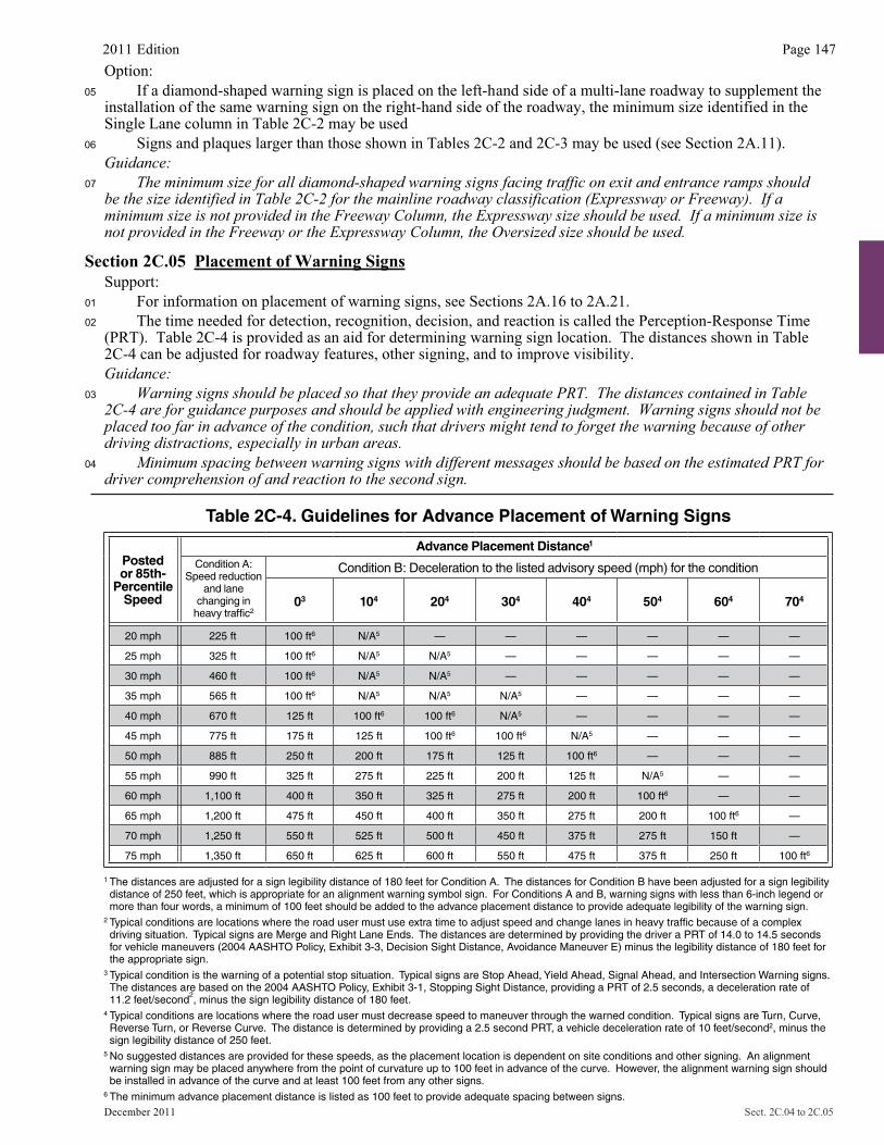
Table 2C-4. Guidelines for Advance Placement of Warning Signs
Postedor 85th-
PercentileSpeed
Advance Placement Distance1
Condition A: Speed reduction
and lane changing in
heavy traffic2
Condition B: Deceleration to the listed advisory speed (mph) for the condition
03 104 204 304 404 504 604 704
20 mph 225 ft 100 ft6 N/A5 — — — — — —
25 mph 325 ft 100 ft6 N/A5 N/A5 — — — — —
30 mph 460 ft 100 ft6 N/A5 N/A5 — — — — —
35 mph 565 ft 100 ft6 N/A5 N/A5 N/A5 — — — —
40 mph 670 ft 125 ft 100 ft6 100 ft6 N/A5 — — — —
45 mph 775 ft 175 ft 125 ft 100 ft6 100 ft6 N/A5 — — —
50 mph 885 ft 250 ft 200 ft 175 ft 125 ft 100 ft6 — — —
55 mph 990 ft 325 ft 275 ft 225 ft 200 ft 125 ft N/A5 — —
60 mph 1,100 ft 400 ft 350 ft 325 ft 275 ft 200 ft 100 ft6 — —
65 mph 1,200 ft 475 ft 450 ft 400 ft 350 ft 275 ft 200 ft 100 ft6 —
70 mph 1,250 ft 550 ft 525 ft 500 ft 450 ft 375 ft 275 ft 150 ft —
75 mph 1,350 ft 650 ft 625 ft 600 ft 550 ft 475 ft 375 ft 250 ft 100 ft6
1 The distances are adjusted for a sign legibility distance of 180 feet for Condition A. The distances for Condition B have been adjusted for a sign legibility distance of 250 feet, which is appropriate for an alignment warning symbol sign. For Conditions A and B, warning signs with less than 6-inch legend or more than four words, a minimum of 100 feet should be added to the advance placement distance to provide adequate legibility of the warning sign.
2 Typical conditions are locations where the road user must use extra time to adjust speed and change lanes in heavy traffic because of a complex driving situation. Typical signs are Merge and Right Lane Ends. The distances are determined by providing the driver a PRT of 14.0 to 14.5 seconds for vehicle maneuvers (2004 AASHTO Policy, Exhibit 3-3, Decision Sight Distance, Avoidance Maneuver E) minus the legibility distance of 180 feet for the appropriate sign.
3 Typical condition is the warning of a potential stop situation. Typical signs are Stop Ahead, Yield Ahead, Signal Ahead, and Intersection Warning signs. The distances are based on the 2004 AASHTO Policy, Exhibit 3-1, Stopping Sight Distance, providing a PRT of 2.5 seconds, a deceleration rate of 11.2 feet/second
2, minus the sign legibility distance of 180 feet.
4 Typical conditions are locations where the road user must decrease speed to maneuver through the warned condition. Typical signs are Turn, Curve, Reverse Turn, or Reverse Curve. The distance is determined by providing a 2.5 second PRT, a vehicle deceleration rate of 10 feet/second2, minus the sign legibility distance of 250 feet.
5 No suggested distances are provided for these speeds, as the placement location is dependent on site conditions and other signing. An alignment warning sign may be placed anywhere from the point of curvature up to 100 feet in advance of the curve. However, the alignment warning sign should be installed in advance of the curve and at least 100 feet from any other signs.
6 The minimum advance placement distance is listed as 100 feet to provide adequate spacing between signs.
2011 Edition Page 147
December 2011 Sect. 2C.04 to 2C.05
Option:05 If a diamond-shaped warning sign is placed on the left-hand side of a multi-lane roadway to supplement the
installation of the same warning sign on the right-hand side of the roadway, the minimum size identified in the Single Lane column in Table 2C-2 may be used
06 Signs and plaques larger than those shown in Tables 2C-2 and 2C-3 may be used (see Section 2A.11). Guidance:
07 The minimum size for all diamond-shaped warning signs facing traffic on exit and entrance ramps should be the size identified in Table 2C-2 for the mainline roadway classification (Expressway or Freeway). If a minimum size is not provided in the Freeway Column, the Expressway size should be used. If a minimum size is not provided in the Freeway or the Expressway Column, the Oversized size should be used.
Section 2C.05 Placement of Warning SignsSupport:
01 For information on placement of warning signs, see Sections 2A.16 to 2A.21. 02 The time needed for detection, recognition, decision, and reaction is called the Perception-Response Time
(PRT). Table 2C-4 is provided as an aid for determining warning sign location. The distances shown in Table 2C-4 can be adjusted for roadway features, other signing, and to improve visibility. Guidance:
03 Warning signs should be placed so that they provide an adequate PRT. The distances contained in Table 2C-4 are for guidance purposes and should be applied with engineering judgment. Warning signs should not be placed too far in advance of the condition, such that drivers might tend to forget the warning because of other driving distractions, especially in urban areas.
04 Minimum spacing between warning signs with different messages should be based on the estimated PRT for driver comprehension of and reaction to the second sign.
Page 148 2011 Edition
Sect. 2C.05 to 2C.07 December 2011
05 The effectiveness of the placement of warning signs should be periodically evaluated under both day and night conditions.Option:
06 Warning signs that advise road users about conditions that are not related to a specific location, such as Deer Crossing or SOFT SHOULDER, may be installed in an appropriate location, based on engineering judgment, since they are not covered in Table 2C-4. Standard:
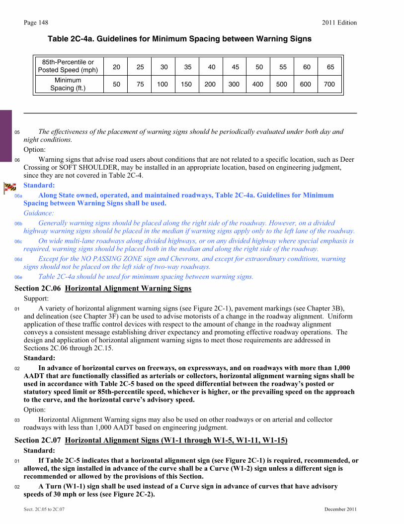
06a Along State owned, operated, and maintained roadways, Table 2C-4a. Guidelines for MinimumSpacing between Warning Signs shall be used.Guidance:
06b Generally warning signs should be placed along the right side of the roadway. However, on a divided highway warning signs should be placed in the median if warning signs apply only to the left lane of the roadway.
06c On wide multi-lane roadways along divided highways, or on any divided highway where special emphasis is required, warning signs should be placed both in the median and along the right side of the roadway.
06d Except for the NO PASSING ZONE sign and Chevrons, and except for extraordinary conditions, warning signs should not be placed on the left side of two-way roadways.
06e Table 2C-4a should be used for minimum spacing between warning signs. Section 2C.06 Horizontal Alignment Warning Signs
Support: 01 A variety of horizontal alignment warning signs (see Figure 2C-1), pavement markings (see Chapter 3B),
and delineation (see Chapter 3F) can be used to advise motorists of a change in the roadway alignment. Uniform application of these traffic control devices with respect to the amount of change in the roadway alignment conveys a consistent message establishing driver expectancy and promoting effective roadway operations. The design and application of horizontal alignment warning signs to meet those requirements are addressed in Sections 2C.06 through 2C.15.
Standard:02 In advance of horizontal curves on freeways, on expressways, and on roadways with more than 1,000
AADT that are functionally classified as arterials or collectors, horizontal alignment warning signs shall be used in accordance with Table 2C-5 based on the speed differential between the roadway’s posted or statutory speed limit or 85th-percentile speed, whichever is higher, or the prevailing speed on the approach to the curve, and the horizontal curve’s advisory speed.
Option: 03 Horizontal Alignment Warning signs may also be used on other roadways or on arterial and collector
roadways with less than 1,000 AADT based on engineering judgment.
Section 2C.07 Horizontal Alignment Signs (W1-1 through W1-5, W1-11, W1-15) Standard:01 If Table 2C-5 indicates that a horizontal alignment sign (see Figure 2C-1) is required, recommended, or
allowed, the sign installed in advance of the curve shall be a Curve (W1-2) sign unless a different sign is recommended or allowed by the provisions of this Section.
02 A Turn (W1-1) sign shall be used instead of a Curve sign in advance of curves that have advisory speeds of 30 mph or less (see Figure 2C-2).
Table 2C-4a. Guidelines for Minimum Spacing between Warning Signs
MinimumSpacing (ft.)
85th-Percentile orPosted Speed (mph) 20 25 30 35 40 45 50 55 60 65
50 75 100 150 200 300 400 500 600 700
2011 Edition Page 149
December 2011 Sect. 2C.07
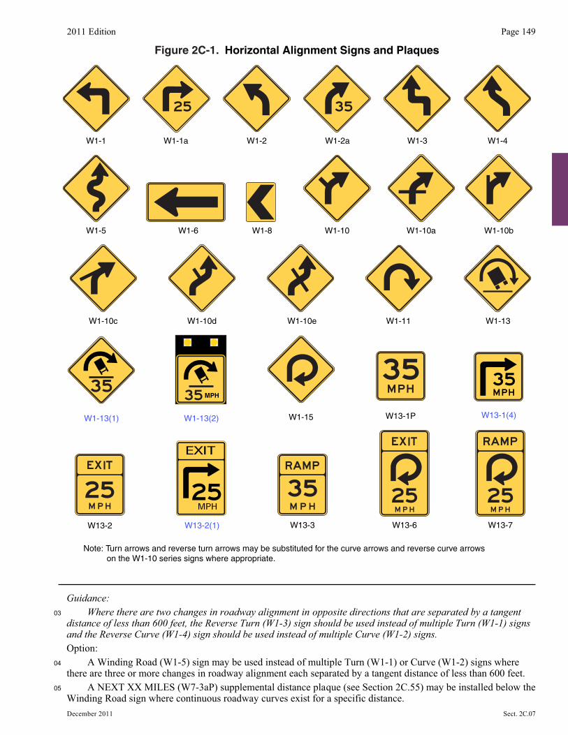
Guidance:03 Where there are two changes in roadway alignment in opposite directions that are separated by a tangent
distance of less than 600 feet, the Reverse Turn (W1-3) sign should be used instead of multiple Turn (W1-1) signs and the Reverse Curve (W1-4) sign should be used instead of multiple Curve (W1-2) signs.
Option: 04 A Winding Road (W1-5) sign may be used instead of multiple Turn (W1-1) or Curve (W1-2) signs where
there are three or more changes in roadway alignment each separated by a tangent distance of less than 600 feet. 05 A NEXT XX MILES (W7-3aP) supplemental distance plaque (see Section 2C.55) may be installed below the
Winding Road sign where continuous roadway curves exist for a specific distance.
Figure 2C-1. Horizontal Alignment Signs and Plaques
W1-2 W1-3 W1-4W1-1 W1-1a W1-2a
W1-15
W13-2 W13-3
W1-5 W1-6 W1-8 W1-10 W1-10bW1-10a
W1-11 W1-13W1-10eW1-10c W1-10d
Note: Turn arrows and reverse turn arrows may be substituted for the curve arrows and reverse curve arrows on the W1-10 series signs where appropriate.
W13-6 W13-7
W1-13(1) W1-13(2)
MPH
W13-1(4)W13-1P
W13-2(1)
Page 150 2011 Edition
Sect. 2C.07 to 2C.08 December 2011
06 If the curve has a change in horizontal alignment of 135 degrees or more, the Hairpin Curve (W1-11) sign may be used instead of a Curve or Turn sign.
07
07a
07b
If the curve has a change of direction of approximately 270 degrees, such as on a cloverleaf interchange ramp, the 270-degree Loop (W1-15) sign may be used instead of a Curve or Turn sign.
The Horizontal Alignment Turn (W1-1a and W1-1a(1)) sign gives notice of an approaching turn with a recommended speed of 30 mph or less, and equal to or less than the prevailing speed.
The Horizontal Alignment Curve (W1-2) sign gives notice of an approaching curve with a recommended speed of greater than 30 mph and equal to or less than the prevailing speed.
Guidance:08 When the Hairpin Curve sign or the 270-degree Loop sign is installed, either a One-Direction Large Arrow
(W1-6) sign or Chevron Alignment (W1-8) signs should be installed on the outside of the turn or curve. If the turn alignment is not readily visible, day and night, a series of two, or preferably three or more,
Chevron Alignment signs should be used on the outside of the turn. If a Large Arrow W1-6 sign used, it should be reserved for extraordinary situations requiring added emphasis.
Section 2C.08 Advisory Speed Plaque (W13-1P) Option: 01 The Advisory Speed (W13-1P) plaque (see Figure 2C-1) may be used to supplement any warning sign to
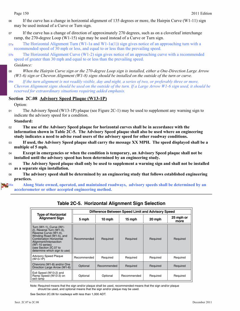
indicate the advisory speed for a condition. Standard:02 The use of the Advisory Speed plaque for horizontal curves shall be in accordance with the
information shown in Table 2C-5. The Advisory Speed plaque shall also be used where an engineering study indicates a need to advise road users of the advisory speed for other roadway conditions.
03 If used, the Advisory Speed plaque shall carry the message XX MPH. The speed displayed shall be a multiple of 5 mph.
04 Except in emergencies or when the condition is temporary, an Advisory Speed plaque shall not be installed until the advisory speed has been determined by an engineering study.
05 The Advisory Speed plaque shall only be used to supplement a warning sign and shall not be installed as a separate sign installation.
06 The advisory speed shall be determined by an engineering study that follows established engineering practices.
Along State owned, operated, and maintained roadways, advisory speeds shall be determined by anaccelerometer or other accepted engineering method.
Table 2C-5. Horizontal Alignment Sign Selection
Type of Horizontal Alignment Sign
Difference Between Speed Limit and Advisory Speed
5 mph 10 mph 15 mph 20 mph 25 mph or more
Turn (W1-1), Curve (W1-2), Reverse Turn (W1-3), Reverse Curve (W1-4), Winding Road (W1-5), and Combination Horizontal Alignment/Intersection(W1-10 series)(see Section 2C.07 to determine which sign to use)
Recommended Required Required Required Required
Advisory Speed Plaque (W13-1P) Recommended Required Required Required Required
Chevrons (W1-8) and/or One Direction Large Arrow (W1-6) Optional Recommended Required Required Required
Exit Speed (W13-2) and Ramp Speed (W13-3) on exit ramp
Optional Optional Recommended Required Required
Note: Required means that the sign and/or plaque shall be used, recommended means that the sign and/or plaque should be used, and optional means that the sign and/or plaque may be used.
See Section 2C.06 for roadways with less than 1,000 ADT.
08a
06a
2011 Edition Page 151
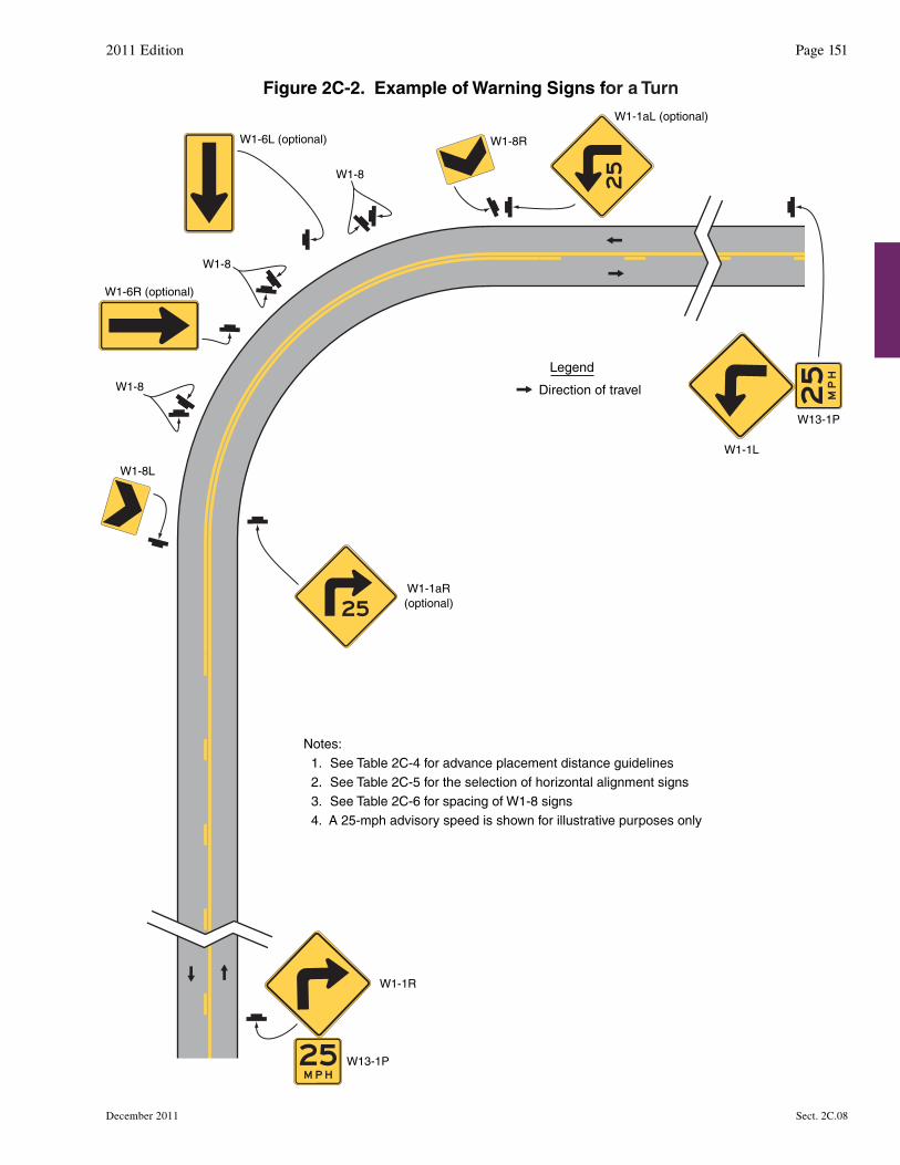
Figure 2C-2. Example of Warning Signs for a Turn
W1-8R
W1-8L
W1-1aR(optional)
W1-1R
W13-1P
W1-6L (optional)
Legend
Direction of travel
W1-8
W1-6R (optional)
W1-8
W1-8
W1-1aL (optional)
W1-1L
W13-1P
Notes:1. See Table 2C-4 for advance placement distance guidelines2. See Table 2C-5 for the selection of horizontal alignment signs3. See Table 2C-6 for spacing of W1-8 signs4. A 25-mph advisory speed is shown for illustrative purposes only
December 2011 Sect. 2C.08
Page 152 2011 Edition
Sect. 2C.08 to 2C.09 December 2011
Support: 07 Among the established engineering practices that are appropriate for the determination of the
recommended advisory speed for a horizontal curve are the following:A. An accelerometer that provides a direct determination of side friction factors B. A design speed equation C. A traditional ball-bank indicator using the following criteria:
1. 16 degrees of ball-bank for speeds of 20 mph or less 2. 14 degrees of ball-bank for speeds of 25 to 30 mph 3. 12 degrees of ball-bank for speeds of 35 mph and higher
08 The 16, 14, and 12 degrees of ball-bank criteria are comparable to the current AASHTO horizontal curve design guidance. Research has shown that drivers often exceed existing posted advisory curve speeds by 7 to 10 mph.
Guidance:09 The advisory speed should be determined based on free-flowing traffic conditions.10 Because changes in conditions, such as roadway geometrics, surface characteristics, or sight distance,
might affect the advisory speed, each location should be evaluated periodically or when conditions change.
Section 2C.09 Chevron Alignment Sign (W1-8) Standard:01 The use of the Chevron Alignment (W1-8) sign (see Figures 2C-1 and 2C-2) to provide additional
emphasis and guidance for a change in horizontal alignment shall be in accordance with the information shown in Table 2C-5.
Option: 02 When used, Chevron Alignment signs may be used instead of or in addition to standard delineators. Standard:03
03a
The Chevron Alignment sign shall be a vertical rectangle. No border shall be used on the Chevron Alignment sign.
A series of at least two Chevron Alignment (W1-8) signs shall be used on the outside of a turn or curve having an Advisory Speed (W13-1P) plaque if the turn or curve alignment is not readily visible,day and night.
04 If used, Chevron Alignment signs shall be installed on the outside of a turn or curve, in line with and at approximately a right angle to approaching traffic. Chevron Alignment signs shall be installed at a minimum height of 4 feet, measured vertically from the bottom of the sign to the elevation of the near edge of the traveled way.
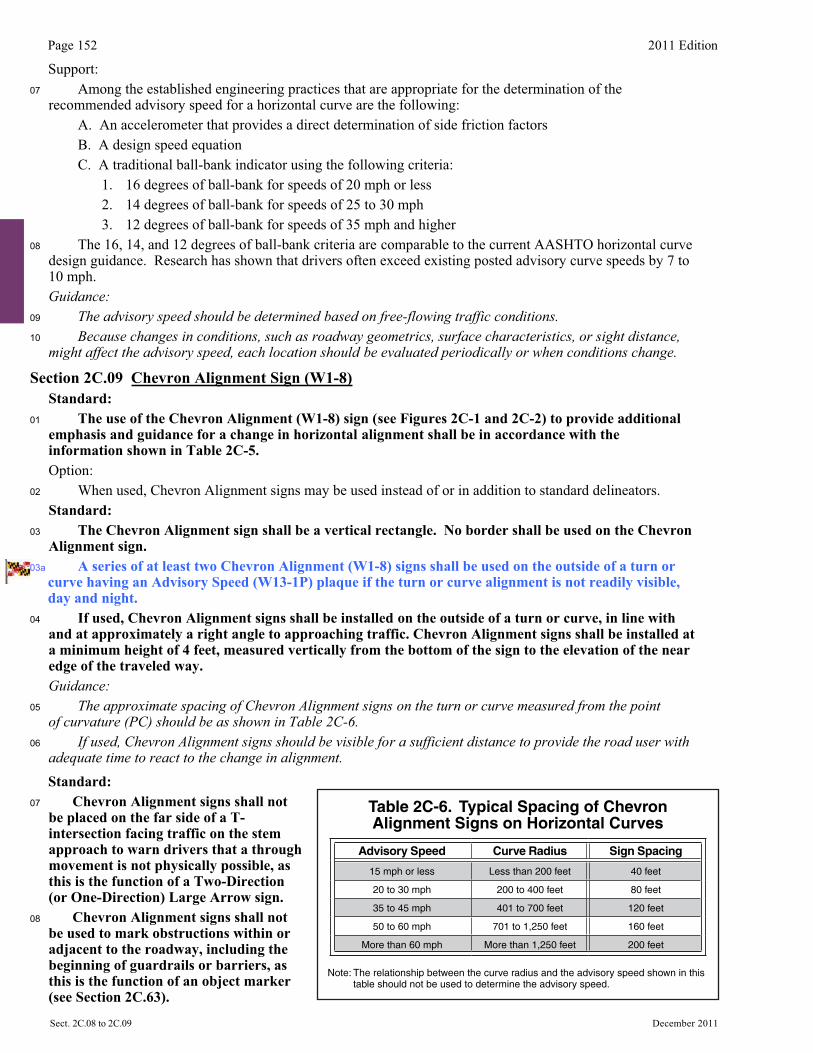
Guidance:05 The approximate spacing of Chevron Alignment signs on the turn or curve measured from the point
of curvature (PC) should be as shown in Table 2C-6.06 If used, Chevron Alignment signs should be visible for a sufficient distance to provide the road user with
adequate time to react to the change in alignment. Standard:
07 Chevron Alignment signs shall not be placed on the far side of a T-intersection facing traffic on the stem approach to warn drivers that a through movement is not physically possible, as this is the function of a Two-Direction (or One-Direction) Large Arrow sign.
08 Chevron Alignment signs shall not be used to mark obstructions within or adjacent to the roadway, including the beginning of guardrails or barriers, as this is the function of an object marker (see Section 2C.63).
Table 2C-6. Typical Spacing of Chevron Alignment Signs on Horizontal Curves
Advisory Speed Curve Radius Sign Spacing
15 mph or less Less than 200 feet 40 feet
20 to 30 mph 200 to 400 feet 80 feet
35 to 45 mph 401 to 700 feet 120 feet
50 to 60 mph 701 to 1,250 feet 160 feet
More than 60 mph More than 1,250 feet 200 feet
Note: The relationship between the curve radius and the advisory speed shown in this table should not be used to determine the advisory speed.
2011 Edition Page 153
December 2011 Sect. 2C.10 to 2C.12�
Section 2C.10 Combination Horizontal Alignment/Advisory Speed Signs (W1-1a, W1-2a) Option: 01 The Turn (W1-1) sign or the Curve (W1-2) sign may be combined with the Advisory Speed (W13-1P)
plaque (see Section 2C.08) to create a combination Turn/Advisory Speed (W1-1a) sign or combination Curve/Advisory Speed (W1-2a) sign (see Figure 2C-1).
02 The combination Horizontal Alignment/Advisory Speed sign may be used to supplement the advance Horizontal Alignment warning sign and Advisory Speed plaque based upon an engineering study.
Standard:03 If used, the combination Horizontal Alignment/Advisory Speed sign shall not be used alone and shall
not be used as a substitute for a Horizontal Alignment warning sign and Advisory Speed plaque at the advance warning location. The combination Horizontal Alignment/Advisory Speed sign shall only be used as a supplement to the advance Horizontal Alignment warning sign If used, the combination Horizontal Alignment/Advisory Speed sign shall be installed at the beginning of the turn or curve.
Guidance:04 The advisory speed displayed on the combination Horizontal Alignment/Advisory Speed sign should be
based on the advisory speed for the horizontal curve using recommended engineering practices (see Section 2C.08).
Section 2C.11 Combination Horizontal Alignment/Intersection Signs (W1-10 Series) Option: 01 The Turn (W1-1) sign or the Curve (W1-2) sign may be combined with the Cross Road (W2-1) sign or the
Side Road (W2-2 or W2-3) sign to create a combination Horizontal Alignment/Intersection (W1-10 series) sign (see Figure 2C-1) that depicts the condition where an intersection occurs within or immediately adjacent to a turn or curve.
Guidance:02 Elements of the combination Horizontal Alignment/Intersection sign related to horizontal alignment
should comply with the provisions of Section 2C.07, and elements related to intersection configuration should comply with the provisions of Section 2C.46. The symbol design should approximate the configuration of the intersecting roadway(s). No more than one Cross Road or two Side Road symbols should be displayed on any one combination Horizontal Alignment/Intersection sign.
Standard:03 The use of the combination Horizontal Alignment/Intersection sign shall be in accordance with the
appropriate Turn or Curve sign information shown in Table 2C-5.
Section 2C.12 One-Direction Large Arrow Sign (W1-6) Option: 01 A One-Direction Large Arrow (W1-6) sign (see Figure 2C-1) may be used either as a supplement or
alternative to Chevron Alignment signs in order to delineate a change in horizontal alignment (see Figure 2C-2). 02 A One-Direction Large Arrow (W1-6) sign may be used to supplement a Turn or Reverse Turn sign (see
Figure 2C-2) to emphasize the abrupt curvature. Standard:03 The One-Direction Large Arrow sign shall be a horizontal rectangle with an arrow pointing to the
left or right.04 The use of the One-Direction Large Arrow sign shall be in accordance with the information shown
in Table 2C-5.05 If used, the One-Direction Large Arrow sign shall be installed on the outside of a turn or curve in
line with and at approximately a right angle to approaching traffic.06 The One-Direction Large Arrow sign shall not be used where there is no alignment change in the
direction of travel, such as at the beginnings and ends of medians or at center piers.07 The One-Direction Large Arrow sign directing traffic to the right shall not be used in the central
island of a roundabout. 07a A One-Direction Large Arrow (W1-6) sign shall be used to complement a Turn sign along roadways
having a prevailing speed of 45 mph or higher.
Page 154 2011 Edition
Sect. 2C.12 to 2C.14 December 2011�
Guidance:08 If used, the One-Direction Large Arrow sign should be visible for a sufficient distance to provide the road
user with adequate time to react to the change in alignment.
Section 2C.13 Truck Rollover Warning Signs (W1-13, W1-13(1), W1-13(2)) Option: 01 A Truck Rollover Warning (W1-13, W1-13(1), W1-13(2)) sign (see Figure 2C-1) may be used to warn
drivers of vehicles with a high center of gravity, such as trucks, tankers, and recreational vehicles, of a curve or turn where geometric conditions might contribute to a loss of control and a rollover as determined by an engineering study. Support:
02 Among the established engineering practices that are appropriate for the determination of the truck rollover potential of a horizontal curve are the following:
A. An accelerometer that provides a direct determination of side friction factors B. A design speed equation C. A traditional ball-bank indicator using 10 degrees of ball-bank
Standard:03 If Truck Rollover Warning (W1-13, W1-13(1), W1-13(2)) signs are used, it shall be accompanied by
an Advisory Speed (W13-1P) plaque indicating the recommended speed for vehicles with a higher center of gravity. Option:
04 The Truck Rollover Warning sign may be displayed as a static sign, as a static sign supplemented by a flashing warning beacon, or as a changeable message sign activated by the detection of an approaching vehicle with a high center of gravity that is traveling in excess of the recommended speed for the condition.
Support: 05 The curved arrow on the Truck Rollover Warning sign shows the direction of roadway curvature. The
truck tips in the opposite direction.
Section 2C.14 Advisory Exit and Ramp Speed Signs (W13-2 and W13-3) Standard:01 Advisory Exit Speed (W13-2) and Advisory Ramp Speed (W13-3) signs (see Figure 2C-1) shall be
vertical rectangles. The use of Advisory Exit Speed and Advisory Ramp Speed signs on freeway and expressway ramps shall be in accordance with the information shown in Table 2C-5.
01a Ramps that exhibit safety issues or have a sharp bend near the gore shall be posted with a diagrammatic Advisory Exit Speed sign that includes both a Turn arrow for advisory speeds of 30 mph or less and the advisory speed, or a Curve arrow for advisory speeds of greater than 30 mph and the advisory speed.
01b When diagrammatic exit speed signs are posted for speeds of 25 mph or less, the related Gore (E5-1 and E5-1a) signs shall be modified to indicate the advisory exit speed. The Gore signs shall have the same curve or turn arrow and the same advisory speed as the diagrammatic advisory exit speed signs.
Guidance:02 If used, the Advisory Exit Speed sign should be installed along the deceleration lane and the advisory
speed displayed should be based on an engineering study. When a Truck Rollover (W1-13) sign (see Section 2C.13) is also installed for the ramp, the advisory exit speed should be based on the truck advisory speed for the horizontal alignment using recommended engineering practices.
03 If used, the Advisory Exit Speed sign should be visible in time for the road user to decelerate and make an exiting maneuver.
03a The following guideline should be used to select the Exit Speed (W13-2) or the Ramp Speed (W13-3) signs: 1. Major roadway to major roadway: W13-3; 2. Major roadway to minor roadway: W13-2; and 3. Minor roadway to major roadway: W13-3.
03b Further warning signs should not be placed for ramps that exhibit no particular safety problems unless there is a sharp curve at a point away from the gore which requires a Turn or Curve warning sign.
03c For ramps experiencing truck accidents, a Tipping Truck sign that includes the advisory exit speed should be used.
2011 Edition Page 155
December 2011 Sect. 2C.14 to 2C.16�
Support: 04 Table 2C-4 lists recommended advance sign placement distances for deceleration to various advisory speeds.
Guidance:05 If used, the Advisory Ramp Speed sign should be installed on the ramp to confirm the ramp advisory speed.06 If used, Chevron Alignment (W1-8) signs and/or One-Direction Large Arrow (W1-6) signs should be
installed on the outside of the exit curve as described in Sections 2C.09 and 2C.12.Option:
07 Where there is a need to remind road users of the recommended advisory speed, a horizontal alignment warning sign with an advisory speed plaque may be installed at or beyond the beginning of the exit curve or on the outside of the curve, provided that it is apparent that the sign applies only to exiting traffic. These signs may also be used at intermediate points along the ramp, especially if the ramp curvature changes and the subsequent curves on the ramp have a different advisory speed than the initial ramp curve.
07a Advisory Exit Speed signs may be placed overhead adjacent to the exit direction sign at locations with restricted sight distances or where short parallel or taper type deceleration lanes are provided.
07b Short ramps that turn immediately into a signalized intersection or to a Stop sign may be posted with a warning sign having the appropriate turn or curve arrow, but with the SIGNAL AHEAD or STOP AHEAD legend in lieu of an advisory exit speed.
07c Delineators, Chevron Alignment (W1-8) signs, and standard Large Arrow (W1-6) signs, also may be used. Support: 08 Figure 2C-3 shows an example of advisory speed signing for an exit ramp.
Section 2C.15 Combination Horizontal Alignment/Advisory Exit and Ramp Speed Signs (W13-6 and W13-7)Option:
01 A horizontal alignment sign (see Section 2C.07) may be combined with an Advisory Exit Speed or Advisory Ramp Speed sign to create a combination Horizontal Alignment/Advisory Exit Speed (W13-6) sign or a combination Horizontal Alignment/Advisory Ramp Speed (W13-7) sign (see Figure 2C-1). These combination signs may be used where the severity of the exit ramp curvature might not be apparent to road users in the deceleration lane or where the curvature needs to be specifically identified as being on the exit ramp rather than on the mainline.
Section 2C.16 Hill Signs (W7-1, W7-1a)Guidance:
01 The Hill (W7-1) sign (see Figure 2C-4) should be used in advance of a downgrade where the length, percent of grade, horizontal curvature, and/or other physical features require special precautions on the part of road users.
02 The Hill sign and supplemental grade (W7-3P) plaque (see Section 2C.57) used in combination, or the W7-1a sign used alone, should be installed in advance of downgrades for the following conditions:
A. 5% grade that is more than 3,000 feet in length, B. 6% grade that is more than 2,000 feet in length, C. 7% grade that is more than 1,000 feet in length, D. 8% grade that is more than 750 feet in length, or E. 9% grade that is more than 500 feet in length.
03 These signs should also be installed for steeper grades or where crash experience and field observations indicate a need.
04 Supplemental plaques (see Section 2C.57) and larger signs should be used for emphasis or where special hill characteristics exist. On longer grades, the use of the Hill sign with a distance (W7-3aP) plaque or the combination distance/grade (W7-3bP) plaque at periodic intervals of approximately 1-mile spacing should be considered.
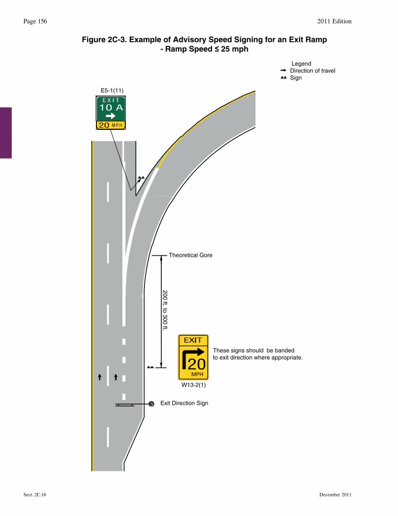
200 ft. to 300 ft.
Theoretical Gore
Exit Direction Sign
W13-2(1)
E5-1(11)
These signs should be bandedto exit direction where appropriate.
LegendDirection of travelSign
Figure 2C-3. Example of Advisory Speed Signing for an Exit Ramp- Ramp Speed ≤ 25 mph
Page 156 2011 Edition
Sect. 2C.16 December 2011
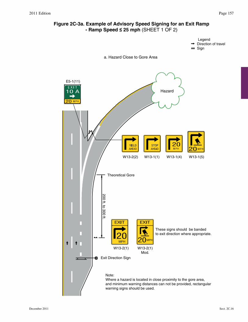
LegendDirection of travelSign
a. Hazard Close to Gore Area
E5-1(11)
These signs should be bandedto exit direction where appropriate.
Note:Where a hazard is located in close proximity to the gore area,and minimum warning distances can not be provided, rectangularwarning signs should be used.
W13-2(1) W13-2(1)Mod.
W13-2(2) W13-1(1) W13-1(4) W13-1(5)
Exit Direction Sign
Theoretical Gore
200 ft. to 300 ft.
Hazard
2011 Edition Page 157
December 2011 Sect. 2C.16
Figure 2C-3a. Example of Advisory Speed Signing for an Exit Ramp- Ramp Speed ≤ 25 mph (SHEET 1 OF 2)
LegendDirection of travelSign
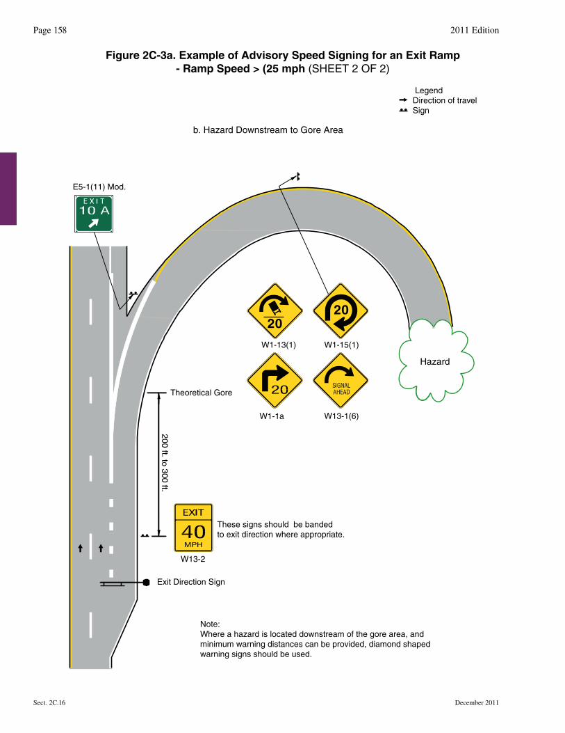
b. Hazard Downstream to Gore Area
Hazard
These signs should be bandedto exit direction where appropriate.
W1-1a
W13-2
E5-1(11) Mod.
W1-13(1)
W13-1(6)
W1-15(1)
Exit Direction Sign
Theoretical Gore
Note:Where a hazard is located downstream of the gore area, and minimum warning distances can be provided, diamond shapedwarning signs should be used.
20
200 ft. to 300 ft.
Figure 2C-3a. Example of Advisory Speed Signing for an Exit Ramp- Ramp Speed > (25 mph (SHEET 2 OF 2)
Page 158 2011 Edition
Sect. 2C.16 December 2011
20
LegendDirection of travelSign
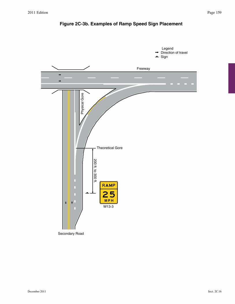
Phy
sica
l Gor
e
Theoretical Gore
W13-3
Secondary Road
Freeway
200 ft. to 300 ft.
Figure 2C-3b. Examples of Ramp Speed Sign Placement
2011 Edition Page 159
December 2011 Sect. 2C.16
M P H
Page 160 2011 Edition
December 2011Sect. 2C.16 to 2C.17
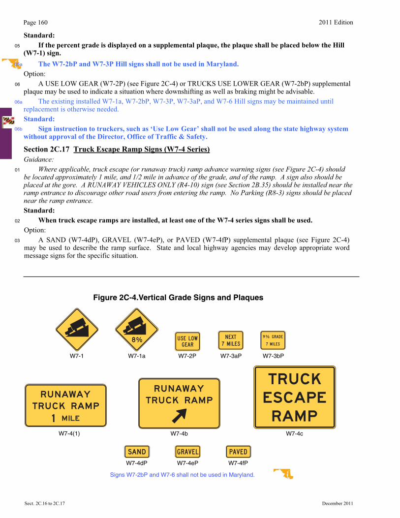
Standard:05 If the percent grade is displayed on a supplemental plaque, the plaque shall be placed below the Hill
(W7-1) sign. The W7-2bP and W7-3P Hill signs shall not be used in Maryland.
Option: 06 A USE LOW GEAR (W7-2P) (see Figure 2C-4) or TRUCKS USE LOWER GEAR (W7-2bP) supplemental
plaque may be used to indicate a situation where downshifting as well as braking might be advisable. The existing installed W7-1a, W7-2bP, W7-3P, W7-3aP, and W7-6 Hill signs may be maintained until
replacement is otherwise needed. Standard:
Sign instruction to truckers, such as ‘Use Low Gear’ shall not be used along the state highway system without approval of the Director, Office of Traffic & Safety.
Section 2C.17 Truck Escape Ramp Signs (W7-4 Series)Guidance:
01 Where applicable, truck escape (or runaway truck) ramp advance warning signs (see Figure 2C-4) should be located approximately 1 mile, and 1/2 mile in advance of the grade, and of the ramp. A sign also should be placed at the gore. A RUNAWAY VEHICLES ONLY (R4-10) sign (see Section 2B.35) should be installed near the ramp entrance to discourage other road users from entering the ramp. No Parking (R8-3) signs should be placed near the ramp entrance. Standard:
02 When truck escape ramps are installed, at least one of the W7-4 series signs shall be used. Option: 03 A SAND (W7-4dP), GRAVEL (W7-4eP), or PAVED (W7-4fP) supplemental plaque (see Figure 2C-4)
may be used to describe the ramp surface. State and local highway agencies may develop appropriate word message signs for the specific situation.
Figure 2C-4.Vertical Grade Signs and Plaques
W7-2PW7-1 W7-1a W7-3aP W7-3bP
W7-4(1) W7-4b W7-4c
W7-4dP W7-4eP W7-4fP
Signs W7-2bP and W7-6 shall not be used in Maryland.
05a
06a
06b
2011 Edition Page 161
December 2011 Sect. 2C.18 to 2C.19
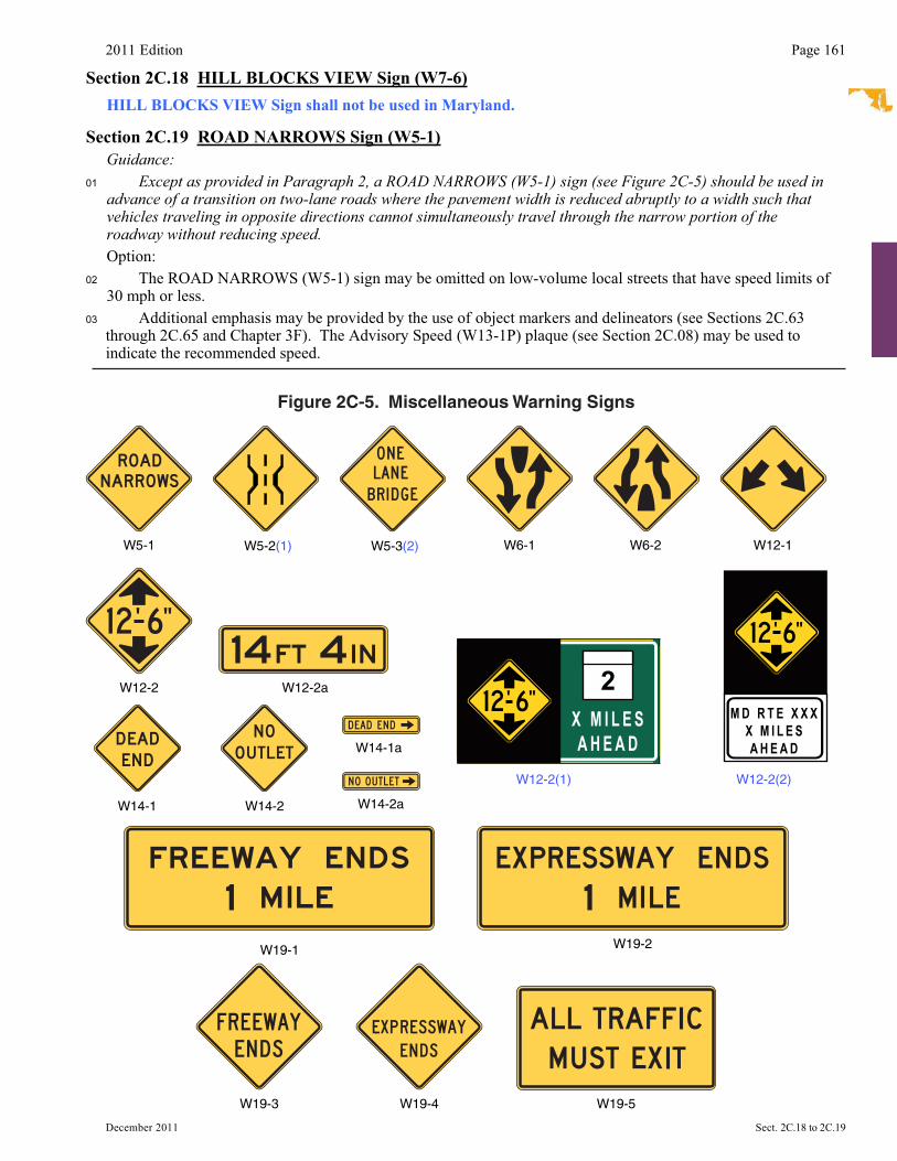
Section 2C.18 HILL BLOCKS VIEW Sign (W7-6) HILL BLOCKS VIEW Sign shall not be used in Maryland..
Section 2C.19 ROAD NARROWS Sign (W5-1) Guidance:01 Except as provided in Paragraph 2, a ROAD NARROWS (W5-1) sign (see Figure 2C-5) should be used in
advance of a transition on two-lane roads where the pavement width is reduced abruptly to a width such that vehicles traveling in opposite directions cannot simultaneously travel through the narrow portion of the roadway without reducing speed.
Option: 02 The ROAD NARROWS (W5-1) sign may be omitted on low-volume local streets that have speed limits of
30 mph or less. 03 Additional emphasis may be provided by the use of object markers and delineators (see Sections 2C.63
through 2C.65 and Chapter 3F). The Advisory Speed (W13-1P) plaque (see Section 2C.08) may be used to indicate the recommended speed.
W6-1W5-1 W6-2 W12-1
Figure 2C-5. Miscellaneous Warning Signs
W12-2
W14-1
W14-1a
W12-2a
W14-2 W14-2a
W19-1 W19-2
W19-3 W19-4 W19-5
W12-2(1)
2X M I L E SA H E A D
W12-2(2)
M D R T E X X XX M I L E SA H E A D
W5-2(1) W5-3(2)
Page 162 2011 Edition
Sect. 2C.20 to 2C.24 December 2011�
Section 2C.20 NARROW BRIDGE Sign (W5-2) Guidance:01 A NARROW BRIDGE (W5-2(1)) sign (see Figure 2C-5) should be used in advance of any bridge or culvert
having a two-way roadway clearance width of 16 to 18 feet, or any bridge or culvert having a roadway clearance less than the width of the approach travel lanes.
02 Additional emphasis should be provided by the use of object markers, delineators, and/or pavement markings.
Option: 03 A NARROW BRIDGE sign may be used in advance of a bridge or culvert on which the approach shoulders
are narrowed or eliminated.
Section 2C.21 ONE LANE BRIDGE Sign (W5-3) Guidance:01 A ONE LANE BRIDGE (W5-3(2)) sign (see Figure 2C-5) should be used on two-way roadways in advance
of any bridge or culvert:A. Having a clear roadway width of less than 16 feet, orB. Having a clear roadway width of less than 18 feet when commercial vehicles constitute a high
proportion of the traffic, orC. Having a clear roadway width of 18 feet or less where the sight distance is limited on the approach to
the structure.02 Additional emphasis should be provided by the use of object markers, delineators, and/or pavement
markings.
Section 2C.22 Divided Highway Sign (W6-1) Guidance:01 A Divided Highway (W6-1) sign (see Figure 2C-5) should be used on the approaches to a section of highway
(not an intersection or junction) where the opposing flows of traffic are separated by a median or other physical barrier.
Standard:02 The Divided Highway (W6-1) sign shall not be used instead of a Keep Right (R4-7 series) sign on
the approach end of a median island.
Section 2C.23 Divided Highway Ends Sign (W6-2) Guidance:01 A Divided Highway Ends (W6-2) sign (see Figure 2C-5) should be used in advance of the end of a section
of physically divided highway (not an intersection or junction) as a warning of two-way traffic ahead.02 The Two-Way Traffic (W6-3) sign (see Section 2C.44) should be used to give warning and notice of the
transition to a two-lane, two-way section. Section 2C.24 Freeway or Expressway Ends Signs (W19 Series) Option: 01 A FREEWAY ENDS XX MILES (W19-1) sign or a FREEWAY ENDS (W19-3) sign (see Figure 2C-5)
may be used in advance of the end of a freeway. 02 An EXPRESSWAY ENDS XX MILES (W19-2) sign or an EXPRESSWAY ENDS (W19-4) sign (see
Figure 2C-5) may be used in advance of the end of an expressway. 03 The rectangular W19-1 and W19-2 signs may be post-mounted or may be mounted overhead
for increased emphasis. Guidance:04 If the reason that the freeway is ending is that the next portion of the freeway is not yet constructed and as a
result all traffic must use an exit ramp to leave the freeway, an ALL TRAFFIC MUST EXIT (W19-5) sign (see Figure 2C-5) should be used in addition to the Freeway Ends signs in advance of the downstream end of the freeway.
2011 Edition Page 163
December 2011 Sect. 2C.25 to 2C.27�
Section 2C.25 Double Arrow Sign (W12-1) Option: 01 The Double Arrow (W12-1) sign (see Figure 2C-5) may be used to advise road users that traffic is
permitted to pass on either side of an island, obstruction, or gore in the roadway. Traffic separated by this sign may either rejoin or change directions.
Guidance:02 If used on an island, the Double Arrow sign should be mounted near the approach end. 03 If used in front of a pier or obstruction, the Double Arrow sign should be mounted on the face of, or just in
front of, the obstruction. Where stripe markings are used on the obstruction, they should be discontinued to leave a 3-inch space around the outside of the sign.
03a Other guide signing or delineation (e.g., the OM-3(2) two-directional object marker) should be used instead when traffic flows split and go to different destinations.
Section 2C.26 DEAD END/NO OUTLET Signs (W14-1, W14-1a, W14-2, W14-2a) Option: 01 The DEAD END (W14-1) sign (see Figure 2C-5) may be used at the entrance of a single road or street that
terminates in a dead end or cul-de-sac. The NO OUTLET (W14-2) sign (see Figure 2C-5) may be used at the entrance to a road or road network from which there is no other exit.
02 DEAD END (W14-1a) or NO OUTLET (W14-2a) signs (see Figure 2C-5) may be used in combination with Street Name (D3-1) signs (see Section 2D.43) to warn turning traffic that the cross street ends in the direction indicated by the arrow.
03 At locations where the cross street does not have a name, the W14-1a or W14-2a signs may be used alone in place of a street name sign.
Standard:04 The DEAD END (W14-1a) and NO OUTLET (W14-2a) signs shall be horizontal rectangles with
an arrow pointing to the left or right.05 When the W14-1 or W14-2 sign is used, the sign shall be posted as near as practical to the entry
point or at a sufficient advance distance to permit the road user to avoid the dead end or no outlet condition by turning at the nearest intersecting street.
06 The DEAD END (W14-1a) or NO OUTLET (W14-2a) signs shall not be used instead of the W14-1 or W14-2 signs where traffic can proceed straight through the intersection into the dead end street or no outlet area.
Section 2C.27 Low Clearance Signs (W12-2, W12-2(1), W12-2(2) and W12-2a) Standard:01 The Low Clearance (W12-2, W12-2(1), W12-2(2)) signs (see Figure 2C-5) shall be used to warn
road users of clearances less than 12 inches above the statutory maximum vehicle height. Guidance:02 The actual clearance should be displayed on the Low Clearance sign to the nearest 1 inch not exceeding
the actual clearance. However, in areas that experience changes in temperature causing frost action, a reduction, not exceeding 3 inches, should be used for this condition.
03 Where the clearance is less than the legal maximum vehicle height, the W12-2 sign with a supplemental distance plaque should be placed at the nearest intersecting road or wide point in the road at which a vehicle can detour or turn around.
04 In the case of an arch or other structure under which the clearance varies greatly, two or more signs should be used as necessary on the structure itself to give information as to the clearances over the entire roadway.
05 Clearances should be evaluated periodically, particularly when resurfacing operations have occurred. Option:�06 The Low Clearance sign may be installed on or in advance of the structure. If a sign is placed on the
structure, it may be a rectangular shape (W12-2a) with the appropriate legend (see Figure 2C-5).
Page 164 2011 Edition
Sect. 2C.28 to 2C.31 December 2011�
Section 2C.28 BUMP and DIP Signs (W8-1, W8-2) Guidance:01 BUMP (W8-1) and DIP (W8-2) signs (see Figure 2C-6) should be used to give warning of a sharp rise
or depression in the profile of the road. Option: 02 These signs may be supplemented with an Advisory Speed plaque (see Section 2C.08).Standard:03 The DIP sign shall not be used at a short stretch of depressed alignment that might momentarily
hide a vehicle. Guidance:04 A short stretch of depressed alignment that might momentarily hide a vehicle should be treated as a no-
passing zone when center line striping is provided on a two-lane or three-lane road (see Section 3B.02).
Section 2C.29 SPEED HUMP Sign (W17-1) Guidance:01 The SPEED HUMP (W17-1) sign (see Figure 2C-6) should be used to give warning of a vertical deflection in
the roadway that is designed to limit the speed of traffic.02 If used, the SPEED HUMP sign should be supplemented by an Advisory Speed plaque (see Section 2C.08). Option: 03 If a series of speed humps exists in close proximity, an Advisory Speed plaque may be eliminated on all but
the first SPEED HUMP sign in the series. 04 The legend SPEED BUMP may be used instead of the legend SPEED HUMP on the W17-1 sign. Support: 05 Speed humps generally provide more gradual vertical deflection than speed bumps. Speed bumps limit the
speed of traffic more severely than speed humps. Other forms of speed humps include speed tables and raised intersections. However, these differences in engineering terminology are not well known by the public, so for signing purposes these terms are interchangeable.
Section 2C.30 PAVEMENT ENDS Sign (W8-3) Guidance:01 A PAVEMENT ENDS (W8-3) word message sign (see Figure 2C-6) should be used where a paved surface
changes to either a gravel treated surface or an earth road surface. Option: 02 An Advisory Speed plaque (see Section 2C.08) may be used when the change in roadway condition requires a
reduced speed.
Section 2C.31 Shoulder Signs (W8-4, W8-9, W8-17, W8-23, and W8-25) Option: 01 The SOFT SHOULDER (W8-4) sign (see Figure 2C-6) may be used to warn of a soft shoulder condition. 02 The LOW SHOULDER (W8-9) sign (see Figure 2C-6) may be used to warn of a shoulder condition where
there is an elevation difference of less than 3 inches between the shoulder and the travel lane. Guidance:03 The Shoulder Drop Off (W8-17) sign (see Figure 2C-6) should be used where an unprotected shoulder drop-
off, adjacent to the travel lane, exceeds 3 inches in depth for a significant continuous length along the roadway, based on engineering judgment.
Option: 04 A SHOULDER DROP-OFF (W8-17P) supplemental plaque (see Figure 2C-6) may be mounted below the
W8-17 sign. 05 The NO SHOULDER (W8-23) sign (see Figure 2C-6) may be used to warn road users that a shoulder does
not exist along a portion of the roadway. 06 The SHOULDER ENDS (W8-25) sign (see Figure 2C-6) may be used to warn road users that a shoulder is
ending. Standard:07 When used, shoulder signs shall be placed in advance of the condition (see Table 2C-4).
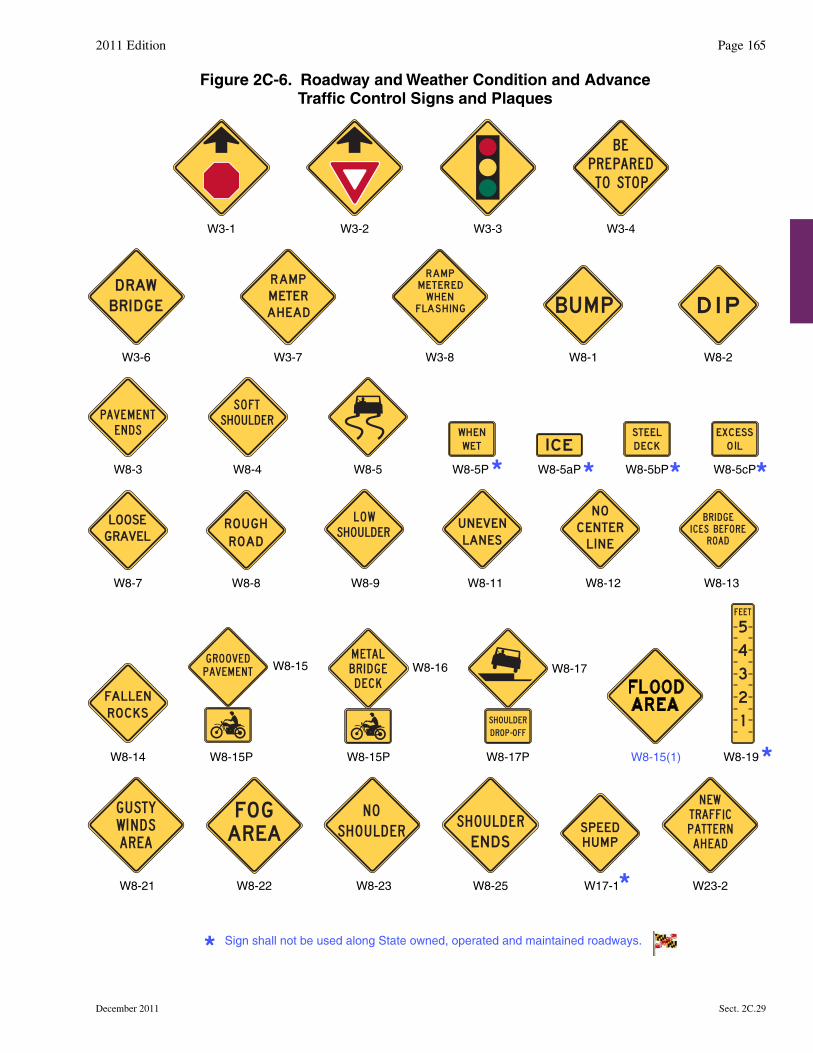
2011 Edition Page 165
Figure 2C-6. Roadway and Weather Condition and AdvanceTraffic Control Signs and Plaques
W8-5
W8-7 W8-8
W8-4
W8-2
W8-3
W8-1
W17-1
W3-1 W3-2 W3-3 W3-4
W8-15(1)
W8-23W8-21
W3-7 W3-8
W8-9 W8-12 W8-13
W8-19W8-15P
W8-15
W8-15P
W8-16
W23-2
W8-11
W8-25W8-22
W8-14
W3-6
W8-5P W8-5cPW8-5bPW8-5aP
W8-17P
W8-17
December 2011 Sect. 2C.29
Sign shall not be used along State owned, operated and maintained roadways.
Page 166 2011 Edition
Sect. 2C.31 to 2C.35 December 2011�
Guidance:08 Additional shoulder signs should be placed at appropriate intervals along the road where the condition
continually exists.
Section 2C.32 Surface Condition Signs (W8-5, W8-7, W8-8, W8-11, W8-13, and W8-14) Option: 01 The Slippery When Wet (W8-5) sign (see Figure 2C-6) may be used to warn of unexpected slippery conditions.
Supplemental plaques with legends such as ICE, WHEN WET, STEEL DECK, or EXCESS OIL may be used with the W8-5 sign to indicate the reason that the slippery conditions might be present.
02 The LOOSE GRAVEL (W8-7) sign (see Figure 2C-6) may be used to warn of loose gravel on the roadway surface.
03 The ROUGH ROAD (W8-8) sign (see Figure 2C-6) may be used to warn of a rough roadway surface. 04 An UNEVEN LANES (W8-11) sign (see Figure 2C-6) may be used to warn of a difference in elevation
between travel lanes.05 The BRIDGE ICES BEFORE ROAD (W8-13) sign (see Figure 2C-6) may be used in advance of bridges to
advise bridge users of winter weather conditions. The BRIDGE ICES BEFORE ROAD sign may be removed or covered during seasons of the year when its message is not relevant.
06 The FALLEN ROCKS (W8-14) sign (see Figure 2C-6) may be used in advance of an area that is adjacent to a hillside, mountain, or cliff where rocks frequently fall onto the roadway.
Guidance:07 When used, Surface Condition signs should be placed in advance of the beginning of the affected section (see
Table 2C-4), and additional signs should be placed at appropriate intervals along the road where the condition exists.
Section 2C.33 Warning Signs and Plaques for Motorcyclists (W8-15, W8-15P, and W8-16) Support: 01 The signs and plaques described in this Section are intended to give motorcyclists advance notice of surface
conditions that might adversely affect their ability to maintain control of their motorcycle under wet or dry conditions. The use of some of the advance surface condition warning signs described in Section 2C.32, such as Slippery When Wet, LOOSE GRAVEL, or ROUGH ROAD, can also be helpful to motorcyclists if those conditions exist.Option:
02 If a portion of a street or highway features a roadway pavement surface that is grooved or textured instead of smooth, such as a grooved skid resistance treatment for a horizontal curve or a brick pavement surface, a GROOVED PAVEMENT (W8-15) sign (see Figure 2C-6) may be used to provide advance warning of this condition to motorcyclists, bicyclists, and other road users. Alternate legends such as TEXTURED PAVEMENT or BRICK PAVEMENT may also be used on the W8-15 sign.
03 If a bridge or a portion of a bridge includes a metal or grated surface, a METAL BRIDGE DECK (W8-16) sign (see Figure 2C-6) may be used to provide advance warning of this condition to motorcyclists, bicyclists, and other road users.
04 A Motorcycle (W8-15P) plaque (see Figure 2C-6) may be mounted below or above a W8-15 or W8-16 sign if the warning is intended to be directed primarily to motorcyclists.
Section 2C.34 NO CENTER LINE Sign (W8-12)Option:
01 The NO CENTER LINE (W8-12) sign (see Figure 2C-6) may be used to warn of a roadway without center line pavement markings.
Section 2C.35 Weather Condition Signs (W8-18, W8-19, W8-21, and W8-22)Option:
01 The ROAD MAY FLOOD (W8-18) sign may be used to warn road users that a section of roadway is subject to frequent flooding. A Depth Gauge (W8-19) sign (see Figure 2C-6) may also be installed within a roadway section that frequently floods.
Standard:02 If used, the Depth Gauge sign shall be in addition to the ROAD MAY FLOOD sign and shall indicate
the depth of the water at the deepest point on the roadway.
2011 Edition Page 167
December 2011 Sect. 2C.35 to 2C.36�
Option: 03 The GUSTY WINDS AREA (W8-21) sign (see Figure 2C-6) may be used to warn road users that wind
gusts frequently occur along a section of highway that are strong enough to impact the stability of trucks, recreational vehicles, and other vehicles with high centers of gravity. A NEXT XX MILES (W7-3a) supplemental plaque may be mounted below the W8-21 sign to inform road users of the length of roadway that frequently experiences strong wind gusts.
04 The FOG AREA (W8-22) sign (see Figure 2C-6) may be used to warn road users that foggy conditions frequently reduce visibility along a section of highway. A NEXT XX MILES (W7-3a) supplemental plaque may be mounted below the W8-22 sign to inform road users of the length of roadway that frequently experiences foggy conditions.
Section 2C.36 Advance Traffic Control Signs (W3-1, W3-2, W3-3, W3-4) Standard:01 The Advance Traffic Control symbol signs (see Figure 2C-6) include the Stop Ahead (W3-1), Yield
Ahead (W3-2), and Signal Ahead (W3-3) signs. These signs shall be installed on an approach to a primary traffic control device that is not visible for a sufficient distance to permit the road user to respond to the device (see Table 2C-4). The visibility criteria for a traffic control signal shall be based on having a continuous view of at least two signal faces for the distance specified in Table 4D-2.
Support: 02 Figure 2A-4 shows the typical placement of an Advance Traffic Control sign. 03 Permanent obstructions causing the limited visibility might include roadway alignment or structures.
Intermittent obstructions might include foliage or parked vehicles. Guidance:04 Where intermittent obstructions occur, engineering judgment should determine the treatment to be
implemented. Option: 05 An Advance Traffic Control sign may be used for additional emphasis of the primary traffic control device,
even when the visibility distance to the device is satisfactory. 06 An advance street name plaque (see Section 2C.58) may be installed above or below an Advance Traffic
Control sign. 07 A warning beacon may be used with an Advance Traffic Control sign. 08 A BE PREPARED TO STOP (W3-4) sign (see Figure 2C-6) may be used to warn of stopped traffic caused
by a traffic control signal or in advance of a section of roadway that regularly experiences traffic congestion. Standard:
08a When electrically controlled RED Signal Ahead warning signs are installed, the normal static Signal�Ahead symbol (W3-3) sign shall also be installed as a backup in the event of power failure.
08b The W3-3 (NEW) sign assembly combines a standard W3-3 with both a "NEW" plate and two flags.�Along the state highway system, it shall be the responsibility of the district sign maintenance team to remove these�assemblies. Guidance:
08c Signal Ahead warning signs (W3-3) should be placed only in advance of signals where the approach�roadway's horizontal or vertical curvature, or other sight distance limiting conditions, prevent drivers from�having a continuous view of at least two (2) signal indications for the distance set forth in Table 4D-1. At�otherlocations an Advance Street Name sign is more appropriate per Section 2D.38.
08d W3-3 signs should be used both on primary and secondary street approaches, as required. Placement�oneach approach should be governed by Table 2C-4.
08e The Signal Ahead sign should include a D3 Series Street Name sign, color black on yellow. 08f W3-3 (NEW) assemblies should be placed in accordance with Table 2C-4 Condition A or B, as the
complexity�of the situation dictates. 08g The W3-3 (NEW) sign assembly should be installed on the main street approach at each new signal�
installation at the time the signal is first turned on and such signs should remain in place for not less than 90 days�nor more than 120 days.
.
Figure 2C-7. Reduced Speed Limit Ahead Signs
W3-5aW3-5
Sign shall not be used along State owned, operated and maintained roadways.
Page 168 2011 Edition
Sect. 2C.36 to 2C.38 December 2011
Option: 08h If the Signal Ahead symbol (W3-3) sign is used as a backup of the electrically controlled RED Signal
Ahead warning signs in the event of power failure, it may be placed on the mast arm support column, or on a nearby ground mounted support.
08i For added emphasis, Portable Changeable Message Signs (PCMS) may be used. Guidance:
08j Portable Changeable Message Signs should be used when the prevailing speed is 50 mph or more. Standard:
08k Only the Signal Ahead symbol (W3-3) signs shall be used in new and replacement installations. Option: 08l Existing SIGNAL AHEAD legend (W3-3(1)) signs may continue to be used until replacement is necessary. Standard:09 When a BE PREPARED TO STOP sign is used in advance of a traffic control signal, it shall be used
in addition to a Signal Ahead sign and shall be placed downstream from the Signal Ahead (W3-3) sign. Option:
10 The BE PREPARED TO STOP sign may be supplemented with a warning beacon (see Section 4L.03). Guidance:
11 When the warning beacon is interconnected with a traffic control signal or queue detection system, the BE PREPARED TO STOP sign should be supplemented with a WHEN FLASHING (W16-13P) plaque (see Figure 2C-12).Support:
12 Section 2C.40 contains information regarding the use of a NO MERGE AREA (W4-5P) supplemental plaque in conjunction with a Yield Ahead sign.
Section 2C.37 Advance Ramp Control Signal Signs (W3-7 and W3-8)Option:
01 A RAMP METER AHEAD (W3-7) sign (see Figure 2C-6) may be used to warn road users that a freeway entrance ramp is metered and that they will encounter a ramp control signal (see Chapter 4I). Guidance:
02 When the ramp control signals are operated only during certain periods of the day, a RAMP METERED WHEN FLASHING (W3-8) sign (see Figure 2C-6) should be installed in advance of the ramp control signal near the entrance to the ramp, or on the arterial on the approach to the ramp, to alert road users to the presence and operation of ramp meters.Standard:
03 The RAMP METERED WHEN FLASHING sign shall be supplemented with a warning beacon (see Section 4L.03) that flashes when the ramp control signal is in operation.
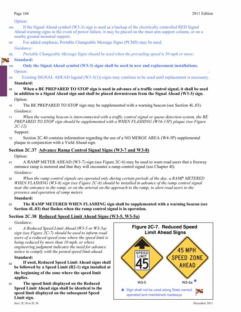
Section 2C.38 Reduced Speed Limit Ahead Signs (W3-5, W3-5a) Guidance: 01 A Reduced Speed Limit Ahead (W3-5 or W3-5a)
sign (see Figure 2C-7) should be used to inform road users of a reduced speed zone where the speed limit is being reduced by more than 10 mph, or where engineering judgment indicates the need for advance notice to comply with the posted speed limit ahead.
Standard: 02 If used, Reduced Speed Limit Ahead signs shall
be followed by a Speed Limit (R2-1) sign installed at the beginning of the zone where the speed limit applies.
03 The speed limit displayed on the Reduced Speed Limit Ahead sign shall be identical to the speed limit displayed on the subsequent Speed Limit sign.
2011 Edition Page 169
December 2011 Sect. 2C.38 to 2C.40
Guidance:If used, the Speed Reduction sign should not be placed within 1,300 feet prior to signalized intersections
for lower speed roadways (35 mph and less) or within 2,000 feet for higher speed roadways (40 mph and higher). See Section 2B.13.
Section 2C.39 DRAW BRIDGE Sign (W3-6)Standard:
01
01a
A DRAW BRIDGE (W3-6) sign (see Figure 2C-6) shall be used in advance of movable bridge signals and gates (see Section 4J.02) to give warning to road users, except in urban conditions where such signing would not be practical.
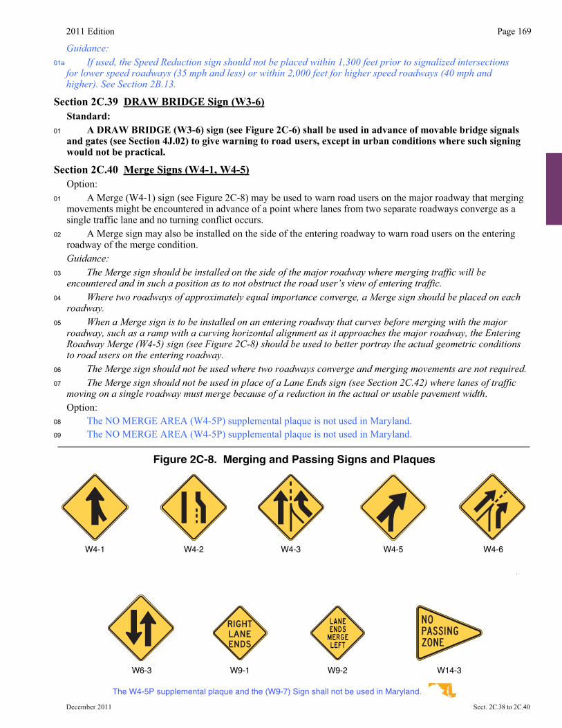
Section 2C.40 Merge Signs (W4-1, W4-5) Option: 01 A Merge (W4-1) sign (see Figure 2C-8) may be used to warn road users on the major roadway that merging
movements might be encountered in advance of a point where lanes from two separate roadways converge as a single traffic lane and no turning conflict occurs.
02 A Merge sign may also be installed on the side of the entering roadway to warn road users on the entering roadway of the merge condition.
Guidance:03 The Merge sign should be installed on the side of the major roadway where merging traffic will be
encountered and in such a position as to not obstruct the road user’s view of entering traffic.04 Where two roadways of approximately equal importance converge, a Merge sign should be placed on each
roadway.05 When a Merge sign is to be installed on an entering roadway that curves before merging with the major
roadway, such as a ramp with a curving horizontal alignment as it approaches the major roadway, the Entering Roadway Merge (W4-5) sign (see Figure 2C-8) should be used to better portray the actual geometric conditions to road users on the entering roadway.
06 The Merge sign should not be used where two roadways converge and merging movements are not required.07 The Merge sign should not be used in place of a Lane Ends sign (see Section 2C.42) where lanes of traffic
moving on a single roadway must merge because of a reduction in the actual or usable pavement width. Option: 08 The NO MERGE AREA (W4-5P) supplemental plaque is not used in Maryland.09 The NO MERGE AREA (W4-5P) supplemental plaque is not used in Maryland.
Figure 2C-8. Merging and Passing Signs and Plaques
W6-3 W9-1 W9-2 W14-3
W4-6W4-1 W4-3 W4-5W4-2
The W4-5P supplemental plaque and the (W9-7) Sign shall not be used in Maryland.
Page 170 2011 Edition
Sect. 2C.36 to 2C.38 December 2011�
Standard:09a If Merge signs are installed along both merging roadways they shall be identical, not mirror image
designs, and shall be installed on the side of each roadway from which merging traffic is to be encountered. Guidance:
09b When possible, one Merge Sign should be installed so as to be visible for both merging roadways.
Section 2C.41 Added Lane Signs (W4-3, W4-6) Guidance:01 The Added Lane (W4-3) sign (see Figure 2C-8) should be installed in advance of a point where two
roadways converge and merging movements are not required. When possible, the Added Lane sign should be placed such that it is visible from both roadways; if this is not possible, an Added Lane sign should be placed on the side of each roadway.
02 When an Added Lane sign is to be installed on a roadway that curves before converging with another roadway that has a tangent alignment at the point of convergence, the Entering Roadway Added Lane (W4-6) sign (see Figure 2C-8) should be used to better portray the actual geometric conditions to road users on the curving roadway.
Section 2C.42 Lane Ends Signs (W4-2, W9-1, W9-2) Guidance:01 The LANE ENDS MERGE LEFT (RIGHT) (W9-2) sign or the Lane Ends (W4-2) sign should be used to warn
of the reduction in the number of traffic lanes in the direction of travel on a multi-lane highway (see Figure 2C-8). Option: 02 The RIGHT (LEFT) LANE ENDS (W9-1) sign (see Figure 2C-8) may be used in advance of the Lane Ends
(W4-2) sign or the LANE ENDS MERGE LEFT (RIGHT) (W9-2) sign as additional warning or to emphasize that the traffic lane is ending and that a merging maneuver will be required. Guidance:
03 If used, the RIGHT (LEFT) LANE ENDS (W9-1) sign should be installed adjacent to the Lane-Reduction Arrow pavement markings.
Option: 04 On one-way streets or on divided highways where the width of the median will permit, two Lane Ends signs
may be placed facing approaching traffic, one on the right-hand side and the other on the left-hand side or median. Support: 05 Section 3B.09 contains information regarding the use of pavement markings in conjunction with a lane
reduction. Guidance:
06 Where an extra lane has been provided for slower moving traffic (see Section 2B.31), a Lane Ends word sign or a Lane Ends (W4-2) symbol sign should be installed in advance of the downstream end of the extra lane.
07 Lane Ends signs should not be installed in advance of the downstream end of an acceleration lane.Standard:
08 In dropped lane situations, regulatory signs (see Section 2B.20) shall be used to inform road users that a through lane is becoming a mandatory turn lane. The W4-2, W9-1, and W9-2 signs shall not be used in dropped lane situations. Support:
08a A Lane Reduction Transition is a condition where motorists traveling along any multi-lane roadway are�forced to transition into a lesser number of through lanes. This differs from a Lane Drop which is a condition�where motorists traveling in a certain lane along any type of roadway are, through geometric conditions or�specialsigns and pavement marking, forced to exit onto a different roadway or change their direction of travel.
08b For controlled access facilities, the RIGHT (LEFT) LANE ENDS (W9-1(1)) sign replaces the W9-1�illustrated in Figure 2C-8, and the layout of the LANE ENDS MERGE LEFT (RIGHT) (W9-2) has been modified,�becoming the W9-2(1). A Lane Ends symbol (W9-2(2)) sign and a companion black and yellow Merge Right�(Left) (W9-2(3)) plate are to be used. The Lane Ends (W9-1(2)) sign is available for overhead installation in place�of the W9-1(1). Standard:
08c The Lane Ends (W9-1(1)) sign shall include the distance between that sign and the beginning of the lane�reduction taper or the legend "BEYOND SIGNAL."
2011 Edition Page 171
December 2011 Sect. 2C.42 to 2C.44�
08d The Lane Ends Merge Left (Right) W9-2(1) sign and the Lane Ends (W4-2) symbol sign shall be�located between signs 1 and 4 according to the warning sign spacing chart for "d" on the Figures 2C-8a and�2C-8b.
08e The Lane Ends (W9-2(2)) Arrow sign shall be placed at the beginning of the lane taper. The W9-2(2)�assembly shall include the Merge Left (Right) W9-2(3) supplemental plate.
08f If used, The Lane Ends Merge Left (Right) W9-2(1) sign shall be placed in advance of the Lane Ends�(W4-2) symbol sign based on the same table. The Lane Ends (W4-2) symbol sign shall be placed in advance�of the lane reduction taper in accordance with Table 2C-4.
08g For other roadways with 85 percentile speeds equal to or greater than 45 mph, the order in�whichsigns appear shall be (see Figure 2C-8a Sheet 1 of 2):
1. W9-1 2. W9-2(1) or W9-2(4) 3. W4-2 4. W9-2(2) and W9-2(3)
08h For roadways with 85 percentile speeds less than 45 MPH, the order in which signs appear shall be (see�Figure 2C-8a Sheet 2 of 2):
1. W9-1 2. W9-2(1) or W9-2(4) 3. W4-2 4. W9-2(2) and W9-2(3)
Option: 08i The Lane Ends-Merge W9-2(4) sign may be used overhead on the signal structure in place of the Lane
Ends Merge Left (Right) W9-2(1) sign. Guidance:08j The ALTERNATE RIGHT OF WAY (W4-2(1)) or W4-2(2)) sign should be considered for use when a lane
reduction transition exists. When the ALTERNATE RIGHT OF WAY (W4-2(1)) or W4-2(2)) sign is used, a FORM SINGLE LANE AHEAD (W4-2(3)) sign should be used.
Support: 08k Additional Guideline regarding the use of ALTERNATE RIGHT OF WAY signs can be obtained from the
Maryland State Highway Administration’s Office of Traffic & Safety, Traffic Engineering Design Division (TEDD) at the address shown on Page i.
Section 2C.43 RIGHT (LEFT) LANE EXIT ONLY AHEAD Sign (W9-7)Option:
01 The RIGHT (LEFT) LANE EXIT ONLY AHEAD (W9-7) sign (see Figure 2C-8) may be used to provide advance warning to road users that traffic in the right-hand (left-hand) lane of a roadway that is approaching a grade-separated interchange will be required to depart the roadway on an exit ramp at the next interchange. Standard:
02 The W9-7 sign shall be a horizontal rectangle with a black legend and border on a yellow background. Guidance: 03 If used, the W9-7 sign should be installed upstream from the first overhead guide sign that contains an
EXIT ONLY sign panel or upstream from the first RIGHT (LEFT) LANE MUST EXIT (R3-33) regulatory sign, whichever is farther upstream from the exit.Support:
04 Section 2B.23 contains information regarding a regulatory sign that can also be used for lane drops at grade-separated interchanges.
Section 2C.44 Two-Way Traffic Sign (W6-3) Guidance:01 A Two-Way Traffic (W6-3) sign (see Figure 2C-8) should be used to warn road users of a transition from a
multi-lane divided section of roadway to a two-lane, two-way section of roadway.02 A Two-Way Traffic (W6-3) sign with an AHEAD (W16-9P) plaque (see Figure 2C-12) should be used to
warn road users of a transition from a one-way street to a two-lane, two-way section of roadway (see Figure 2B-14).
Option: 03 The Two-Way Traffic sign may be used at intervals along a two-lane, two-way roadway and may be used to
supplement the Divided Highway (Road) Ends (W6-2) sign discussed in Section 2C.23.
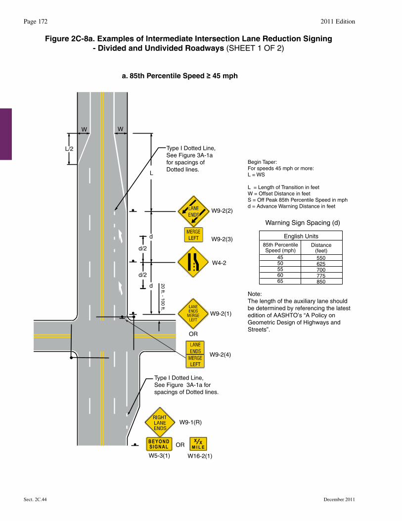
W9-2(1)
W9-2(4)
OR
OR
Type I Dotted Line, See Figure 3A-1a for spacings of Dotted lines.
a. 85th Percentile Speed ≥ 45 mph
Note:The length of the auxiliary lane should be determined by referencing the latest edition of AASHTO’s “A Policy on Geometric Design of Highways and Streets”.
W W
L/2
L
d
d
20 ft. - 100 ft.
W4-2
W9-1(R)
W5-3(1) W16-2(1)
W9-2(2)
W9-2(3)
Warning Sign Spacing (d)
Begin Taper: For speeds 45 mph or more:L = WS
L = Length of Transition in feetW = Offset Distance in feetS = Off Peak 85th Percentile Speed in mphd = Advance Warning Distance in feet
d/2
d/2
Type I Dotted Line, See Figure 3A-1a for spacings of Dotted lines.
BEYONDSIGNAL M I L E
X X
85th PercentileSpeed (mph)
Distance(feet)
English Units
550625700775850
4550556065
Figure 2C-8a. Examples of Intermediate Intersection Lane Reduction Signing- Divided and Undivided Roadways (SHEET 1 OF 2)
2011 EditionPage 172
December 2011Sect. 2C.44
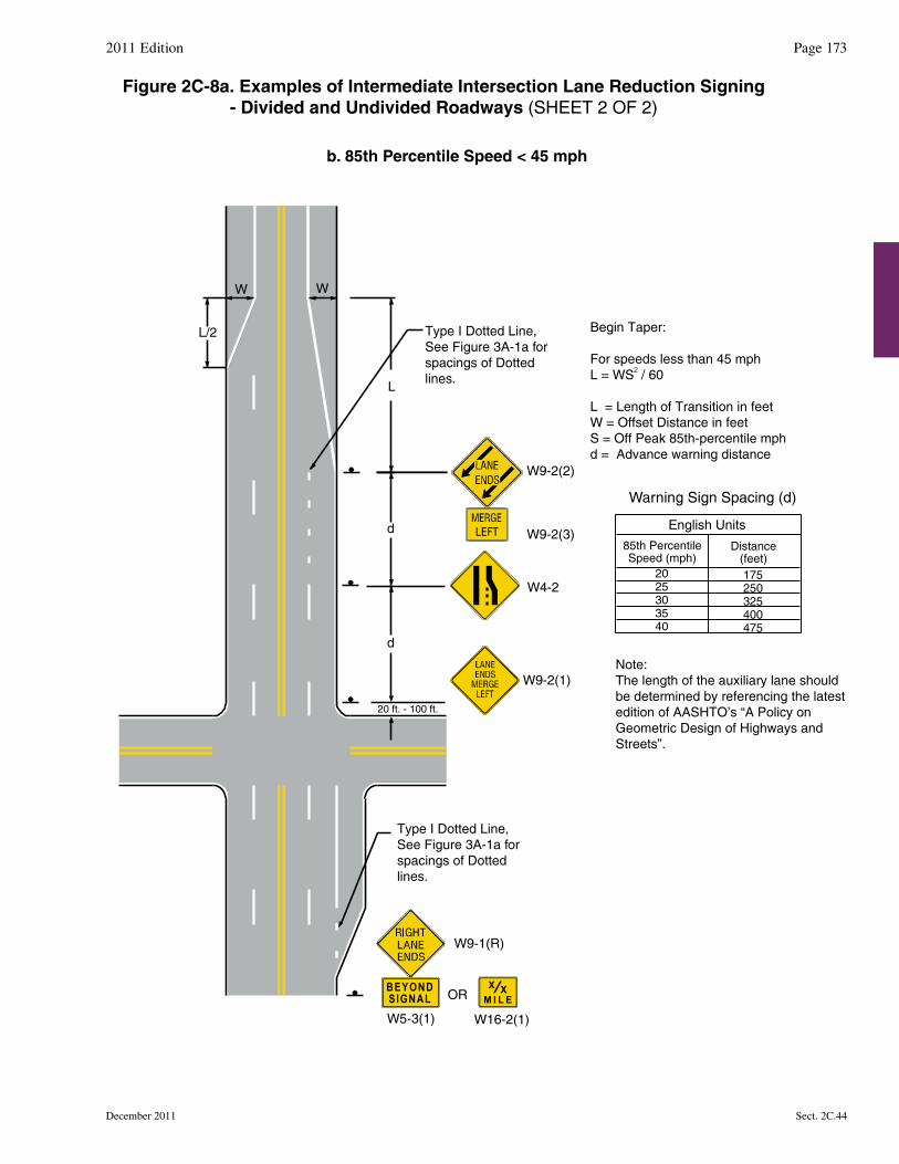
W9-2(1)
Type I Dotted Line, See Figure 3A-1a for spacings of Dottedlines.
Type I Dotted Line, See Figure 3A-1a for spacings of Dottedlines.
W W
L/2
L
d
d
20 ft. - 100 ft.
W4-2
W9-1(R)
Begin Taper:
For speeds less than 45 mphL = WS / 60
L = Length of Transition in feetW = Offset Distance in feetS = Off Peak 85th-percentile mphd = Advance warning distance
2
b. 85th Percentile Speed < 45 mph
OR
W5-3(1) W16-2(1)
BEYONDSIGNAL M I L E
X X
Note:The length of the auxiliary lane should be determined by referencing the latest edition of AASHTO’s “A Policy on Geometric Design of Highways and Streets”.
Warning Sign Spacing (d)
85th PercentileSpeed (mph)
Distance(feet)
English Units
175250325400475
2025303540
Figure 2C-8a. Examples of Intermediate Intersection Lane Reduction Signing- Divided and Undivided Roadways (SHEET 2 OF 2)
Page 1732011 Edition
Sect. 2C.44December 2011
W9-2(2)
W9-2(3)
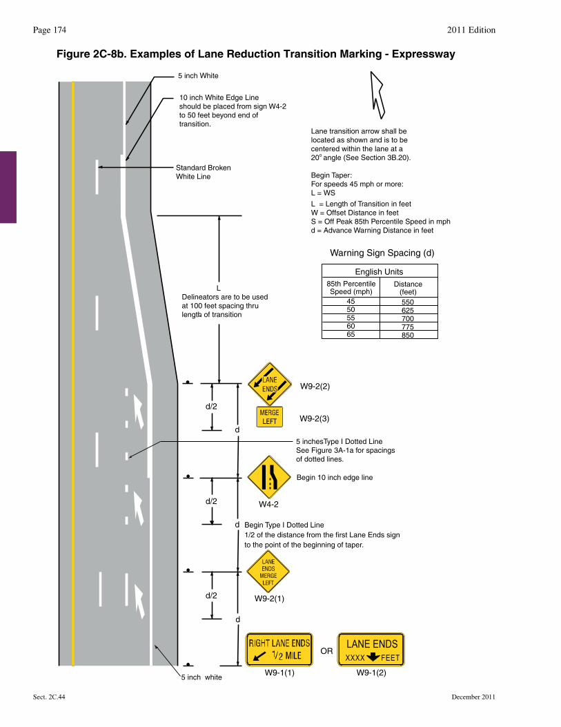
5 inch white
d/2
d/2
d/2
d
d
d
W9-1(1) W9-1(2)
LANE ENDSXXXX FEET
OR
W9-2(1)
W4-2
Begin Type I Dotted Line1/2 of the distance from the first Lane Ends signto the point of the beginning of taper.
5 inchesType I Dotted LineSee Figure 3A-1a for spacings of dotted lines.
Begin 10 inch edge line
LDelineators are to be usedat 100 feet spacing thrulength of transition
W9-2(2)
W9-2(3)
10 inch White Edge Lineshould be placed from sign W4-2to 50 feet beyond end of transition.
Lane transition arrow shall belocated as shown and is to becentered within the lane at a20 angle (See Section 3B.20).
Begin Taper:For speeds 45 mph or more:L = WS
L = Length of Transition in feetW = Offset Distance in feetS = Off Peak 85th Percentile Speed in mphd = Advance Warning Distance in feet
o
5 inch White
Standard BrokenWhite Line
Warning Sign Spacing (d)
85th PercentileSpeed (mph)
Distance(feet)
English Units
550625700775850
4550556065
Figure 2C-8b. Examples of Lane Reduction Transition Marking - Expressway
2011 EditionPage 174
December 2011Sect. 2C.44
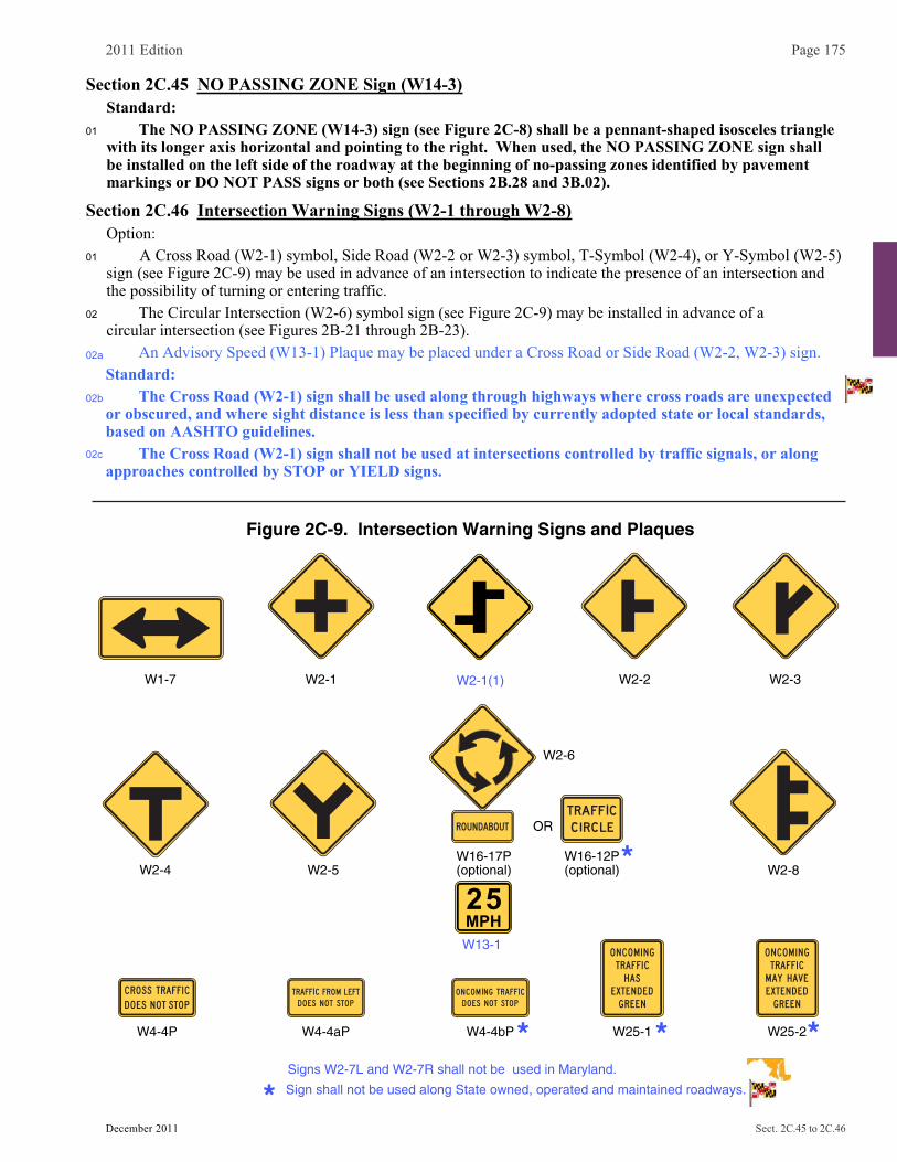
2011 Edition Page 175
December 2011 Sect. 2C.45 to 2C.46
Section 2C.45 NO PASSING ZONE Sign (W14-3)Standard:
01 The NO PASSING ZONE (W14-3) sign (see Figure 2C-8) shall be a pennant-shaped isosceles triangle with its longer axis horizontal and pointing to the right. When used, the NO PASSING ZONE sign shall be installed on the left side of the roadway at the beginning of no-passing zones identified by pavement markings or DO NOT PASS signs or both (see Sections 2B.28 and 3B.02).
Section 2C.46 Intersection Warning Signs (W2-1 through W2-8) Option: 01 A Cross Road (W2-1) symbol, Side Road (W2-2 or W2-3) symbol, T-Symbol (W2-4), or Y-Symbol (W2-5)
sign (see Figure 2C-9) may be used in advance of an intersection to indicate the presence of an intersection and the possibility of turning or entering traffic.
02
02a
02b
02c
The Circular Intersection (W2-6) symbol sign (see Figure 2C-9) may be installed in advance of a circular intersection (see Figures 2B-21 through 2B-23).
An Advisory Speed (W13-1) Plaque may be placed under a Cross Road or Side Road (W2-2, W2-3) sign. Standard: The Cross Road (W2-1) sign shall be used along through highways where cross roads are unexpected or obscured, and where sight distance is less than specified by currently adopted state or local standards, based on AASHTO guidelines. The Cross Road (W2-1) sign shall not be used at intersections controlled by traffic signals, or along approaches controlled by STOP or YIELD signs.
W2-4
W1-7 W2-1 W2-2 W2-3
W4-4P W25-2W25-1
W2-8
W4-4aP W4-4bP
Figure 2C-9. Intersection Warning Signs and Plaques
W2-5
Signs W2-7L and W2-7R shall not be used in Maryland.
W16-17P(optional)
W16-12P(optional)
W2-6
OR
W2-1(1)
W13-1
25MPH
Sign shall not be used along State owned, operated and maintained roadways.
Page 176 2009 Edition
Sect. 2C.46 to 2C.48 December 2011�
02d When used, Cross Road (W2-1) signs and modified Curve signs that indicate a cross road or a side road shall be used along�through highways with a D3 series Street Name sign, black legend on fluorescent yellow background.
02e Cross Road signs falling within curves, or within the minimum spacing listed in Section 2C.05 from a�Curve or Turn sign, shall be omitted and instead the Curve/Turn signs shall be modified to include the�appropriate width symbol for the cross road.
02f A black legend on fluorescent yellow background D-3 Series Street Name sign shall be installed under a Cross Road or Side Road�(W2-2, W2-3) sign.
02g Along state owned, operated and maintained roadways, the Circular Intersection (W2-6) symbol sign�shall be accompanied by an Advisory Speed plaque (W13-1) (see Figure 2C-9).�
Guidance:03 If an approach to a roundabout has a statutory or posted speed limit of 40 mph or higher, the Circular
Intersection (W2-6) symbol sign should be installed in advance of the circular intersection. Option: 04 An educational plaque (see Figure 2C-9) with a legend such as ROUNDABOUT (W16-17P) or TRAFFIC
CIRCLE (W16-12P) may be mounted below a Circular Intersection symbol sign. 05 The relative importance of the intersecting roadways may be shown by different widths of lines in the
symbol. 06 An advance street name plaque (see Section 2C.58) may be installed above or below an Intersection
Warning sign. Guidance:
07 The Intersection Warning sign should illustrate and depict the general configuration of the intersecting roadway, such as cross road, side road, T-intersection, or Y-intersection.
08 Intersection Warning signs, other than the Circular Intersection (W2-6) symbol sign and the T-intersection (W2-4) symbol sign should not be used on approaches controlled by STOP signs, YIELD signs, or signals.
09 If an Intersection Warning sign is used where the side roads are not opposite of each other, the Offset Side Roads (W2-1(1)) symbol sign (see Figure 2C-9) should be used instead of the Cross Road symbol sign.
10 If an Intersection Warning sign is used where two closely-spaced side roads are on the same side of the highway, the Double Side Roads (W2-8) symbol sign (see Figure 2C-9) should be used instead of the Side Road symbol sign.
11 No more than two side road symbols should be displayed on the same side of the highway on a W2-1(1)orW2-8 symbol sign, and no more than three side road symbols should be displayed on a W2-1(1)or W2-8 symbol sign.
11a The Cross Road (W2-1) sign should not be used where Route Marker Junction Assemblies are used. Support:
12 Figure 2A-4 shows the typical placement of an Intersection Warning sign.
Section 2C.47 Two-Direction Large Arrow Sign (W1-7)Standard:
01 The Two-Direction Large Arrow (W1-7) sign (see Figure 2C-9) shall be a horizontal rectangle.02 If used, it shall be installed on the far side of a T-intersection in line with, and at approximately a
right angle to, traffic approaching from the stem of the T-intersection.03 The Two-Direction Large Arrow sign shall not be used where there is no change in the direction of
travel such as at the beginnings and ends of medians or at center piers.04 The Two-Direction Large Arrow sign directing traffic to the left and right shall not be used in the
central island of a roundabout.Guidance:
05 The Two-Direction Large Arrow sign should be visible for a sufficient distance to provide the road user with adequate time to react to the intersection configuration.
Section 2C.48 Traffic Signal Signs (W25-1, W25-2) Standard:01 At locations where either a W25-1 or a W25-2 sign is required based on the provisions in Section
4D.05 the W25-1 or W25-2 sign (see Figure 2C-9) shall be installed near the left-most signal head. The W25-1 and W25-2 signs shall be vertical rectangles.
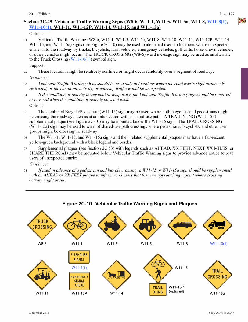
Figure 2C-10. Vehicular Traffic Warning Signs and Plaques
W11-8W8-6 W11-5 W11-5a W11-10(1)W11-1
W11-11 W11-12P W11-14
W11-15
W11-15P(optional)
W11-15a
W11-8(1)
FIREHOUSESIGNAL
2011 Edition Page 177
December 2011 Sect. 2C.46 to 2C.47
Section 2C.49 Vehicular Traffic Warning Signs (W8-6, W11-1, W11-5, W11-5a, W11-8, W11-8(1),W11-10(1), W11-11, W11-12P, W11-14, W11-15, and W11-15a)
Option: 01 Vehicular Traffic Warning (W8-6, W11-1, W11-5, W11-5a, W11-8, W11-10, W11-11, W11-12P, W11-14,
W11-15, and W11-15a) signs (see Figure 2C-10) may be used to alert road users to locations where unexpected entries into the roadway by trucks, bicyclists, farm vehicles, emergency vehicles, golf carts, horse-drawn vehicles, or other vehicles might occur. The TRUCK CROSSING (W8-6) word message sign may be used as an alternate to the Truck Crossing (W11-10(1)) symbol sign.
Support: 02 These locations might be relatively confined or might occur randomly over a segment of roadway. Guidance:03 Vehicular Traffic Warning signs should be used only at locations where the road user’s sight distance is
restricted, or the condition, activity, or entering traffic would be unexpected.04 If the condition or activity is seasonal or temporary, the Vehicular Traffic Warning sign should be removed
or covered when the condition or activity does not exist. Option: 05 The combined Bicycle/Pedestrian (W11-15) sign may be used where both bicyclists and pedestrians might
be crossing the roadway, such as at an intersection with a shared-use path. A TRAIL X-ING (W11-15P) supplemental plaque (see Figure 2C-10) may be mounted below the W11-15 sign. The TRAIL CROSSING (W11-15a) sign may be used to warn of shared-use path crossings where pedestrians, bicyclists, and other user groups might be crossing the roadway.
06 The W11-1, W11-15, and W11-15a signs and their related supplemental plaques may have a fluorescent yellow-green background with a black legend and border.
07 Supplemental plaques (see Section 2C.53) with legends such as AHEAD, XX FEET, NEXT XX MILES, or SHARE THE ROAD may be mounted below Vehicular Traffic Warning signs to provide advance notice to road users of unexpected entries. Guidance:
08 If used in advance of a pedestrian and bicycle crossing, a W11-15 or W11-15a sign should be supplemented with an AHEAD or XX FEET plaque to inform road users that they are approaching a point where crossing activity might occur.

Page 178 2009 Edition
Sect. 2C.49 to 2C.50 December 2011�
Standard:09 If a post-mounted W11-1, W11-11, W11-15, or W11-15a sign is placed at the location of the crossing
point where golf carts, pedestrians, bicyclists, or other shared-use path users might be crossing the roadway, a diagonal downward pointing arrow (W16-7P) plaque (see Figure 2C-12) shall be mounted below the sign. If the W11-1, W11-11, W11-15, or W11-15a sign is mounted overhead, the W16-7P supplemental plaque shall not be used.
Option: 05 The combined Bicycle/Pedestrian (W11-15) sign may be used where both bicyclists and pedestrians might
be crossing the roadway, such as at an intersection with a shared-use path. A TRAIL X-ING (W11-15P) supplemental plaque (see Figure 2C-10) may be mounted below the W11-15 sign. The TRAIL CROSSING (W11-15a) sign may be used to warn of shared-use path crossings where pedestrians, bicyclists, and other user groups might be crossing the roadway.
06 The W11-1, W11-15, and W11-15a signs and their related supplemental plaques may have a fluorescent yellow-green background with a black legend and border.
07 Supplemental plaques (see Section 2C.53) with legends such as AHEAD, XX FEET, NEXT XX MILES, or SHARE THE ROAD may be mounted below Vehicular Traffic Warning signs to provide advance notice to road users of unexpected entries. Guidance:
08 If used in advance of a pedestrian and bicycle crossing, a W11-15 or W11-15a sign should be supplemented with an AHEAD or XX FEET plaque to inform road users that they are approaching a point where crossing activity might occur.Standard:
09 If a post-mounted W11-1, W11-11, W11-15, or W11-15a sign is placed at the location of the crossing point where golf carts, pedestrians, bicyclists, or other shared-use path users might be crossing the roadway, a diagonal downward pointing arrow (W16-7P) plaque (see Figure 2C-12) shall be mounted below the sign. If the W11-1, W11-11, W11-15, or W11-15a sign is mounted overhead, the W16-7P supplemental plaque shall not be used.Option:
10 The crossing location identified by a W11-1, W11-11, W11-15, or W11-15a sign may be defined with crosswalk markings (see Section 3B.18).
Standard:11 The Emergency Vehicle (W11-8) sign (see Figure 2C-10) with the EMERGENCY SIGNAL AHEAD
(W11-12P) supplemental plaque (see Figure 2C-10) shall be placed in advance of all emergency-vehicle traffic control signals (see Chapter 4G).
Option: 12 The Emergency Vehicle (W11-8) sign, or a word message sign indicating the type of emergency vehicle
(such as rescue squad), may be used in advance of the emergency-vehicle station when no emergency-vehicle traffic control signal is present.
13 A Warning Beacon (see Section 4L.03) may be used with any Vehicular Traffic Warning sign to indicate specific periods when the condition or activity is present or is likely to be present, or to provide enhanced sign conspicuity.
14 A supplemental WHEN FLASHING (W16-13P) plaque (see Figure 2C-12) may be used with any Vehicular Traffic Warning sign that is supplemented with a Warning Beacon to indicate specific periods when the condition or activity is present or is likely to be present.
Section 2C.50 Non-Vehicular Warning Signs (W11-2, W11-3, W11-4, W11-6, W11-7, W11-9, and W11-16 through W11-22)
Option: 01 Non-Vehicular Warning (W11-2, W11-3, W11-4, W11-6, W11-7, W11-9, and W11-16 through W11-22)
signs (see Figure 2C-11) may be used to alert road users in advance of locations where unexpected entries into the roadway might occur or where shared use of the roadway by pedestrians, animals, or equestrians might occur.
Support: 02 These conflicts might be relatively confined, or might occur randomly over a segment of roadway.
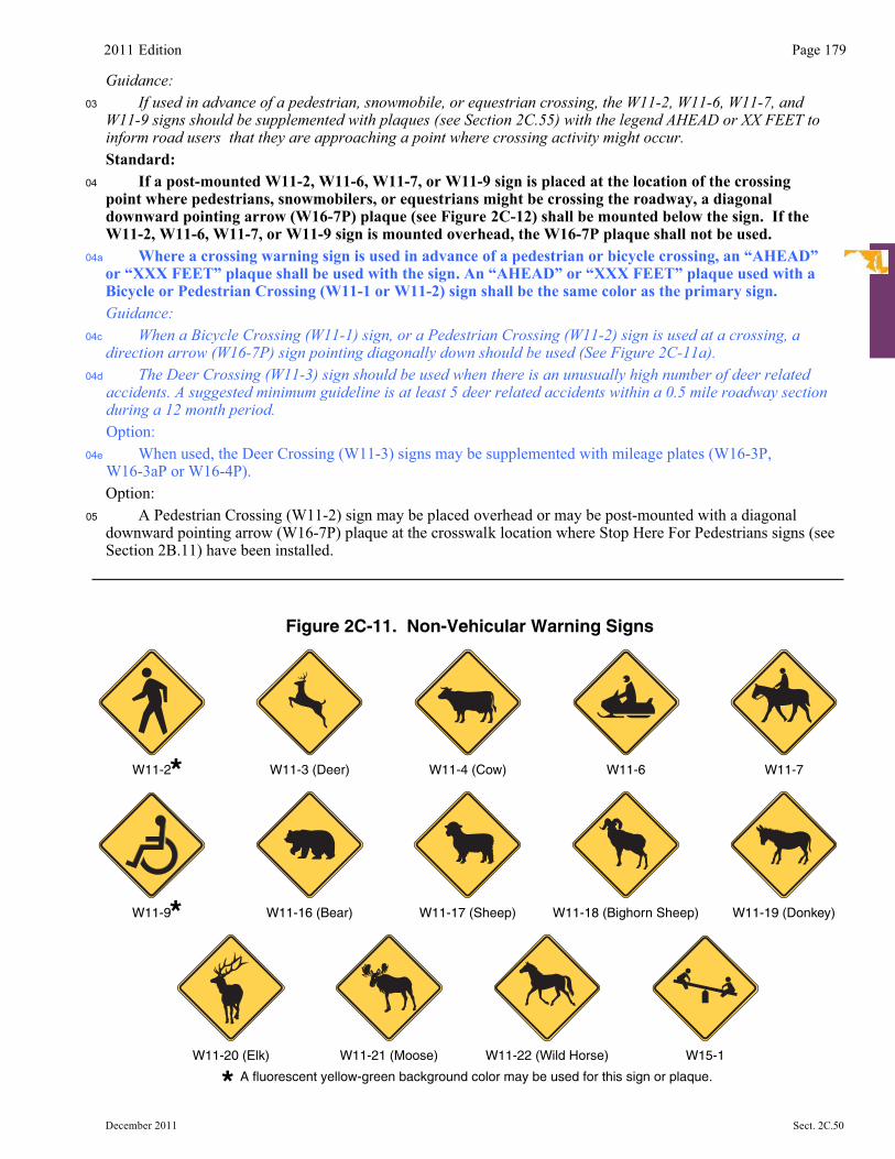
2011 Edition Page 179
December 2011 Sect. 2C.50
Guidance:03 If used in advance of a pedestrian, snowmobile, or equestrian crossing, the W11-2, W11-6, W11-7, and
W11-9 signs should be supplemented with plaques (see Section 2C.55) with the legend AHEAD or XX FEET to inform road users that they are approaching a point where crossing activity might occur.
Standard: 04 If a post-mounted W11-2, W11-6, W11-7, or W11-9 sign is placed at the location of the crossing
point where pedestrians, snowmobilers, or equestrians might be crossing the roadway, a diagonal downward pointing arrow (W16-7P) plaque (see Figure 2C-12) shall be mounted below the sign. If the W11-2, W11-6, W11-7, or W11-9 sign is mounted overhead, the W16-7P plaque shall not be used.
04a Where a crossing warning sign is used in advance of a pedestrian or bicycle crossing, an “AHEAD” or “XXX FEET” plaque shall be used with the sign. An “AHEAD” or “XXX FEET” plaque used with a Bicycle or Pedestrian Crossing (W11-1 or W11-2) sign shall be the same color as the primary sign. Guidance:
04c When a Bicycle Crossing (W11-1) sign, or a Pedestrian Crossing (W11-2) sign is used at a crossing, a direction arrow (W16-7P) sign pointing diagonally down should be used (See Figure 2C-11a).
04d The Deer Crossing (W11-3) sign should be used when there is an unusually high number of deer related accidents. A suggested minimum guideline is at least 5 deer related accidents within a 0.5 mile roadway section during a 12 month period.
Option: 04e When used, the Deer Crossing (W11-3) signs may be supplemented with mileage plates (W16-3P,
W16-3aP or W16-4P). Option:
05 A Pedestrian Crossing (W11-2) sign may be placed overhead or may be post-mounted with a diagonal downward pointing arrow (W16-7P) plaque at the crosswalk location where Stop Here For Pedestrians signs (see Section 2B.11) have been installed.
Figure 2C-11. Non-Vehicular Warning Signs
A fluorescent yellow-green background color may be used for this sign or plaque.
W11-3 (Deer) W11-4 (Cow) W11-6 W11-7W11-2
W11-16 (Bear) W11-18 (Bighorn Sheep) W11-19 (Donkey)W11-17 (Sheep)W11-9
W11-22 (Wild Horse)W11-20 (Elk) W11-21 (Moose) W15-1
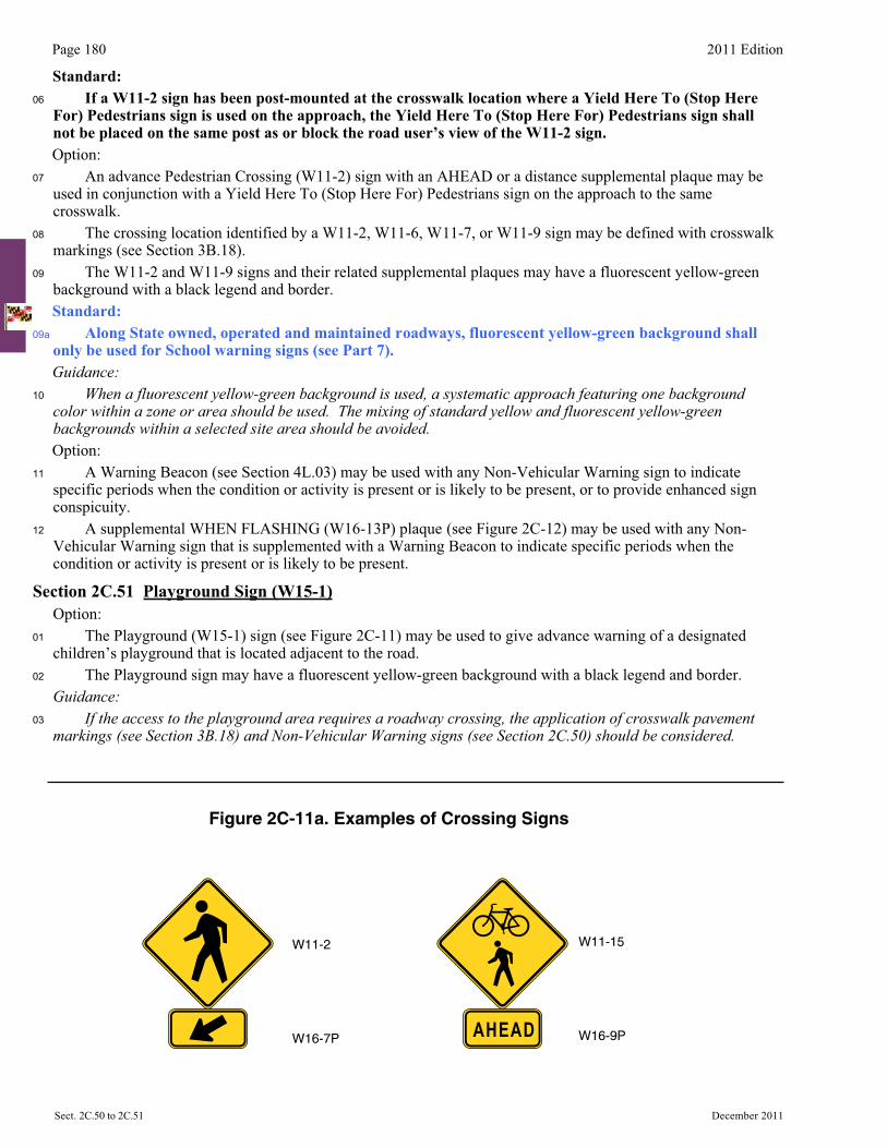
Page 180 2011 Edition
Sect. 2C.50 to 2C.51 December 2011
Standard:06 If a W11-2 sign has been post-mounted at the crosswalk location where a Yield Here To (Stop Here
For) Pedestrians sign is used on the approach, the Yield Here To (Stop Here For) Pedestrians sign shall not be placed on the same post as or block the road user’s view of the W11-2 sign.Option:
07 An advance Pedestrian Crossing (W11-2) sign with an AHEAD or a distance supplemental plaque may be used in conjunction with a Yield Here To (Stop Here For) Pedestrians sign on the approach to the same crosswalk.
08 The crossing location identified by a W11-2, W11-6, W11-7, or W11-9 sign may be defined with crosswalk markings (see Section 3B.18).
09
09a
The W11-2 and W11-9 signs and their related supplemental plaques may have a fluorescent yellow-green background with a black legend and border. Standard:
Along State owned, operated and maintained roadways, fluorescent yellow-green background shall only be used for School warning signs (see Part 7). Guidance:
10 When a fluorescent yellow-green background is used, a systematic approach featuring one background color within a zone or area should be used. The mixing of standard yellow and fluorescent yellow-green backgrounds within a selected site area should be avoided.Option:
11 A Warning Beacon (see Section 4L.03) may be used with any Non-Vehicular Warning sign to indicate specific periods when the condition or activity is present or is likely to be present, or to provide enhanced sign conspicuity.
12 A supplemental WHEN FLASHING (W16-13P) plaque (see Figure 2C-12) may be used with any Non-Vehicular Warning sign that is supplemented with a Warning Beacon to indicate specific periods when the condition or activity is present or is likely to be present.
Section 2C.51 Playground Sign (W15-1) Option: 01 The Playground (W15-1) sign (see Figure 2C-11) may be used to give advance warning of a designated
children’s playground that is located adjacent to the road. 02 The Playground sign may have a fluorescent yellow-green background with a black legend and border. Guidance:03 If the access to the playground area requires a roadway crossing, the application of crosswalk pavement
markings (see Section 3B.18) and Non-Vehicular Warning signs (see Section 2C.50) should be considered.
W11-2
W16-7P
W11-15
W16-9PAHEAD
Figure 2C-11a. Examples of Crossing Signs
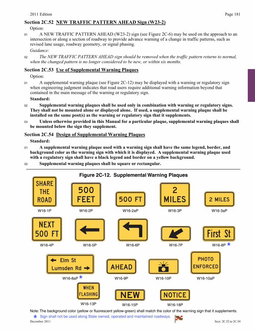
2011 Edition Page 181
December 2011 Sect. 2C.52 to 2C.54
Section 2C.52 NEW TRAFFIC PATTERN AHEAD Sign (W23-2)Option:
01 A NEW TRAFFIC PATTERN AHEAD (W23-2) sign (see Figure 2C-6) may be used on the approach to an intersection or along a section of roadway to provide advance warning of a change in traffic patterns, such as revised lane usage, roadway geometry, or signal phasing. Guidance:
02 The NEW TRAFFIC PATTERN AHEAD sign should be removed when the traffic pattern returns to normal, when the changed pattern is no longer considered to be new, or within six months.
Section 2C.53 Use of Supplemental Warning Plaques Option: 01 A supplemental warning plaque (see Figure 2C-12) may be displayed with a warning or regulatory sign
when engineering judgment indicates that road users require additional warning information beyond that contained in the main message of the warning or regulatory sign.
Standard:02 Supplemental warning plaques shall be used only in combination with warning or regulatory signs.
They shall not be mounted alone or displayed alone. If used, a supplemental warning plaque shall be installed on the same post(s) as the warning or regulatory sign that it supplements.
03 Unless otherwise provided in this Manual for a particular plaque, supplemental warning plaques shall be mounted below the sign they supplement.
Section 2C.54 Design of Supplemental Warning Plaques Standard:01 A supplemental warning plaque used with a warning sign shall have the same legend, border, and
background color as the warning sign with which it is displayed. A supplemental warning plaque used with a regulatory sign shall have a black legend and border on a yellow background.
02 Supplemental warning plaques shall be square or rectangular.
W16-2P W16-2aP W16-3P W16-3aPW16-1P
W16-4P W16-5P W16-6P W16-7P W16-8P
Figure 2C-12. Supplemental Warning Plaques
W16-10aPW16-9PW16-8aP W16-10P
Note: The background color (yellow or fluorescent yellow-green) shall match the color of the warning sign that it supplements.
W16-13P W16-15P W16-18P
Sign shall not be used along State owned, operated and maintained roadways.
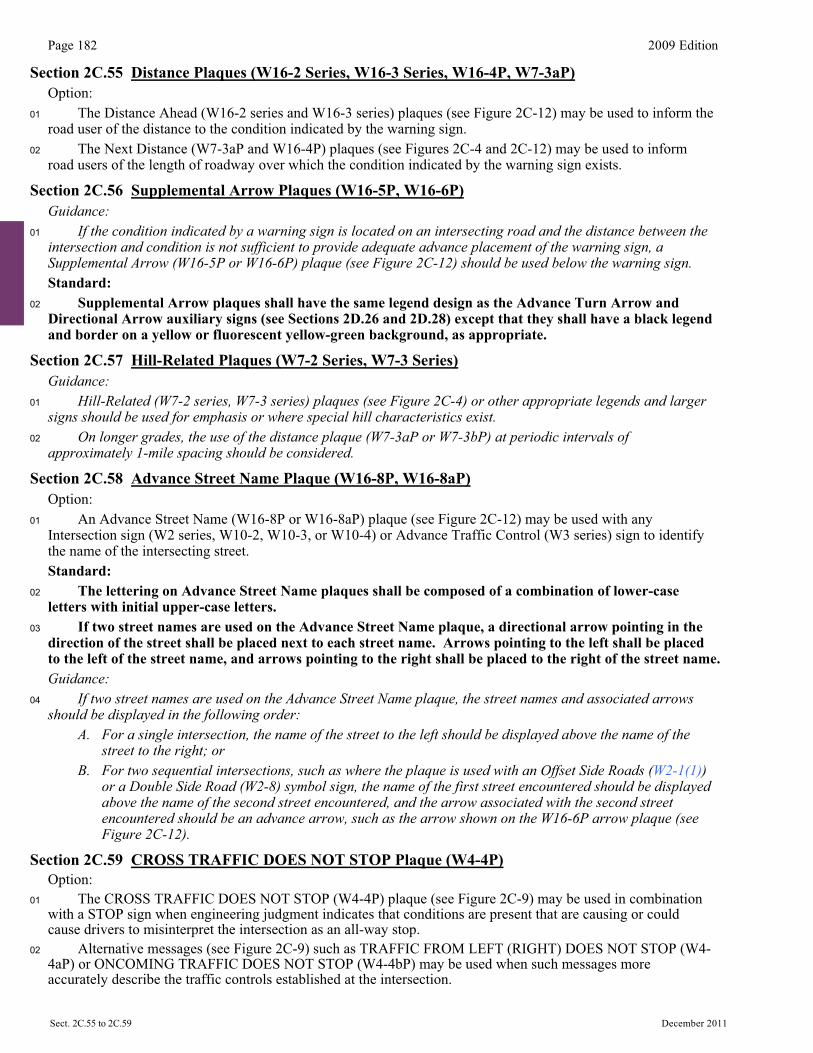
Page 182 2009 Edition
Sect. 2C.55 to 2C.59 December 2011�
Section 2C.55 Distance Plaques (W16-2 Series, W16-3 Series, W16-4P, W7-3aP) Option: 01 The Distance Ahead (W16-2 series and W16-3 series) plaques (see Figure 2C-12) may be used to inform the
road user of the distance to the condition indicated by the warning sign. 02 The Next Distance (W7-3aP and W16-4P) plaques (see Figures 2C-4 and 2C-12) may be used to inform
road users of the length of roadway over which the condition indicated by the warning sign exists.
Section 2C.56 Supplemental Arrow Plaques (W16-5P, W16-6P) Guidance:01 If the condition indicated by a warning sign is located on an intersecting road and the distance between the
intersection and condition is not sufficient to provide adequate advance placement of the warning sign, a Supplemental Arrow (W16-5P or W16-6P) plaque (see Figure 2C-12) should be used below the warning sign.
Standard:02 Supplemental Arrow plaques shall have the same legend design as the Advance Turn Arrow and
Directional Arrow auxiliary signs (see Sections 2D.26 and 2D.28) except that they shall have a black legend and border on a yellow or fluorescent yellow-green background, as appropriate.
Section 2C.57 Hill-Related Plaques (W7-2 Series, W7-3 Series) Guidance:01 Hill-Related (W7-2 series, W7-3 series) plaques (see Figure 2C-4) or other appropriate legends and larger
signs should be used for emphasis or where special hill characteristics exist.02 On longer grades, the use of the distance plaque (W7-3aP or W7-3bP) at periodic intervals of
approximately 1-mile spacing should be considered.
Section 2C.58 Advance Street Name Plaque (W16-8P, W16-8aP) Option: 01 An Advance Street Name (W16-8P or W16-8aP) plaque (see Figure 2C-12) may be used with any
Intersection sign (W2 series, W10-2, W10-3, or W10-4) or Advance Traffic Control (W3 series) sign to identify the name of the intersecting street.
Standard:02 The lettering on Advance Street Name plaques shall be composed of a combination of lower-case
letters with initial upper-case letters.03 If two street names are used on the Advance Street Name plaque, a directional arrow pointing in the
direction of the street shall be placed next to each street name. Arrows pointing to the left shall be placed to the left of the street name, and arrows pointing to the right shall be placed to the right of the street name.
Guidance:04 If two street names are used on the Advance Street Name plaque, the street names and associated arrows
should be displayed in the following order:A. For a single intersection, the name of the street to the left should be displayed above the name of the
street to the right; orB. For two sequential intersections, such as where the plaque is used with an Offset Side Roads (W2-1(1))
or a Double Side Road (W2-8) symbol sign, the name of the first street encountered should be displayed above the name of the second street encountered, and the arrow associated with the second street encountered should be an advance arrow, such as the arrow shown on the W16-6P arrow plaque (see Figure 2C-12).
Section 2C.59 CROSS TRAFFIC DOES NOT STOP Plaque (W4-4P) Option: 01 The CROSS TRAFFIC DOES NOT STOP (W4-4P) plaque (see Figure 2C-9) may be used in combination
with a STOP sign when engineering judgment indicates that conditions are present that are causing or could cause drivers to misinterpret the intersection as an all-way stop.
02 Alternative messages (see Figure 2C-9) such as TRAFFIC FROM LEFT (RIGHT) DOES NOT STOP (W4-4aP) or ONCOMING TRAFFIC DOES NOT STOP (W4-4bP) may be used when such messages more accurately describe the traffic controls established at the intersection.

2011 Edition Page 183
December 2011 Sect. 2C.59 to 2C.63�
Guidance: 03 Plaques with the appropriate alternative messages of TRAFFIC FROM LEFT (RIGHT) DOES NOT STOP
or ONCOMING TRAFFIC DOES NOT STOP should be used at intersections where STOP signs control all but one approach to the intersection, unless the only non-stopped approach is from a one-way street.
Standard:04 If a W4-4P plaque or a plaque with an alternative message is used, it shall be mounted below the
STOP sign.
Section 2C.60 SHARE THE ROAD Plaque (W16-1P) Option: 01 In situations where there is a need to warn drivers to watch for other slower forms of transportation
traveling along the highway, such as bicycles, golf carts, horse-drawn vehicles, or farm machinery, a SHARE THE ROAD (W16-1P) plaque (see Figure 2C-12) may be used. Standard:
02 A W16-1P plaque shall not be used alone. If a W16-1P plaque is used, it shall be mounted below either a Vehicular Traffic Warning sign (see Section 2C.49) or a Non-Vehicular Warning sign (see Section 2C.50). The background color of the W16-1P plaque shall match the background color of the warning sign with which it is displayed.
Section 2C.61 Photo Enforced Plaque (W16-10P) Option: 01 A Photo Enforced (W16-10P) plaque or a PHOTO ENFORCED (W16-10aP) word message plaque (see
Figure 2C-12) may be mounted below a warning sign to advise road users that the regulations associated with the condition being warned about (such as a traffic control signal or a toll plaza) are being enforced by photographic equipment.
Standard:02 If used below a warning sign, the Photo Enforced (W16-10P or W16-10aP) plaque shall be a rectangle
with a black legend and border on a yellow background.
Section 2C.62 NEW Plaque (W16-15P) Option: 01 A NEW (W16-15P) plaque (see Figure 2C-12) may be mounted above a regulatory sign when a new
regulation takes effect in order to alert road users to the new traffic regulation. A NEW plaque may also be mounted above an advance warning sign (such as a Signal Ahead sign for a newly-installed traffic control signal) for a new traffic regulation.
Standard:02 The NEW plaque shall not be used alone.03 The NEW plaque shall be removed no later than 6 months after the regulation has been in effect.
Section 2C.63 Object Marker Design and Placement Height Support: 01 Type 1, 2, and 3 object markers are used to mark obstructions within or adjacent to the roadway. Type 4
object markers are used to mark the end of a roadway. Standard:02 When used, object markers (see Figure 2C-13) shall not have a border and shall consist of an
arrangement of one or more of the following types:Type 1—a diamond-shaped sign, at least 18 inches on a side, consisting of either a yellow (OM1-1) or
black (OM1-2) sign with nine yellow retroreflective devices, each with a minimum diameter of 3 inches, mounted symmetrically on the sign, or an all-yellow retroreflective sign (OM1-3).
Type 2—either a marker (OM2-1V or OM2-1H) consisting of three yellow retroreflective devices, each with a minimum diameter of 3 inches, arranged either horizontally or vertically on a white sign measuring at least 6 x 12 inches; or an all-yellow horizontal or vertical retroreflective sign (OM2-2V or OM2-2H), measuring at least 6 x 12 inches.
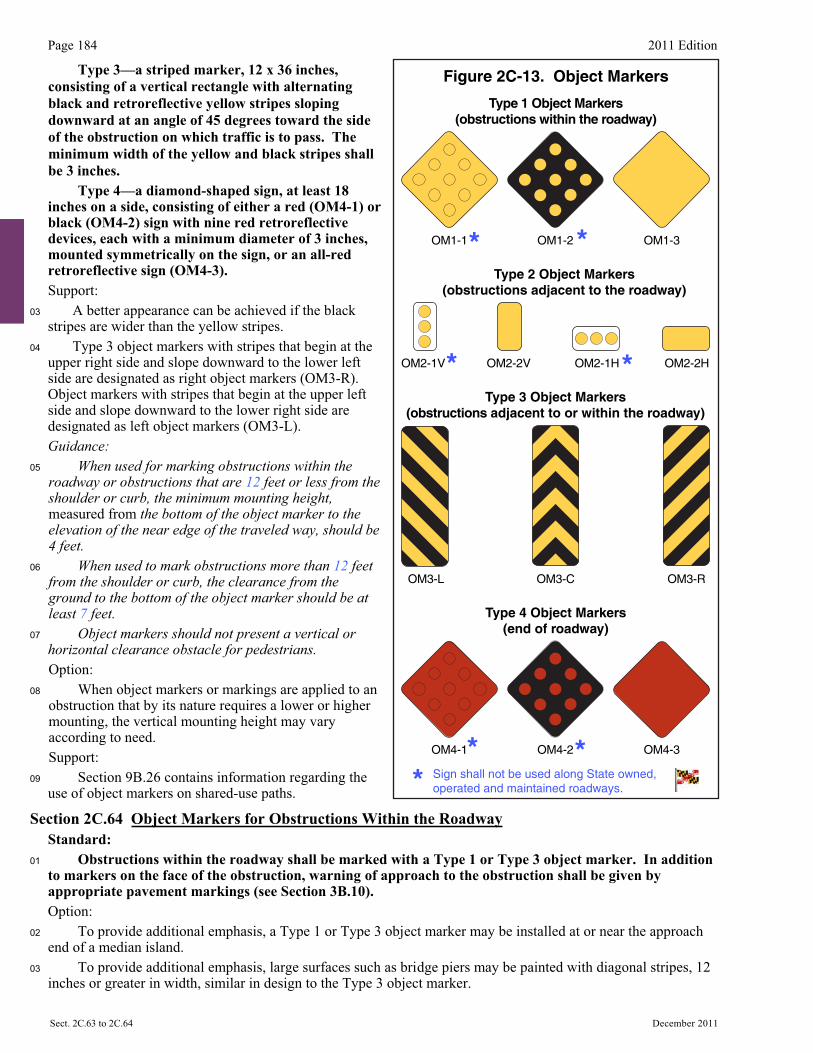
Page 184 2011 Edition
Sect. 2C.63 to 2C.64 December 2011
Type 3—a striped marker, 12 x 36 inches, consisting of a vertical rectangle with alternating black and retroreflective yellow stripes sloping downward at an angle of 45 degrees toward the side of the obstruction on which traffic is to pass. The minimum width of the yellow and black stripes shall be 3 inches.
Type 4—a diamond-shaped sign, at least 18 inches on a side, consisting of either a red (OM4-1) or black (OM4-2) sign with nine red retroreflective devices, each with a minimum diameter of 3 inches, mounted symmetrically on the sign, or an all-red retroreflective sign (OM4-3).Support:
03 A better appearance can be achieved if the black stripes are wider than the yellow stripes.
04 Type 3 object markers with stripes that begin at the upper right side and slope downward to the lower left side are designated as right object markers (OM3-R). Object markers with stripes that begin at the upper left side and slope downward to the lower right side are designated as left object markers (OM3-L). Guidance:
05 When used for marking obstructions within the roadway or obstructions that are 12 feet or less from the shoulder or curb, the minimum mounting height, measured from the bottom of the object marker to the elevation of the near edge of the traveled way, should be4 feet.
06 When used to mark obstructions more than 12 feet from the shoulder or curb, the clearance from the ground to the bottom of the object marker should be at least 7 feet.
07 Object markers should not present a vertical or horizontal clearance obstacle for pedestrians.Option:
08 When object markers or markings are applied to an obstruction that by its nature requires a lower or higher mounting, the vertical mounting height may vary according to need. Support:
09 Section 9B.26 contains information regarding the use of object markers on shared-use paths.
Section 2C.64 Object Markers for Obstructions Within the Roadway Standard:01 Obstructions within the roadway shall be marked with a Type 1 or Type 3 object marker. In addition
to markers on the face of the obstruction, warning of approach to the obstruction shall be given by appropriate pavement markings (see Section 3B.10).
Option: 02 To provide additional emphasis, a Type 1 or Type 3 object marker may be installed at or near the approach
end of a median island. 03 To provide additional emphasis, large surfaces such as bridge piers may be painted with diagonal stripes, 12
inches or greater in width, similar in design to the Type 3 object marker.
Figure 2C-13. Object Markers
Type 4 Object Markers(end of roadway)
OM4-1 OM4-2 OM4-3
Type 1 Object Markers(obstructions within the roadway)
OM1-3OM1-2OM1-1
Type 2 Object Markers(obstructions adjacent to the roadway)
OM2-2V OM2-1H OM2-2HOM2-1V
Type 3 Object Markers(obstructions adjacent to or within the roadway)
OM3-L OM3-ROM3-C
Sign shall not be used along State owned, operated and maintained roadways.

2011 Edition Page 185
December 2011 Sect. 2C.64 to 2C.67
Standard:04 The alternating black and retroreflective yellow stripes (OM3-L, OM3-R) shall be sloped down at an
angle of 45 degrees toward the side on which traffic is to pass the obstruction. If traffic can pass to either side of the obstruction, the alternating black and retroreflective yellow stripes (OM3-C) shall form chevrons that point upwards.
Option: 05 Appropriate signs (see Sections 2B.32 and 2C.25) directing traffic to one or both sides of the obstruction
may be used instead of the object marker.
Section 2C.65 Object Markers for Obstructions Adjacent to the Roadway Support: 01 Obstructions not actually within the roadway are sometimes so close to the edge of the road that they need a
marker. These include underpass piers, bridge abutments, handrails, ends of traffic barriers, utility poles, and culvert headwalls. In other cases there might not be a physical object involved, but other roadside conditions exist, such as narrow shoulders, drop-offs, gores, small islands, and abrupt changes in the roadway alignment, that might make it undesirable for a road user to leave the roadway, and therefore would create a need for a marker.
Standard:02 If a Type 2 or Type 3 object marker is used to mark an obstruction adjacent to the roadway, the edge
of the object marker that is closest to the road user shall be installed in line with the closest edge of the obstruction.
03 Where Type 3 object markers are applied to the approach ends of guardrail and other roadside appurtenances, sheeting without a substrate shall be directly affixed to the approach end of the guardrail in a rectangular shape conforming to the size of the approach end of the guardrail with alternating black and retroreflective yellow stripes sloping downward at a angle of 45 degrees toward the side of the obstruction on which traffic is to pass.
04 Type 1 and Type 4 object markers shall not be used to mark obstructions adjacent to the roadway. Guidance:05 Standard warning signs in this Chapter should also be used where applicable.
Section 2C.66 Object Markers for Ends of Roadways Support: 01 The Type 4 object marker is used to warn and alert road users of the end of a roadway in other than
construction or maintenance areas. Standard:02 If an object marker is used to mark the end of a roadway, a Type 4 object marker shall be used.
Option: 03 The Type 4 object marker may be used in instances where there are no alternate vehicular paths. 04 Where conditions warrant, more than one marker, or a larger marker with or without a Type 3 Barricade (see
Section 2B.67), may be used at the end of the roadway. Standard:05 The minimum mounting height, measured vertically from the bottom of a Type 4 object marker to the
elevation of the near edge of the traveled way, shall be 4 feet. Guidance:06 Appropriate advance warning signs in this Chapter should be used.
Section 2C.67 OTHER WARNING SIGN (W8-1(1))Support:
00a The Low Trucks Bottom Out (W8-1(1)) sign is used to give warning of a sharp rise or depression in the profile of the road that is sufficiently abrupt to create a hazardous condition that might cause a vehicle to bottom out. Guidance:
00b The Low Trucks Bottom Out (W8-1(1)) sign should only be used in the interim before milling or geometric improvements can be accomplished (see Figure 2C-13a). W8-1(1)
Figure 2C-13a. Low Trucks Bottom Out Sign