chapter 3 experimental conditions and procedure...
TRANSCRIPT
50
CHAPTER 3
EXPERIMENTAL CONDITIONS AND PROCEDURE
This study was undertaken to perform milling operations on
AISI D2, AISI D3, AISI H13 and AISI P20 steels, using different carbide
cutting tool inserts under various speed-feed combinations. The experiment
was performed under a constant depth of cut. The cutting environments
evaluated in the milling process were: Dry machining, Conventional cooling
(Wet) and Cryogenic cooling (LN2). A cryogenic cooling setup was
developed for supplying liquid nitrogen at the cutting zone. In the present
work, the cutting temperature, cutting force, surface roughness, tool wear,
chip shape and chip morphology are considered, for studying the effect of
cryogenic cooling. The influence of cryogenic cooling using liquid nitrogen
was compared to that of dry and wet machining. This chapter explains
experimental procedure, workpiece materials, cutting tool materials and the
equipment being used.
3.1 WORK MATERIALS
Tool and die steels are high carbon steels, possessing high
hardness, strength and wear resistance. Materials having a hardness of
over 45 HRC (Rockwell hardness C scale), can be classified as
difficult-to-machine materials (Becze and Elbestawi 2002, Poulachon and
Moisan, 2000). The four most widely used die steel materials by the tool and
mould making industry, have been chosen as work materials for this
experimental work. These are High Carbon High Chromium (HC-HCr) type
51
AISI D2 die steel, High Carbon High Chromium (HC-HCr) type AISI D3 die
steel, hot work type AISI H13 die steel and plastic mold type AISI P20 steel.
The workpieces made from these four die steel materials were hardened and
tempered using standard heat treatment procedures before experimentation, to
bring them on par with the state in which they are actually used in the
industry. In this research work, the size of the work materials used was
150mm × 100mm × 50mm. The work materials were tested for their
composition, and the mechanical properties for homogeneity.
3.1.1 AISI D2 Steel
AISI D2 steel is a high-carbon high-chromium tool steel,
designated as a group ‘D’ steel in the AISI classification system, and is the
most highly alloyed cold-work tool steel. Chromium, at a nominal
concentration of 12%, is the major alloying element, but molybdenum,
vanadium, nickel, and manganese may be added in significant amounts. In
view of their high carbon and alloy contents, all the D steels are deep
hardening. They are hardenable by air cooling from austenitizing
temperatures, and they have very low susceptibility to distortion and cracking
(ASM Specialty Handbook, 1995, Roberts and Cary, 1980). The D2 type
HC-HCr tool steels find wide usage as the raw material for blanking and deep
drawing dies, thread rolling & forming dies, burnishing tools, shear and slitter
knives. The chemical composition of the AISI D2 steel is given in Table 3.1,
and its properties are given in Table 3.2.
52
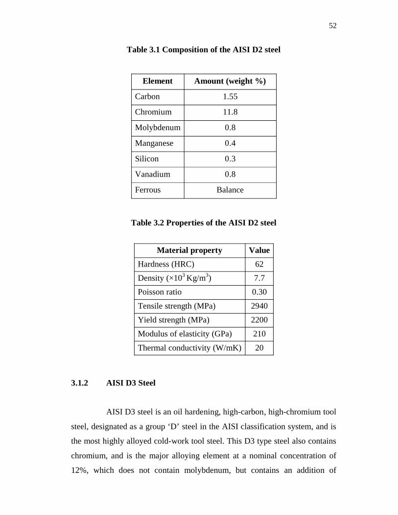
Table 3.1 Composition of the AISI D2 steel
Element Amount (weight %)
Carbon 1.55
Chromium 11.8
Molybdenum 0.8
Manganese 0.4
Silicon 0.3
Vanadium 0.8
Ferrous Balance
Table 3.2 Properties of the AISI D2 steel
Material property ValueHardness (HRC) 62
Density (×103 Kg/m3) 7.7
Poisson ratio 0.30
Tensile strength (MPa) 2940
Yield strength (MPa) 2200
Modulus of elasticity (GPa) 210
Thermal conductivity (W/mK) 20
3.1.2 AISI D3 Steel
AISI D3 steel is an oil hardening, high-carbon, high-chromium tool
steel, designated as a group ‘D’ steel in the AISI classification system, and is
the most highly alloyed cold-work tool steel. This D3 type steel also contains
chromium, and is the major alloying element at a nominal concentration of
12%, which does not contain molybdenum, but contains an addition of
53
tungsten. The oil hardening D3 steel offers the advantage of a better surface
condition, because a combination of lower hardening temperature and liquid
quenching resulting in minimum surface decarburization and scaling. It has an
excellent abrasion/wear resistance, good dimensional stability and high
compressive strength. The high chromium content of these steels provides an
appreciable resistance to staining, after the tools are hardened and polished. It
is widely used for blanking and forming dies, forming rolls, press tools,
punches and bushes. The chemical composition of the AISI D3 steel is given
in Table 3.3, and its properties are given in Table 3.4.
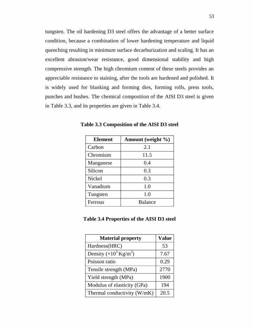
Table 3.3 Composition of the AISI D3 steel
Element Amount (weight %)Carbon 2.1Chromium 11.5Manganese 0.4Silicon 0.3Nickel 0.3Vanadium 1.0Tungsten 1.0Ferrous Balance
Table 3.4 Properties of the AISI D3 steel
Material property ValueHardness(HRC) 53Density (×103 Kg/m3) 7.67Poisson ratio 0.29Tensile strength (MPa) 2770Yield strength (MPa) 1900Modulus of elasticity (GPa) 194Thermal conductivity (W/mK) 20.5
54
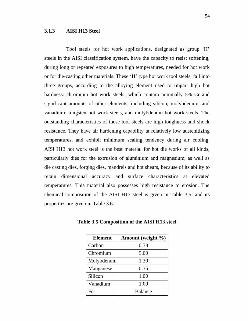
3.1.3 AISI H13 Steel
Tool steels for hot work applications, designated as group ‘H’
steels in the AISI classification system, have the capacity to resist softening,
during long or repeated exposures to high temperatures, needed for hot work
or for die-casting other materials. These ‘H’ type hot work tool steels, fall into
three groups, according to the alloying element used to impart high hot
hardness: chromium hot work steels, which contain nominally 5% Cr and
significant amounts of other elements, including silicon, molybdenum, and
vanadium; tungsten hot work steels, and molybdenum hot work steels. The
outstanding characteristics of these tool steels are high toughness and shock
resistance. They have air hardening capability at relatively low austenitizing
temperatures, and exhibit minimum scaling tendency during air cooling.
AISI H13 hot work steel is the best material for hot die works of all kinds,
particularly dies for the extrusion of aluminium and magnesium, as well as
die casting dies, forging dies, mandrels and hot shears, because of its ability to
retain dimensional accuracy and surface characteristics at elevated
temperatures. This material also possesses high resistance to erosion. The
chemical composition of the AISI H13 steel is given in Table 3.5, and its
properties are given in Table 3.6.
Table 3.5 Composition of the AISI H13 steel
Element Amount (weight %)Carbon 0.38Chromium 5.00Molybdenum 1.30Manganese 0.35Silicon 1.00Vanadium 1.00Fe Balance

55
Table 3.6 Properties of the AISI H13 steel
Material property Value
Hardness (HRC) 52
Density (×103 Kg/m3) 7.8
Poisson ratio 0.29
Tensile strength (MPa) 1990
Yield strength (MPa) 1650
Modulus of elasticity (GPa) 203
Thermal conductivity (W/mK) 24.6
3.1.4 AISI P20 Steel
Tool steels for plastic injection molding and die casting
applications, designated as group ‘P’ steels in the AISI classification system,
are exposed to less severe wear than metal-working steels, and therefore, have
low carbon content. There are three major groups of ‘P’ type steels: carbon
steel grades used for hubbed cavities, carbon steel grades used for machined
cavities, and stainless steel grades. Plastic moulds for thermoplastics and
thermosets are typically made from cold work tool steel like AISI P20 tool
steels. It has properties like excellent machinability and weldability,
combined with good corrosion resistance and mechanical strength. AISI P20
steel finds application in injection moulds for thermo-plastics, extrusion dies
for thermo-plastics, blow moulds, forming tools, press-brake dies, (possibly
flame hardened or nitrided) and structural components. The chemical
composition of the AISI P20 steel is given in Table 3.7, and its properties are
given in Table 3.8.

56
Table 3.7 Composition of the AISI P20 steel
Element Amount (weight %)
Carbon 0.4
Chromium 1.2
Molybdenum 0.35
Manganese 1.0
Silicon 0.4
Nickel 0.8
sulphur 0.08
Ferrous Balance
Table 3.8 Properties of the AISI P20 steel
Material property Value
Hardness (HRC) 48
Density (×103 Kg/m3) 7.8
Poisson ratio 0.28
Tensile strength (MPa) 1310
Yield strength (MPa) 1172
Modulus of elasticity (GPa) 205
Thermal conductivity (W/mK) 20.2
3.2 CUTTING TOOL INSERTS
In this research work, indexable inserts are used as cutting tools.
Three different types of carbide cutting tool inserts have been used in the
research work. They are: i) CVD TiN coated carbide cutting tool insert ii)
PVD TiAlN coated carbide cutting tool insert and iii) Uncoated carbide
57
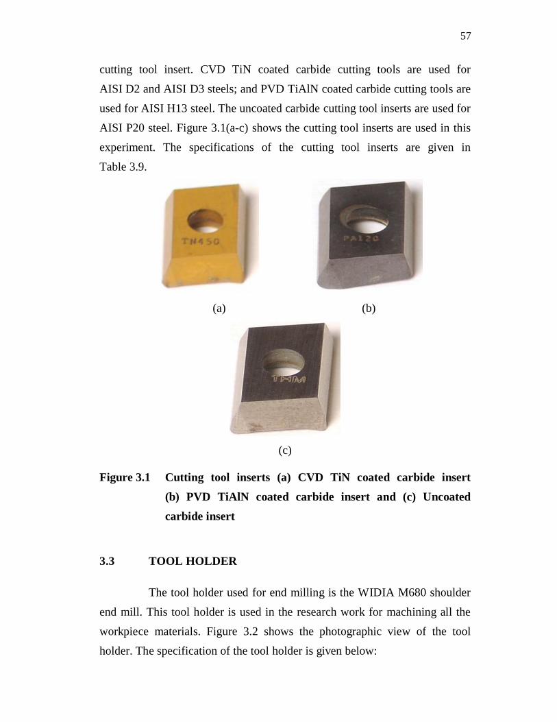
cutting tool insert. CVD TiN coated carbide cutting tools are used for
AISI D2 and AISI D3 steels; and PVD TiAlN coated carbide cutting tools are
used for AISI H13 steel. The uncoated carbide cutting tool inserts are used for
AISI P20 steel. Figure 3.1(a-c) shows the cutting tool inserts are used in this
experiment. The specifications of the cutting tool inserts are given in
Table 3.9.
(a) (b)
(c)
Figure 3.1 Cutting tool inserts (a) CVD TiN coated carbide insert(b) PVD TiAlN coated carbide insert and (c) Uncoatedcarbide insert
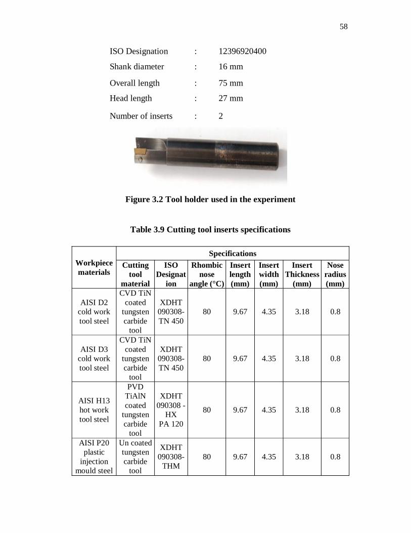
3.3 TOOL HOLDER
The tool holder used for end milling is the WIDIA M680 shoulder
end mill. This tool holder is used in the research work for machining all the
workpiece materials. Figure 3.2 shows the photographic view of the tool
holder. The specification of the tool holder is given below:
58
ISO Designation : 12396920400
Shank diameter : 16 mm
Overall length : 75 mm
Head length : 27 mm
Number of inserts : 2
Figure 3.2 Tool holder used in the experiment
Table 3.9 Cutting tool inserts specifications
Workpiecematerials
SpecificationsCutting
toolmaterial
ISODesignat
ion
Rhombicnose
angle (°C)
Insertlength(mm)
Insertwidth(mm)
InsertThickness
(mm)
Noseradius(mm)
AISI D2cold worktool steel
CVD TiNcoated
tungstencarbide
tool
XDHT090308-TN 450
80 9.67 4.35 3.18 0.8
AISI D3cold worktool steel
CVD TiNcoated
tungstencarbide
tool
XDHT090308-TN 450
80 9.67 4.35 3.18 0.8
AISI H13hot worktool steel
PVDTiAlNcoated
tungstencarbide
tool
XDHT090308 -
HXPA 120
80 9.67 4.35 3.18 0.8
AISI P20plastic
injectionmould steel
Un coatedtungstencarbide
tool
XDHT090308-
THM80 9.67 4.35 3.18 0.8

59
3.4 EXPERIMENTAL CONDITIONS
End milling experiments were carried out on the AISI D2, AISI D3,
AISI H13 and AISI P20 steels, using various tungsten carbide cutting tool
inserts at different speed-feed combinations under dry, wet and cryogenic
machining conditions. The experimental cutting conditions used in the milling
of the AISI D2, AISI D3, AISI H13 and AISI P20 steels are given in
Table 3.10.
Table 3.10 Experimental cutting conditions in the milling of the
AISI D2, AISI D3, AISI H13 and AISI P20 steels
Workpiecematerials
Cutting parameters
Cuttingvelocity(m/min)
Feed rate(mm/tooth)
Depth ofcut (mm)
Cooling methods
AISI D2 coldwork tool steel
75, 100 and125
0.01, 0.015and 0.02
0.5
(i) Dry
(ii) Wet
(iii) LN2 cooling
AISI D3 coldwork tool steel
75, 100 and125
0.01, 0.015and 0.02
0.5
(i) Dry
(ii) Wet
(iii) LN2 cooling
AISI H13 hotwork tool steel
75, 100 and125
0.01, 0.015and 0.02
0.5
(i) Dry
(ii) Wet
(iii) LN2 cooling
AISI P20 plasticinjection mould
steel
75, 100 and125
0.01, 0.015and 0.02
0.5
(i) Dry
(ii) Wet
(iii) LN2 cooling

60
3.5 EQUIPMENTS FOR THE EXPERIMENT
3.5.1 CNC Vertical Machining Centre
End milling experiments were carried out on an ARIX VMC 100
CNC machining centre. The machine specifications are shown in Table 3.11.
Table 3.11 Specifications of the ARIX VMC 100 CNC machining Centre
Description Technical Data1) Working Range
Longitudinal axis (X axis)Cross axis (Y axis)Vertical axis (Z axis)
1000 mm500 mm500 mm
2) Work spindlesTool MountingCentre to table
ISO 4010-450 mm
3) Spindle speed and feed ratesWork spindle speed, directlyprogrammableFeed rates directly programmablealong X, Y and Z axesRapid traverse a long X, Y and Z axes
60 – 5000 rpm
4000 mm/min
4000 mm/min
4) Electrical EquipmentVoltageX,Y,Z servo motorsSpindle motor
220 / 380 V750 W5HP
5) Weights and Space requirementsWeight of machine (including verticalmilling head, circular table, toolchanger, cabin and switch cabinet)Machine dimensionLengthWidthHeight
2700 kg
2700 mm2500mm2300 mm
61
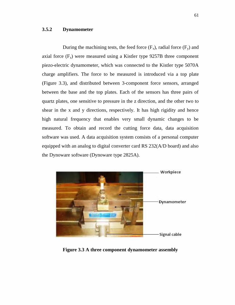
3.5.2 Dynamometer
During the machining tests, the feed force (Fx), radial force (Fy) and
axial force (Fz) were measured using a Kistler type 9257B three component
piezo-electric dynamometer, which was connected to the Kistler type 5070A
charge amplifiers. The force to be measured is introduced via a top plate
(Figure 3.3), and distributed between 3-component force sensors, arranged
between the base and the top plates. Each of the sensors has three pairs of
quartz plates, one sensitive to pressure in the z direction, and the other two to
shear in the x and y directions, respectively. It has high rigidity and hence
high natural frequency that enables very small dynamic changes to be
measured. To obtain and record the cutting force data, data acquisition
software was used. A data acquisition system consists of a personal computer
equipped with an analog to digital converter card RS 232(A/D board) and also
the Dynoware software (Dynoware type 2825A).
Figure 3.3 A three component dynamometer assembly

62
3.5.3 Infrared Pyrometer
The cutting temperature is measured in the tool – chip interfaces, in
different cutting environments, using a non-contact type Infrared pyrometer
(accuracy ±1.0°C), which can measure a temperature range of -50°C to
+1000°C. The cutting temperature is measured by making the Infrared ray
from the Infrared pyrometer to impinge exactly on the tool – chip interfaces
during the machining process, and the maximum temperature attained is
recorded. The Infrared pyrometer is calibrated for its measurement.
3.5.4 Surface Roughness Tester
The surface roughness after end milling was measured, using a
Taylor- Hobson Surtronic 3+ surface roughness tester. This surface roughness
tester combines advanced technology with high precision and its use for the
efficient measurement of the surface finish in the inspection room or
laboratory. The instrument can be handheld on horizontal, vertical and
inclined surfaces, or bench mounted with accessories for batch measurement
or laboratory applications. The pick-up holder is mounted on a slide for
vertical adjustment, and can also be rotated to different measuring positions,
including a right-angled measurement. The surface roughness was measured
at three locations on the machined workpiece. The value of the surface
roughness is the average of the three points taken for each measurement.
Table 3.12 shows the equipment specification.
Table 3.12 Specification of the Taylor-Hobson Surface Roughness tester
Model Surtronic 3+Manufacture UK
Cut-off length 0.25mm, 0.8mm and 2.5mmAccuracy 0.01 m
63
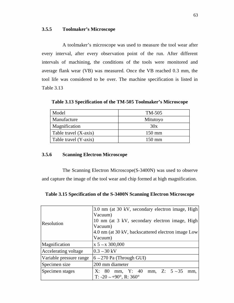
3.5.5 Toolmaker’s Microscope
A toolmaker’s microscope was used to measure the tool wear after
every interval, after every observation point of the run. After different
intervals of machining, the conditions of the tools were monitored and
average flank wear (VB) was measured. Once the VB reached 0.3 mm, the
tool life was considered to be over. The machine specification is listed in
Table 3.13
Table 3.13 Specification of the TM-505 Toolmaker’s Microscope
Model TM-505Manufacture MitutoyoMagnification 30xTable travel (X-axis) 150 mmTable travel (Y-axis) 150 mm
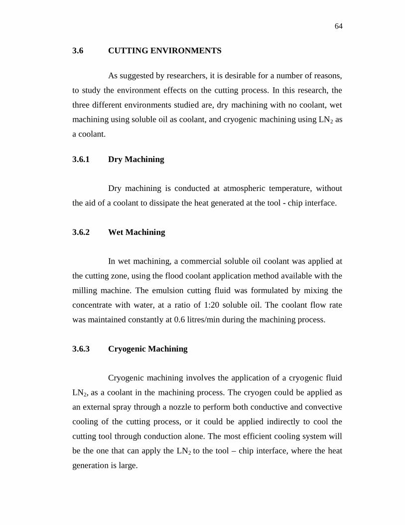
3.5.6 Scanning Electron Microscope
The Scanning Electron Microscope(S-3400N) was used to observe
and capture the image of the tool wear and chip formed at high magnification.
Table 3.15 Specification of the S-3400N Scanning Electron Microscope
Resolution
3.0 nm (at 30 kV, secondary electron image, HighVacuum)10 nm (at 3 kV, secondary electron image, HighVacuum)4.0 nm (at 30 kV, backscattered electron image LowVacuum)
Magnification x 5 x 300,000Accelerating voltage 0.3 30 kVVariable pressure range 6 270 Pa (Through GUI)Specimen size 200 mm diameterSpecimen stages X: 80 mm, Y: 40 mm, Z: 5 35 mm,
T: -20 +90°, R: 360°
64
3.6 CUTTING ENVIRONMENTS
As suggested by researchers, it is desirable for a number of reasons,
to study the environment effects on the cutting process. In this research, the
three different environments studied are, dry machining with no coolant, wet
machining using soluble oil as coolant, and cryogenic machining using LN2 as
a coolant.
3.6.1 Dry Machining
Dry machining is conducted at atmospheric temperature, without
the aid of a coolant to dissipate the heat generated at the tool - chip interface.
3.6.2 Wet Machining
In wet machining, a commercial soluble oil coolant was applied at
the cutting zone, using the flood coolant application method available with the
milling machine. The emulsion cutting fluid was formulated by mixing the
concentrate with water, at a ratio of 1:20 soluble oil. The coolant flow rate
was maintained constantly at 0.6 litres/min during the machining process.
3.6.3 Cryogenic Machining
Cryogenic machining involves the application of a cryogenic fluid
LN2, as a coolant in the machining process. The cryogen could be applied as
an external spray through a nozzle to perform both conductive and convective
cooling of the cutting process, or it could be applied indirectly to cool the
cutting tool through conduction alone. The most efficient cooling system will
be the one that can apply the LN2 to the tool – chip interface, where the heat
generation is large.
65
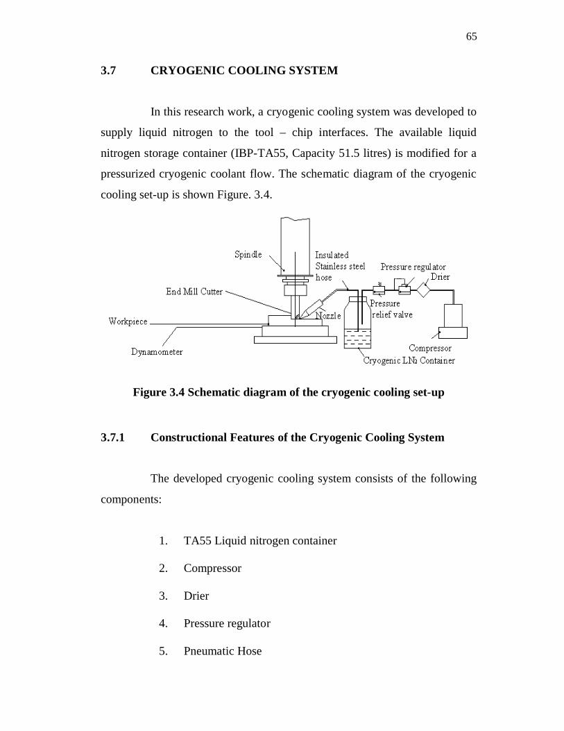
3.7 CRYOGENIC COOLING SYSTEM
In this research work, a cryogenic cooling system was developed to
supply liquid nitrogen to the tool – chip interfaces. The available liquid
nitrogen storage container (IBP-TA55, Capacity 51.5 litres) is modified for a
pressurized cryogenic coolant flow. The schematic diagram of the cryogenic
cooling set-up is shown Figure. 3.4.
Figure 3.4 Schematic diagram of the cryogenic cooling set-up
3.7.1 Constructional Features of the Cryogenic Cooling System
The developed cryogenic cooling system consists of the following
components:
1. TA55 Liquid nitrogen container
2. Compressor
3. Drier
4. Pressure regulator
5. Pneumatic Hose
66
6. Stainless steel pipes
7. Pressure relief valve
8. Braided Stainless steel hose
9. Nozzle
In this cryogenic cooling system, the TA55 liquid nitrogen
container of 51.5 litres capacity is used. It is made of aluminium, and the
walls of the container are completely sealed, so that the atmospheric
temperature does not affect the fluid inside the container. The container is
closed with a stainless steel cap at the top. Inlet (Ø 6 mm) and outlet
(Ø 4 mm) pipes are inserted in to the container through the cap, which is
made of stainless steel. These pipes are used for taking the compressed air
into the container and transferring the fluid to the cutting zone.
A compressor is placed before the container, which is used to
compress the air to the required pressure. A drier is placed after the
compressor, which removes the moisture from the compressed air before
entering the LN2 container. This will avoid water contamination inside the
container. A pressure relief valve is attached at the inlet pipe by means of a
“T” Joint. A flexible Braided Type stainless steel hose made of very low
thermal conductivity is attached to the nozzle at one end and the stainless
steel pipe at the other end, in order to supply the liquid nitrogen. The hose is
thermally insulated with polymer foam, in order to prevent the fluid being
affected by external heat during the transfer. The nozzle is used to direct the
LN2 at the tool – chip interface. The modified TA55 liquid nitrogen container
cap is shown in Figures 3.5 and 3.6, respectively.

67
Figure 3.5Cryogenic container cap
Figure 3.6 Modified TA55 cryogenic container
3.7.2 Working Principle of the Developed Cryogenic Cooling System
Liquid nitrogen is stored in the cryogenic container (IBP-TA55,
Capacity 51.5 litres). The compressed is supplied by an external compressor
air at a 3 bar pressure. To maintain the consistency of the compressed air
pressure during an experiment, the pressure regulator was used. The
compressed air was dried using a drain filter and passes to the cryogenic
container through an inlet pipe. This compressed air starts to force the fluid
down. The outlet pipe is placed at the bottom of the container. Due to the air
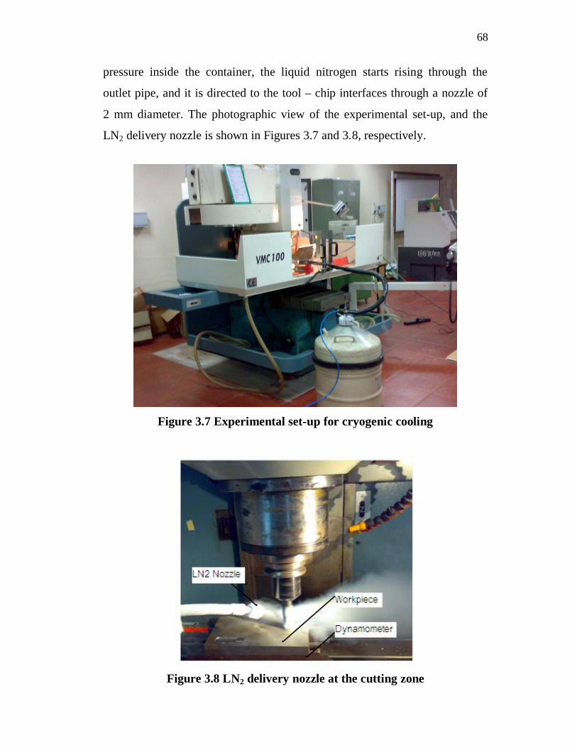
68
pressure inside the container, the liquid nitrogen starts rising through the
outlet pipe, and it is directed to the tool – chip interfaces through a nozzle of
2 mm diameter. The photographic view of the experimental set-up, and the
LN2 delivery nozzle is shown in Figures 3.7 and 3.8, respectively.
Figure 3.7 Experimental set-up for cryogenic cooling
Figure 3.8 LN2 delivery nozzle at the cutting zone