chapter 3 hydrology and sediment transport · chapter 3 hydrology and sediment transport ... 28...
TRANSCRIPT

Chapter 3 – Hydrology and sediment transport 27
Chapter 3
Hydrology and sediment transport
SUMMARYIn developing a spate system it is important to understand the entire hydrology of the system – the base flow, sub-surface flow and groundwater and the pattern of spate floods that will dictate the potential yield of spate systems, the design of diversion structures and canals and the area to be potentially irrigated.
Spate hydrology is characterized by a great variation in the size and frequency of floods, which directly influence the availability of water for agriculture in any one season. Spate floods can have very high peak discharges and are usually generated in wadi catchments by localized storm rainfall. Crop production varies considerably because of the large variation in wadi runoff from year to year, season to season and day to day. The extreme characteristics of wadi hydrology make it very difficult to determine the volumes of water that will be diverted to fields and hence the potential cropped areas.
Wadis transport very high sediment loads which can be two or more orders of magnitude larger than those encountered in most runoff river perennial irrigation systems. Management of sedimentation is, therefore, a key factor in spate irrigation and must be given particular consideration in designing spate projects.
Hydrological and sediment transport data are needed to design improved water diversion structures and canals in spate schemes and to estimate the cropped area that can be potentially reached by spate. These data include the annual volumes of water available at the diversion point(s); the probable distribution of spate runoff events; the distribution of flows during runoff events; the proportion of the annual hydrograph that occurs in different flow ranges; wadi bed seepage rates; the magnitude and return periods of extreme discharges for the design and protection of the permanent works; the concentrations and size range of the sediments transported by spate events and their relationship with wadi discharges; and the sediment-transporting capacity of existing canals.
In particular, the distribution of discharges within the annual runoff has a large impact on the water diversion strategy that will be adopted, particularly with regard to the relative importance of seasonal base flows.
In most schemes, the long-term data that would be needed to provide the information listed above is unavailable. Unless a period of hydrological and sediment data collection, combined with numerical flow and sediment transport models is possible, the estimation of the above variables must be made through the use of empirical methods combined with good hydrological judgement. Table 3.1 lists some of the methods used to collect and analyse the hydrological and sediment transport information required to design improved intakes and canal networks. They are described in the following sections.

Guidelines on spate irrigation28
The calculation of mean annual runoff through a simple runoff coefficient, combined with the use of non-dimensional flow duration curves, makes it possible to estimate the volumes of water that can be diverted and design spate intakes accordingly. Such curves and coefficient depend on the characteristics of the catchments and local climate and care must be taken in applying them to ungauged catchments.
Local knowledge can greatly contribute to the assessment of hydrological characteristics of wadi catchments and is often the only source of information. Farmers in the wadi can provide information on the number and sizes of floods and their variations between years, thus making it possible for the hydrologist to establish flood-frequency curves.
More important is the use of local knowledge for the establishment of potentially cropped areas. In areas where traditional spate irrigation exists, farmers can determine the area to be irrigated on the basis of their past experience and from observation of the quantities of water diverted by any improved diversion and conveyance arrangements. This involves surveys to determine the extent of the existing irrigated areas. Surveys have to be combined with local knowledge and supplemented by interviews with farmers to establish how often fields in different parts of the system are irrigated and how this varies from year to year.
When new areas are being developed, irrigation engineers and agronomists need to determine the potential area that can be irrigated and the capacities of the canals that will be needed through estimates of the proportion of annual runoff that will be diverted, its distribution in time, and the characteristics of the area to be cropped (including soil water-holding capacity). Crop water requirements, while they provide a useful estimate of the maximum volumes of water required, will usually not be the main factor in assessing the potential irrigated area, as farmers will seek to expand their land under irrigation to the maximum possible extent.
Another important characteristic of wadi hydrology is the high rate of infiltration of floodwater in the wadi bed, with many small floods not reaching the lower reaches of the wadi. Seepage in the wadi bed is often the only source of groundwater recharge. Consequently, what is often considered ‘loss’ for spate through seepage may very well be used in a very productive way through groundwater extraction. Similarly, when spate intakes divert a substantial part of the wadi flow, they impact groundwater recharge downstream with possible negative implications for communities relying on groundwater. A river basin approach to spate irrigation planning is therefore necessary, to ensure that any intervention results in an overall increase in benefits for the populations of the wadi, and avoids losses for water users downstream (see Chapter 10).
Chapter 3 – Hydrology and sediment transport 29
INTRODUCTIONSpate hydrology is characterized by a great variation in the size and frequency of floods which directly influence the availability of water for agriculture. Wadis are also characterized by very high sediment loads and important groundwater recharge through seepage in the wadi bed. All these characteristics are specific to wadi hydrology. Management of floods and high sediment load therefore require a good estimate of the main hydrological characteristics of the wadi.
This chapter presents a brief description of runoff and sediment transport processes that influence spate irrigation practices and the design of improved spate irrigation schemes. It also provides some simple methods that can be used to derive the hydrological information needed to design intakes and canals for spate irrigation systems. The emphasis is on methods used for small schemes, where little data are available and the specialist hydrological studies that are carried out in support of larger projects are not feasible. The results derived with these methods should be verified wherever possible by comparison with any local or regional data that may be available.
DATA REQUIREMENTSHydrological and sediment transport data are needed to design improved water diversion structures and canals in spate schemes. The following information should ideally be available to designers of intakes and canals:
� the annual volumes of water available at the diversion point(s) in terms of seasonal incidence and reliability;
� the probable distribution of spate runoff events in terms of peak flows and flood volumes;
� the distribution of flows during runoff events, particularly the shape of the recession limb of the hydrograph, which provides the bulk of the water that can be diverted to irrigation command areas;
� the proportion of the annual hydrograph that occurs in different flow ranges (flow duration curve);
� wadi bed seepage rates; � the magnitude and return periods of extreme discharges for the design and protection of the permanent works;
� the concentrations and size range of the sediments transported by spate events and their relationship with wadi discharges; and
� the sediment-transporting capacity of existing canals.
In most schemes, the long-term data needed to provide the information listed above are unavailable. Major spate irrigation improvement projects thus include a short period of hydrological and sediment data collection. The data are often used to assist in validating numerical flow and sediment transport models.
For small- and medium-scale schemes data requirements are smaller, and simpler methods requiring minimal field data are appropriate. Maximum use needs to be made of the local knowledge that farmers have. Table 3.1 lists some of the methods used to collect and analyse the hydrological and sediment transport information required to design improved intakes and canal networks. They are described in the following sections.
WADI HYDROLOGY AND IMPLICATION FOR SPATE DESIGNThe high-intensity rainfall events that generate spate flows in wadis are characterized by a wide variability in space and time. Information on the spatial characteristics of

Guidelines on spate irrigation30
TABLE 3.1Hydrological and sediment transport information collection methods
Parameter Method Remarks
Seasonal/annual discharge and probabilities of occurrence
Long-term discharge data from flow-gauging station
Rarely if ever available.
Needs properly sited and maintained gauging station.
Discharge usually computed from continuous water level records and derived rating curve(s).
Velocity measurement in floods is extremely difficult, although surface float tracking is feasible.
Numerical models verified/calibrated by short-term discharge data
Usually only feasible for major studies.
Needs good-quality, long-term rainfall data from catchment.
Some gauging station data desirable for validation.
Short-term discharge data supplemented by farmers’ recollections of numbers of floods occurring and areas irrigated in past years
Annual and monthly runoff is broadly correlated with the number of floods that occur.
Irrigated areas usually vary widely from year to year, reflecting discharge variations.
Regional rainfall/runoff relationships/empirical methods supplemented by farmers’ recollections
Method needs to be selected and interpreted by experienced hydrologist.
Design’ extreme flood discharges
Analysis of long-term records of annual flood maximum discharges
Data rarely available.
Synthetic long-term runoff data derived from stochastic modelling
Usually only feasible for major studies.
‘Rational’ methods Need rainfall intensity and other parameters derived from catchment characteristics.
Need verification with measured or slope area estimates of flood maxima.
Regional flood frequency relationships
Often the most reliable method as based on large number of station years of measurement.
Need to estimate the mean annual maximum flood in order to use reported growth factors.
Slope area calculations Used to estimate peak discharge of historical floods by means of local informants’ estimates of the flood water level.
Discharge capacity of exiting canals
Current metering in floods Difficult, need to be on site when large floods occur (often at night), requires heavy equipment.
Slope area calculations Ideally gauge boards/automatic water installed to provide reliable water-level records.
Farmers may provide estimates of water levels when canals have been breached/overtopped.
Sediment transport Bed material sediment sizes, wadi bed and canals
Large samples needed when coarse wadi bed material is to be size graded.
Stone-counting methods available for cobble and boulder shoals.
Pump sampling during floods at discharge-gauging location
Needs continuous presence on site unless automatic sampling equipment is used.
Measures suspended load component only; bed load is usually derived from empirical relationships.
Needs concurrent measurement of discharges plus size-grading data of bed material.
Dip samples collected in bottles during floods
Measures wash load, useful for estimating fine sediment concentrations passed to fields.
Can be supplemented with sediment transport predictors to estimate sand and bed load.
Need concurrent measurement or estimates of discharges and size-grading data of bed material.
Historical rates of rise of field levels and command levels
Surveys of field levels, trial pits, upstream movement of traditional diversion structures.

Chapter 3 – Hydrology and sediment transport 31
rainfall wadi catchments is limited. Available data, however, suggest a highly localized rainfall occurrence, with the spatial correlation approaching close to zero at distances of between 15 and 20 km (IHP, 1996).
Wadi catchments generally have sparse vegetation cover and thin rocky soils. Soils are exposed to raindrop impact and soil crusting, which results in low infiltration capacity. Storm rainfall generates local overland flow, which converges into wadi channel networks, producing spate runoff events. Runoff generation is usually localized, reflecting the small size of convective rainfall cells. There is some evidence, however, that extreme flood events are sometimes generated by more widespread frontal rainfall, as has been observed in the catchment of Wadi Zabid in Yemen.
Rainfall-runoff relationship The local nature of rainfall events presents difficulties when attempts are made to link flood events with storm rainfall observed at rain gauges located at the densities found even in relatively well equipped catchments. This is illustrated in the example shown in Box 3.1, which demonstrates the very poor correlation between observed rainfall and runoff that can be expected (Wheater, 1996). Similar conclusions were drawn from a recent study in the catchments of large spate irrigation systems in the Yemen (Arcardis, 2004) and a study carried out in Eritrea (Halcrow, 1997). Estimates of flood discharges and runoff volumes derived from conventional rainfall/runoff models are therefore of limited use in spate systems (IHP, 1996).
BOX 3.1
Rainfall-runoff relationship in semi-arid catchments
A comparison of measured flood runoff depths with rainfall derived from five rain gauges located in a 597 km2 catchment in western Saudi Arabia is shown below (Wheater, 2002). The plot shows no correlation between runoff measured at the catchment outlet and rainfall events observed with the rain gauge network, which have a density of around one per 120 km2, and the storm with the largest runoff appears to be generated by the smallest rainfall.
0
0.5
1
1.5
2
Tota
l ru
no
ff (
mm
)
Total rainfall (mm)
2.5
3
0 5 10 15 20 25

Guidelines on spate irrigation32
Analysis of discharge data from wadis in Yemen shows an approximate linear correlation between both annual and monthly flood volumes and the number of floods that occur, if a few rare extreme floods are excluded. Similar features were observed in the results from stochastic modelling of spate runoff carried out for Wadi Laba in Eritrea (Halcrow, 1997). This conclusion is very useful as it enables annual flow volumes to be linked, albeit approximately, with the numbers of floods that occur, which will be known by farmers.
Shape of the spate hydrographFlows move down the channel network as a flood wave. Runoff from different parts of a catchment converges in the steep wadi channels, sometimes generating multi-peaked spate flows at the water diversion sites in the lower wadi reaches. Flood hydrographs are characterized by an extremely rapid rise in time, followed by a short recession, as illustrated in Figure 3.1. In this case, the discharge at a spate diversion site in Wadi Rima in Yemen increased from less than 1.0 m³/s to about 550 m³/s in around 30 minutes, with a second smaller peak occurring the next day. The lower water surface elevation after the flood is due to bed scour.
FIGURE 3.1Spate flood hydrograph from Mishrafah, Wadi Rima, Yemen, 1981
18:00
0
0.5
1
1.5
2
2.5
3
3.5
4
4.5
13 March 1981
Leve
ls (
m)
14 March 1981 15 March 1981
6:00 18:00 6:00 18:00 6:00 18:00 6:00

Chapter 3 – Hydrology and sediment transport 33
Attempts have been made to establish relationships between flood peak discharges, flood durations and flood volumes. Recent studies in Yemen and Eritrea, however, show little or no correlation between peak discharges and flood volumes (Halcrow, 1997; Arcardis, 2004). Floods with a small peak discharge can have a long duration and a large flood volume, while conversely floods with a large peak discharge can have a very short recession and a small flood volume. Floods generated at distant parts of catchments are attenuated by the time they reach a diversion site, and the relationship between flood characteristics depends to some extent on where in catchments the flood-producing rainfall occurred.
As with other hydrological parameters, the distribution of flood peak discharges occurring in wadis is highly skewed. Relatively few large floods occur, and most of the annual flood runoff volume occurs in floods having low or medium flood peak discharges. In some wadis, flood flows are supplemented by spring-fed base flows that may persist for some weeks or months through and after the wet season. Subsurface flows in underlying alluvium may be forced to the surface by a rock bar and appear as a surface flow part way down a dry wadi bed.
The relative proportion of base flows and flood flows in the annual hydrograph has a large impact on the water diversion strategy to be adopted. This is illustrated in Box 3.2, which shows contrasting discharge statistics for wadis flowing to coastal plains located on either side of the Red Sea.
Where most of the annual discharge in wadis occurs at low to medium flow rates, high diversion efficiencies can be obtained by diverting relatively low wadi discharges through the use of simple diversion structures. This is one reason why high diversion efficiencies are obtained in many traditional spate irrigation systems, even though some upstream intakes are regularly washed out in floods.
Over-reliance on diversion of base and low flood flows at a single intake, a strategy adopted in some spate irrigation improvement projects, can be dangerous. In Yemen, it is reported that water abstractions upstream from some diversion sites have substantially increased and the base flows have been reduced or cutoff. In most cases where a new single intake has been constructed as part of a modernization project, farmers have retained their traditional diversions, and in some cases have constructed new ones to capture the flood flows passing a new diversion weir, so as to divert the largest possible proportion of wadi flow to compensate for the limited diversion capacity of the new intake.
Seepage in wadi bed and groundwater recharge Both channel storage and high infiltration rates into the coarse alluvium that forms the beds of wadis reduce discharges as floods pass down a wadi. Water balance studies carried out for the Tihama coastal plain bordering the Red Sea in Yemen indicate that around 60 percent of groundwater recharge is derived from wadi flows (DHV, 1988). Komex (2002) reported that infiltration of wadi flows provides the major source of recharge to the aquifers of both the Abyan and Tuban deltas in Yemen. Apart from a quantity of subsurface inflow, wadi flows provide the only source of replenishment for the aquifers. Other recharge components are merely infiltration of diverted spate flows or recycling of abstracted groundwater. A water balance study carried out for Wadi Turban indicated that approximately 48 percent of the surface inflow recharged the aquifer by infiltrating from wadi beds (Komex, 2002). Infiltration from spate irrigation increased the recharge by only a further 10 percent.

Guidelines on spate irrigation34
Estimates of seepage (transmission) losses in wadis have been made using simultaneous flow measurements at different locations. Losses, mostly measured for very low flows, typically range between 1 and 5 percent of the upstream discharge per km (Lawrence, 1986; Walters, 1990; Jordan, 1977). Studies carried out in Yemen in the 1970sv suggest that seepage rates in seasoned traditional canals were much lower than that in the main wadi channels (Makin, 1977). If maximum use is to be made of spate flows, there may thus be advantages in using canals rather than the main wadi channel to convey irrigation flows to the downstream areas of a scheme. However, the use of shallow groundwater for irrigation is increasing in many spate areas and, where this is the case, it can be argued that seepage losses should be enhanced rather than minimized, in order to maximize groundwater recharge.
BOX 3.2
Contrasting wadi discharge statistics
The graph shows the percent of the annual runoff volume occurring in different discharge ranges for Wadi Rima in Yemen, and Wadi Laba in Eritrea, from the data reported in Makin (1977) and from stochastic modelling carried out by Halcrow (1997).
In Wadi Rima, as in the other large Tihama wadis, spring-fed base flows and low flows occurring at the end of flood recessions provide a large proportion of the annual flow volume. In Wadi Rima, at the time that the measurements were carried out, diverting all the water flowing in the wadi at discharges of less than 15 m³/s was predicted to divert about 90 percent of the annual discharge. The intake discharge capacity of 15 m3/s in this case represented only about 3 percent of the anticipated annual return flood peak discharge in this wadi.
Wadi Laba has a catchment area about four times smaller than Wadi Rima, and has a much lower annual flood peak discharge. As most of the annual runoff is predicted to occur in spate flows, a relatively larger diversion capacity was adopted in order to divert an acceptable proportion of the annual runoff. An intake capacity of 35 m3/s was selected, 23 percent of the estimated annual return flood peak discharge of 150 m3/s.
0
10
20
30
40
50
60
<2 2-5 5-10
Discharge range (m3/s)
10-20 20-50 >50
Wadi Rima
Perc
enta
ge
shar
e o
f d
isch
arg
e ra
ng
es
Wadi Laba

Chapter 3 – Hydrology and sediment transport 35
One important consequence of the role of seepage in groundwater recharge is the need for a river basin approach to spate irrigation design. What is considered ‘loss’ for spate irrigation through seepage in the wadi bed may well be used in a very productive way through groundwater extraction. Similarly, when spate intakes divert a substantial part of the wadi flow, they impact groundwater recharge downstream, with possible negative implications for communities relying on groundwater. These considerations are discussed in greater detail in Chapter 10.
ESTIMATING MEAN ANNUAL RUNOFF AND POTENTIAL IRRIGATED AREAThe proportion of the mean annual runoff (MAR) that can be diverted to the fields is an important parameter in determining the potential command area, although in spate schemes the areas that are irrigated can vary widely from year to year. MAR is conventionally expressed as a runoff depth from the catchment, in mm, but can easily be converted to a volume by multiplying it by the catchment area. The proportion of the runoff volume that can be diverted for irrigation depends on the diversion arrangements and the patterns of spate flows that are experienced. This is difficult to estimate without extensive long-term site-specific flow data.
In spate schemes the cropped areas are determined in part by the level of risk that farmers are prepared to accept before constructing and maintaining canals and field bunds and preparing their fields. While the fields near the head of a scheme may receive multiple irrigations, those near the tail may only receive water occasionally. In some spate schemes in Yemen, irrigation is reported to be possible as infrequently as once in five years at the downstream end of the irrigated areas. Farmers also adopt differing irrigation strategies. A few attempt to maximize yields by applying multiple irrigations to small areas, while others more commonly spread the water as widely as possible and often grow a crop from a single large water application. Both strategies may be followed at different locations within the same scheme. The relationship between the flows in a wadi in particular seasons and the areas that are irrigated can thus be quite complex and require a large investment in field investigations and farmer interviews if it is to be fully understood.
The operation and management of most systems is carried out entirely by farmers, as well as the decisions concerning patterns of water distribution and the areas that have priority for irrigation. The calculations described in this section are normally not needed, as farmers will determine the area to be irrigated on the basis of their past experience and from observation of the quantities of water diverted by any improved diversion and conveyance arrangements. However, when new areas are being developed, irrigation engineers and agronomists need to determine the potential area that can be irrigated and the capacities of the canals that will be needed. Estimates of the mean annual runoff and the proportion of the runoff that will be diverted need to be made in order to carry out these calculations. Similar calculations are carried out when large existing systems are to be modernized.
Using farmers’ knowledge If estimates of cropped areas are needed when existing schemes are being improved, the most reliable procedure is to base assessments on existing cropped areas. This will involve surveys and analysis of aerial photographs, when available, to determine the extent of the existing irrigated areas. Surveys are supplemented by interviews with farmers to establish how often fields in different parts of the system are irrigated and how this varies between years.

Guidelines on spate irrigation36
Farmers can also provide information on the numbers and sizes of floods and their variations between years. If surveys of the main canal(s) have been carried out, then slope area calculations described later can be used to convert farmers’ estimates of water levels and the periods that canals flow, to make an approximate estimate of the volumes of water diverted from flood events.
Estimates of the impact of improved diversion arrangements can then be based on the additional volumes of water that might be supplied to the fields with improved diversion and conveyance arrangements. However, as many traditional spate irrigation systems are already operating with high water-diversion efficiency, there may not be much scope to increase irrigated areas. The main benefits from spate improvement projects usually stem from a reduction in the large labour requirements needed to operate and maintain the traditional intakes and canals.
Estimating mean annual runoff using a runoff coefficient The simplest method of estimating mean annual runoff is to apply a runoff coefficient to the mean annual rainfall over the catchment:
MAR = k . MAP
where:
MAR = mean annual runoff (mm) MAP = mean annual precipitation (mm) k = runoff coefficient
Runoff coefficients for catchments of wadis typically range between 0.05 for larger catchments and 0.10 for smaller catchments. However, runoff coefficients can vary considerably, even between adjacent catchments and, if this approach is used, then a hydrologist with knowledge of the local catchments should select an appropriate runoff coefficient. More sophisticated methods for estimating mean annual runoff are available, but these need to be applied by experienced hydrologists, preferably with a good knowledge of local conditions.
Calculation of runoff volumes The annual volume of runoff from a catchment is calculated as the product of the MAR and the catchment area. Catchment areas should be measured on 1: 50 000 maps, after marking the intake location(s) and the catchment boundaries, by using a digitizer, planimeter or squared overlay sheet.
ARV = MAR . A . 1 000
where:
ARV = annual runoff volume (m3) MAR = mean annual runoff (mm) A = catchment area (km2)
Estimating the proportion of annual runoff that is diverted As mentioned earlier, the proportion of the MAR that is diverted depends on the diversion arrangements and the pattern of flows that occur and is very difficult to estimate without long-term flow data collected at or near to the diversion site. Very few measurements have been carried out in spate schemes, but information from

Chapter 3 – Hydrology and sediment transport 37
traditional systems in Yemen suggests that high diversion efficiencies were achieved when numerous intakes were used. Although large floods destroy upstream deflectors, water could usually be diverted downstream where the flood peaks had diminished. Only rarely did exceptionally large floods pass the last diversion structure.
For new schemes with a single diversion point, approximate estimates of the proportions of flows diverted for a range of intake capacities can be derived from non-dimensional flow duration curves when these are available or can be developed from regional hydrological data. An example for two spate rivers in Eritrea is shown in Figure 3.2. In this form of the duration curve the number of hours a wadi flows in different discharge ranges is plotted against the wadi discharge representing the discharge range. The curves are made non-dimensional by dividing discharges by the mean annual flood discharge (Q) and times by the total time that a wadi flows in the year (T). In the absence of more specific local information, non-dimensional flow duration curves developed for one catchment may be transferred to another catchment of similar size in the same region if they are in similar rainfall zones and it can be assumed that the relative distribution of discharges within an annual runoff hydrograph will be similar.
Curves like those shown in Figure 3.2 can be used to estimate of the proportion of the annual flows that would be diverted from a wadi for different ratios of q/Q, where q is the selected intake capacity. The calculation assumes that all the flows less than the
FIGURE 3.2Non-dimensional flow duration curve
0
0 0.1 0.2 0.3 0.4 0.5
q/Q
0.6 0.7 0.8 0.9 1
R Gash
t/T
Wadi Laba Regression line
0.1
0.2
0.3
0.4
0.5
0.6
0.7
0.8
0.9
1

Guidelines on spate irrigation38
q/Q will be diverted and that diversion will be at the intake capacity q/Q when wadi discharges are higher than the diversion capacity. Diversion efficiencies calculated using these assumptions with the mean curve shown in Figure 3.2 are presented in Table 3.2. The table illustrates the predominance of lower flows in the annual runoff in spate rivers, that in this case do not include significant periods of seasonal base flow. More than half the annual discharge could be diverted with a canal intake capacity set at 10 percent of the mean annual flood discharge, while an intake with the capacity to divert 50 percent of the mean annual flood discharge would divert 96 percent of the annual runoff. Of course reductions to the theoretical diversion efficiency tabulated above are needed to account for the real situation, where canal and sluice gates at an intake have to be manually operated, often at night, in response to rapidly varying spate flows.
If the regional data needed to prepare a non-dimensional flow duration relationship are not available, approximate estimates of the proportion of the wadi flows diverted to canals can be derived by using farmers’ knowledge of the number and sizes of floods and the shape and duration of typical flood recessions. The procedure involves assembling a representative sequence of flood hydrographs and determining the proportion of the wadi flows that might be diverted for a range of intake capacities. If multiple intakes are to be used, bed seepage losses between the intake locations should also be taken into account.
It is also necessary to make an estimate of the likely variations between years. When data are not available, this can be achieved by assuming that the annual runoff volumes are approximately proportional to the numbers of floods that occur and using farmers’ estimates of flood numbers for years with different return periods.
When the flow volumes diverted during the cropping season have been established, the area that could be irrigated can in theory be estimated by calculating the crop water requirements and conveyance and irrigation efficiencies. However, as indicated above, other factors will influence the area that can be irrigated. Farmers have their own views on the command areas that they are prepared to develop and these may not coincide with areas derived from rather simplistic calculations relying on assumed crop water requirements and diversion and conveyance efficiencies. In existing schemes estimates of potential cropped areas should at least be verified by comparison with currently cropped areas.
DESIGN FLOOD DISCHARGEEstimates of extreme flood discharges for specified return periods are needed to design weirs and intakes. As spate floods are always characterized by a very rapid rising limb, they should not be represented using classic triangular hydrograph models which do
TABLE 3.2Proportion of annual flows diverted
Diversion capacity ratio q/Q Percent of annual flow diverted
0.1 54.3
0.2 76.8
0.3 86.6
0.4 92.2
0.5 95.6

Chapter 3 – Hydrology and sediment transport 39
not replicate well the rapid rise to peak, the rapid initial recession or the proportions of the flood volume occurring before and after the flood peak. Several methods can be used:
� analysis of long-term records of measured flood discharges; � analysis of synthetic long-term runoff data derived from stochastic modelling; � the rational methods based on a ‘design’ rainfall intensity, a time of concentration derived from catchment parameters and a runoff coefficient that depends on catchment conditions;
� regional flood frequency relationships; � slope area calculations to estimate the size of the largest historical flood that has occurred, for which local informants can provide a reasonably reliable estimate of the flood water level.
In practice, the first method is virtually never feasible as long-term flow data only exist for a small number of wadis worldwide. The second would only be considered for large projects that have the resources to commission specialized hydrological modelling. Rational methods are used in some areas, for example Balochistan, in Pakistan, but require information on catchment characteristics for the selection of appropriate runoff coefficients and rainfall intensity, data that are not available in the regions where many spate irrigation systems are located.
Regional flood frequency relationships are widely used for flood estimation in un-gauged catchments. They are derived by pooling data from gauged catchments within hydrologically similar regions, to develop a dimensionless flood frequency relationship that can be applied to un-gauged catchments in the same region.
Care has to be exercised when transferring data from one catchment to another. Catchment elevation, shape and geology all play a significant part in the estimation of runoff characteristics. One of the mistakes in Sheeb in Eritrea was to approximate the flow results obtained for Wadi Laba to the smaller and more compact catchment of Wadi Mai Ule.
The mean annual flood discharge for the wadi being considered has to be known in order to use the method, and empirical methods can also be applied to estimate this from catchment properties. Table 3.3 proposes some empirical formulae. They need to be considered with caution as they are usually valid only in specific regional conditions.
TABLE 3.3Methods for estimating mean annual flood peak discharge
Method Equation Note
Binnie (1988) MAF = 3.27 . A1.163 . MSL–0.935 Regional flood formula developed for wadis in Southern Yemen
Bullock (1993) MAF = 0.114 . A0.52 . MAP0.537 Developed using data from 43 semi-arid catchments in Botswana, Zimbabwe, South
Africa and Namibia
Nouh (1988) MAF = 0.322 . A0.56 . ELEV0.44 Developed from regressions on data from 26 gauging stations
Farquharson et al. (1992)
MAF = 0.172 . A0.57 . MAP0.42 Developed from 3 637 station years of data collected from arid zones worldwide.

Guidelines on spate irrigation40
In the table:
MAF = mean annual flood peak discharge (m3/s) A = catchment area (km2) ELEV = mean catchment elevation (m) MSL = main stream length (km) MAP = mean annual precipitation (mm)
Farquharson et al. (1992) also developed relationships for eight separate regions using catchment area only, as follows:
MAF = Constant . A Exponent
The following values for the constant and exponent and regression results are given in Table 3.4, where s is the standard error of the estimate of the exponent and r2 is the regression coefficient.
If relationships for the specific local region are unavailable the Farquharson et al. (1992) mean relationship listed in the table can be used to estimate MAF. However, as estimates derived by using any of these equations may have a high standard error, it is recommended that estimates of MAF are at least verified by using estimates of the discharges of historical floods. This is discussed later.
Many regional flood frequency relationships are available. We suggest using the Farquharson et al. (1992) relationships that were developed from a large dataset of runoff stations in arid and semi-arid zones worldwide. The design flood for the required return period is calculated by multiplying the MAF by a growth factor for the ‘design’ return period selected from Table 3.5.
INCORPORATING LOCAL INFORMATION IN THE ESTIMATION OF FLOOD PEAK DISCHARGEThe reliability of estimates of MAF can be improved by making use of flood discharges calculated from historical water levels at or close to the location of new or improved intakes. The procedure involves obtaining information locally on the maximum wadi water level that occurred in the largest remembered historical flood and the number of years that the flood level was not exceeded (sometimes taken as the period since
TABLE 3.4Regional values for constant and exponent and regression results (Farquharson et al., 1992)
Country or region Constant Exponent s r2
Algeria/Morocco/Tunisia 0.489 0.801 0.07 0.92
Botswana/South Africa 8.75 0.388 0.06 0.49
Iran 0.145 0.866 0.15 0.60
Jordan 6.83 0.427 0.53 0.14
Queensland 1.31 0.597 0.07 0.71
Saudi Arabia/Yemen 0.991 0.701 0.16 0.43
USA (SW) 0.286 0.761 0.12 0.87
Caucasus/Central Asia (SW) 0.236 0.758 0.16 0.89
All arid region basins 1.87 0.578 0.04 0.55

Chapter 3 – Hydrology and sediment transport 41
the historical event occurred). The flood water level is then used to derive an estimate of the peak discharge using a slope area calculation method (see next section). The approximate return period for the event can be estimated if it is assumed that the probability of a flood of the given magnitude occurring in n years is 0.5, when:
T = 1/(1-0.51/n)where:
T = Return period of the flood (years) n = number of years over which the flood level was not exceeded.
By using the growth factors for the appropriate return period from Table 3.6 the ratio between the flood magnitude at the estimated return period and the MAF and hence an estimate for MAF can be obtained. The estimate for the MAF is then used to determine the design flood discharge for the appropriate design return period.
As an example, we assume that there is an estimate of the discharge of a historical flood available from a slope area calculation based on local information on the maximum water level observed in the last nine years. The flood discharge calculated from a slope area calculation is 250 m3/s.
As the flood discharge was not exceeded for nine years, n = 9. From the above equation T = 13 years. From Table 3.6 the growth factor for 13 years is about 2.4. Hence, the MAF derived from the slope area flood discharge is:
MAF = 250/2.4 = 104 m3/s
The 100-year return period flood will therefore be 104 x 6.5 = 677 m3/s.
ESTIMATES OF FLOOD DISCHARGE FROM WATER LEVELSWhile information on runoff is often scarce or absent, fairly good estimates of water levels, sometimes dating back many years can be obtained from measurements or from consultation with local farmers. They can then be translated into runoff estimates and contribute to a better flood frequency analysis.
TABLE 3.5Flood growth factors
Country or region Growth factor Growth factor 50-year return period 100-year return period
Algeria/Morocco/Tunisia 4.30 5.83
Botswana/South Africa 4.70 6.51
Iran 3.70 4.81
Jordan 4.07 5.27
Queensland 4.82 6.53
Saudi Arabia/Yemen 4.84 6.66
USA (SW) 4.45 6.34
Caucasus/Central Asia (SW) 4.27 5.61
All arid and semi-arid regions (MAP < 600 mm) 4.51 6.15

Guidelines on spate irrigation42
The Manning equation is usually used to compute discharges from water level, cross- section(s), the water surface slope, (often assumed to be the same as the bed slope) and an estimated Manning roughness coefficient which depends on the wadi bed conditions. Calculations are carried out for a reasonably uniform and straight wadi reach, located close to the actual or proposed intake. Measurement sites should be selected using the following criteria:
� Local information is used to make a reliable estimate of the water levels observed during a historical flood at the site.
� The length of reach should be greater than, or equal to, 75 times the mean depth of flow.
� The fall of the water surface should exceed 0.15 m from one end of the reach to the other.
� The flow should be confined to one channel at the flood level with no flow bypassing the reach as over-bank flow.
� Application of the flow resistance equation requires that the bed should be largely free of vegetation and that the banks should not be covered by a major growth of trees and bushes. Sites with bedrock outcrops should also be avoided.
It is difficult to satisfy all the above criteria and some compromise is usually necessary. The selected reach is surveyed to establish at least one cross-section and the bed slope. (Usually three cross-sections, at the start, middle and end of the reach are surveyed.)
TABLE 3.6Flood growth factors for Botswana and South Africa (Farquharson et al., 1992)
Flood return period(years)
Growth factor Flood return period(years)
Growth factor
5.0 1.3 30.0 3.7
6.0 1.5 32.0 3.8
7.0 1.7 34.0 3.9
8.0 1.8 36.0 4.0
9.0 1.9 38.0 4.1
10.0 2.1 40.0 4.2
12.0 2.3 42.0 4.3
14.0 2.5 44.0 4.4
16.0 2.7 46.0 4.5
18.0 2.8 48.0 4.6
20.0 3.0 50.0 4.7
22.0 3.1 100.0 6.5
24.0 3.3 150.0 7.8
26.0 3.4 200.0 8.9
28.0 3.5 - -

Chapter 3 – Hydrology and sediment transport 43
The maximum flood water level is levelled to the same datum used for the cross-section surveys. Calculations using the Manning equation1 are:
Q = (1/n) . A . R0.67 . S0.5
where:
Q = discharge, in m3/s A = cross-sectional area of the flow in m2
R = hydraulic radius, A/P, where P is the wetted perimeter of the cross-section, in m
S = the slope of the channel (no dimension)n = Manning roughness coefficient. Manning’s coefficient is tabulated
for a range of channel conditions in most hydraulic textbooks. For wadis with coarse bed materials it is often taken as 0.035 or 0.04.
An alternative equation for wadis with coarse bed sediments (Bathurst, 1985) predicts the channel roughness coefficient from the size of the bed material and has been successfully applied to estimate flood peak discharges in Yemen wadis. The equation is:
Q = A . D* . (g . R . S)0.5
where:
Q, A, R and S are the same as above D* = (5.62 . log (d/D84) + 4) d = mean flow depth (approximately the same as the hydraulic radius, R). D84 = the size of the bed material for which 84 percent of the material
is finer (m) g = acceleration due to gravity, 9.81 m/s2.
The size grading of bed material and hence D84 can be determined by sieving large volumes of bed material taken from shoals of coarse sediments located within the slope-area reach, which are assumed to represent the bed material in high discharge flows (see section on sediment size data).
ESTIMATING SEDIMENT LOADSWadi morphology The catchments of wadis are mostly located in mountainous regions that have a higher rainfall than the plains areas where the spate irrigation systems are located. The combination of poor cover, steep slopes and high-intensity rainfall results in high rates of soil erosion and a large supply of sediments to the wadi systems. The upper reaches of wadis typically have very steep slopes, coarse bed materials and a very high sediment-transporting capacity. Sediments ranging in size from boulders and cobbles to silts and clays are transported in large floods.
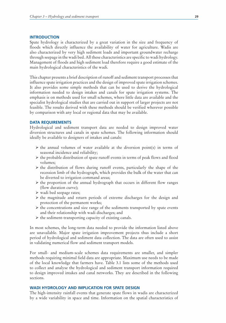
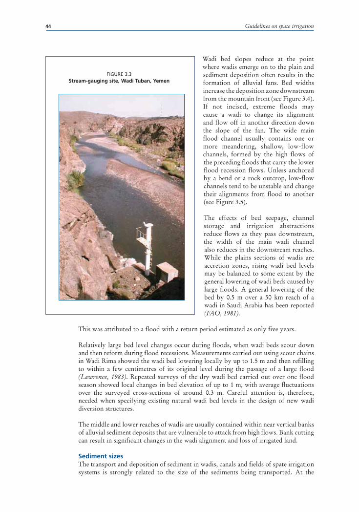
In the upper reaches, wadi channels are often contained within narrow valleys, and sometimes flow through gorge sections that act as natural hydraulic controls. In the larger wadis in Yemen and Eritrea, gorges located close to the mountain front are selected for stream-gauging sites (see Figure 3.3).
1 Calculations can be conveniently carried out using the ‘irregular cross section’ option in the DORC design tools section of HR Wallingford’s ‘SHARC’ sediment management software. The software and manuals can be downloaded at http://www.dfid-kar-water.net/w5outputs/software.html.
Guidelines on spate irrigation44
Wadi bed slopes reduce at the point where wadis emerge on to the plain and sediment deposition often results in the formation of alluvial fans. Bed widths increase the deposition zone downstream from the mountain front (see Figure 3.4). If not incised, extreme floods may cause a wadi to change its alignment and flow off in another direction down the slope of the fan. The wide main flood channel usually contains one or more meandering, shallow, low-flow channels, formed by the high flows of the preceding floods that carry the lower flood recession flows. Unless anchored by a bend or a rock outcrop, low-flow channels tend to be unstable and change their alignments from flood to another (see Figure 3.5).
The effects of bed seepage, channel storage and irrigation abstractions reduce flows as they pass downstream, the width of the main wadi channel also reduces in the downstream reaches. While the plains sections of wadis are accretion zones, rising wadi bed levels may be balanced to some extent by the general lowering of wadi beds caused by large floods. A general lowering of the bed by 0.5 m over a 50 km reach of a wadi in Saudi Arabia has been reported (FAO, 1981).
This was attributed to a flood with a return period estimated as only five years.
Relatively large bed level changes occur during floods, when wadi beds scour down and then reform during flood recessions. Measurements carried out using scour chains in Wadi Rima showed the wadi bed lowering locally by up to 1.5 m and then refilling to within a few centimetres of its original level during the passage of a large flood (Lawrence, 1983). Repeated surveys of the dry wadi bed carried out over one flood season showed local changes in bed elevation of up to 1 m, with average fluctuations over the surveyed cross-sections of around 0.3 m. Careful attention is, therefore, needed when specifying existing natural wadi bed levels in the design of new wadi diversion structures.
The middle and lower reaches of wadis are usually contained within near vertical banks of alluvial sediment deposits that are vulnerable to attack from high flows. Bank cutting can result in significant changes in the wadi alignment and loss of irrigated land.
Sediment sizes The transport and deposition of sediment in wadis, canals and fields of spate irrigation systems is strongly related to the size of the sediments being transported. At the
FIGURE 3.3Stream-gauging site, Wadi Tuban, Yemen

Chapter 3 – Hydrology and sediment transport 45
FIGURE 3.5Unstable low-flow channels, Wadi Zabid, Yemen
FIGURE 3.4Wadi bed widening after emergence onto the coastal plain, Wadi Laba, Eritrea

Guidelines on spate irrigation46
mountain fronts, wadi beds usually contain a very wide range of sediments ranging from surface layers of fine sand, silts and clays deposited during the recession phase of floods, through coarse sand and gravels forming the beds of low-flow channels, to shoals of cobbles and boulders. The underlying alluvium typically contains all these materials, along with very large boulders that may only be exposed and transported by the largest floods.
The active beds and deposition layers from past floods can usually be observed in exposed banks or at the lowest points excavated in the wadi beds. The wide range of sediment sizes observed in the bed at a typical upstream wadi diversion site is illustrated in Figure 3.6. The sizes of wadi bed material reduce and become more uniform in the downstream direction. Wadis usually have sand beds in their lower reaches.
Sediment transportIn most spate irrigation systems, only the largest floods are allowed to flow beyond the irrigated area. Smaller floods are either diverted to the fields, or seep into the wadi bed. Thus, although very large quantities of sediment are transported up to the first diversion point, usually very little sediment is transported beyond the irrigated area. Coarser sediments settle in the wadi channels and canals and finer sediments are deposited on the fields where farmers welcome sedimentation as a source of fertility. Figure 3.7 shows fine sediment deposit photographed twelve days after spate irrigation on a field in the Wadi Tuban system in Yemen.
Although management of sedimentation is a key factor in spate schemes, there is very little data to assist designers in assessing sediment transport and sedimentation rates or to design sediment management structures. The most reliable information has been derived from a small number of measurement programmes where pumped sampling
FIGURE 3.6Wadi bed sediment sizes - Structure 1, Wadi Zabid, Yemen
Size (mm)
Surface silt depositsBed material - small flow channel
Wadi bed pit smaples
% F
iner
0.001
20
40
60
80
100
0.01 0.1 1 10 100
100

Chapter 3 – Hydrology and sediment transport 47
equipment has been used to collect sediment samples from fixed nozzles at various depths from flood flows (Lawrence, 1986 and Mace, 1997). The limited information that is available suggests that:
� Total load sediment concentrations rising to and exceeding 100 000 ppm, or 10 percent by weight can occur in floods in some wadis. Sediment concentrations up to 5 percent by weight in floods are common.
� Sediment transport is dominated by the finer sediment fractions. The proportion of silt and clay in the sediment load varies widely during and between floods and between catchments but typically ranges between 50 and 90 percent of the total annual sediment load. As they are ‘supply controlled’, fine sediment concentrations do not correlate well with wadi discharge (see Box 3.3 for fine sediment concentration in Balochistan and Eritrea).
� The sand load transported in suspension in wadi flows, which will be diverted to canals even at well designed intakes, is also relatively fine (generally between 0.1 and 1 mm) when compared with the parent bed material. Estimates of the sand load can be derived from empirical equations but should be supported, wherever possible, by measurements of the sand load variations during floods.
� Coarse sediments transported near the wadi bed by rolling and sliding represent only 5 percent or so of the total annual sediment load. Sediments of this size range from coarse sand, through gravel, to cobbles and in some cases boulders. They settle and block intakes and canals. Estimates of bed load sizes and concentrations are needed to design sediment control structures where these are included in larger major intakes. These are usually derived from empirical equations. However, their measurement is only feasible with the use of specialist equipment.
Measuring sediment size distributionThe need to control coarser sediments that settle in canals is discussed in Chapter 4. Sediment transport computations carried out to design sediment control structures are based on wadi bed sediment size distributions. They are too complex to be included in these guidelines, but the method of assessing sediment size distribution is described briefly below (Lawrence, 2009).
FIGURE 3.7Sediment deposits, Wadi Tuban, Yemen

Guidelines on spate irrigation48
Sampling of bed material in coarse-grained channels requires a very large sample size to represent the sediment distribution accurately. When the surface layers consist mostly of gravel cobbles and boulders, a randomized point-counting method of the bed material can be used as an alternative to sieving. This can be achieved by using a random walk to select stones for measurement:
� Starting at the centre of a shoal of coarse sediment, take one pace in a random direction and select the pebble/gravel/cobble lying directly at the end of your shoe.
� Pick up and measure the intermediate axis of this stone in millimetres. � Repeat, changing direction after each pace so that sampling is random and taking care not to look at the wadi bed when pacing. Avoid the temptation to ‘select’ large gravels and cobbles. Ignore sediments smaller than 1 mm.
From these measurements a grading curve for the bed material can be produced by ranking the sizes of the intermediate axis in ascending order and plotting against a cumulative percent by number. The number of measurements needed depends on the range of sizes being sampled, but generally one hundred measurements will provide sufficient accuracy. Ideally this procedure should be repeated several times at different shoals and the representative D84 size taken as the mean of the individual D84 sizes.
BOX 3.3
Wash load (fine sediment) concentrations for the Chakker River in Balochistan, and Wadi Laba (Pakistan)
The similarity of the gradients of the relationships between sediment concentration and discharge for the two wadis is fortuitous. Typically, the exponents in power law relationships for fine sediments transported as wash load can vary between Q0.3 and Q1.2.
0.1 1 10
Discharge m3/s
Co
nce
ntr
atio
n p
pm
100 1000
1 000
100
10 000
100 000
1 000 000

Chapter 3 – Hydrology and sediment transport 49
For large canals with very coarse bed material, either of the methods listed above can be used to estimate discharges from water levels. For channels or canals with sand beds, an alluvial friction predictor is recommended to estimate channel roughness from bed material size and hydraulic conditions. One of the methods available in the design tools ‘DORC’ option of HR Wallingford’s SHARC sediment management design software is recommended2.
Estimating sedimentation rates on spate irrigated fieldsSoils in spate areas are largely built up from wadi sediments. In some locations soil depths of 500 mm thickness have been developed over a period of 3–4 years, and alluvial sediment deposits many metres thick are observed in some of the older spate-irrigated areas. The rate that soil build up varies from location to location, depending on the sediment yield from catchments, and on the position within a scheme. Sedimentation rates are higher in the upstream fields, as they are irrigated more frequently and are also closer to the wadi, and there are fewer opportunities for fine sediments to settle out of the short, steep canals linking wadis to the fields.
The size range of the sediment deposits at different locations depends on the relative rates of sediment transport and deposition through the canal system. Some fine sands that are transported through the canals may settle in the upstream fields, while finer sediments, silts and clays tend to be transported further. Table 5.1, in Chapter 5, provides information on the annual rise rate for fields in spate-irrigated areas.
In existing schemes, past increases in field levels can therefore be assessed from the thickness of alluvial sediment deposits and the number of years that the scheme has been diverting water. This provides a guide to the expected future rates of rise of field levels that will need to be taken into account when the command levels for improved intakes and other hydraulic structures are being determined. For new schemes, particularly in regions that do not have nearby existing spate-irrigated areas, estimating future command changes is more difficult. However, approximate estimates can be made if information is available on catchment sediment yields, or the sediment concentrations in floods.
Catchment sediment yields, expressed in t/km2.y, can be converted to a sediment concentration by weight in ppm by dividing the product of the catchment area and the sediment yield by the annual runoff volume in million m3. Sediment concentrations in floods can be measured by taking frequent, regular, surface bottle samples in floods and, in the simplest form of analysis, by averaging the sediment concentrations in the bottles. Care should be taken to ensure that average samples are collected during flood flows.
The annual rise in the command levels of upstream fields can then be estimated from:
Δl = n . d . conc. / (1.4 106)where:
Δl = Annual rise in the level of the upstream fields (m) n = Number of irrigations during a year d = Depth of water applied per irrigation (m) conc. = Sediment concentration by weight (ppm).
2 The software and manuals can be downloaded at http://www.dfid-kar-water.net/w5outputs/software.html

Chapter 4 – Water diversion and control sutructures 51
Chapter 4
Water diversion and control structures
SUMMARYExperience shows that the most successful spate irrigation improvement projects do not significantly alter the way spate irrigation is practised. They combine the advantages of traditional systems with those of more permanent and less labour-intensive structures.
Improvements to spate systems must be designed so as to reduce the labour required to maintain intakes, improve the control of water within the distribution systems and minimize the capacity of large floods to damage canals and fields. They must guide and split flood flows, rather than constrain them, avoid excessive sediment load in spate systems and ensure that suspended sediments are deposited on the land and not in the canals. Their design must also ensure that they can cope with frequent and sometimes large changes in wadi bed conditions. At the same time, proposed improvements must recognize and respect the established system of water allocation arrangements, priorities and amounts, and avoid unintentional alteration of water distribution within the watershed between upstream and downstream water users.
The range of technically and economically viable design options must take into account the experience that the farmers have of the systems and of wadi flow. The role of engineers is primarily to assist farmers in selecting the most appropriate options that improve upon traditional schemes without introducing unnecessary changes. Farmers should therefore be consulted and involved in the planning, design, execution and operation of the rehabilitation and improvement works. Consultation is thus fully interactive and continuous, ensuring that the local situation is fully understood and reflected in the improvements. It is of paramount importance to understand farmers’ irrigation practices, priorities and risk management strategies.
Engineering interventions involved in spate scheme improvement can be clustered into three groups: diversion structures (intakes), canals and water control/dividing structures and wadi training structures, including bank protection and embankments. In general, designs should be robust enough to take into account the uncertainty in prediction of flood sizes and patterns. Cost/benefit considerations will to a large extent dictate the alternatives selected, such as the use of fuse plugs to reduce the cost of permanent diversion weirs but still to maintain the design return period. Interventions need to be seen in a holistic manner and the engineers should give adequate and balanced consideration to both upstream and downstream water users and consider both overall water balance and allocation. Sedimentation problems linked to permanent structures must be manageable with the use of realistic levels of local resources, funds and skills so that sustainable levels of maintenance can be assured.

Guidelines on spate irrigation52
The following guiding remarks can be given for engineering interventions in the different types of spate systems described in Chapter 1:
� For traditional small schemes managed by farmers, options usually include the provision of more durable simple diversion structures, constructed from gabions, rubble masonry or concrete, with structures properly designed to resist erosion, scour and overturning and simple enough for farmers to maintain with indigenous skills and locally available materials.
� For new small schemes where spate irrigation is being introduced, the engineering options for traditional schemes may be applied, but the provision of a simple permanent structure and bed bars will often be a better option (compared to traditional structures) when farmers do not have experience of using traditional diversions.
� For medium-scale to large-scale traditional schemes, which are under farmer management and are treated as a number of small independent systems: this approach has the advantage that farmer user groups and arrangements for water distribution and maintenance remain unchanged. In some cases it may be prudent to work on the tail-end systems only. Many past modernization practices have tended to replace numerous small intakes by a limited number of major diversion structures, connecting the existing spate systems through a single main canal. While this may have advantages in terms of costs, the major disadvantage of the single new intake approach is that it reinforces the upstream users’ control over diverted flows and reduces access to water for downstream users, who can no longer divert water directly from the wadi. This often leads to a substantial modification of established water distribution practices without farmer agreement. In cases where such an option is retained, discussions with all water user groups are needed to ensure that changes in traditional water allocation arrangements and water management practices are understood, equitable and accepted by all.
� In large wadis subjected to very high spate discharges, more experienced engineering expertise is needed to ensure that diversions are sufficiently robust to provide durability and less risk of failure or severe damage. However, these approaches, using more conventionally engineered structures, need to be balanced against costs (capital and recurrent) and the flexibility needed to meet the farmers’ requirements and expectations and to adjust to the changing circumstances that are inherent in spate systems.
� For large schemes that have been improved in the past and provided with technically more complex infrastructure, such as more permanent diversion and water control structures, technical, social and environmental reviews will be needed. Experience has shown that operation and maintenance costs and negative impacts on existing water distribution practices and rights are systematically underestimated and that this leads to poor management, degradation of irrigation infrastructure and inequity in access to water. A careful assessment of all costs and benefits related to such schemes is therefore necessary to ensure that they are financially, socially and environmentally sustainable, that the improvements guarantee that adequate water is diverted to all farms (in comparison with traditional allocations) and that water allocation arrangements and water management practices are understood, equitable and accepted by all.
Diversion structures – traditional intakes can take one of two forms: spur-type deflection, and bund-type diversion. While they are simple structures, they have enabled spate irrigation to be sustained for many years with only local materials

Chapter 4 – Water diversion and control sutructures 53
and indigenous skills. They are characterized by flexibility to changing wadi bed conditions, suitability for construction and maintenance by local farmers with local materials, a relatively high level of efficiency in water use and the ability to avoid excessive sediment transport in the canals. These advantages are obtained at the cost of regular destruction and reconstruction of intake structures after each large flood and environmental damage. The major disadvantage associated with traditional diversion structures lies therefore in the amount of labour needed to maintain and reconstruct intakes that are damaged or washed out by large floods and the continual use of new brushwood and tree material needed to reinforce the bunds.
There are several options for improving diversion structures, which depend on the site conditions, the available resources and farmers’ preferences. These options essentially include:
� more durable diversion spurs with breach or overflow sections; � improved diversion bunds (including the use of fuse plugs and bed bars); � controlling the flows admitted to canals (natural orifice control or more formal gated intake structures);
� rejection spillways; � a combination of the above.
Typically, improved diversion structures may include the following components:
� a bed stabilizer (bed bar) or a raised permanent weir, to control and fix the bed and hence the water levels at the division point. In most cases weirs are only needed to provide command to the immediately adjacent land, as both the land and wadi bed slopes are steep and most of the land is naturally commanded;
� a fuse plug, in earth or wadi bed material, to be used in conjunction with a permanent weir structure spanning only part of the wadi width, to increase the return period of the design and thereby reduce costs but still protect the intake and weir from exceptional floods;
� a scour or under-sluice, to exclude very coarse sediment material from the canal during periods of high flows. When gated, sluices can usually only be operated for the short periods when the wadi flows exceed the canal discharge and in agreement with water users,
� a breach bund made of local material, located just downstream from the intake structure and built over a bed bar that controls the location of the diversion bund and offtake. It will be breached during high flood flows and thereby return to the downstream river bed large amounts of coarse sediments transported by such floods and avoid heavy sedimentation of canals and blocking of intakes,
� a canal head regulator or intake, controlled by gates or orifice flow, to regulate the flows entering the canal and share water among several intakes. In large systems characterized by fixed intakes, gates are needed for sharing the water between the intakes. In these situations, a local experienced community operator assesses the arriving floods (timing, duration, size) and adjusts the openings in accordance with agreed schedules and water allocations; and
� guide or divide walls.
Canal design – the dimensioning of spate canals does not follow classical irrigation design. In spate irrigation systems the objective is to divert the maximum possible amount of water during the very limited duration period of the spate flood to

Guidelines on spate irrigation54
reach as many of the fields as possible. Intakes and canals thus have a much larger discharge capacity per unit area served than would be the case in perennial irrigation schemes (10–100 times greater). Discharge capacities for intakes and canals are determined from an assessment of the distribution and size of flood flows within the annual hydrograph; the duration and variation of discharge during each flood event; and, as water is applied before crop planting, soil water-holding capacity in relation to assumed crop water needs, rather than to actual crop water requirements during the growing season. Actual canal discharge varies rapidly over the full range of flows from zero to the maximum discharge. Sediment loads in spate systems are very high and canal designers are not free to set the canal cross-section and slope to carry the required dominant discharge. Instead, they must make sure that flow velocities are maintained at relatively high levels to ensure an appropriately high sediment-transporting capacity.
This contrasts with conventional canal designs for irrigation systems, that are based on meeting actual crop water needs with supplied water relatively free of sediment and flow velocities determined by using a Froude number less than 0.7–0.8 (i.e. sub-critical flow + safety factor), for which a fairly narrow range of design discharges (0.7–2.0 l/s/ha), canal capacity and sections adopted are hydraulically efficient and cost-effective.
Traditional canals in spate schemes usually adopt prevailing land slopes without drop structures. Although these slopes are often much steeper than those adopted for canals used in perennial irrigation systems, head-cutting erosion is normally minimal as bed material is far coarser than in conventional earth canals. In addition, although local scours may occur, any corrosion will be filled by sediments as the spate flow recedes and the velocity in the canals drops. Typical canal structures in spate irrigation systems are flow-dividing structures, field offtakes and in-field check and drop structures. In improved spate systems, checks and drops are often included. Many of these water control structures introduced as part of scheme improvement interventions are similar to those used in conventional irrigation. However, the following points must be taken into consideration when improving (or extending) spate canal systems:
� Improving existing canal networks can give better water control and overcome some disadvantages of the field-to-field water distribution system but may require a change in the way that water is distributed. Any modifications could impact existing water rights and rules and thus need to be discussed and negotiated in advance with the farmers.
� Spate irrigation relies upon water application carried out as quickly as possible. The improved canal network must ensure that this continues and maximizes the areas irrigated in the short spate flow periods. This is particularly important to downstream farmers, whose time of exposure to irrigation flows is far less than that of upstream farmers, who access water from most floods in most years.
� Farmers’ prior agreement to proposed changes and their full understanding of the implications for water allocation and distribution is essential for sustainable changes. In particular, the use of gated structures, either at the intake or in canals, must be determined with a clear understanding of operational implications for downstream users.
� As spate flows occur at short notice and are of short duration, choice of gate design and operating system must reflect the need for rapid opening and closing of the gates and be related to the peak time of the flood hydrograph. Manual systems are usually too slow even with a high gain mechanism; electrical

Chapter 4 – Water diversion and control sutructures 55
gates rely on the availability of power, which is often lacking at key moments; hydraulic gates are more expensive but are the most suitable, as they can be operated quickly and in response to rapid changes in the flood hydrograph.
� Where canals are performing reasonably satisfactorily, the design of improved or extended canals should be based on the prevailing slopes and cross-sections and supported by survey data. Canal design methods that simulate existing canal slopes and dimensions should be utilized both to check existing designs and extend designs to new canals.
� Velocities in the canal network should be maintained as close as is possible at a constant level throughout to ensure high sediment-transporting capacity and to minimize deposition in the canals (similar to the situation observed in traditional canals).
� In flatter areas with alluvial soils, scour damage should be avoided through adoption of regime theory, selection of appropriate canal dimensions and slope, division of flows and the provision of controlled intakes and embankments and associated bank protection works.
Sedimentation – wadi beds and banks are continually affected and eroded by large floods. This has implications for associated spate irrigation schemes. Wadi beds can be significantly lowered (both locally and permanently) during the passage of large floods and leave the invert of traditional intakes well above the new scoured wadi bed level, so that it is impossible to divert water into the canal system. Providing engineered structures (bed bars or low overflow weirs) to control wadi bed levels is a viable option, but can be difficult to justify in small spate schemes or where the wadi course is wide. In such cases, it has been found that providing farmers with access to bulldozers so that they can quickly reconstruct bunds across the wadi after major floods can be economically more attractive.
The ability to cope with changes in wadi beds and high sedimentation rates in the command areas and canals is critical to the success of spate irrigation. New intakes and canals have to be designed to cope with changes in wadi bed and/or field levels rising up to 50 mm/year. When new diversions are proposed, the following measures are recommended:
� Estimates of the rise in command levels expected over the design life of structures (>25 years) should be developed and used to design weirs, intakes and water control structures to maintain the irrigable command area. One option is to provide moveable stop logs that are progressively raised in line with the rising bed (an approach adopted in the Gash in Sudan). Alternatives at field level include increasing the gross irrigable area but maintaining the net irrigable area as some land goes out of command.
� Intakes associated with permanent raised weir structures should be provided with effective sediment sluices that are designed to be operated during the very short periods when flood flows exceed the diverted flows. Small settling basins designed to trap coarse sand, gravel, and larger sediments, before they can enter, settle and block canals, are also an option in these situations, provided that they are designed for easy, affordable and cost-effective removal of sediment by farmers’ organizations immediately after floods.
� Where intakes are not associated with permanent raised weirs, the provision of bed bars and breachable bunds, built from local materials, on top of the bed bars provides an improved intake that works in a similar manner to sediment management in traditional systems.

Guidelines on spate irrigation56
River training – The scouring of wadi banks, undercutting at the outer curves of meanders and sedimentation at the inner curves during large floods erodes away valuable irrigated land and threatens villages and canals running parallel to the wadi banks. It is usually impossible to justify protection against such damage from large floods with conventional river-training works, because of the high costs involved when compared with the low value of the land and the crops that are grown. Often the best option is a combination of vegetative protection and mechanical control measures. All river training and bank improvements must form part of a complete plan to ensure that problems are not treated in isolation with the result that they are just moved to another location.

Chapter 4 – Water diversion and control sutructures 57
INTRODUCTION – LEARNING FROM PAST EXPERIENCEThe irrigation infrastructure, patterns of water distribution and arrangements for operating and maintaining traditional spate irrigation systems have evolved over time and adapted to the local conditions. Traditional spate irrigation systems divert water from spate wadis through the use of simple, locally developed and improved structures. Over many years, farmers have developed local knowledge of locating and constructing diversion structures, managing flood waters and organizing water distribution.
Traditional diversion and distribution structures enable water to be diverted from uncontrolled ephemeral rivers through the use of only local materials and indigenous skills. When multiple traditional diversion structures are used along a wadi, relatively high overall water diversion efficiency can be achieved. The principal disadvantage of traditional diversion methods is the excessive inputs of labour needed to rebuild the structures, which are frequently damaged or scoured out by flood flows, sometimes by design, and which annually require significant amounts of local timber and brushwood material for reconstruction.
Over the last three to four decades, relatively sophisticated and costly diversion structures, linked to new canal systems, have been introduced in some countries to modernize and improve the performance of traditional systems, e.g. Yemen, Pakistan, Morocco, and Tunisia. These well-intentioned interventions were designed to eliminate the need for the frequent reconstruction of traditional intakes which are regularly damaged by the larger spate floods, and in some cases to increase the volumes of water available for irrigation. While new engineered diversion and water control structures have mostly solved the durability problem, they have often failed to provide some of the other benefits that were anticipated, especially improved water availability for all. This disappointing performance has been variously attributed to:
� an increased inequity of water distribution, resulting from the construction of permanent diversion structures at the head of spate systems, which gave the upstream farmers control over a large proportion of the available flows, to the detriment of downstream irrigators (see example in Box 4.1);
� inadequate intake capacity, and hence water, in the spate networks through a failure to appreciate the link between exposure time to, and duration of, spate floods;
� problems due to high rates of sediment deposition in the fields and canals, resulting in the need for frequent desilting (see example in Box 4.2);
� the introduction of an operating authority who has the technical skills needed to operate and maintain modernized infrastructure but who has also reduced the farmers’ role in diverting and distributing water and often ignores traditional practices;
� the unrealistic assumptions concerning levels and costs of operation and maintenance of spate systems (mostly canal and sediment basin desilting), required to keep conventionally designed irrigation canal networks running under spate conditions;
� failure to relate system design and operation to farmer management and likely levels of funding that they could raise for annual operation and maintenance; and
� failure to achieve an expected increase in irrigated area owing to over-optimistic assumptions about water resource availability (amounts, duration of floods and shape of the hydrograph) and the water diversion efficiency that can be achieved with rapidly varying spate flows and manually operated control gates.
These problems in many cases result from comparing the diversion efficiency, and hence intake capacity, of well designed permanent gated diversion structures with the much lower efficiency obtained from a traditional free intake and incorrect assumptions

Guidelines on spate irrigation58
BOX 4.1
How structural improvements modify the balance of power: the example of Wadi Mawr, Yemen
A new irrigation infrastructure in Wadi Mawr was commissioned in the mid 1980s. Located on the Tihama plain in Yemen, this was one of the last Tihama wadis to be modernized. The diversion structure was developed on the basis of lessons learned from earlier spate improvement projects. It includes what is probably the most sophisticated spate irrigation intake constructed anywhere in the world. A large proportion of the annual runoff in Tihama wadis consists of base and lower recession flows and high diversion efficiency can, in theory, be achieved with a single intake located at the head of the scheme which diverts only relatively low flows. The intake was thus designed to divert flows of up to 40 m3/sec and was located on the north bank of the wadi at the head of the existing irrigated area. It was estimated that 88 percent of the mean annual wadi discharge would be diverted to new canals running down both banks of the wadi to supply water to the 39 existing primary canals (a siphon transfers water under the wadi to a supply canal located on the south bank).
The intake structure (see figure below) consists of a raised weir, a deep scour sluice with three gates and four head regulator gates feeding twin sediment-settling basins. The settling basins were designed to be flushed when sufficient water was available in floods, to flush coarse sediments trapped by basins back into the wadi. As up to 14 gates need to be operated during spates, electrically powered gates were provided.
This structure provides an example of a well engineered large-scale spate diversion system. Yet the operation of the intake, sluice and canals has been severely compromised by powerful landlords in the upstream part of the irrigation scheme, who have prevented the sluice and sediment-flushing facilities from working as planned so as not to ‘waste’ water. Flows have been diverted at the intake and commandeered for use mostly in the upstream part of the system, a new unauthorized canal has been constructed and water has been sold to farmers in another command area, outside the boundaries of the Wadi Mawr system. Farmers on the south bank and lower parts of the system have lost access to the water that they could have formerly diverted and have had to rely on the reduced water volumes available in the infrequent, very large floods that pass over the diversion weir. This case shows how an improved diversion system that should have benefited all farmers in a scheme was diverted from its intended role for the benefit of a few.

Chapter 4 – Water diversion and control sutructures 59
relating traditional seasonal irrigation with spate irrigation. Predicted diversion efficiency at a new formal intake needed to be compared with the combined diversion efficiency of the many independent traditional intakes that it replaced, including intakes outside the formal scheme area which utilized excess flood flows that do not occur every year. In other cases, over-optimistic assumptions of increases in cropped areas following modernization may have been influenced by the need to justify large investment projects with conventional cost/benefit criteria without an understanding of the farmers’ concept of areas irrigated in below normal, normal and high runoff years.
Experience has shown that successful design of improved spate irrigation structures needs a sound understanding of the water-sharing and institutional arrangements that have underpinned the success of traditional systems for centuries, as well as the more obvious engineering, hydrological, agronomic and economic issues. For engineering interventions to be successful, they must:
� replicate as far as possible the way in which water has been traditionally diverted/abstracted and in many instances build on these traditional systems;
BOX 4.2
Example of design problems in modernized systems
In Yemen, several large spate irrigation systems located on the Tihama coastal plain were modernized in the 1980s. They include Wadi Zabid, Wadi Rima and Wadi Mawr. The design of the modernized intakes became more sophisticated over time. The first scheme to be modernized, Wadi Zabid, consisted of five new permanent diversion weirs, most with canal intakes on both banks. The intakes immediately experienced diversion and sedimentation problems and, before its recent rehabilitation, the scheme was operated like a traditional system, with diversion essentially controlled by bunds built into the wadi bed by bulldozers, to guide flows towards the gated canal intakes (see figure below). Frequent canal de-silting was needed to maintain canal flow capacities.

Guidelines on spate irrigation60
� recognize the unit flows for traditional spate systems that range from 10 l/s/ha (the Tihama average norm) to over 100 l/s/ha in some smaller wadis with short-duration spate flood flows;
� reflect the time commitments and technical knowledge of the farmers, thereby reducing labour commitments for routine and emergency maintenance and facilitating farmer operation;
� facilitate the control of large flood flows, to reduce damage to canals and field systems;
� as far as possible, replicate water distribution in line with accepted rules and rights, while providing flexibility to accommodate future changes in water distribution and cropping;
� ensure a right balance between the needs of different water uses and users (agriculture, drinking water, downstream users, etc);
� improve the capacity of the systems to function with high rates of sediment transport; and
� improve the ability to cope with the frequent big changes, resulting from large floods, in the levels and alignments of unstable river channels.
While many of these features were being promoted in spate improvement projects more than twenty years ago, providing them in medium-scale and large-scale spate schemes at an acceptable cost (both capital and recurrent) continues to challenge designers, irrigation engineers, aid agencies and donors. Improvements requested by farmers are usually aimed at reducing the excessive maintenance burden, through provision of more robust and more permanent diversion and water control structures. As spate systems are often diverting a substantial proportion of the annual flow volumes during relatively short periods to produce low-value subsistence crops, the economic returns from investments in new diversion and water control structures may be quite small. The challenge is thus to provide affordable improvements to the existing infrastructure that match as closely as possible the desired engineering interventions discussed above.
Often expected economic returns from improvements in spate irrigation are relatively marginal and can only warrant low-cost improvements. These low-cost improvements in spate infrastructure in most cases imply higher annual maintenance costs than more expensive structures, but they may also provide the added advantage of flexibility that is needed in the dynamics of spate irrigation to adjust to a rapidly changing physical environment. In some cases, where other factors come into play such as poverty reduction, groundwater recharge and improved reliability of water supplies in severely drought-affected areas, higher-cost engineering improvements may be justifiable, provided that the interventions proposed do actually meet these criteria and truly benefit the target groups. Where spate irrigation is being introduced into new areas, farmers will probably not have the traditional indigenous skills needed to divert and distribute spate flows through the use of traditional structures. In these cases again, simple but improved diversion structures, with permanent gated intakes and canal water control structures that are easily operated, may be needed.
The overriding principle is that there is no single approach to the design of improved spate systems. Specific requirements vary widely between, and in some cases within, schemes, but before proposals are finalized, it is essential that engineers fully understand the way in which the farmers’ system has operated and farmers truly understand and comprehend what the engineers are proposing for them. It is important to keep a large repertoire: in some areas, permanent headworks will be useful, in other areas the use of gabion flow dividers/splitters or the engagement of bulldozers to construct earthen structures will be appropriate.

Chapter 4 – Water diversion and control sutructures 61
The engineering structures involved when spate schemes are improved can be described under three headings:
� diversion structures (intakes); � spate canals and water control/dividing structures; and � bank protection and wadi-training structures.
For each category, traditional structures are first described, followed by a discussion of improvement options.
DIVERSION STRUCTURES (INTAKES)Intakes in spate systems have to divert large and varying levels of flood flows, delivering water to canals at a sufficiently high level to ensure command over the irrigated fields. They need to prevent large uncontrolled flows from entering canals, so as to minimize damage to channels and field systems and limit the entry of the very high concentrations of coarse sediments that are carried especially in the larger floods. These functions have to be achieved in unstable wadis, characterized by occasional lateral movements of low-flow channels within the wider wadi cross-sections, bank cutting and vertical movements of the wadi bed caused by scour and sediment deposition during floods. Intakes must also function over the longer term with rising irrigation command levels caused by sediment deposition on the irrigated fields and aggradation and degradation of wadi bed levels due to changing hydrological conditions, climate change and catchment deforestation.
Canals need to convey large volumes of water to fields quickly in the short periods when flood flows occur. The timing, duration and maximum discharge of spate flows are unpredictable and thus canal capacities have to cope with a wide range of design conditions. Water distribution systems developed for perennial irrigation are thus not appropriate for spate systems as canal capacities are determined for a relatively narrow and predictable range of design conditions. Traditional intakes and their modern replacements can be adapted to meet spate design conditions, although the design parameters will be very different, resulting in large differences in cost and maintenance requirements.
Traditional structures Traditional intakes can take one of two forms. These are the spur-type deflector and the bund-type diversion.
Spur-type deflectorDeflecting spurs are mainly found in upstream wadi reaches, soon after the wadi leaves the foothills and begins to enter the flood plains. In these locations, longitudinal slopes are steep, bed materials coarse and water velocities during flood flows very fast. The structures consist of a spur, usually built from wadi bed material and reinforced with brushwood and other more durable materials brought down during floods. They are located within the main wadi bed and aim to divide or split the flood flows, with the larger part of the flow being encouraged to continue downstream. From the main deflector, a smaller bund is constructed across and extending up the wadi bed at a relatively sharp angle both to intercept low flow and divert it via the low-flow channel to an un-gated canal intake (see Figure 4.1). Three examples of traditional spur-type intakes from Ethiopia, Yemen and Pakistan are shown in Figures 4.2, 4.3 and 4.4.

Guidelines on spate irrigation62
Figure 4.2 shows a spur intake in an upstream view from the head of a canal diverting water from a small sandy-bed spate river located in the south of Ethiopia. The spur, well located at the outside of a bend where it intercepts the low-flow channel, is constructed from tree trunks driven into the wadi bed, sealed woven branches, brushwood and sand from the river bed.
Figure 4.3 is taken from Wadi Rima in the Tihama Plain bordering the Red Sea in western Yemen. It shows the upstream end of a typical traditional spate intake constructed from cobbles and gravel, reinforced with brushwood, located at the outside (left bank) of the wadi bend. A new permanent diversion weir was constructed a few kilometres upstream from this intake in the 1980s but, as the intake capacity was insufficient to meet all of their water needs, farmers continued to use this and other traditional intakes to utilize excess flood flows from the larger floods that pass over the new diversion weir. This weir was one of the first in the programme of donor support to improving spate irrigation systems in the area and subsequent designers could have learned many lessons from these experiences.
FIGURE 4.1Deflecting spur-type traditional intake
Wadi
Wadi
to fields
Deflecting Spur
FIGURE 4.2Traditional spate irrigation intake in Ethiopia

Chapter 4 – Water diversion and control sutructures 63
Figure 4.4 shows a spur-type intake constructed from wadi bed material and pushed up by bulldozer at the outside of a river bend in a spate river in Pakistan. The wide, shallow cross-section of the diversion channel, typical of canals in spate systems, and the fine sediment deposits that have settled in the intake channel are well recognized. The photo also illustrates the intention of the farmers to take only a proportion of the peak wadi flood flow, at the same time abstracting as much of the lower and medium flows as possible. Although the examples shown above encompass intakes constructed in different ways, in wadis of differing sizes, catchment areas and flow characteristics and at widely separated geographical locations, they share many common features they:
� are located at the outside of relatively mild wadi bends, where the deep water channel is scoured in floods, and where lower flows are channeled during flood recessions;
� consist of low spurs extending at a slight angle out into the wadi to intercept the low-flow channel and divert water to canals;
FIGURE 4.3Traditional spate irrigation intake in Yemen
FIGURE 4.4Traditional spate irrigation intake in Pakistan
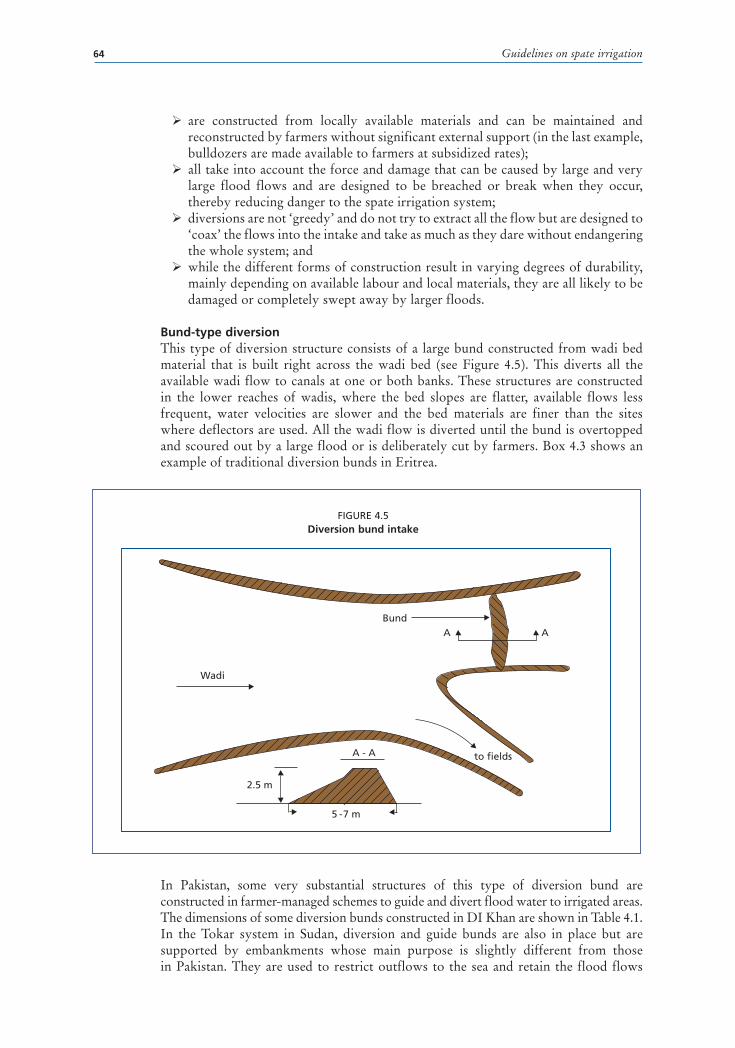
Guidelines on spate irrigation64
� are constructed from locally available materials and can be maintained and reconstructed by farmers without significant external support (in the last example, bulldozers are made available to farmers at subsidized rates);
� all take into account the force and damage that can be caused by large and very large flood flows and are designed to be breached or break when they occur, thereby reducing danger to the spate irrigation system;
� diversions are not ‘greedy’ and do not try to extract all the flow but are designed to ‘coax’ the flows into the intake and take as much as they dare without endangering the whole system; and
� while the different forms of construction result in varying degrees of durability, mainly depending on available labour and local materials, they are all likely to be damaged or completely swept away by larger floods.
Bund-type diversionThis type of diversion structure consists of a large bund constructed from wadi bed material that is built right across the wadi bed (see Figure 4.5). This diverts all the available wadi flow to canals at one or both banks. These structures are constructed in the lower reaches of wadis, where the bed slopes are flatter, available flows less frequent, water velocities are slower and the bed materials are finer than the sites where deflectors are used. All the wadi flow is diverted until the bund is overtopped and scoured out by a large flood or is deliberately cut by farmers. Box 4.3 shows an example of traditional diversion bunds in Eritrea.
In Pakistan, some very substantial structures of this type of diversion bund are constructed in farmer-managed schemes to guide and divert flood water to irrigated areas. The dimensions of some diversion bunds constructed in DI Khan are shown in Table 4.1.In the Tokar system in Sudan, diversion and guide bunds are also in place but are supported by embankments whose main purpose is slightly different from those in Pakistan. They are used to restrict outflows to the sea and retain the flood flows
FIGURE 4.5Diversion bund intake
Wadi
to fields
BundA A
A - A
2.5 m
5 - 7 m

Chapter 4 – Water diversion and control sutructures 65
within the middle delta, which is the most suitable land for irrigation. The Tomosay embankment is the biggest and most important. It extends for about 50 km along the western limit of the Tokar system and guides flow to the middle delta and away from the western delta. Only one main diversion bund exists, the Tomosay bund, and this is supported by smaller diversion bunds divided into three areas. No canal network exists, water being allowed to flow as a wide and shallow sheet over the area to be cultivated. This is a unique type of system that relies upon a high standard of land preparation and water management. In recent times, this has been lacking and thus the area irrigated is far less than the potential and historically irrigated areas.
BOX 4.3
Traditional bund intake under construction using draught animals in Eritrea
The figure below from the Red Sea plains in Eritrea shows a bund being constructed from wadi bed sediments dragged up by draught animals and scraperboards. Construction or reconstruction of bunds by using traditional methods obviously requires a very large input of labour and resources and a high degree of organization.
TABLE 4.1Dimensions of some diversion bunds in Di Khan in Pakistan
Location Length
(m)
Height
(m)
Width
(m)
Sad Swad 351 3.2 10.4
Sad Rabnawaz 754 7.0 12.0
Sad Dinga 330 1.9 15.1
Gandi Abdullah 178 8.0 14.0
Gandi Booki 1 350 3.0 8.0
Gandi Mullawali 87 1.9 4.5

Guidelines on spate irrigation66
Several very subtle factors need to be considered in the design and construction of soil bunds:
� The location and height of the bund are chosen in such a way that they do not cause unwanted flooding of other areas.
� In case of a diversion bund across the wadi with a single offtake, the preference is for the bund to be constructed as an arc or at an angle to the direction of flow of the wadi, to dissipate the energy of the flood.
� In case of a cross-bund with offtakes at both banks, the bund will be constructed in a straight line; depending on the height of the bund and the slope of the land, the cross-bund may serve several upstream offtakes. Practical experience has shown that this is more suitable than constructing the bund as a V-shape, as during large flood flows the bund needs to be breached in the centre to reduce damage. The V-shaped bund will direct the large floods towards the intakes and eventually to the command area where they can cause significant erosion and gullies and hence the complete loss of large segments of irrigable fields. Also the cross slope would mean that the apex of the V could not be in the centre of the river if flows are to be delivered to both sides in proportion to the areas commanded.
� The preference is to construct the soil bund with loamy soil. Gravel and saline soils should be avoided. The latter would lead to cracking of the soil bund and early breaching before overtopping occurred.
� Preferably the soil bund should be developed in layers, with each layer being 1–1.5 m thick. Compaction can be achieved by bulldozer, animal action or by hand.
� The soil bund is reinforced by intermixing it with vegetation, by laying brushwood along the lower toe or by stone pitching. In some cases short wooden poles are driven into the most exposed and vulnerable sections to fix the bund to the river bed and to reinforce the bund.
� Generally care is taken to avoid animals trespassing and trampling on the structure, as this would weaken the soil bunds.
In Pakistan, large bunds are constructed at the downstream end of degrading river reaches to encourage siltation and reverse a general lowering of river bed levels that causes large areas to go out of command. In these systems, sedimentation is being actively managed by farmers to restore the upstream river bed levels to an elevation that allows traditional upstream intakes to continue to function.
A special variation is the so-called retention dam that is built in some of Morocco’s wadis (Oudra, 2008). With these retention dams, all floodwater flow is dammed and, as a result, the dam inundates the valley bottom of the flood plain. The water infiltrates the soil, and the wetted area can be used for agriculture (mainly for cereals such as barley) or for pasture improvement. Retention dams are found in large river beds with a very low gradient that have soils suitable for cereal cultivation.
Advantages and disadvantages of traditional intakesTraditional diversion structures have been developed over many years and at some locations over centuries. While they may seem crude at first sight, they have been adjusted over time to the local wadi characteristics by the farmers and their ancestors and this has enabled irrigation to be sustained with the use of local materials only and indigenous skills. The advantages of traditional diversion structures can be summarized as having the following features:

Chapter 4 – Water diversion and control sutructures 67
� Flexible: the river bed topography, long section and the alignment of low-flow channels may change during medium or heavy floods, but the location and layout of traditional intakes can be easily adjusted to suit the changing wadi bed conditions. Diversion spurs can also be extended or moved upstream to retain command when sedimentation on the fields or in the canals starts to take fields out of command.
� Based on locally available technology: traditional intakes are constructed from local materials with the use of indigenous skills and can be maintained indefinitely by farmers without outside support. They are, however, associated with environmental problems resulting from unsustainable use of trees and brushwood and the difficulty over time in obtaining sufficient materials near to the diversion site.
� Relatively efficient: when a series of traditional intakes are used along wadis, high overall diversion water distribution efficiency can be achieved. Large floods may destroy diversion bunds supplying intakes at the head of large spate systems but, as the peak flood discharge passes down the wadi, the force of the flood peak is reduced, increasing the time of exposure to the flood flows so that significant flows can be diverted by the downstream intakes, once the upstream intakes have been destroyed. Although very high flood discharges occasionally occur, much of the annual runoff occurs in the medium to small wadi flood flows, that vary in duration and volume but can still be effectively diverted by traditional intakes without irreparable damage. These types of spate flows generally benefit the upstream spate systems that can use water from all spate events.
� Limit diversion of high flows and high sediment loads: the failure of deflecting spurs and diversion bunds and breach sections of the main intake canal at high wadi discharges abruptly lowers the water level at the canal intake. This reduces the discharges that are diverted, limits the damage to downstream canals and field systems and prevents the incursion of high concentrations of coarse bed material sediments, transported in the large floods, that would otherwise be deposited in the main canals and would not reach the fields.
However, there are some major disadvantages associated with traditional diversion structures. The most important is the enormous input of labour and resources needed to maintain and reconstruct intakes that are damaged, or washed out by the large floods (see Figure 4.6). In Eritrea, for instance, it is estimated that about 80 percent of the labour needed to operate and maintain a traditional spate irrigation system is devoted to maintaining and repairing intakes (Haile, 1999).
A second disadvantage associated with traditional diversion structures is that, although relatively high overall water diversion efficiency can be obtained with multiple intakes, it is not always possible to divert water where it is needed. When a large flood destroys upstream intakes, water from the following floods cannot be diverted until repairs have been completed. Conversely, if only small floods occur then these will either all be diverted at upstream intakes, or infiltrate into the wadi bed without reaching downstream diversion sites. In the Tihama plains in Yemen, losses within wadi beds have been estimated to represent about 2–3 percent of flood flows per km. In some cases, two floods can occur at an interval of a few days. Bund reconstruction thus requires the cooperation of large numbers of farmers and ready availability of replacement materials and equipment for the larger wadis. Even if these are at hand, vital floods can often be missed.
Over time, sediment deposition upstream from diversion bunds raises the upstream wadi bed and hence flood water levels – though the breaking of the bunds may locally reduce part of this effect. The sediment deposition may help in maintaining command

Guidelines on spate irrigation68
when sedimentation results in rising field levels, but can cause local changes in wadi slope, head-cutting and bank erosion. It may also increase the probability that a bund will overtop and scour out earlier than intended and lead to the construction of larger bunds by the farmers to divert the same quantities of irrigation water. A closely related problem is the silting of the flood offtake channels due to lack of maintenance or other reasons. This causes pressure to build up on the river cross-bunds as the water cannot ‘get away’ and may lead to their early collapse.
In addition, there is a danger that bunds will not be breached when planned and very large flows will be diverted into the first reaches of canals. If this happens, the upper reaches of the main canal are transformed into a new course for the wadi and, in the worst cases, the whole canal can become a new permanent course for the wadi through the irrigated area. This creates enormous problems and damage to the spate systems and results in significant loss of land, damage to in-field systems and loss of command to secondary and other canals. The farmers appreciate this potential problem and thus bunds are often deliberately breached by them to prevent this from happening.
Low-cost improvement to traditional structuresModest improvements to traditional intakes minimize changes to existing canal systems and water rights. The objective is to reduce the massive labour requirements involved in frequent rebuilding of intakes. Some improved traditional intakes developed by farmers in Yemen are described below. They contain many of the features needed to reduce maintenance requirements to an acceptable level.
In wide wadis in Hadramawt and Shabwa Governorates in Yemen, spur-type diversions similar to, but stronger than, the traditional types, are used (see Figure 4.7). A spur is constructed from interlocking stones set on a deep foundation, similar to traditional dry stone pitching. The height reduces from 1 to 1.5 m at the canal entrance
FIGURE 4.6A breach in a deflecting spur in Eritrea

Chapter 4 – Water diversion and control sutructures 69
FIGURE 4.9Canal head with algamas on both sides of
the canal entrance
FIGURE 4.8Diversion weir with stepped downstream face
down to only a few cm at the center of the wadi. The foundation is deep and wide and the spur is constructed with a trapezoidal or triangular cross-section.
In narrower wadis (<60 m), a weir spanning a wadi may be constructed from interlocking stones as an alternative to a diversion bund. The weir is set on a foundation (3–4 m wide) deep enough to rest on a suitable hard basis. The weir is formed from two walls of stones, with a sloping upstream face and a stepped downstream face (see Figure 4.8). The gap between the walls is filled with sand and small stones, the crest of the structure being closed with large stones or sometimes sealed with concrete. The stepped downstream face dissipates energy when the weir is overtopped, with large stones placed on the downstream wadi bed to control scour.
Canal entrances are formed by two stone structures (algamas). Algamas are conical stone structures, with a circular base of 3–4 m in diameter (see Figure 4.9). They are constructed by digging a circular foundation about 2 m deep and lining it with large stones and filling in the gaps with smaller stones. The rest of the structure is then built up, the centre being completely filled with small stones and cobbles. The height is usually 2-3 m above the wadi bed with side slopes that range between 35 and 40 percent.
Al Shaybani (2003) reports that in Wadi Beihan, in Yemen, the number of traditional structures has been decreasing as a result of the introduction of gabions. The farmers have become reliant on gabions supplied through an agency and ignore the traditional structures, even though they are claimed to be more effective than the gabion structures in some respects and can be cheaper to construct. Traditional structures can
FIGURE 4.7Partially breached diversion spur in Wadi Beihan (viewed from the wadi towards the canal intake)

Guidelines on spate irrigation70
continue to give good service following rehabilitation. Further improvements to the traditional weir have been made, including the addition of concrete facing, improved downstream scour protection and extending abutments with gabions. The Government has been providing gabions at no cost to the farmers and their use is widespread in Yemen for traditional intake improvement (see Figure 4.10).
The structures described above contain many of the elements needed to improve diversions of traditional systems, although these do not necessarily have to be constructed using traditional
materials and methods. The ‘hard’ structures at the canal head play some role in limiting the flows admitted to the canal, but more importantly protect canal entrances from scour and provide a strong point to anchor a diversion spur or weir. The rejection spillways located along the canals are essential features in these systems for protecting the canals from excessive flood flows.
Many options for improvement exist, depending on the site conditions, available resources and farmers’ preferences, but the underlying objectives remain: (i) to reduce the labour required to maintain intakes, (ii) to improve the control of water entering, and within, the distribution systems and limit the incursion of large flood flows, (iii) to reduce additional maintenance due to damage and siltation within the systems, and (iv) to retain as far as possible the traditional water diversion and management practices. In general improvements should:
� make it easier and less labour-intensive for farmers to operate and maintain; � minimize the capacity of large and uncontrolled flood flows to damage canals and field systems;
� help maintain the distribution of water within the system in line with established � rules and rights; � avoid unintentional alteration of water distribution (including drinking water and water for animals) within the watershed between upstream and downstream water users;
� avoid excessive sediment load in spate systems and ensure that suspended sediments are deposited on the land and not in the canals; and
� cope with frequent and sometimes large changes in wadi bed conditions.
Options for improvement include:
� more durable diversion spurs; � improved diversion bunds; � controlling flows admitted to canals; � provision of basic gated intakes; and � provision of rejection spillways.
More durable diversion spursThe direct replacement of traditional diversion spurs with more robust structures constructed from gabions, masonry or concrete has not always been successful. This is
FIGURE 4.10Rehabilitated traditional weir in Wadi Hadramawt

Chapter 4 – Water diversion and control sutructures 71
often because structures have not been sufficiently well designed to resist the scour or overturning forces generated in large spate flows. For example, simple rubble masonry walls constructed in wadi beds in northern Ethiopia to increase the durability of traditional division spurs were rapidly scoured out in large floods because of inadequate understanding of the depth of scour. More durable diversion spurs constructed on deep foundations and protected to a sufficient depth from scour have proved to be successful. Table 4.2 shows the relative durability of improved forms of traditional intake, in terms of damage suffered and the number of times they might be expected to be reconstructed in a ‘normal’ spate season, as reported by Haile (1999) for Eritrea.
Successful examples of more durable diversion spurs constructed on deep foundations can be found in Yemen, when associated with measures to restrict flows entering canals and the provision of rejection weirs or sections along the first parts of the main canal. Both stone and gabion spurs seem to offer improved durability; however, both types of construction require suitable materials that will resist the high flow velocities and scouring action of sediment-laden waters. In most cases the natural small boulders, large stones and cobbles are only readily available in the wadi bed at upstream diversion sites.
Improved diversion bundsImproved traditional bunds designed for breaching can be constructed with the use of bulldozers. The provision of bulldozers is the simplest means of reducing the labour required to construct more durable diversion spurs and more substantial and higher diversion bunds. As improved diversions will continue to function at higher wadi discharges than traditional structures, it will often be necessary to provide an intake control at the head of the main canal supplied by the bund to limit the maximum discharges that can enter the canals.
Pakistan is the main example of bulldozer programmes in support of spate irrigation. Bulldozers became readily available in the 1980s and 1990s under a number of aid-in-kind projects. In a short period, the bulldozer became the main means to build diversion and guide bunds. A system of building good relations with bulldozer operators established itself, which provided them with free meals and other support. In building soil bunds, the bulldozer operator is encouraged to select good loamy earthen soil and avoid gravel, coarse sand and cracking clay soils. In the case of these soils, it is better to excavate the foundation of the soils. In addition, the soil bund should be built in layers, each layer not exceeding 1.5 m, and compacted by driving the bulldozer across the newly-laid layer (see Figure 4.11).
Earthen diversion bunds can be improved by incorporating a low section in the centre of the bund that acts as a preferential overtopping section. This ensures that the first breach takes place away from vulnerable locations such as the hard structures, canal intakes and wadi banks. Farmers familiar with the concept will often assist in choosing a suitable breaching location to minimize damage and to reduce the possibility of the wadi’s changing course during high flood flows and isolating the intake and main canal.
TABLE 4.2Durability of traditional and improved gabion diversion spurs in Eritrea
Type of diversion spur Number of repetitions of reconstruction during normal spate season (average)
Traditional wadi bed material and brushwood 2–4
Stone 1
Gabion Can last for up to 5 years

Guidelines on spate irrigation72
More permanent structures must be designed with spillway sections and appropriate energy dissipation arrangements. These structures need to be appropriately designed using standard weir formulae with stilling basin dimensions and lengths determined for the adopted return frequency of flood flows. The durability of the hard structures can be enhanced by the construction of breaching bunds that preferably break when flood flows that are higher than expected occur. Another option is for a breaching section to be built on top of a hard structure, so that when flood levels rise and threaten the intake to the command area, the earthen section is breached to ensure that the flood remains in the wadi river bed. An innovative approach for Spate diversion in a large wadi in Pakistan is described in Box 4.4.
The rebuilding of such breaching bunds does however present problems immediately after breaching as access within the wadi bed is difficult owing to the accumulation of silt around the upstream side of the breaching bund and the lack of sufficient suitable repair material close to the site of the breaching bund. The location of breaching bunds is also important: they should be built lower down the gravel fan. As experience from Eritrea has shown, if breaching bunds are located close to river gorges, they are likely to be breached too frequently owing to very high flood peaks and cause the loss of a number of important flood flows, thereby reducing the effectiveness of the bunds (Anderson, 2006; Mehari, 2007).
Finally, reinforced flow ‘splitters’ (to divide spate flows into more manageable flows) that are well designed and provided with secure and deep foundations and scour protection works in the wadi bed are an effective means of reducing the impact of high flood flows and providing more controllable flows at canal intake sites. They can be improved by providing hard sections, either from gabions or pitched stones. The conical algama structures – developed in Wadi Hadramawt in Yemen (see above) – will provide a useful option in many instances.
Controlling the flows admitted to canalsProtecting canals from uncontrolled large flows becomes of greater importance when more durable diversion structures are introduced. This is achieved by providing some form of structure that permits flows up to the maximum capacity of the canal head reach to enter a main canal but that rejects higher flows. The most basic form of control is a head regulator structure without gates. In its simplest form, this can be a rectangular opening with two side walls constructed of suitable materials (masonry, concrete or gabions) that serve to ‘throttle’ the flows approaching the intake. Such a structure will be most effective where the maximum flood levels in the wadi are relatively low.
FIGURE 4.11Diversion bunds under construction using
a bulldozer in Pakistan
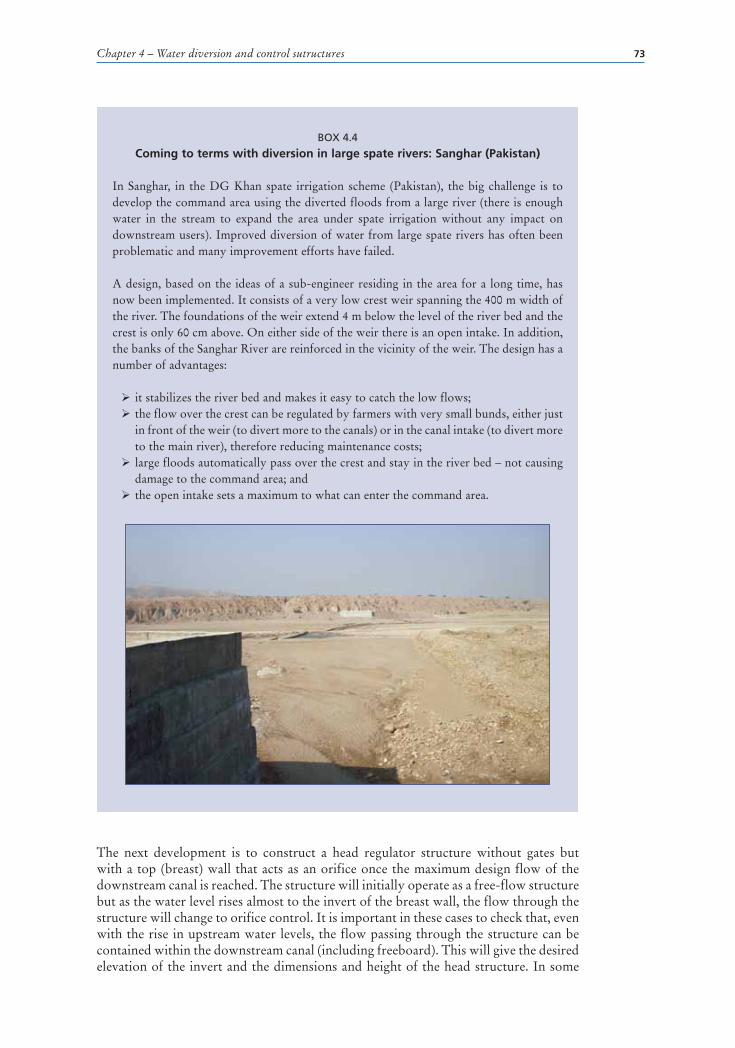
Chapter 4 – Water diversion and control sutructures 73
The next development is to construct a head regulator structure without gates but with a top (breast) wall that acts as an orifice once the maximum design flow of the downstream canal is reached. The structure will initially operate as a free-flow structure but as the water level rises almost to the invert of the breast wall, the flow through the structure will change to orifice control. It is important in these cases to check that, even with the rise in upstream water levels, the flow passing through the structure can be contained within the downstream canal (including freeboard). This will give the desired elevation of the invert and the dimensions and height of the head structure. In some
BOX 4.4
Coming to terms with diversion in large spate rivers: Sanghar (Pakistan)
In Sanghar, in the DG Khan spate irrigation scheme (Pakistan), the big challenge is to develop the command area using the diverted floods from a large river (there is enough water in the stream to expand the area under spate irrigation without any impact on downstream users). Improved diversion of water from large spate rivers has often been problematic and many improvement efforts have failed.
A design, based on the ideas of a sub-engineer residing in the area for a long time, has now been implemented. It consists of a very low crest weir spanning the 400 m width of the river. The foundations of the weir extend 4 m below the level of the river bed and the crest is only 60 cm above. On either side of the weir there is an open intake. In addition, the banks of the Sanghar River are reinforced in the vicinity of the weir. The design has a number of advantages:
� it stabilizes the river bed and makes it easy to catch the low flows; � the flow over the crest can be regulated by farmers with very small bunds, either just in front of the weir (to divert more to the canals) or in the canal intake (to divert more to the main river), therefore reducing maintenance costs;
� large floods automatically pass over the crest and stay in the river bed – not causing damage to the command area; and
� the open intake sets a maximum to what can enter the command area.

Guidelines on spate irrigation74
cases, where rising wadi bed levels are anticipated, or downstream irrigated land levels are expected to rise through sediment accumulations, the structure can be improved by providing concrete or steel stop logs for both the invert and soffit of the entrance, so that these can be removed or added to compensate for changing levels. Breast walls and high abutments are most needed when the wadi channel is confined and flood elevations are high. Gated intakes and rejection spillways located upstream from the head structure, in the case of approach channels to the intakes, and downstream, for gated weir intakes, provide further levels of protection.
Basic gated intakesGated intakes provide a capability to regulate the flow into a canal and can be considered where improved, more durable diversions such as weirs are used. The gates should be as wide as possible considering the intake requirements. The response time for the operation of the gates should be less than the time to flood peak (less than 10-30 minutes). Manual operation is usually too slow; electrical operation relies on power, which is often not available at key moments; hydraulically operated gates are the preferred option as they are quick and easy to operate. For this very reason, in Wadi Mawr, the manual operation is being replaced with hydraulic operation. If manual operation is the only available option, high-gain gears must be included to ensure adequately fast gate operation. In general, vertical lift gates wider than 2 m are not suitable for manual operation. All gates should be provided with large trash diverters/excluders that will trap the very large transported items such as trees, but not restrict flow to the intakes. These should be located upstream from the intakes, where possible, to guide large debris over the main diversion weir sections or around the diversion bunds or spurs, to ensure that no blockage of the intake or loss of water for the farmers occur. Easy access for machinery to these structures must be provided to assist with regular maintenance.
Openings for sluice gates should be as wide as possible to avoid accumulation of debris, since any blockage will cause a critical loss of water for the farmers. Gate design must be carefully considered, with the technical merits of radial and vertical gates balanced against ease of operation and capital costs. Vertical gates can normally be manufactured locally at lower costs than radial gates and are easier to install. However, they are constrained by the amount of lifting effort needed and must be provided with stop logs so that they can be sealed effectively in an emergency or for maintenance purposes.
As a safety feature, and on the assumption that gates may be left open when excessive floods occur, the gated opening must be designed to operate as an orifice as described for enhanced local intakes above. If the breast wall is set too low, it will reduce the actual flows that can enter the intake. For example, in the case of the Barquqa diversion weir and intake on the Wadi Siham in Yemen, the breast wall was set too low so that the stated design flow (5 m3/s for 3 700 ha) could not be achieved. This resulted in the reduction of the command area served to 1 700 ha and an additional new weir (Dabaishia weir) and new main canal had to be built further downstream to supply some of the land omitted. It is essential therefore that intake flows are related to command areas and downstream main canal capacities and that resultant specific discharges (l/s/ha) are checked against design norms. Hydraulic calculations for free flow and submerged flow are also needed to cross-check the elevation of the breast wall and intake size.
Operational guidelines sometimes recommend that canal intake gates be closed during large flood peaks to prevent damage to the main canal and to exclude water carrying very high sediment loads. However, as this represents lost water to them, farmers are

Chapter 4 – Water diversion and control sutructures 75
usually reluctant to accept any closure, especially on the rising flood limb, until the flood flows start passing over the diversion weir. In addition, operation of gates during high floods may be dangerous and impracticable. It is therefore unwise for designers to assume that gates will be closed during large floods and they should include assumptions for flow restriction using orifice control.
Gated intakes are obviously more expensive than un-gated structures and should have a long working life. A clear and effective maintenance programme must be worked out with the operating organization and designs must also comprehend any predicted changes in upstream or downstream elevations in both the canal and the wadi. Where necessary, downstream drop structures can be included on the main canal below the intake, although they are not normally necessary as spate canals are often characterized by relatively steep slopes. If drop structures are provided, it is important to consider ‘stepped’ drop structures, with the force of the water broken on a cascade of small steps. For spate systems in the flatter areas and in the upstream parts of spate systems, these may be needed to ensure that command levels over the land can be effectively maintained over time. As time passes, the drop will progressively reduce as the fields and the canal beds rise with increased siltation. Construction of these more permanent structures should use locally available materials and skills wherever possible. Preference should be given to equipment that is manufactured within the country and for which spare parts are available locally. This is particularly important for smaller works to be implemented by farmers and to ensure farmer-driven replication.
Walls of masonry, mass concrete (using selected and graded wadi bed material where suitable) or concrete blocks or stonework (ashlar) (if local block production capacity exists) may be preferable to reinforced concrete, as they are normally less expensive and require a lower level of setting out and construction skills. The most cost-effective construction materials will depend on site location, especially distance from the mountains and access to appropriate quarry sites. Masonry may prove to be the cheapest solution close to the foothills but mass concrete will be preferred where sand and gravel are easily available and larger stones are scarce. Such considerations and design/cost options must be carefully examined and discussed in detail with farmers during project preparation. Final designs need to consider that structures should resemble those that farmers consider suitable and successful.
Rejection spillwaysWith improved and more durable intakes, it is important to restrict flows diverted to canals to the design capacity of the downstream main canal, with allowances for freeboard. Rejection of excess flow either upstream or downstream from the head regulator/intake is an important safety measure that does not make significant increases to the overall costs. A rejection capacity is normally designed as a side spillway in the first part of the main canal system, where water can easily return to the wadi. The spillway needs to be designed as a lateral-flow weir capable of passing all the flow in excess of the downstream canal capacity. The spillway is more effective if a further flow control structure is provided on the canal just downstream of the spillway, so that water-level changes at the structure become more sensitive to excess flow than is the case in an open trapezoidal channel. An orifice control is the most effective means of increasing rejection, with the soffit of the orifice determined in relation to spillway crest level and deriving from the free-flow/orifice-flow hydraulic calculations. Rejection spillways and breach sections of canals are not new to farmers as this has been their means of flow control in traditional systems using indigenous resources and knowledge (see Figure 4.12).

Guidelines on spate irrigation76
New permanent diversion structuresA typical diversion structure includes a raised weir, with or without a fuse plug, a scour or under-sluice, a canal head regulator and a guide or divide wall. In the case of new permanent structures, an important decision relates to the choice between single or multiple intakes along the wadi to serve existing spate schemes and the location in the wadi. These different elements of design are discussed below.
WeirsIn perennial rivers, raised weirs are needed both to provide command and to divert the required amount of water into the intakes. In spate areas the land and wadi slopes are steep, and a high weir is not usually needed to achieve command. Moving an intake a short distance upstream, at the expense of a
short additional length of canal, can provide the extra command needed more cheaply. The temptation to command 100 percent of the area when suitable weir sites are limited should be avoided, as the last 3–5 percent of command can often increase the costs by 20–30 percent. There are several reasons to use a weir: (i) to stabilize the supply water levels necessary in wadis where changes in bed levels in response to floods can be frequent, (ii) to control the longitudinal slope of the wadi, which can vary significantly owing to sediment deposition and scour resulting from wide variations in size and duration of flood flows, (iii) to control the direction of wadi flow and thereby reduce local stream bank erosion, and (iv) to provide the head difference needed to operate a scour sluice.
The weirs on some spate diversion structures are constructed with a mild cross fall along the crest towards the canal intake. This has been found to be effective in the spate irrigation systems in Yemen as they encourage the deep-water channel to flow adjacent to the canal intake. Some examples from the Yemen are given in Table 4.3.
In many countries, particularly in recent times in Eritrea, the thinking seems to be that spate irrigation is something very simple and easy, and that therefore supporting designs and calculations for structures such as weirs, spillways and stilling basins are not needed or can be estimated without detailed designs. This has resulted in many failures. It is important to reiterate that whether the new system is complicated or simple, sound designs and calculations are still required. In fact, given the unpredictable nature of
FIGURE 4.12Side spillway constructed by
farmers in Wadi Rima in Yemen
TABLE 4.3Weir cross fall – examples from Yemen
Site Weir cross fall Note
Wadi Bana 1 in 400 Proposed for diversion weirs
Wadi Mawr 1 in 120 One-quarter of weirs at the intake side has the sloping crest
Wadi Rima 1 in 70 Diversion weir
Wadi Rima 1 in 33 Gabion bed sill, set at natural wadi cross slope at a bend

Chapter 4 – Water diversion and control sutructures 77
floods, proper design of weirs is even more important in spate than in conventional irrigation systems. The following paragraphs discuss the most important design and construction considerations.
Stilling basins are provided downstream from weirs to dissipate energy and to reduce the scouring effect of high-velocity flows. Inadequate or poorly designed energy dissipation will cause hydraulic jumps to form outside the protected area of a structure and result in both longitudinal and lateral erosion and damage. Any weir structure, whether improved traditional or of modern design, requires supporting hydraulic and stability calculations that cover (i) seepage through and around the structure, (ii) length, elevations and widths of stilling basin and energy dissipation measures, (iii) stability calculations for sliding and overturning, and (iv) estimates of longitudinal energy loss down the canal system. Without these calculations, it is likely that the structure will fail and that the whole spate irrigation system will be put into jeopardy.
The cost of overall weir and related structures and associated energy dissipation arrangements increases with specific discharge (flow/unit width) and height over the weir and hence head loss across the structure. In many cases, the most critical design condition does not occur at maximum design flow when downstream water depths are high and hydraulic jumps are drowned out. The critical conditions occur between low and maximum flow before full downstream water depths are achieved. It is thus important that calculations are completed for a range of discharges. The general recommendation is: avoid high specific discharges and large head drops but adopt sufficient head to achieve effective sluicing and to maintain command over the area to be irrigated.
In designing and constructing weirs or bed bars, care has to be taken not to interfere with the subsurface flows in the gravel of the wadi bed. These are one of the main sources of recharge to wells for drinking water in the neighbouring areas and supplementary irrigation downstream from the weir site. There are several instances where the weir was built on the bedrock, which effectively blocked all subsurface flow downstream of the weir. This effect has been observed in several of the modernized systems in the Tihama, particularly Wadi Mawr and Wadi Siham, and has caused considerable hardship for those living downstream of this new infrastructure. Weepholes and pipe tunnels in these structures will avoid such unexpected outcomes.
One important aspect overlooked in the development of new or improved weirs for spate irrigation is the failure to establish means for measurement of each flood flow at the weir sites. Weir structures provide perfect control sections and sites for easy flow measurement and local operators can easily be trained in appropriate data collection. It is most important to gather more data on actual flood flows that pass the weir sites, to increase knowledge of flood sizes (volume of flow, peak flow), frequency and duration, to confirm design assumptions and to improve upon design concepts for other newer structures.
Fuse plugsThe integration of a breaching section, or fuse plug, in spate diversion structures has a long history and has been applied in Yemen, Tunisia, Eritrea and Pakistan. Flood frequency analyses are often based on limited hydrology data and are often little more than intelligent guesswork. In addition, flood frequency distribution in arid regions is usually highly skewed, with extremely high events occurring at a frequency of 4–5 years. Incorporating a fuse plug will protect permanent weir and intake structures in the event that a much larger flood than predicted occurs. It also enables the width and

Guidelines on spate irrigation78
cost of a permanent weir to be reduced whilst design return periods are maintained. Farmers who are not familiar with the concept or have had bad experiences, for example in Sheeb in Eritrea, do not like the approach, particularly when they consider that the weir is breached too frequently, with the consequent loss of valuable irrigation water. In all spate systems, farmers want to extract as much of the wadi flows as possible as they are never sure when the next flow will come and how big it will be. What designers have to ensure is that after construction of the new weir and intake, farmers will still be able to divert at least the same amount of wadi floods onto their traditionally irrigated lands as before. The return period of breaking the fuse plug must be calculated carefully. It must be long enough to ensure farmers keep the benefits of the permanent structure it protects (i.e. no need for frequent reconstruction), but at the same time, the protective role played by the fuse plug in extreme floods should be maintained. A careful analysis of flood frequency distribution may help identify breaking points in return periods beyond which floods become much larger. In many places, this corresponds to a return period of 4 to 5 years.
If fuse plugs fail too frequently, farmers will take steps to reduce the labour needed for re-construction and increase the size of the breaching bund, thereby perhaps endangering all the improved structures at the site. In Chandia, Pakistan, for example, the fuse plug has been covered with concrete and, although this will certainly reduce the need for frequent re-construction, it will inevitably be breached in a more catastrophic manner, creating large scour holes and serious damage to the intake structure and weir, that is likely to have been overtopped and perhaps also to have failed.
The probability that one or more flood events with a specified return period will occur over the design life off a structure is shown in Figure 4.13.
FIGURE 4.13Probability that floods with specified return periods will be encountered
2
2 5 10 20
Design life, Tn : (years)
Ret
urn
per
iod
T Pf
: (y
ears
)
Pro
bab
ility
P:
(per
cen
t)
5
10
20
50
100
200
500
1000
2000
5000
50
1
100 200
6350
25
10
5

Chapter 4 – Water diversion and control sutructures 79
For example, if a fuse plug is designed to fail at a discharge with a ten-year return period, then there is a 63 percent probability of one or more floods of this magnitude occurring over the design life. However, there is an appreciable probability that much larger floods will occur, for example, a 10 percent probability of a flood with a 1-in-100-year return period.
In the absence of reliable flow records, it may be necessary to adopt a flexible approach, choosing an initial conservative design (this may cause frequent breakings in the first year or two) and then adjusting the length and shape of the breaching section as experience is gained.
Scour sluiceWadis transport very large concentrations of fine sands, silts and clays. These cannot be excluded from canal networks at an intake and should therefore be kept in suspension and transported to the irrigated fields. However, the coarser sediments will settle in canal head reaches, eventually reducing the discharge capacity of the intake. The first step in minimizing such problems is to exclude as much of the coarser sediment as possible at the intake and then to ensure that any sediment that enters the canal system in suspension is not deposited until it reaches the irrigated field. This is achieved by diverting the bed load material transported in flood peaks past the canal intake, via a scour sluice, and by ensuring that the sill level of the sluiceway is set below the canal invert at its entrance. In addition, overshot structures on the canal systems need to be avoided and a constant and sufficiently high flow velocity maintained within the canal network.
The shape and discharge capacity of scour sluices have been the subject of numerous experiments. The curved channel sediment excluder (see Figure 4.14), has been used in several improved large spate irrigation intakes. This type of intake and sluice arrangement was developed to improve sediment exclusion in floods, by utilizing the beneficial effects mentioned earlier of a channel bend in excluding coarse sediment. An artificial bend is created in a short converging channel constructed upstream from the sluice gates. The canal intake is located on the outer side of the artificial bend, angled at about 30o with a small diversion angle. The sluicing capacity is set at around 30 percent of the canal design discharge. Providing an excessive sluicing capacity is self-defeating, as it will induce very high velocities in the flows approaching the intake, which will pick up additional coarse sediments, some of which will be thrown into suspension and diverted to the canal. In addition, farmers are unlikely to agree that an excessive volume of water be used for this purpose, as they will regard it as lost to their irrigation system (as discussed earlier).
The design and operation of scour sluices for spate schemes have important differences from the practices described in irrigation engineering textbooks and design guides based on perennial irrigation diversion practice. In particular the ‘still pond’ method of operation, frequently used at intakes in perennial rivers, is not applicable in wadis. Long divide walls, separating flows in the sluiceway from those passing over the weir, and projecting some distance upstream from the weir are not used in spate intakes, where the weir is usually sited upstream from the intake and sluice gates.
Operation of the sluice gate often poses problems. In practice, manual operation of sluice gates in rapidly varying spate flows, so as to follow idealized gate operation rules, has proved difficult or impossible. On the assumption that the structure is staffed when a flood arrives, the flood peak will often have passed the intake before the sluice gates can be fully opened. Apart from these practical difficulties, the first priority of farmers is to divert as much water as possible. They may be extremely reluctant to open sluice gates,

Guidelines on spate irrigation80
except during the largest floods, when high flows diverted to a canal threaten to damage canals and water distribution structures. Thus, unless the water supplied via the sluice is needed for downstream diversions, frequent operation of sluices in farmer-managed systems cannot be assumed. Experience from large ‘new’ intakes in Yemen suggests that sluice gates should be constructed without a headwall, to improve the throughput of sediment and trash. The sluice gate in this case must be capable of being raised above the maximum expected high flood water level and designed to withstand the forces that would occur if the gate was left lowered and was overtopped in large floods.
Canal head regulatorsHead regulators are designed to pass the canal full supply discharge when the water level in the wadi is at weir crest level. In spate intakes the width of the head regulator opening is usually kept approximately the same as the bed width of the downstream canal.
Head regulators in conventional river intakes are frequently aligned with the gates at 90° to the weir axis, but this requires flows entering the canal to turn through a large angle, which is far from ideal for sediment control. Much smaller diversion angles are recommended when sluicing during flood peaks is envisaged (see example in Figure 4.14).
FIGURE 4.14Layout of a typical curved channel sediment excluder
Sluice flow
Sluice channel
3-5m sluice gates
Curved channel
Crest of diversion weir
Skimming weir
Canal flow
91-1
91-35
92-15
Guidepier
93-10

Chapter 4 – Water diversion and control sutructures 81
The discharge capacity required at intakes (and for canals) in spate schemes is much larger per unit area served than would be the case for intakes in perennial rivers, as the objective is to divert the maximum possible amount of water to the fields during the short time periods when spate flows occur. Values based on intake design discharges and nominal command areas in existing improved systems range between 2 and 28 l/s/ha or more and depend on the discharge characteristics (hydrographs) of the wadis and the catchment areas rather than on crop water requirements. The low figure quoted above is for Wadi Rima in Yemen, where a large proportion of the annual discharge occurs as perennial base flows and low flood recession flows. The more typical higher figure is for an intake on the Wadi Mai Ule system in Eritrea, where most of the annual runoff occurs as very short spate flood events and where the catchment is compact. The latter intake capacity is regarded as low compared to the Eritrean MOA current practice and farmers complain that the intake is too small (Anderson, 2006). The discharge capacity/unit area provided for intakes serving the three canal groups in Wadi Zabid in Yemen was 12.9, 15.5 and 40 l/s/ha, increasing down the wadi to reflect the reducing probabilities of receiving water. In Wadi Mawr in Yemen, a capacity of 21 l/s/ha was provided.
Discharge capacities obviously have to be selected taking account of the distribution of flows within the annual hydrograph, the duration of, and discharge variations during, flood events, and the soil characteristics (water-holding capacity) of the areas to be irrigated, rather than being based on crop water requirements. Simulation modelling, using representative flood sequences, has been used in larger schemes to ensure that a sufficient intake capacity is provided. In smaller modernization projects, where neither the data nor the expertise to carry out such studies may be available, the combined diversion capacity of existing traditional intakes can be used as a guide to the intake capacity that will be expected by farmers.
Single versus multiple intakeDiversion of spate flows in traditional systems is usually carried out at many locations along a wadi. Multiple intakes provide an effective solution when the cost of each diversion structure is low and each diversion supplies a relatively small canal system with manageable flows. When substantial improvements to diversion arrangements are envisaged, the practice in the past has been to provide a limited number of major diversion structures, often only one, serving large new canals that connect into and traverse the existing traditional canal network.
A major disadvantage of the single new intake approach is that it gives the upstream users control over diversion of a larger proportion of the annual flows, which in turn leads to an increase in the inequity between upstream and downstream users’ access to water. This has often been a result of the way that systems are being operated in response to pressures from powerful local interests, rather than to inherent technical deficiencies in the water distribution arrangements. An equitable distribution of flows would have been possible in some of these upgraded systems if larger intake capacities had been provided. Although this might have required a change to water rights rules based on volumetric allocations and to operation by strong farmer groups or operating agencies that were able to enforce an equitable water distribution, these were not feasible in many of the systems modernized over the last 20–30 years. In Wadi Mawr in Yemen, for example, a sophisticated system was devised for dividing flows but was never used, as the farmers did not understand it and the water user associations (WUAs) were not properly involved from the start. The net result was that upstream users controlled all the water that could enter the system, and users in the middle and end parts of the command area did not receive sufficient water. Similarly, in some of the new spate systems in East Harrarghe in Ethiopia, downstream farmers have abandoned

Guidelines on spate irrigation82
newly constructed systems and have reverted back to having independent downstream offtakes which give them more flexible control of water. There are many examples of farmers who own land commanded by the ‘improved’ systems but who do not receive enough water and have to reactivate their traditional intakes, in order to capture the flood flows that pass over the weirs of a new single permanent diversion.
In several spate irrigation intake and diversion improvement works, conventional economic analyses have been used to reach what are considered cost-effective designs and this has resulted in a diversion capacity for new intakes that is less than the combined capacity of the traditional intakes. This is the overriding problem in Wadi Siham in Yemen and Wadi Laba, Eritrea, where all such intakes are insufficient to meet the requirements of the previously commanded areas. It would appear that the designers did not comprehend the traditional means for sizing intakes or, if they did, it was not made clear to farmers and local authorities that only part of the previously commanded and irrigated area would continue to be irrigated under the new intake system. If a wadi approach had been used, relating existing and planned command areas, deficiencies in water supply would have been identified and some traditional intakes and canals retained to supply the omitted areas. Not only were some areas excluded, but the designs for the main canal cut off the traditional intakes and made them unusable. In Wadi Zabid, this constraint was recognized and the designs adopted comprise a number of separate intakes built from gabions and based on the traditional locations and design duties (15 l/s/ha to about 60 l/s/ha).
A close examination of spate systems that have numerous self-contained intakes and associated canals reveals that consolidation into a system supplied by one single diversion is not advantageous. Some rationalization may be essential if the number of independent diversion structures is to be reduced to provide better engineered and more durable replacements, and such an approach could then more closely replicate the traditional systems that they are to replace. Three examples of new permanent intakes with differing levels of sophistication and cost are described below.
Example 1: New permanent intakes in Wadi Rima in YemenA new single diversion weir and intake was constructed on this wadi in the late 1980s at the upstream end of the spate-irrigated area close to the foothills and near to the site of the most upstream of the existing traditional intakes (Oosterman, 1987). At the diversion site, the natural wadi width was constrained by rock outcrops and was fairly narrow, thereby providing a good site for a permanent weir structure. The intake consists of a raised weir, a single right bank canal intake and a low-level sluiceway located near to the intake (see Figure 4.15). The main canal supplied by the intake follows the high terrace on the north side of the wadi, passing water to the few traditional canals where it crosses them. Just before the start of the main flood plain and irrigated areas, the main canal divides into two, with the right branch designed to take one-third of the flow and the left branch the remainder by means of a siphon under the wadi.
The new system replaced a traditional spate system with many intakes along the wadi, with rotation between canals of base and low flood flows diverted at a single point at the head of the wadi. Its main technical features are (see Figure 4.16):
� A relatively high weir was provided to obtain the head needed for effective hydraulic sediment flushing. The 70 m long weir is constructed from mass concrete with a protective layer of stone to resist abrasion from the cobbles and boulders that pass over the weir in spates. The weir crest slopes down towards the canal intake, with a drop of 1 m across the weir crest, to encourage the low-flow channel to flow towards the canal. A short submerged bucket-type stilling basin was used.

Chapter 4 – Water diversion and control sutructures 83
� The gated under-sluice was designed to pass the lower, heavily sediment-laden layers of the approaching flows through the structure during floods. The sluiceway was originally intended to operate automatically in floods, but trash accumulations and deposits of fine sediments in the small openings that formed part of the hydraulic actuation system prevented the original system from functioning. The sluice gates are operated manually during floods. Initially trash blocked the intake, so a trash screen consisting of vertical steel pipes and horizontal steel cables has been constructed in front of the intake to divert trash over the weir.
� A gated canal intake is aligned with the approaching flow direction, supplying the main canal via a short settling basin designed to trap the coarse sediments before
� they enter the main canal. The settling basin can be flushed to return trapped coarse sediment to the wadi.
� The layout of the north side of the intake showing the under-sluice, canal intake, sediment-settling basin and sediment-flushing arrangements is shown below (Oosterman, 1987).
� Soon after completion, disputes arose between the north and south bank canals over water allocations and this resulted in a high-level political decision that awarded equal allocations to both canals (intake design duty was 1.5 l/s/ha). Only two-thirds of the original design area of 10 000 ha could therefore be supplied with irrigation water from the new intake. The south canal thus receives far too little water for the command area and has made necessary the construction of two new intakes and the revival of the former traditional canal systems.
Following problems with trash encountered during initial operation, a trash deflector was constructed from steel pipes and cables to deflect trash away from the canal intake and towards the sluiceway (see Figure 4.17). With this experience, the designers recommended that future similar structures should use a wide scour sluice, at least 5 m wide, built without a breast wall to allow large trash to pass through the sluice.
FIGURE 4.15Wadi Rima spate irrigation intake, Yemen

Guidelines on spate irrigation84
Example 2: New permanent intake in Wadi Laba, EritreaA new intake was constructed to supply a traditional spate irrigation system in Wadi Laba located on the Eritrean Red Sea coastal plain. The design of the new intake profited from the experience gained in Yemen and from the earlier farmer-operated spate improvement projects in Pakistan. It was originally intended for farmer operation. The diversion structure viewed from upstream is shown in Figure 4.18.
FIGURE 4.17Trash deflector, Wadi Rima intake (2003)
FIGURE 4.16Plan of Wadi Rima intake and sediment-settling basin
wadi rima
plan of intake, sediment trap and sediement ejector
longitudinal section
undersluice
weir
sediment (sand and gravel) trap 6 m
emergency spillwaydrop structurewith orifice
sedimentejector
spill
canal
sediment depositradialgate
radialgate
intake
under-sluice
weir crest
120 m
intake

Chapter 4 – Water diversion and control sutructures 85
The key features of the structure are: a) a canal intake incorporating a curved-channel sediment excluder; and b) a low-cost, short concrete weir, with a breaching section or fuse plug that connects the weir to the far bank. A short settling basin, designed to be excavated by bulldozer, was constructed in the canal head reach. This was intended to trap the gravels and coarse sands not excluded at the intake, particularly if it was operated in floods with sluice gates closed. A conduit near the canal head runs under the wadi to supply water from the main canal to the irrigated areas located on the opposite bank of the wadi.
In Figure 4.18, the canal intake gates and the gated curved-channel scour sluice are on the extreme left, the concrete weir is in the centre and the fuse plug extends from the end of the weir to the right-hand edge of the picture. The crest level of the fuse plug is higher than the design flood level at the weir end and reduces across the wadi, to ensure that the fuse plug washes out initially at the far bank.
The system was commissioned in the wet season in 2002, when a major flood, its peak discharge still being a matter of some dispute, washed out the fuse plug. This protected the weir and intake from serious damage, but as the fuse plug was not repaired for some months, water from the later floods could not be diverted and only a very small area was irrigated. Farmers regarded this as a serious failure of the new system, even though the fuse plug had functioned as its designers and project supervisors had intended.
An obvious lesson learned from this experience is that the implications of including a fuse plug in a diversion structure must be understood and, more importantly, agreed by the farmers or agency that will have to rebuild the plug when it fails. Robust arrangements must be in place to ensure that a fuse plug is rapidly reinstated following a breach. The fuse plug was repaired for the 2003 wet season and the new intake performed broadly as anticipated, stabilizing the wadi approach channels at the canal head, controlling the flows admitted to the canal and excluding large sediments from the canal head reach. The sluice was kept open as much as possible to provide water for downstream south-
FIGURE 4.18Spate diversion structure constructed at Wadi Laba in Eritrea

Guidelines on spate irrigation86
bank farmers, who were unhappy with the volumes of water supplied by the conduit. It did not prove to be possible to excavate the settling basin, as a bulldozer could not work on the wet unconsolidated sediments trapped in the basin, which rapidly silted up. Machines which can work from the bank are needed to excavate the settling basin mechanically. As a series of floods may occur within a few days, sediments often have to be removed when the canal is still flowing and before the sediment deposits can dry out.
While it is still a little early to draw firm conclusions from an intake and water distribution system requiring quite different operational skills to those needed for the traditional systems it replaces, Haile (2003) drew a number of useful conclusions based on the experience with the earlier traditional system and the first two years of operation of the new system. Many of these conclusions were concerned with institutional issues, particularly the need for more effective participation of farmers in the design and development of spate improvement projects. On the technical performance of the intake, Haile et al. (2003) reported that the operation of the intake structure, particularly the sluice gates, is problematical in very rapidly varying spate flows. This has been observed in many other spate schemes. Electrically powered gates can rarely be justified when conventional cost-benefit analysis is applied and are subject to power shortages. Haile et al. (2003) also reported that the diversion capacity provided at the new intake may be too small to irrigate the target command area, as the design area was not irrigated in 2003 although it was a year with very good floods
Example 3: Adurguyay intake in Gash Barka region in EritreaThe Adurguyay intake is a basic permanent intake constructed on a small ephemeral sand-bed river in the Gash Barka region in Eritrea, a region where spate irrigation is being introduced to provide water in areas that have relied in the past on rainfed cropping. The river is much smaller than the wadis considered in the earlier examples. The structure, as shown in Figure 4.19, includes the elements found in conventionally designed river intakes, i.e. a raised weir, a gated scour/sediment sluice and a gated canal intake, but suffers from many of the problems already identified relating to intake capacity, silt exclusion and blocking of entrances to intake and sluices by transported debris. It should be noted that smaller command areas require higher unit flows, about 80–100 l/s/ha, to get enough flow through the intake whilst the flood lasts (10–20 min)
Local engineers report that this structure functioned reasonably well, from the engineering viewpoint, in the first year that it was operated by farmers but they do not record the impact on annual maintenance costs for silt removal and the ability of the system to meet all the water needs of the downstream farmers. They report that in this area masonry or concrete-type weirs offer advantages over the gabion weirs with un-gated canals that they have used at similar sites in the past and can be constructed at similar cost. The technical problems of diverting water from ephemeral spate rivers reduce as the wadis and their flood peak discharges become smaller.
Location of intakeThe best location for a canal intake is on the outside of a relatively mild wadi bend, just downstream from the point of maximum curvature. At this location the deep-water channel is established at the outside of a bend during floods and this forms the low-flow channel during flood recessions. Locating an intake at the outside of a bend thus helps to ensure diversion of low flows. It also provides sediment control benefits at times of medium to large flood flows when a wadi is flowing at a reasonable depth over its full width. Secondary currents generated at a bend sweep coarse sediments that are transported on or near the channel bed towards the inside of the bend and away from the canal intake. This principle is also used at intakes with curved-channel sluiceways.

Chapter 4 – Water diversion and control sutructures 87
The disadvantage of locating an intake at the outside of a bend is that trash picked up by floods tends to concentrate at the outside of a bend and interferes with the intake. The problem is worst at very sharp bends. There are three basic options that can be combined for managing trash:
� encourage the trash to pass down the wadi through careful design; � detain the trash upstream of the intake, e.g. with a floating boom, where it will not significantly obstruct the flow; and
� design the canal intake so that (smaller) trash can pass through and into the canal.
The third option is usually the most attractive in cost terms although this requires effective and attentive system management. However, there is an upper limit to the size of trash that can be passed into a canal and, once something becomes trapped, then it will obstruct the passage of smaller trash so that a blockage follows.
Although adopted in some large spate systems, double-sided intakes, i.e. structures with canal intakes on both banks are not usually recommended. Ensuring that water flows to both sides of wide wadis, when the diversion weirs are silted to crest levels, usually requires active intervention in the wadi bed to construct channels or bunds. However where intakes exist on the left and right banks, these have often derived from traditional practice and systems and have allowed adequate flows to both sides through the presence of small islands or physical barriers that split the flows. In smaller wadis, basic diversion structures may have an essential role, particularly in areas where spate irrigation is being introduced to formerly rainfed areas and farmers do not have indigenous skills in diverting and distributing spate flows.
FIGURE 4.19Adurguyay intake, Eritrea

Guidelines on spate irrigation88
SPATE CANALS AND WATER CONTROL/DIVIDING STRUCTURESTraditional canals and water control structuresIn traditional spate systems, flows are diverted to short, steep canals. Large canals may split into two or more branches to reduce flood discharges to manageable flow rates, but there are usually no secondary or tertiary distribution systems. All the flow in a canal is diverted to a group of bunded fields by an earthen bund that blocks the canal. Water is passed from field to field until all the fields in command have been irrigated. The canal bund is then broken, and the process is repeated at a bund constructed further down the canal at the next diversion point. Once the bund is breached, the canal water level drops below the level of the field offtake, preventing further diversion until the bund can be rebuilt. The order in which fields are irrigated and the number and depths of irrigation are usually controlled by established water rights agreements (see Chapter 7 for details).
The objective is to divert the maximum possible amount of water to the fields in the shortest time periods, sometimes less than an hour. By avoiding constrictions in the system, this approach can also ensure that minimum deposition of silt occurs in the canal systems with most of it ending up on the fields. Canals in spate schemes thus need much larger capacities per unit area served than canals in perennial irrigation schemes.
The upstream reaches often resemble wide and shallow natural wadi channels, with beds formed from coarse sediments. The size of the bed sediments reduces rapidly in the downstream direction, and middle and lower reaches typically have sand beds. The lower reaches of established canals may have stable armoured beds and flow between well established banks that are protected from high water velocities by natural vegetation.
Traditional canals in spate schemes are often constructed without drop structures and are far steeper than conventional canals used in perennial irrigation systems (see Box 4.5). Gates are not used and control of flows is carried out through proportional dividers and farmer management. Particularly where the area is flat, ‘soft’ and sandy – as in the DI Khan, DG Khan and Kacchi in Pakistan – care is taken to guide the water over a large area, to avoid the erosive effect that comes with too steep slopes. However, some traditional canals feature different types of water control structures, ranging from the simple earthen bunds used to head up and divert water from a canal to a group of fields or divide flows, to drops and side spillways used to protect a downstream canal network against excessive flows or too high and erosive velocities.
Examples of traditional canal water control structures are described below. Figure 4.20 shows a traditional canal diversion bund in Wadi Zabid in Yemen in 1980 that has been breached to pass water further downstream. The bund diverts all the canal flow until the fields under command have been irrigated, with water usually being passed directly from field to field. The bund is then breached and water passed downstream to the next diversion point. Figure 4.21 shows a stepped drop structure that was developed by farmers and copied in large numbers in the Wadi Zabid system. The drop structures avoid uncontrolled flows that may otherwise lead to gullies and loss of soil moisture or may make it difficult to divert water downstream.
Improved traditional canals and water control structuresImproving traditional canals may include changes in canal design and the installation of new or improved water control structures. Such structures can be clustered in five groups: check and drop structures, flow-splitting structures, flow spreaders, field offtakes and in-field structures. Many of the water control structures used in improved spate systems are similar to those used in conventional perennial irrigation practice.

Chapter 4 – Water diversion and control sutructures 89
FIGURE 4.20Traditional canal diversion bund, Wadi Zabid, Yemen
FIGURE 4.21Stepped drop structure, Wadi Zabid, Yemen

Guidelines on spate irrigation90
There are, however, important additional features that have to be considered in spate schemes:
� A canal network will already be in place when existing spate schemes are being improved. Improved canal networks, supplying water to controlled field outlets, can give better control and overcome some of the other disadvantages of the field-to-field water distribution system, but will probably also require a change in the way that water is distributed. This could have a great impact on existing water rights and rules and needs to be negotiated with farmers in the design phase.
� Any improved system must ensure that irrigation can be carried out quickly, in the short periods when spate flows occur. Experience suggests that major modifications to canal systems of farmer-managed schemes should not be considered unless there is significant siltation, scour or canal-breaching problems, or farmers request improvements. Improvements should be developed with the farmers to ensure that they understand and agree with any implied changes to
BOX 4.5
Traditional canal slopes: the example of Wadi Zabid, Yemen
Traditional canals usually follow the prevailing land slope and rarely incorporate the drop structures used in conventional canal systems to reduce flow velocities. High slopes provide the high velocities needed to convey very high sediment loads, and traditional canals rarely suffer from the excessive sedimentation problems observed in the canals of some modernized spate systems. This is because the velocities are maintained high throughout the system, a situation of torrential flow where the inertial forces dominate over gravity forces (Froude number >1). Abrupt changes in direction are avoided as are sudden reductions in velocity of flow at closed structures. Although quite high flow velocities are generated, canals do not seem to suffer from widespread scour problems. This is probably because bed materials are much coarser and erosion-resistant and the high rates of scour are balanced by the very large incoming sediment loads.
Bed slopes of traditional canals in the original (before modernization) Wadi Zabid system in Yemen are reported by FAO/UNDP (1987) and presented below:
The canal slopes are about half of the slope of the Wadi Zabid bed at the upstream diversion site, and are much steeper than the canals in the modernized system, which were designed with a slope of around 1 m per km or less. The modernized canals rapidly silted up and needed frequent desilting to maintain discharge capacities. They were designed based on conventional thinking on maximum permissible velocity in earth canals which is too low for spate irrigation canals.
Canal Maximum capacity (m3/s)
Average bed slope (m/km)
Mansury 40 3.8
Rayyan 60 3.7
Bagr 40 3.7
Gerhazi 50 3.9
Mawi 60 4.8

Chapter 4 – Water diversion and control sutructures 91
water distribution. The unpredictability and speed of spate flows call for simple water control rules that avoid any complex canal operation. In particular, the use of gated structures, either at the intake or in canals, must be decided with clear understanding of management implications, as spate flows usually occur at short notice and often do not give farmers sufficient time to operate the gates.
� In existing schemes, where canals are performing reasonably satisfactorily, the design of new or extended canals should be based on the slopes and cross-sections of existing traditional canals, derived from surveys. If the discharge capacity is to be changed, then the survey data can be used to select a canal design method that best mimics the existing canal slopes and dimensions. The selected method can then be applied to design the new canals. Any modifications must ensure that the high sediment-transporting capacity is maintained through the canal network.
� It is important to note that conventional ‘regime’ canal design methods were developed for canals in perennial irrigation systems that are operated within a fairly narrow range of discharges and have a small sediment input. This contrasts with the situation in spate canals, where discharge varies rapidly over the full range of flows from zero to the maximum discharge. Sediment inputs are very large and canal designers are not free to set the canal cross-section and slope to carry the required discharge without also providing an appropriately high sediment-transporting capacity. This rules out the use of most conventional canal design procedures.
Canal designThe Simons, Albertson and Chang canal design equations and methods are adapted to situations of high sediment loads seen in traditional spate canals (Lawrence, 2009). These methods have been successfully used to design new canals in spate systems. Computations with these methods can be carried out using HR Wallingford’s SHARC sediment management software that can be found at: http://www.dfid-kar-waki.net/w5outputs/software.html.
In conventional irrigation, the peak or design discharge is used to determine the canal bed slopes and cross-sections. Following this approach for spate canals will result in serious siltation problems at lower flows. This is because spate canals flow at their full design discharge for very short periods of time. Most of the time the canal flow is much lower than the peak discharge and a steeper canal bed slope than that set by the maximum flow is required to avoid sediment deposition. As a rule of thumb, about 70 percent of the peak discharge could be used to determine the slope and width of spate canals when one of the canal design methods mentioned above is used. The capacity to convey the maximum discharge is then provided by increasing the depth and freeboard. There may be some erosion of the canal bed and banks when the flow in the canal is large but, as very high flows are maintained for short periods and will be carrying very high sediment loads, there is little chance of serious scour problems occurring.
Check and drop structuresWhile diversion from canals by a series of earth embankments (bunds) is a simple system, bund reconstruction is difficult while there is water in a canal and the recurrent effort of rebuilding the embankments is labour-intensive. Farmers often request better control structures when schemes are being improved.
One option is to provide an intermediate design of combined check/drop structure. This comprises a basic drop structure, combined with an earthen embankment for heading up the flow to redirect it onto a series of fields. This type of structure is often observed in the more mature traditional systems, when there are substantial drops between fields. The earth embankment should not be constructed within the structure, where there is a

Guidelines on spate irrigation92
significant risk of seepage failure at the interface, but should be built upstream. The use of an earth embankment keeps the operation similar to the situation of an embankment without a structure. Provision of gates makes operation simpler and eliminates the need to reconstruct bunds after each flood but runs the risk of sediment deposits.
The primary function of this type of structure is to limit the scour hole that forms when an embankment is breached. This scour hole, unless excessively large, will generally fill up with sediment when flows into the canal decline and finish. Drops usually have simple stilling basins protected by placed stones and broad crests that can be raised to reflect progressive changes in command levels within the overall system.
When more conventional gated or combined drop/check structures are adopted for spate schemes, the following issues need to be considered:
� If the traditional water distribution practice is unchanged, then each structure along the canal will, in turn, receive the full canal flow (except for losses). All structures have to be designed for the maximum canal discharge.
� Gates are relatively expensive and generally not preferred as they permit abuse of water rights and can encourage siltation if not operated effectively. Stop logs are much cheaper, but are not recommended as they are difficult – usually impossible – to remove during spate flows and provide overflow rather than undershot control. Perhaps a better alternative is proportional flow division, which is the traditional approach in most systems with open or undershot flow.
� It is necessary to ensure that the upstream water level is below any offtakes when a structure is open to allow one-directional flow down the canal.
� It is important to know whether the structure is required to raise the upstream water level in the canal to achieve adequate command of the land.
� Where gated controls are provided, additional measures for passing excess flows must be considered, in the (likely) event that spate flows in the canal arrive when the structure is closed. (Can excess water safely spill over the upstream banks or does the structure need to include spill capacity?)
An upstream view of a combined gated check and drop structure designed and constructed by local Yemeni experts is shown in Figure 4.22. This is a good structure from the design point of view but the figure shows lack of operational understanding. The structure is meant to be an on-off system, which implies that both gates should not be closed at the same time, as they are shown to be in the figure.
There will be a need for downstream energy dissipation measures when a structure incorporates a drop to raise upstream water levels to gain command of the land. This is also true when excess flow is allowed to spill over the structure or jet flow is allowed to occur under a partly open gate. In conventional systems, a depressed stilling basin is used to dissipate this energy safely. Conventional stilling basins can add another third to the capital cost of structures but will reduce the annual maintenance needs and expenditures. This cost can be reduced by accepting some scour downstream of the structure, providing a shorter but depressed stilling basin, or no protection, but with side wall foundations deep enough to avoid undermining, and accepting temporary scour during periods of high flow.
Flow-splitting structuresFlow-splitting structures are provided on main or secondary canals where flows were traditionally divided proportionally between groups of farms or where it is necessary to reduce flood flows in canals to smaller, more manageable discharges. Division

Chapter 4 – Water diversion and control sutructures 93
structures are important and may be one of the most justifiable investments in spate scheme improvement projects. They are best if built from local materials, with the use of gabions or dry stone pitching, and designed in close consultation with farmers.
An example of improved flow splitting is the Mochiwal flow distribution structure built on Daraban Zam in DI Khan in Pakistan. At Mochiwal, the channel is split into two directions. The north channel feeds a lower-lying area of 500 ha, whereas the west channel feeds 3 000 ha. Before the intervention, the problem was that all the flood tended to go to the north area where it would create havoc and wash out all diversion structures while the west channel did not receive any water. The construction of a gated structure on the north channel made it possible to regulate the water distribution to the benefit of both sub-command areas.
One approach for splitting flow used in Eritrea was to provide a hardened flow division structure, constructed from gabions, that splits high flows into two channels and provides a durable hard point that farmers can use to anchor temporary diversion bunds, that can be adjusted from spate to spate to manage the distribution of lower flows. An example of such a structure constructed in Eritrea is shown in Figure 4.23.
Flow spreadersFlow spreaders are not very common but have been applied in Morocco at the tail of lined sections of flood channels. They are large triangular structures meant to spread flood water over a wide section at the end of the flood channel and avoid scour at a single point.
FIGURE 4.22Gated combined check/drop structure in Yemen

Guidelines on spate irrigation94
Field offtakesWhile some spate schemes have a recognizable canal system serving each field, field-to-field irrigation is usually practised. Under this system, the uppermost field receives the water first and it is allowed to pond to a pre-determined depth. When that depth is reached, the field bund is breached and the ponded water is released to the next field. Meanwhile, any incoming flow passes through the first field to the next one. This process is progressively repeated.
The main advantage of this system is that water is applied quickly at high flow rates, during the short time that spate flows occur. There is also no investment in, or land lost to, a separate canal system. Crops in upstream fields may be damaged if there is a flood when the downstream land is still entitled to water. Further, the lack of separate channels means that more water will percolate en route and less water will reach the downstream areas (an advantage for the upstream fields).
The normal upstream-first hierarchy for spate irrigation means that the flow capacity of field offtakes has to be sufficient to take the full incoming canal flow. Properly engineered large capacity offtakes are expensive. Open channel offtakes are less expensive than gated culverts. Whether offtakes need gates or other means of closing them will depend on the canal water level when any check structures on the canal are open.
In more conventional water distribution systems, where water is supplied to a number of field offtakes at the same time, there is still a requirement to provide large offtake capacities. Very substantial irrigation duties are required in spate schemes to supply water at the flow rates wanted by the farmers.
In-field structuresFields naturally form into a series of level terraces. There is, therefore, a difference in level between each field and the next one downstream. This difference increases over time as the upstream fields receive more water and sediment than the lower fields.
FIGURE 4.23Gabion flow bifurcation structure in Eritrea

Chapter 4 – Water diversion and control sutructures 95
Water flowing from one field to the next causes erosion, the extent of which depends on the drop, the flow and soil conditions. In many cases, farmers place boulders where excessive erosion occurs, and more permanent drop structures between fields may be needed. An example of a gated field water distribution structure used in a modernizedspate system in Yemen is shown in Figure 4.24.
The importance of such field-to-field systems should not be underestimated and they represent a major improvement in water productivity. The reduction of downstream erosion avoids in-field gullying, which could lead to a dramatic depletion of soil moisture apart from the loss of irrigation to the downstream fields, since water moves without control from field to field.
A related structure is the field-inlet structure that has become popular in several areas in Pakistan where in many areas the field sizes are very large and surrounded by high bunds. The system is usually based on irrigation by a single flood event and water is applied sometimes at a depth of close to 1 m. This poses a problem not so much of letting water into the large bunded field but of preventing it from flowing out once the irrigation is over. To prevent this from happening, simple intake structures have been introduced with stoplogs which have gained popularity fast (see Chapter 5 for further details).
WADI BED RETROGRESSION AND WADI TRAININGWadi beds can be significantly lowered during the passage of large floods and it is not unusual for traditional intakes to be left stranded above the new scoured bed level, making it impossible to divert water into the canal system. The usual response is to relocate the intake or to extend a diversion spur further upstream to regain command. Where this is not possible, it is necessary to install one or more low check structures
FIGURE 4.24Gated field water distribution structure in a modernized spate system in Yemen

Guidelines on spate irrigation96
to trap sediments and raise the bed levels. It would usually be beyond the capacity of farmers to construct structures that span a wadi and are robust enough to survive spate flows.
Providing structures to control bed levels is an option but it is often difficult to justify in small spate schemes. The preferred material for bed sills is mass concrete, which can be cast into excavated trenches. Gabion bed sills have also been used, with mixed success: even when protected by a surface skin of concrete, they may have a very short life at upstream sites where boulders and cobbles are transported in floods (Lawrence, 1982). Bed stabilizers should be designed so as not to cut off all subsurface flow in the river bed and thus deprive downstream well-owners.
In Pakistan, where bulldozers are available to farmers at subsidized rates, some very large bunds have been constructed to regain command in degrading wadi sections. While the bunds may sometimes fail, this approach is often the most cost-effective option.
BANK PROTECTIONHigh flow velocities during spates often erode wadi banks, particularly in the meandering middle and lower reaches. The sinuous flow alignments within the wider wadi channel result in scouring and undercutting of wadi banks at the outer curves and sedimentation at the inner curves. This causes meander patterns to develop and migrate downstream. Bank erosion scours out valuable irrigated land and can threaten canals running parallel to the wadi banks. Both these processes can be seen in Figure 4.25 which shows the Wadi Rima in Yemen shortly after it emerges from the foothills into the flood plain.
FIGURE 4.25Bank cutting and the development of a meander, Wadi Rima, Yemen

Chapter 4 – Water diversion and control sutructures 97
Farmers regard their irrigated land as a priceless asset and they give bank protection work a high priority. Brushwood and stone are used to protect vulnerable sections of wadi banks and in some cases low spurs are created by planting lines of shrubs out into the wadi, which trap sediments and eventually reclaim the land that has been eroded. Bank protection using boulders and brushwood in Eritrea is shown in Figure 4.26. This form of construction, used for both bank protection and diversion spurs, is unsustainable due to the overexploitation of trees and shrubs. Farmers have to travel increasingly large distances to collect the material they need.
The most important problems faced in isolated river training are bank protection works that cause damage by deflecting the flow elsewhere. River training and bank protection must be approached in a holistic manner, not just by treating the effect in one place. However, it is usually impossible to justify protection against damage from large floods with conventional river-training works because of the high costs involved when compared with the low value of the land and the crops grown. Some localized civil works may be justified where villages, bridges or roads need to be protected, but even then localized works may soon become outflanked or compromised by changes in the channel alignments in the untrained upstream sections of a wadi.
Nevertheless, something has to be done to check erosion and reclaim irrigated land that has been scoured out. Where canals run parallel to a wadi, protection is often needed to safeguard the water distribution system. ‘Low-cost’ river training and bank erosion control schemes using boulders or gabions are shown in many river engineering handbooks. For wadis, substantial and expensive structures are needed owing to the very high flow velocities and deep scour depths that will occur.
Camacho (2000) suggests the use of natural vegetation for bank protection as a more sustainable and lower-cost option than more conventional river-training works in spate-irrigated areas. Vegetation reduces local flow velocities, causing sediment to be deposited in front of and behind a vegetative barrier. The coarse sediments and silt transported during high and medium flows, mixed with vegetative debris (trash), can build up to form natural protective structures. When established, vegetation can withstand normal floods and if damaged by a large flood will sprout again and regenerate. The difficulty is in establishing vegetation where it is needed, as natural vegetation occurs where the flow velocities are low and seeds are deposited and covered with enough sediment to cause germination. Unfortunately, these locations are not always where bank protection or wadi-training spurs are required.
Vegetation can be established at high flow velocity locations by planting cuttings deep and giving them some initial protection against scour and washout. Some suggestions of how this might be achieved are given in Camacho (2000). Vegetation would be
FIGURE 4.26Bank protection using brushwood and boulders, Wadi Laba, Eritrea
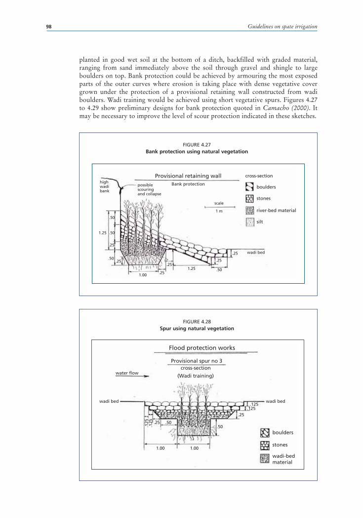
Guidelines on spate irrigation98
FIGURE 4.27Bank protection using natural vegetation
FIGURE 4.28Spur using natural vegetation
planted in good wet soil at the bottom of a ditch, backfilled with graded material, ranging from sand immediately above the soil through gravel and shingle to large boulders on top. Bank protection could be achieved by armouring the most exposed parts of the outer curves where erosion is taking place with dense vegetative cover grown under the protection of a provisional retaining wall constructed from wadi boulders. Wadi training would be achieved using short vegetative spurs. Figures 4.27 to 4.29 show preliminary designs for bank protection quoted in Camacho (2000). It may be necessary to improve the level of scour protection indicated in these sketches.
Provisional retaining wallBank protection
scale
1.25
.50
.50
.50
.25
.25
.251.25
.25.25
.25
.501.00
1 m
possible scouring and collapse
highwadibank
wadi bed
cross-section
boulders
stones
river-bed material
silt
Flood protection works
Provisional spur no 3
.25
.25
.125
.125.125
.125 .50
.50
1.00 1.00
wadi bedwadi bed
water flowcross-section
(Wadi training)
boulders
stones
wadi-bed material

Chapter 4 – Water diversion and control sutructures 99
FIGURE 4.29 Proposed bank protection using retaining wall and spurs with shrubs
Wadi-bank protectionIllustration of the protection on a 500 m wadi-section
using provisional deflectors (3 types), retaining walls and vegetation
70 m
70 m70 m 70 m
70 m
70 m70 m 70 m70 m 70 m
70 m
100 m
100 m
W a d i
3
A mixture of Tamarix aphylla and Saccharum aegypticawould be planted all along the wadi-banks (1 000 m)
provisional deflector type no 1
provisional retaining wall
provisional deflector type no 2
provisional deflector type no 3
sedimentation effect of a deflector
water flow
3
3
2
21
1
1
1
1
222
2
32
3
2

Chapter 5 – Soil and field water management 101
Chapter 5
Soil and field water management
SUMMARYInterventions in spate irrigation have mostly concentrated on improving the diversion of spate flows and much less on improving the productivity of irrigation water. In spite of potentially substantial gains, often little attention is given to soil fertility management, improved field water distribution or better moisture conservation. These components may have as large an impact on crop production as improvement in water supply and should therefore be considered an integral part of spate improvement projects.
Spate soils are largely built up from the heavy sedimentation loads of spate water and thus their textures vary within the spate systems as a result of the sediment transport and depositing pattern. Sediments are important for soil profile development capable of high soil moisture conservation (up to 350 mm/m) and they are also major sources of soil fertility replenishment. However, the high level of sedimentation of spate systems can also represent a problem when field levels rise and go out of command. In designing spate improvement interventions, it is important to consider mitigation measures that farmers apply to cope with their local situations and ensure that proposed interventions will accommodate land rise issues.
Spate soils generally have good water-holding capacities with relatively moderate infiltration rates that vary with soil texture, density and soil management practices. The most common problems with soil are the low organic matter content and the low availability of nitrates and some micro-nutrients. This situation can be improved by incorporating crop residues into the soil, by growing leguminous crops, by practising crop rotation and by growing fodder crops that attract animals and thus providing a larger supply of organic fertilizer through animal dung.
Field water management in spate irrigation systems is as important as effective water diversion. Owing to the great temporal and special variation of its floods, the nature of spate irrigation does not allow farmers to follow a predetermined irrigation schedule where water quantities are applied to a crop when it is needed. This does not mean that water distribution within the command area is either haphazard or unplanned. Water distribution is regulated by prevailing water rights and rules and generally follows a number of principles that includes: a) rapidly spreading the available flows so as to prevent spate water rapidly disappearing in low-lying areas; b) dividing the floods into manageable quantities so as to avoid erosive flows and gully formation; and c) ensuring that large enough water volumes to irrigate the downstream areas are conveyed in the short time that spate flows are available.
One important issue in field water management is the choice between field-to-field irrigation and distribution through canals and individual field outlets. In many spate systems, a rudimentary canal network with field-to-field irrigation is in place. While improved canal networks, supplying water to field outlets, can

Guidelines on spate irrigation102
give better control of water and overcome some of the disadvantages of the field-to-field water system, changing to controlled field outlets may have unforeseen implications. Any improved water distribution system should:
� ensure that irrigation can be carried out quickly, in the short periods that spate flows occur. This requires canal and water control structures that have a much larger discharge capacity in relation to the area served than would be used normally in perennial irrigation systems.
� support the stability and manageability of the distribution network by introducing structures that stabilize the bed of the flood channels and reinforce field-to-field overflow structures and by making sure that gullies are quickly plugged.
� ensure that farmers understand and agree with the implications of any implied changes to water distribution and, where new canals are needed, agree to provide the additional land that will be needed to construct the canals. Additional land that will be needed to construct canals will almost certainly be taken from previously irrigated land.
� ensure that interventions be developed with the farmers, as they are generally the ones most able to identify the opportunities and possibilities for improvement in water distribution.
The design of the command area also plays an important role in field water management. Keeping the command area compact may increase the possibility of making a second irrigation and there are indications that the water productivity of the second irrigation turn is higher than the first. Smaller command areas encourage more investment in pre-irrigation land preparation and bund maintenance, because the predictability of the system is higher and makes it easier to cooperate.
Field bunds play an important role in field water application. There is a relationship between soil water-holding capacity, the likelihood of receiving one or several irrigations, field size and the height of field bunds. Field bunds are typically higher in areas where water supply is less reliable, while they remain relatively low where water supply is frequent and abundant, typically in the upper part of spate schemes. The maintenance of field bunds has a profound impact on water productivity in spate irrigation. Maintaining field bunds is an individual responsibility with a collective impact because, if bunds in one field are neglected, the water will move across the command area in an uncontrolled fashion, not serving large parts of it and causing field erosion at the same time.
A number of techniques are available to improve the control of field water application and distribution. They include better levelling of field bunds so that water overflows over a relatively large stretch, digging a shallow ditch downstream of the bund to spread overflowing water over the entire breadth of the field, the reinforcement of overflow structures, and improved field gates.
Moisture conservation in spate irrigation is at least as important as water supply, especially since in many systems floods arrive well ahead of the sowing season and hence spate irrigation is characterized as ‘pre-planting irrigation’. Several techniques to conserve soil moisture can be applied in spate systems, including ploughing before and after irrigation, conservation tillage, soil mulching, breaking soil crusts and encouraging the burrowing action of insects and crustaceans.

Chapter 5 – Soil and field water management 103
INTRODUCTIONSoil and water management in spate irrigation systems is vital for two reasons. The first is that in spate systems the soils are largely induced by human activity. They are built up from the sediments transported with the spate flows that settle when water is ponded on bunded fields. The water-holding capacity, infiltration and fertility of these soils are usually good, but soil management is required to counter land rise, maintain fertility and in some areas to avoid soil crusting and compaction, as well as to reduce bare soil evaporation and deep percolation losses.
The second reason is the importance of moisture conservation in crop production. In spate systems, irrigation before planting provides the main source of crop moisture. Conserving this moisture is essential to crop production. Good moisture conservation can have an impact on production often greater than improvements to the water diversion systems.
This chapter discusses the development of spate soils and the management of soil quality, water distribution and management at field level and moisture conservation and its techniques.
SOIL MANAGEMENTDevelopment of spate soilsSoils in spate areas are largely built up from sedimentation in the early years of development of a spate system. They are further affected by the continuing sedimentation that is inherent in spate irrigation. A relatively flat stony area can be developed over a few years by irrigating it with sediment-laden spate flows. Farmers in spate schemes often divert water to collect alluvial silt and silt loam sediments to develop soils or provide fertility even when crops do not need water.
The rate that soil builds up varies from one location to another, depending on the sediment yield from catchments, and on the position within a scheme. Sedimentation rates are higher in the upstream fields, as they are irrigated more frequently and are closer to the wadi, while they are relatively lower in downstream areas that rarely receive water. Average siltation rates on spate-irrigated fields in systems in Eritrea, Sudan, Pakistan and Yemen are summarized in Table 5.1.
The constant sedimentation of spate systems is a blessing, as it brings much needed fertility to the fields, but it can turn into a curse when over the longer term it causes field levels to rise above command level. In traditional systems, this can be compensated for over the medium term by moving intakes further upstream and by constructing higher
TABLE 5.1Field rise rates in spate-irrigated areas
Scheme Annual rise rate (cm/year)
Wadi Laba, Eritrea (measured 2003/2004) Upstream fields: 1.0–3.5
Middle fields: 0.8–2.0
Downstream fields: 0.5–1.2
Wadi Laba, Eritrea (long term estimate) 3.0 (IFAD data)
Eastern Sudan 1–3.9
Balochistan mountain systems > 5.0
Wadi Zabid, Yemen Upstream fields: 2–5
Source: Mehari (2007), IFAD (1995), Ratsey (2004), Kahlown & Hamilton (1996)

Guidelines on spate irrigation104
bunds in flood canals to raise water levels. However, in many long-established spate systems one finds areas that are abandoned as they have gone out of command and can no longer be irrigated.
To mitigate land rise, farmers move soil to the field bunds while levelling their fields (see Figure 5.1). In Pakistan, material is scooped from the inner side of the bund, leaving a depression of typically 6–8 m wide on the inner side of a bund. This depression holds the first thrust of water, helps control sedimentation and also prevents in-field gullying by reducing the speed of water entering the field. In Eritrea, it has been reported that the need for large quantities of soil to reconstruct and maintain traditional earthen field bunds and command area structures frequently damaged by floods significantly reduced the number of fields that fell outside the irrigable command area (Mehari, 2007).
Sedimentation within the bunded fields tends to form a series of approximately level terraces (see Figure 5.2), with drops in level between the fields, which help the field-to-field irrigation system to function (Williams, 1979).
Large sediment particles tend to settle out in the canals near the wadi intakes. However sand may be transported to, and be deposited on, fields close to wadi intakes to form coarse sandy soils. Finer sediments, with lower settling velocities, are transported in suspension and can travel with the water to more remote locations. Finer sediments, silts and clays, are mostly transported through the canal systems and are deposited on the fields. As a result soil textures and water retention capacity vary within the spate systems, with soils in the middle part of the wadi normally having the best water retention capacity. For Wadi Abyan in Yemen, water retention capacities for different soil texture classes were compared. Table 5.2 highlights the relatively low water retention capacity of the sandy soils in the upstream areas.
FIGURE 5.1Field bund being strengthened with soil scraped up from irrigated land

Chapter 5 – Soil and field water management 105
In Wadi Laba in Eritrea, the soil profiles are 2.5–3 m deep and are predominantly of silt loam texture. They can retain up to 350 mm/m of water. This implies that the soils could conserve a maximum of 1 050 mm of water within the 3 m deep soil profile and 700 mm within the 2 m deep effective root zone of sorghum and maize (the major spate-irrigated crops) respectively and therefore contribute substantially to satisfying crop water requirements.
Land levellingUnder the field-to-field water distribution system, sedimentation helps in levelling the land and only coarse land levelling is usually carried out by farmers. Farmers often assume that the floodwater will level the land by depositing more sediment in the low spots but this is not always the case (Tesfai, 2001). Too large variations in the levels
FIGURE 5.2Spate-irrigated fields in Wadi Zabid, Yemen
TABLE 5.2Available water in different soils in Abyan delta in Yemen
Soil textural class Available water in 1 m depth of soil (mm)
Loamy sand 39
Sandy loam 83
Silt loam 163
Clay loam 170
Silty clay loam 202
Source: Mu’Allem (1987)
1565500
1565000
1565500
1565000
325000
0.1 0 0.1 0.2 0.3 0.4 0.5 Kilometers
325500
325000 325500

Guidelines on spate irrigation106
within fields lead to over-watering and leaching of plant nutrients at lower levels, and under-watering at higher levels. This results in poor water use efficiency and typically uneven crop growth and yields within the same field (Goldsworthy, 1975; Williams, 1979; Atkins and Partners, 1984; Mu’Allem, 1987). Crops in the low-lying flood-irrigated fields do not grow well and suffer from nitrogen deficiency (Mu’Allem, 1987).
It is common practice for fields to be maintained at a slight slope. In Balochistan (Pakistan), this is done to ensure that rainfall will be collected at one edge of the field,
making cultivation possible in the lowest part of the field in years when there are no significant floods (van Steenbergen, 1997). Individual fields may also retain a slight slope to enable water to flow easily from one field to the other (Makin, 1977).
The difference between the levels and structure of irrigated and non-irrigated soil areas is very clear. Figure 5.3 shows the western boundary of the irrigated area, with relatively deep alluvial soils, and the contrasting lower, sandy, desert scrub land at the western edge of the irrigated area in Wadi Zabid in Yemen.
Soil fertility management in spate systemsSoils in spate systems have generally good water-holding capacities: loams, silty loams, sandy loams and sandy clays are common. In some areas, such as the Wadi Abyan in Yemen, wind erosion has had a negative impact on soils as it has caused fine particles on well-established loamy areas to be blown away. This problem is more severe in areas that are only cultivated infrequently, in particular the tails of the spate systems.
Infiltration rates in irrigated soils vary with soil texture, density and soil management practices (Williams, 1979). Infiltration rates range from 7.5 to 20 mm/hour in highland systems in Balochistan (Kahlown and Hamilton, 1996), from 15 to 23 mm/hour in Wadi Laba and Mai Ule systems in Eritrea (Mehari, 2007), and from 40 to 60 mm/hour in Wadi Rima in Yemen (Makin, 1977a). They are reported as moderately rapid to rapid in Wadi Bana and the Abyan Delta in Yemen (Atkins, 1984).
In many spate areas, soil fertility is not generally an issue. Fertility is ensured by the regular replenishment of fine silts, carrying organic material eroded from the catchments. Farmers in spate systems are often able to correlate the sediment contents of the flood with the part of the catchment where the flood originates. In some exceptional cases farmers even apply a policy of closing the system for spate flows that are known to carry large quantities of salt. Farmers’ perception of regular replacement of fertilizing silts should, thus, always be considered when improvement in spate systems are introduced; otherwise, misunderstanding and conflict may arise between farmers and the engineers responsible for improving the system. An example is given in Box 5.1 for Wadi Laba in Eritrea.
FIGURE 5.3 Boundary between irrigated and non-irrigated
land, Wadi Zabid, Yemen
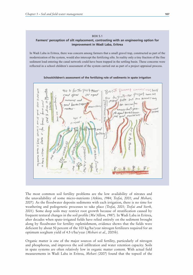
Chapter 5 – Soil and field water management 107
The most common soil fertility problems are the low availability of nitrates and the unavailability of some micro-nutrients (Atkins, 1984; Tesfai, 2001; and Mehari, 2007). As the floodwater deposits sediments with each irrigation, there is no time for weathering and pedogenetic processes to take place (Tesfai, 2001; Tesfai and Sterk, 2001). Some deep soils may restrict root growth because of stratification caused by frequent textural changes in the soil profile (Mu’Allem, 1987). In Wadi Laba in Eritrea, after decades when spate-irrigated fields have relied entirely on the sediment brought along by floodwater for fertility replenishment, evidence shows that the fields were deficient by about 50 percent of the 103 kg/ha/year nitrogen fertilizers required for an optimum sorghum yield of 4.5 t/ha/year (Mehari et al., 2005b).
Organic matter is one of the major sources of soil fertility, particularly of nitrogen and phosphorus, and improves the soil infiltration and water retention capacity. Soils in spate systems are often relatively low in organic matter content. With actual field measurements in Wadi Laba in Eritrea, Mehari (2007) found that the topsoil of the
BOX 5.1
Farmers’ perception of silt replacement, contrasting with an engineering option for improvement in Wadi Laba, Eritrea
In Wadi Laba in Eritrea, there was concern among farmers that a small gravel trap, constructed as part of the modernization of the system, would also intercept the fertilizing silts. In reality only a tiny fraction of the fine sediment load entering the canal network could have been trapped in the settling basin. These concerns were reflected in a school children’s assessment of the system carried out as part of a project appraisal process.
Schoolchildren’s assessment of the fertilizing role of sediments in spate irrigation

Guidelines on spate irrigation108
upstream, midstream and downstream fields have on average 2.5, 1.7 and 0.9 percent of organic matter respectively. The corresponding subsoil samples have slightly lower contents at 1.8, 1.5 and 0.6 percent. The lowest and highest percentages of organic matter in soils are 1 and 5 (Randall and Sharon, 2005). Hence, the upstream fields had (in 2006) slightly below average, and the midstream and downstream fields had low and very low percentages of organic matter respectively. Owing to the field-to-field water distribution practice, the upstream fields might have received more flood water in the past years, which might have given them the edge in the build up of organic matter. Content of less than 1 percent organic matter was also reported in Wadi Rima and elsewhere in Yemen (Girgirah et al., 1987). The low organic matter content of the soils is often related to the sparse natural vegetation in the catchments. The small amount of organic material available decomposes rapidly in the high temperatures that prevail in many areas.
Soil organic matter and fertility can be improved by incorporating crop residues into the soil (but crop residues are often used as fodder), by growing leguminous crops and by practising crop rotation. The practice of planting fodder trees has been promoted in the flood water spreading systems in Iran (Kowsar, 2005). Trees such as Atriplex lentiformis, Acacia salicina, Acacia cyanophylla and Acacia victoriae attracted a population of sheep and cattle, providing a larger supply of organic fertilizer through animal manure. This, in turn, has attracted the dung beetle, whose burrowing action has loosened the soil and increased the infiltration rates of flood water. The introduction of the sowbug (Hemilepistus shirazi Schuttz) has had the same beneficial effect.
FIELD WATER MANAGEMENTInterventions in spate irrigation usually concentrate on improving the diversion of spate flows. Water management within the command area has often been treated as a ‘black box’. In spite of substantial potential gains, there has been little attention to field water application and improved water distribution at field level. Yet, field water management in spate irrigation systems is as important as effective water diversion.
Field water distribution methodsBecause of the special and temporal variations of its floods, farmers are unable to follow a particular irrigation schedule for spate irrigation; they cannot apply water to a crop as needed. In spite of this, water distribution within the command area is neither haphazard nor unplanned. Water distribution is regulated by water rights and rules in force at the time and follows the following principles:
� spate water flows must be spread quickly to prevent its disappearance in low lying areas;
� flood quantities must be divided manageably to prevent erosive flows and the formation of gullies; and
� large enough water volumes should be ensured for downstream irrigation in the brief time spate flows are available.
Beyond these general principles, water distribution within the command area is determined by:
� the prevailing local custom, sometimes derived from Islamic water law (upstream users have priority);
� whether water is distributed field-to-field, or each field has its own inlet from a canal; and
� whether the flood flows are concentrated in a small area or spread over an extensive area.

Chapter 5 – Soil and field water management 109
There are four methods which are commonly known for distributing water at field level in spate irrigation. These methods are grouped into two practices:
� practices in command area water distribution: field-to-field distribution or individual field distribution;
� sizing of command area: extensive distribution or intensive distribution.
Field-to-field water distribution or individual field offtakesIn field-to-field irrigation, there are no tertiary canals and in most cases no secondary canal. In general, all the flow in a canal is diverted to a group of bunded fields by an earthen bund that blocks the canal. When the upstream field of the group commanded by the canal bund is irrigated, water is released by making a cut in the downstream field bund to release water to the next field. This process is repeated until all the fields in command have been irrigated. If the spate continues after all fields have been irrigated, the canal bund is then broken and the process is repeated at a bund constructed further down the canal, at the next diversion point (see Figure 5.4, see also Box 5.2 for field-to-field water distribution in Eritrea).
The alternative to field-to-field water distribution system is to supply fields from individual field inlets on secondary canals. In Yemen and in the eastern lowlands in Eritrea, field-to-field systems are common, whereas in Pakistan individual field intakes are the norm (see Figure 5.5). The dividing line is not absolute and both systems can exist in the same spate irrigation scheme.
In spate irrigation projects, individual field inlets are often preferred to field-to-field inlets because they offer higher control of water distribution. This view, however, needs
FIGURE 5.4Field-to-field water distribution

Guidelines on spate irrigation110
BOX 5.2
Field-to-field water distribution system in Eritrea
In field-to-field irrigation systems in Eritrea, the main canal, musgha-kebir, delivers water to the secondary canal, musgha-sekir. This in turn conveys the water to a block of 20–30 fields, which have one common inlet, locally known as the bajur. The water first enters the most upstream field and, when it is completely flooded, usually to a level of 50 cm, water is conveyed to the immediate downstream field by breaching one of the bunds. This process continues until water stops flowing. Sometimes, when there are no farmers around, the water overtops the bunds to make its way to the next field, but this in most cases severely erodes the field bunds. (Mehari et al., 2005c)
The fields are locally named as siham/kitea and have a roughly rectangular shape and a size of 1–2 ha. They are surrounded by earthen bunds. The height and width of the bunds range from 0.3 m to 1 m, and from 1 to 4 m respectively. The bunds that border only a single field are called kifafs (singular: kifaf) and the bunds that enclose two or more fields are called tewalis (singular: tewali).
Sketch of field-to-field water distribution system in Eritrea
Severly eroded field bund in Wadi Laba, Eritrea (Mehari et al., 2005b)
wadi
Mushga
Siham/Kitea
To the next field
Mushga sekiragim
Bajur
Kifaf
Tewali
Mushga Kebir
May be used indownstream or is lostto the Red Sea
to downstream fields

Chapter 5 – Soil and field water management 111
to be qualified. Field-to-field irrigation is well adapted to spate irrigation: it allows large volumes of water to be applied to fields rapidly in the short time periods that spate floods flow, helps to control sediments and level the land, is well established and based on existing water rights and management rules and requires minor initial investment.
On the other hand, well designed individual field distribution systems can provide substantial improvement in field water distribution and therefore increase overall water productivity. They help to reduce scours in field offtakes, increase the flexibility of water distribution, allow for irrigation of downstream fields without damaging upstream fields and require less maintenance. However, they need to be adapted to the specific conditions of spate irrigation. Conventional water distribution systems based on perennial irrigation practice, with many small field outlets open at the same time, cannot achieve the same results in spate systems, where water has to be supplied at high flow rates to large areas.
Some controlled systems use secondary canals to supply very large plots at high flow rates. However, large fields can introduce new inefficiencies. In their study on field water application efficiency in large (5 ha) fields in Balochistan, Kahlown and Hamilton (1996) estimated that 1 m of water would need to be applied to achieve 200 mm moisture storage, while the rest went into deep percolation. Internal bunds dividing the fields into smaller areas (0.5–1 ha) could help improve distribution uniformity.
The relative advantages and disadvantages of field-to-field and individual controlled systems are compared in Table 5.3. The choice of the water distribution system to be adopted will depend on local conditions and needs to be negotiated with the farmers. Table 5.3 can be used to assess the positive and negative aspects of both systems and their relative importance in a given context. If water distribution rules are well established, and farmers do not consider that the existing field-to-field system represents a major constraint, such a system can be maintained, possibly with some improvements to field offtakes, as described in a later section in this chapter. Instead, if farmers identify major shortcomings in the existing system, options for improvement, and implications in terms of operation, maintenance and distribution rules may be analysed and used as a basis for the design of an improved field water management system. The design of the system itself, including the layout of the canals, the selection of groups of farmers to be served by a canal, as well as the possible need for land redistribution need to be carefully negotiated between the farmers and the engineers in charge of the spate improvement works.
There is a third, more rudimentary way of field water distribution which involves the use of guide bunds that spread floodwater over a large area. Spate systems with guide bunds are found in the western lowlands in Eritrea where most of the spate irrigation is very recent, much of the irrigation is on land that was rainfed earlier, where soils are already well developed, though not deep enough to ensure a pre-planting system. Guide
FIGURE 5.5Individual field distribution system in Pakistan

Guidelines on spate irrigation112
bunds are also used in the still very rudimentary Tokar system in Sudan. The guide bund system does not favour soil development and, as fields are not bunded, they do not allow the water to be impounded and infiltrate slowly. This approach often does not lead to sufficient retention of residual soil moisture. It is therefore not recommended when spate flow is the major source of irrigation but could be applied at a lower cost in situations where spate flow is used as a supplementary water supply.
TABLE 5.3Comparison between field-to-field and individual water offtakes
Field-to-field irrigation systems Individual water offtakes
No land is required for secondary canals. Land required for secondary and tertiary canals is estimated to be within the range of 10–25 percent of total area, though at the end of season canal beds are sometimes cultivated (Mehari, 2007).
Water distribution usually well regulated by local rules, although timing of breaching can be a source of conflict.
Gated control structures make it possible to divert water at any time and in contravention of established water rights.
Gated control structures imply new water distribution practices which may differ substantially from established water rights.
Compulsory maintenance of system often regulated by local rules.
Farmers need to adapt to new operation and maintenance rules.
The breaching of the field bunds helps to remove large quantities of sediment from the command area and reduce the risk of rising command areas getting out of command.
Less scope to remove sediments from the command areas naturally – as signified by very high field bunds. In flat areas this can be a significant problem.
Help to level land in irrigation fields. When plots are large, the lack of levelling will create uneven irrigation.
No problem of canal sedimentation. Sedimentation in canals affects their ability to provide water to the downstream fields.
Damage of upstream field bunds may jeopardize flows to lower areas.
Group water supply is not vulnerable to breaking of individual field bunds.
Smaller floods do not reach tail-end plots. Individual offtakes allow for more flexibility and the possibility of irrigating downstream fields even later in the season without damage to upstream crops
Smaller floods later in season are not diverted because upstream plots are cultivated.
Possible damage to growing crops during second or third irrigations.
Minor investment but high, labour- intensive maintenance costs.
Require expensive investment in gated flow control and division structures and field offtakes with a high flow capacity.
In-field scour on lands result from the breaching of downstream bund.
Gated structures reduce risk of scour and improve water application regulation.
Abrupt changes in elevation from field to field, with scour problems and impossibility of regulating the depth of water application correctly.

Chapter 5 – Soil and field water management 113
Extensive or intensive water distributionAnother factor distinguishing methods of water distribution at field level is whether irrigation is spread widely or concentrated in a small area. Whereas in extensive systems a single irrigation is common, fields may be irrigated twice or three times before cultivation when floods are concentrated on a small area. Local crop varieties are well adjusted to soil moisture stress, but even so, there is evidence that for the sorghum crop in Yemen (Makin, 1977 and Williams, 1979) and sorghum and maize crops in Eritrea (Mehari, 2007), the yield produced from two or three irrigations would be more than two or three times the yield from a larger area irrigated once.
Both types of water distribution pattern can exist in the same system and depend in part on the moisture-holding capacity of the soil. Makin (1977) describes the use of base flows and small floods to provide several irrigations near the mountain front in Wadi Rima in Yemen and the contrasting pattern of a single large irrigation at the tail of the same system. In some other cases, farmers avoid irrigating their land for a second time, particularly if a crop is established on the land. In Las Bela District in Balochistan (Pakistan), sorghum may be irrigated twice, but if it is mixed with pulses or sesame, farmers say that crops are damaged by a second flooding and more subject to disease. Once the crops come up, farmers are hesitant to put floodwater on the land, as it would damage the young plants. Similarly, later in the season when the crop stands are higher, there is the fear that additional irrigation would invite pests and floods that come late in the season may be diverted to other areas.
The design of the command area therefore plays an important role in field water management. Keeping the command area compact may increase the possibility of making a second irrigation, and there are indications that the water productivity of the second irrigation turn is higher than the first. Smaller command areas also encourage more investment in pre-irrigation land preparation and bund maintenance, because the predictability of the system is higher and makes it easier to co-operate.
The choice of an intensive or extensive system is related more to the flood pattern and to the agreed water rights than to considerations of crop response to water. Concentrating spate supplies on a small area will make it easier to decide where to plough prior to the spate season with the aim of improving infiltration rates on those fields where irrigation is possible. However, some systems are not amenable to intensification. The spate systems in the Suleiman plains and Kacchi plains in Pakistan depend on a single soil bund that is supposed to be broken when the irrigation is over. As long as the bund stands, land can be irrigated, but after it is breached there may not be a second chance. Moreover, some of the smaller rivers may carry only one substantial flood in a year.
Improvements can be introduced through tests and demonstrations of different options for intensification of water application and subsequent results in terms of crop yield for different crops. Care must be taken, in this case, of considering the inter-annual variability of supply and assessing the implication of possible changes in the water distribution pattern for water rights.
Field water application and the importance of field bundsIn spate irrigation, it is generally assumed that irrigation application should result in an average of 400 mm net stored in the soil (Camacho, 1987). It is also reported that the application of 600–1 000 mm of water in a single pre-planting irrigation is sufficient to raise all spate-irrigated crops, provided that the moisture-holding capacity of the soil is satisfactory (Mu’Allem, 1987). In the spate systems in Sudan, 500 mm is used as the norm, with a single watering per season. In other areas, the preference is for several

Guidelines on spate irrigation114
irrigations. In Eritrea, arable fields are flooded three to four times, with an irrigation gift of about 50 cm each time, giving a wetting depth of about 2–2.4 m in the soil profile.
There is a relationship between the height of field bunds and the availability of water both in terms of frequency and volume of irrigation. In Wadi Rima in Yemen, in locations where crops can expect to receive only a single irrigation, the bunds are high and the depth of the water application averages 400 mm. In locations closer to the wadi, which can expect two or more irrigations per crop, bunds are lower and the amount of water absorbed for each irrigation averages 300 mm (Makin, 1977). In Yanda-Faro in South Ethiopia, field bunds are 20 cm high, not different from field bunds in perennial systems. In Daraban Zam in Pakistan, they can be up to 3 m. In systems with large plots, bund heights may easily reach 2–3 m. The depth of water that can be impounded in a bunded field during particular irrigations often affects the choice of crop grown. Box 5.3 illustrates different scenarios for water impounded in bunded fields in Balochistan (Pakistan), Yemen and Eritrea.
The maintenance of field bunds has a profound impact on water productivity in spate irrigation. Maintaining field bunds is an individual responsibility with a collective impact, because, if bunds in one field are neglected, the water will move across the command area in an uncontrolled fashion, not serving large parts of it and causing field erosion at the same time. The importance of maintenance can be derived from its central place in some of the management arrangements in spate systems. In the rules and regulations for spate systems in Wadi Laba in Eritrea and Wadi Tuban in Yemen, there were explicit penalties for farmers who did not take sufficient care in maintaining the field bunds, that could go as far as compensating for the crop loss of the disadvantaged neighbour. A step further is the hereditary tenancy arrangements that are common in
BOX 5.3
Different scenarios for water impounded in fields and choice of crops grown in Pakistan, Yemen and Eritrea
� In Las Bela District in Balochistan, if 300 mm are impounded, then guar (cluster bean) alone is sown, mainly as a fodder; if 750 to 900 mm are stored, then castor is sown; otherwise a mix of sorghum, mung and sesamum/guar is sown. Farmers generally do not aim to achieve depths of over 900 mm. Mustard is only planted when two or more floods can be impounded on the same plot prior to cultivation.
� In Kacchi District in Balochistan, when there is little floodwater, the land is inspected after the water has receded. If the depth of wetting is insufficient, crops are only sown in depressions or adjacent to unbreached bunds.
� In Nal Dat in Balochistan and where the depths of water applied are insufficient to meet the crop water requirements for all crops, rainfall is relied upon for meeting the deficit.
� In parts of Bateis command in Wadi Bana in Yemen, farmers apply more than 750 mm of water to cotton, 250 mm more than is required by the crop. Not all this water may be absorbed by the soil – the balance recharges the aquifers.
� In Eritrea, if the farmers irrigate their fields three times (1 500 mm), they plant maize as a second crop. When the total irrigation supply is less than 1 000 mm, the more drought-resistant sorghum ratoon of the hijeri local variety is preferred.
Sources: MacDonald (1987a), Halcrow (1993b), and Mehari (2007).
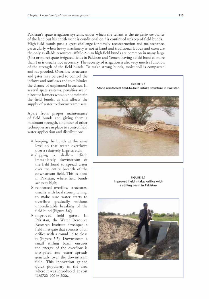
Chapter 5 – Soil and field water management 115
Pakistan’s spate irrigation systems, under which the tenant is the de facto co-owner of the land but his entitlement is conditional on his continued upkeep of field bunds.High field bunds pose a great challenge for timely reconstruction and maintenance, particularly when heavy machinery is not at hand and traditional labour and oxen are the only available resources. While 2–3 m high field bunds are common in many large (5 ha or more) spate-irrigated fields in Pakistan and Yemen, having a field bund of more than 1 m is usually not necessary. The security of irrigation is also very much a function of the strength of the field bunds. To make strong bunds, moist soil is compacted and rat-proofed. Overflow structures and gates may be used to control the inflows and outflows and to minimize the chance of unplanned breaches. In several spate systems, penalties are in place for farmers who do not maintain the field bunds, as this affects the supply of water to downstream users.
Apart from proper maintenance of field bunds and giving them a minimum strength, a number of other techniques are in place to control field water application and distribution:
� keeping the bunds at the same level so that water overflows over a relatively large stretch;
� digging a shallow ditch immediately downstream of the field bund to spread water over the entire breadth of the downstream field. This is done in Pakistan, where field bunds are very high;
� reinforced overflow structures, usually with local stone pitching, to make sure water starts to overflow gradually without unpredictable breaking of the field bund (Figure 5.6);
� improved field gates. In Pakistan, the Water Resource Research Institute developed a field inlet gate that consists of an orifice with a round lid to close it (Figure 5.7). Downstream a small stilling basin ensures the energy of the overflow is dissipated and water spreads generally over the downstream field. This innovation gained quick popularity in the area where it was introduced. It cost US$700–900 in 2006.
FIGURE 5.6Stone reinforced field-to-field intake structure in Pakistan
FIGURE 5.7Improved field intake, orifice with
a stilling basin in Pakistan

Guidelines on spate irrigation116
MOISTURE CONSERVATIONMoisture conservation in spate irrigation is as important as water supply, as crop yields can be severely depressed by soil moisture deficit. Farmers in the coastal eastern lowlands in Eritrea, for example, estimate that a person who has his own bullocks would have a yield 30–100 percent higher than another who does not own bullocks. The reason for this difference is that, with draught animals of one’s own, one could plough fields and repair bunds after every irrigation, thus vastly increasing soil moisture retention. Research in Yemen suggests that, if land is not ploughed within two weeks after irrigation, up to 30–40 percent of the moisture may be lost. Several techniques to conserve soil moisture are applied in spate systems:
� ploughing prior to and after irrigation; � conservation tillage and soil mulching; � breaking soil crusts.
Ploughing prior to and after irrigationBreaking the topsoil through ploughing land prior to irrigation greatly increases infiltration rates (see Figure 5.8). Makin (1977) reported that initial infiltration rates for Wadi Rima in Yemen increased from 40 to 60 mm/hour. Pre-irrigation ploughing also makes cultivation much easier and quicker to carry out once the floodwaters arrive, which is important, as a great deal of labour is required to cultivate the land after irrigation (Williams, 1979).
There is a close link between the practice of pre-ploughing irrigation and the likelihood of water supplies. In areas where the probability of irrigation is low, for example in intensive systems, it is unlikely that farmers will invest time and effort in soil preparation.
FIGURE 5.8Ploughing prior to irrigation to break topsoil

Chapter 5 – Soil and field water management 117
The topsoil should be ploughed loosely after irrigation or rainfall (see Figure 5.9) to conserve water (Williams, 1979). However, as the soil is wet, it may not be possible to plough the land for 8–12 days after irrigation, and some water will inevitably evaporate (Makin, 1977). The common recommendation is not to delay ploughing for more than two to three weeks, to avoid water loss through evaporation or deep percolation. Extending the post-irrigation period beyond that time may cause a moisture loss in the range of 40 percent. In the Kacchi District in Balochistan, where soils are relatively clayey, fields tend to dry out at the surface. It then becomes important to drill seed deep into the soil. Farmers can only plough fields once and the seedbed is often too cloddy for good, even germination and establishment (MacDonald, 1987a).
Smallscale farmers in coastal south Yemen reportedly ‘bury the irrigation’ when the floods come out of season. They plough the land and ensure the topsoil is loose. In some instances they even cover the land with sorghum stalks to reduce evaporation losses further.
In Eritrea, combining ploughing and sowing minimizes the degree of compaction of the subsoil and thereby enhances the soil’s hydraulic conductivity and infiltration rate. Farmers use the jeleb, which is a hollow plastic tube into which the plough operator drops two or more seeds every few seconds while tilling the land (see Figure 5.10). The reduction of the degree of compaction through simultaneous ploughing and sowing is considered to be the main reason behind the low soil bulk density of the Wadi Laba fields, which has been maintained at about 1–1.3 kg/m3. A bulk density of 1 600 kg/m3 affects root growth, one of 1 800 kg/m3 severely restricts it (Mehari, 2007).
Conservation tillage and soil mulchingConservation tillage in Sheeb in Eritrea is called mekemet, a term derived from the local Tigre word kememnaha, which literally means: “we have sealed it”. This technique is practised in the approximately ten-day period between the last flooding
FIGURE 5.9Ploughing after irrigation/rainfall for moisture conservation, Sheeb, Eritrea
FIGURE 5.10Simultaneous ploughing and sowing using the jeleb in Wadi Laba, Eritrea

Guidelines on spate irrigation118
and the sowing of seeds. It can also be done earlier if the field is not expected to get any additional irrigation. Farmers plough the fields about 0.15 m deep to create a tilth,
which conserves the soil moisture by reducing the evaporation losses from the soil surface. At sowing time, the tilth layer is broken down by shallow tillage followed by sowing (Tesfai, 2001). Soil moisture measurement in twelve selected Wadi Laba fields has shown that mekemet can conserve as much as 20 percent of the soil moisture that would have otherwise been lost to evaporation (Mehari, 2007). During operation, the farmer (operator) stands on the oxen-drawn wooden plate and scoops up a thin layer of soil, mulching surface soil pores (see Figure 5.11). The same practice is reported from Ethiopia, Pakistan and Yemen, where farmers try throughout the growing season to keep the topsoil loose to reduce evapotranspiration.
Breaking soil crustsIn areas with silt soils or calcareous soils, soil crusting can affect water use efficiency. Such soils may form surface crusting, which can reduce the infiltration rate by 20–40 percent (Mehari, 2007) and thereby affect the amount of residual soil moisture. Therefore, special measures are required to keep the topsoil loose to avoid frequent field trampling. In the piedmont plains of the Sulaiman Range in Pakistan, clayey soils, including silty clays, clays and silty clay loams, form a major part of the Rod Kohi land (Khan and Rafiq, 1990). They are generally more difficult to till and are prone to surface cracking. The soil crust that develops reduces the infiltration rate, increases runoff, restricts seedling emergence and reduces crop yield (Nizami and Akhtar, 1990). Appropriate management and agronomic techniques include tillage, surface mulching, increase in soil organic material (by applying manure and incorporating crop residues where possible), seeding at appropriate (15–20 cm) depth, planting on ridges and use of mechanical crust breakers (Nizami and Akhtar 1990; Tesfai, 2001).
Silt soils are prone to compaction if machines are used on wet soils. Soil compaction slows down root penetration. Soil water and nutrients become less accessible to the plant and crops grown on compacted soils will show the effects of drought stress first. Continuous flood irrigation may lead to a hard compact layer at a depth of 30–40 cm. Clay particles carried in the floodwater are washed down the profile and make it difficult for the plant roots to reach the water, which leads to a reduction in productivity. One option to address this problem would be to break the hard pan every two to three years by chiselling, using a heavy power unit.
FIGURE 5.11Soil mulching, mekemet in Wadi Laba, Eritrea