chapter 30 the law of reflection
TRANSCRIPT
Chapter 30 The Law of Reflection“It follows that each little region of a luminous body,such as the Sun, a candle, or a burning coal, generatesits own waves of which that region is the center. Thusin the flame of a candle, having distinguished thepoints A, B, C, concentric circles described about eachof these points represent the waves which come fromthem. And one must imagine the same about everypoint of the surface and of the part within the flame.” Christian Huygens
30.1 Light as an Electromagnetic WaveIn chapter 29 we saw that light is an electromagnetic wave; a transverse wave thattravels through empty space at the speed of 3.00 × 10⁸ m/s or 186,000 miles/s. Therelation between the wavelength λ, frequency ν, and speed c of the light is given bythe fundamental equation of wave propagation as
λν = c (30.1)
Notice that we are now using the Greek lower case letter ν (nu) to representfrequency rather than the letter f, we used previously in the study of wave motion.This usage is customary in physics, especially when dealing with electromagneticradiation in modern physics.
The wavelength of visible light varies from about 3.8 × 10⁻⁷ m for violet lightto the longer wavelength of red light at 7.2 × 10⁻⁷ m. Since the wavelength of lightis so small, we commonly use the nanometer1 (nm), where
1 nm = 10−9 m
In these units visible light varies from about 380.0 nm to about 720.0 nm. A great deal of research went into optics, the study of light, before its
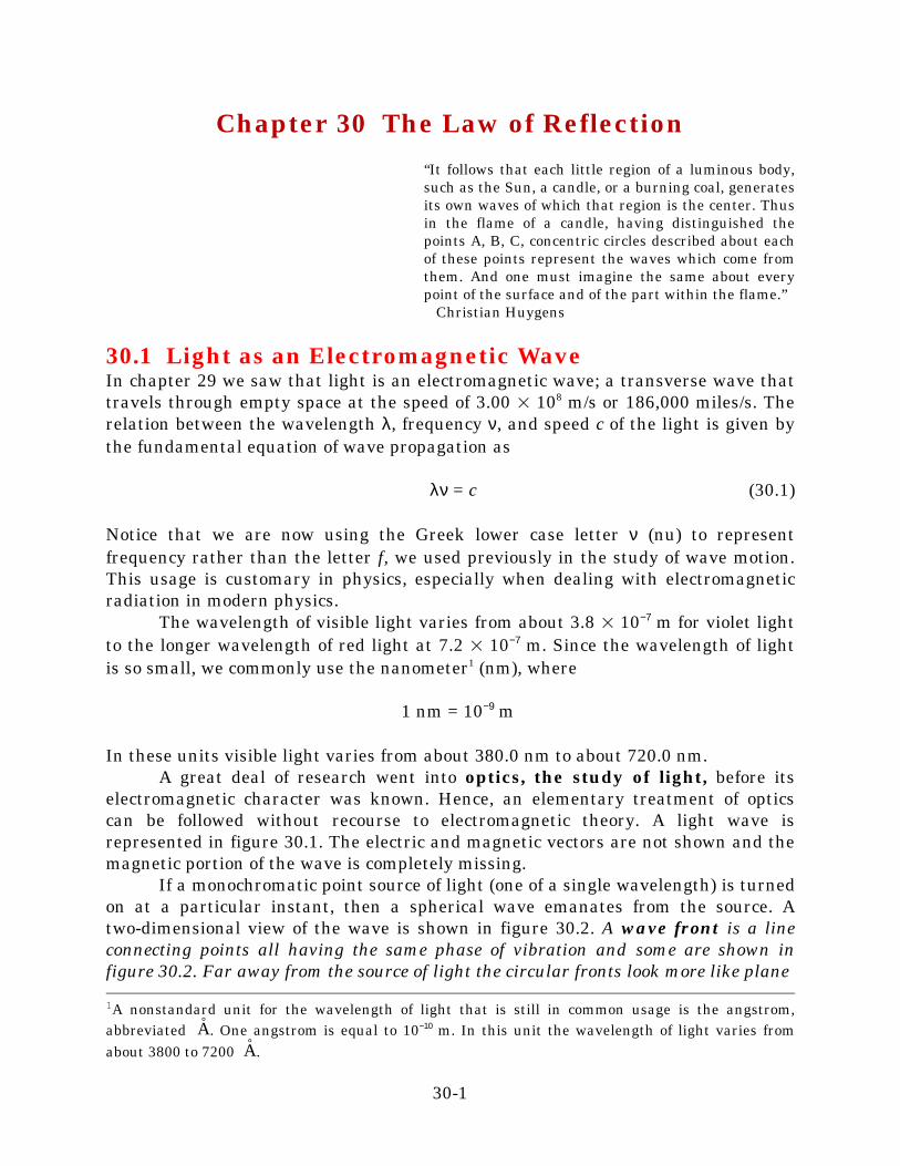
electromagnetic character was known. Hence, an elementary treatment of opticscan be followed without recourse to electromagnetic theory. A light wave isrepresented in figure 30.1. The electric and magnetic vectors are not shown and themagnetic portion of the wave is completely missing.
If a monochromatic point source of light (one of a single wavelength) is turnedon at a particular instant, then a spherical wave emanates from the source. Atwo-dimensional view of the wave is shown in figure 30.2. A wave front is a lineconnecting points all having the same phase of vibration and some are shown infigure 30.2. Far away from the source of light the circular fronts look more like plane
30-1
1A nonstandard unit for the wavelength of light that is still in common usage is the angstrom,abbreviated . One angstrom is equal to 10−10 m. In this unit the wavelength of light varies fromAÿabout 3800 to 7200 .Aÿ
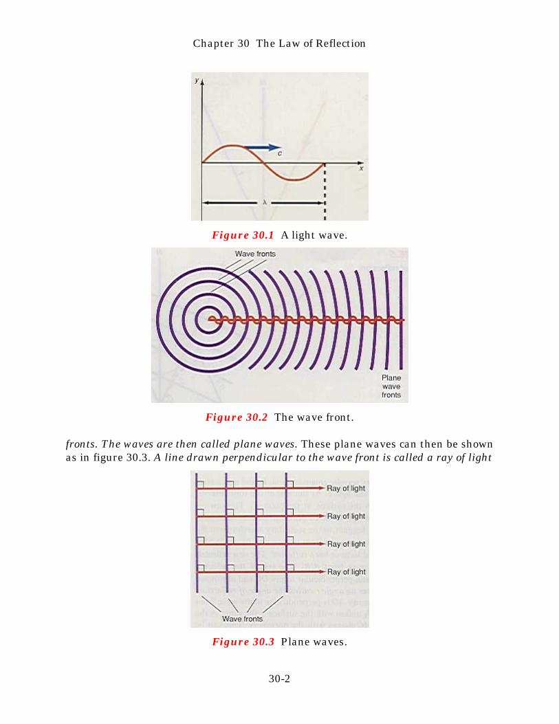
Figure 30.1 A light wave.
Figure 30.2 The wave front.
fronts. The waves are then called plane waves. These plane waves can then be shownas in figure 30.3. A line drawn perpendicular to the wave front is called a ray of light
Figure 30.3 Plane waves.
Chapter 30 The Law of Reflection
30-2
and represents the direction of propagation of the light wave. Note that the ray oflight travels in a straight line. The wavelength of light is so small that in arelatively short distance away from the point source of light, the waves appearplane. Even if the source of light is not a point, when we are sufficiently far awayfrom the source, the waves are effectively plane. In all the subsequent discussionswe will assume that all the light waves are plane waves.
This analysis of light into waves and rays allows us two different descriptionsof light. When only the light rays are dealt with in the analysis of an optical system,the description is called geometrical optics. When the analysis of an optical systemis done in terms of waves, the description is called wave optics or physical optics.Still another description of light is possible by treating light as little bundles ofelectromagnetic energy, called photons. Such a description is called quantum opticsand will be discussed later in chapter 35. Except for the analysis of the laws ofreflection and refraction by wave motion in sections 30.2, 31.1, and 31.2, chapters30 and 31 discuss geometrical optics. Chapter 32 deals with wave optics.
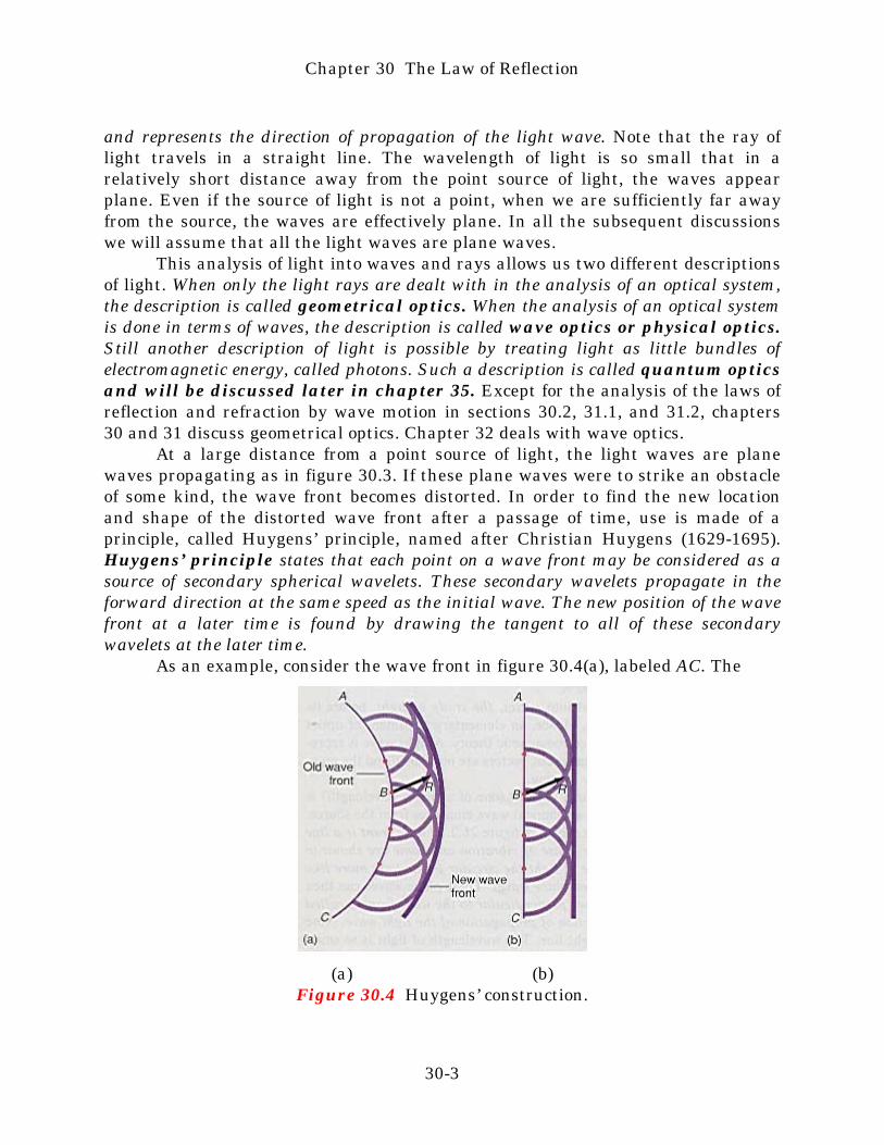
At a large distance from a point source of light, the light waves are planewaves propagating as in figure 30.3. If these plane waves were to strike an obstacleof some kind, the wave front becomes distorted. In order to find the new locationand shape of the distorted wave front after a passage of time, use is made of aprinciple, called Huygens’ principle, named after Christian Huygens (1629-1695).Huygens’ principle states that each point on a wave front may be considered as asource of secondary spherical wavelets. These secondary wavelets propagate in theforward direction at the same speed as the initial wave. The new position of the wavefront at a later time is found by drawing the tangent to all of these secondarywavelets at the later time.
As an example, consider the wave front in figure 30.4(a), labeled AC. The
(a) (b)Figure 30.4 Huygens’ construction.
Chapter 30 The Law of Reflection
30-3
points marked on the wave front, AC, act as a source of secondary waves. Thesecondary wavelets travel a distance R, given by
R = v∆t
where v is the speed of both the initial wave AC and the wavelet and ∆t is the timeinterval considered. The point B in figure 30.4 represents the source of one suchwavelet. The tangent to all these secondary wavelets is shown as the new wavefront in the figure. A similar case is shown in figure 30.4(b) for plane waves. Animportant application of Huygens’ principle is found in the law of reflection.
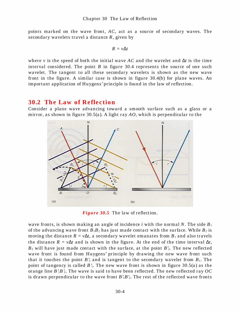
30.2 The Law of ReflectionConsider a plane wave advancing toward a smooth surface such as a glass or amirror, as shown in figure 30.5(a). A light ray AO, which is perpendicular to the
Figure 30.5 The law of reflection.
wave fronts, is shown making an angle of incidence i with the normal N. The side B1
of the advancing wave front B1B2 has just made contact with the surface. While B2 ismoving the distance R = v∆t, a secondary wavelet emanates from B1 and also travelsthe distance R = v∆t and is shown in the figure. At the end of the time interval ∆t,B2 will have just made contact with the surface, at the point B’2. The new reflectedwave front is found from Huygens’ principle by drawing the new wave front suchthat it touches the point B’2 and is tangent to the secondary wavelet from B1. Thepoint of tangency is called B’1. The new wave front is shown in figure 30.5(a) as theorange line B’1B’2. The wave is said to have been reflected. The new reflected ray OCis drawn perpendicular to the wave front B’1B’2. The rest of the reflected wave fronts
Chapter 30 The Law of Reflection
30-4
are drawn parallel to B’1B’2 and perpendicular to ray OC and are shown in thefigure. The reflected ray OC makes an angle r called the angle of reflection, with thenormal N. Because the incident ray AO is perpendicular to the wave front B1B2, theangle that the wave front B1B2 makes with the surface is the same as the angle ofincidence i that incident ray AO makes with the normal N. This can be seen bylooking at triangle B1EO. For the moment, call angle EB1O, the angle θ. The sum ofall the angles in triangle B1EO must equal 1800. That is,
θ + α + 900 = 1800
butα + i = 900
orα = 900 − i
Therefore,θ + (900 − i) + 900 = 1800
andθ = i
as stated. Similarly, since reflected ray OC is perpendicular to reflected wave frontB’1B’2, the reflected wave front B’1B’2 makes an angle r with the reflecting surface.We see in the figure that in triangle B1B2B’2,
sin i = v∆t (30.2) B1B’2
While from triangle B1B’1B’2, we see that
sin r = v∆t (30.3) B1B’2
Since the right-hand side of equation 30.2 is equal to the right-hand side of equation30.3, we have
sin i = sin ror
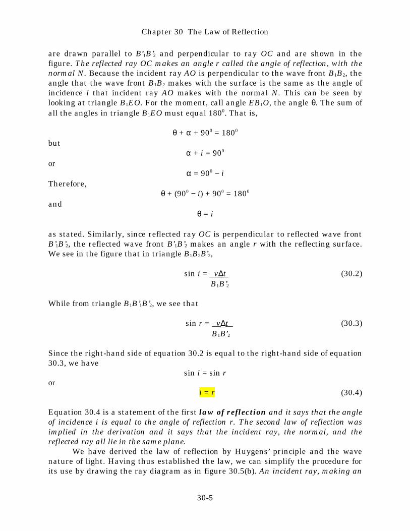
i = r (30.4)
Equation 30.4 is a statement of the first law of reflection and it says that the angleof incidence i is equal to the angle of reflection r. The second law of reflection wasimplied in the derivation and it says that the incident ray, the normal, and thereflected ray all lie in the same plane.
We have derived the law of reflection by Huygens’ principle and the wavenature of light. Having thus established the law, we can simplify the procedure forits use by drawing the ray diagram as in figure 30.5(b). An incident ray, making an
Chapter 30 The Law of Reflection
30-5
angle i with the normal, is reflected such that the reflected ray makes an angle r,which is equal to the angle i. In the rest of this chapter, we will apply the law ofreflection by using ray diagrams only.
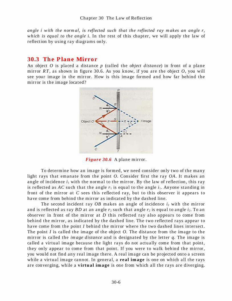
30.3 The Plane MirrorAn object O is placed a distance p (called the object distance) in front of a planemirror RT, as shown in figure 30.6. As you know, if you are the object O, you willsee your image in the mirror. How is this image formed and how far behind themirror is the image located?
Figure 30.6 A plane mirror.
To determine how an image is formed, we need consider only two of the manylight rays that emanate from the point O. Consider first the ray OA. It makes anangle of incidence i1 with the normal to the mirror. By the law of reflection, this rayis reflected as AC such that the angle r1 is equal to the angle i1. Anyone standing infront of the mirror at C sees this reflected ray, but to this observer it appears tohave come from behind the mirror as indicated by the dashed line.
The second incident ray OB makes an angle of incidence i2 with the mirrorand is reflected as ray BD at an angle r2 such that angle r2 is equal to angle i2. To anobserver in front of the mirror at D this reflected ray also appears to come frombehind the mirror, as indicated by the dashed line. The two reflected rays appear tohave come from the point I behind the mirror where the two dashed lines intersect.The point I is called the image of the object O. The distance from the image to themirror is called the image distance and is designated by the letter q. The image iscalled a virtual image because the light rays do not actually come from that point,they only appear to come from that point. If you were to walk behind the mirror,you would not find any real image there. A real image can be projected onto a screenwhile a virtual image cannot. In general, a real image is one on which all the raysare converging, while a virtual image is one from which all the rays are diverging.
Chapter 30 The Law of Reflection
30-6
Thus, rays AC and BD are diverging away from the virtual image I and will nevercross on the left-hand side of the mirror.
We should also note that there is a third ray that can be used. This is the raythat is perpendicular to the mirror. Since its angle of incidence is zero, its reflectedangle is also zero, and the ray is reflected back along the normal. This ray appearsto come from directly behind the mirror and is also indicated by a dashed line thatcomes from the image point I.
In the triangle OSA the angle AOS is also equal to i1 becausealternate-interior angles of two parallel lines are equal. Using similar reasoning,angle AIS of triangle SIA is equal to angle r1. From triangle OSA we have
tan i1 = opposite = SA (30.5) adjacent pwhile from triangle SIA
tan r1 = SA (30.6) q
But the law of reflection states that the angle r1 is equal to the angle i1. Equating30.5 to 30.6 leads to
q = p (30.7)
Equation 30.7 says that the image is as far behind the mirror as the object is in frontof it.
In general, to describe an optical image three words are necessary: its nature(real or virtual), its orientation (erect, inverted, perverted), and its size (enlarged,true, or reduced). Recall that when you look into a mirror your image is reversed.That is, if you hold up your right hand in front of the mirror, your image appears asthough the left hand was held up. This inversion of left-right symmetry is calledperversion. Thus, a plane mirror produces a virtual, perverted, true image.
Example 30.1
An image in a plane mirror. If an object 15.0 cm high is placed 20.0 cm in front of aplane mirror, where is the image located and how high is the image?
Solution
The example is illustrated in figure 30.7. A ray from the top and bottom of theobject is drawn normal to the mirror. These rays are reflected upon themselves, asshown. The top and bottom of the object appear to come from the dashed linesbehind the mirror. Another ray OB is reflected from the mirror as ray BC. If thisray is produced backward it intersects the dashed line from the top of the object at I,producing the image.
Chapter 30 The Law of Reflection
30-7

Figure 30.7 Finding the height of an image for a plane mirror.
From the triangles we havetan i = ho (30.8) p
where ho is the height of the object and p is the object distance. Also from the figure,
tan r = hi (30.9) q
where hi is the height of the image and q is the image distance. The image distancefor the plane mirror, found from equation 30.7, is
q = p = 20.0 cm
And since i = r, by the law of reflection, equation 30.9 is equal to equation 30.8, andhence
hi = ho (30.10)
Equation 30.10 says that for a plane mirror, the height of the image hi is equal to theheight of the object ho. For this example, ho = 15.0 cm, therefore, hi is also equal to15.0 cm. When the height of the image is the same height as the object, the image issaid to be true.
Example 30.2
Minimum size of a mirror. What is the minimum height of a plane mirror such thata woman of height ho can see herself full length?
Chapter 30 The Law of Reflection
30-8
Solution
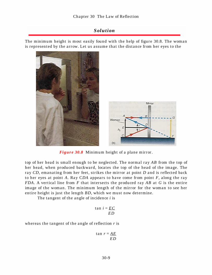
The minimum height is most easily found with the help of figure 30.8. The womanis represented by the arrow. Let us assume that the distance from her eyes to the
Figure 30.8 Minimum height of a plane mirror.
top of her head is small enough to be neglected. The normal ray AB from the top ofher head, when produced backward, locates the top of the head of the image. Theray CD, emanating from her feet, strikes the mirror at point D and is reflected backto her eyes at point A. Ray CDA appears to have come from point F, along the rayFDA. A vertical line from F that intersects the produced ray AB at G is the entireimage of the woman. The minimum length of the mirror for the woman to see herentire height is just the length BD, which we must now determine.
The tangent of the angle of incidence i is
tan i = EC ED
whereas the tangent of the angle of reflection r is
tan r = AE ED
Chapter 30 The Law of Reflection
30-9
Because the angle i is equal to the angle r by the law of reflection, these twotangents are equal, and hence,
EC = AE ED EDor
EC = AE (30.11)But, as we can see from the figure
AE + EC = ho
the height of the object. Using equation 30.11, this becomes
AE + AE = ho
2AE = ho
AE = ho
2
But, as we can see from the figure, AE = BD, the length of the mirror. Therefore, theminimum height of the mirror is
BD = ho 2
That is, the woman needs a mirror that is at least half her size, in order to see theentire length of her body in the mirror.
Determining the image of an object with a plane mirror is, as we have seen,rather simple. But what if the reflecting surface is not a plane? How do we find theimage then? We will now consider a spherical reflecting surface and find the imageof an object for that spherical surface. But remember there are many otherreflecting surfaces that could be considered such as parabolas, cylinders, and so on.
30.4 The Concave Spherical MirrorA spherical mirror is a reflecting surface, whose radius of curvature is the radiusof the sphere from which the mirror is formed, figure 30.9. Here C is the center ofcurvature of the mirror and R is its radius of curvature. The line going through thecenter of the mirror, the vertex in figure 30.10, is called the principal axis, or opticalaxis, of the mirror. Light rays that are parallel and close to the principal axis of theconcave mirror converge to a point called the principal focus F of the mirror. Weshould note here that if a light source were placed at the principal focus, light raysfrom the principal focus would retrace the same path, coming out parallel to theprincipal axis after reflection. This is a principle of optics sometimes referred to as
Chapter 30 The Law of Reflection
30-10

Figure 30.9 A concave spherical mirror.
Figure 30.10 Parallel light converges to the principal focus of a concavespherical mirror.
the principle of reversibility. It can be stated formally as: if a ray traces a certainpath through an optical system in one direction, then a ray sent backward throughthe system along the same path, traverses the original path and comes out along theline that the original ray entered. Let us now determine the location of the principalfocus of a concave spherical mirror.
Focal Length of a Concave Spherical MirrorConsider a single ray AB parallel to the principal axis, as shown in figure 30.11. Thenormal N to the reflecting surface at point B is actually an extension of the radius ofcurvature since the radius is always perpendicular to its arc. The incoming ray AB,therefore, makes an angle of incidence i with the normal. By the law of reflection,the angle of reflection r is equal to this angle of incidence i and the reflected ray isshown as BD. The point where this reflected ray crosses the principal axis is calledthe principal focus and is designated by the letter F. Because AB is parallel to theprincipal axis, the angle θ is equal to the angle i. However, the angle i is equal to
Chapter 30 The Law of Reflection
30-11
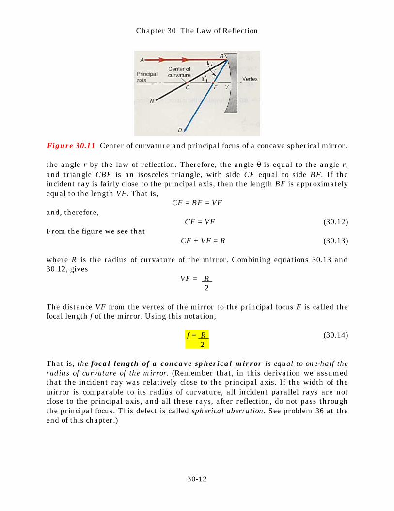
Figure 30.11 Center of curvature and principal focus of a concave spherical mirror.
the angle r by the law of reflection. Therefore, the angle θ is equal to the angle r,and triangle CBF is an isosceles triangle, with side CF equal to side BF. If theincident ray is fairly close to the principal axis, then the length BF is approximatelyequal to the length VF. That is,
CF = BF = VFand, therefore,
CF = VF (30.12)From the figure we see that
CF + VF = R (30.13)
where R is the radius of curvature of the mirror. Combining equations 30.13 and30.12, gives
VF = R 2
The distance VF from the vertex of the mirror to the principal focus F is called thefocal length f of the mirror. Using this notation,
f = R (30.14) 2
That is, the focal length of a concave spherical mirror is equal to one-half theradius of curvature of the mirror. (Remember that, in this derivation we assumedthat the incident ray was relatively close to the principal axis. If the width of themirror is comparable to its radius of curvature, all incident parallel rays are notclose to the principal axis, and all these rays, after reflection, do not pass throughthe principal focus. This defect is called spherical aberration. See problem 36 at theend of this chapter.)
Chapter 30 The Law of Reflection
30-12
Example 30.3
The focal length of a spherical mirror. To what radius should you grind a sphericalconcave mirror in order to get a focal length of 10.0 cm?
Solution
The radius of the mirror, found from equation 30.14, is
R = 2f = 2(10.0 cm) = 20.0 cm
To go to this Interactive Example click on this sentence.
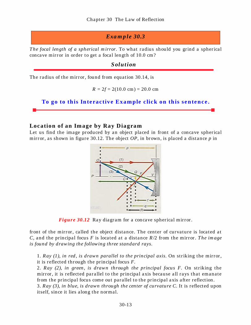
Location of an Image by Ray DiagramLet us find the image produced by an object placed in front of a concave sphericalmirror, as shown in figure 30.12. The object OP, in brown, is placed a distance p in
Figure 30.12 Ray diagram for a concave spherical mirror.
front of the mirror, called the object distance. The center of curvature is located atC, and the principal focus F is located at a distance R/2 from the mirror. The imageis found by drawing the following three standard rays.
1. Ray (1), in red, is drawn parallel to the principal axis. On striking the mirror,it is reflected through the principal focus F.2. Ray (2), in green, is drawn through the principal focus F. On striking themirror, it is reflected parallel to the principal axis because all rays that emanatefrom the principal focus come out parallel to the principal axis after reflection.3. Ray (3), in blue, is drawn through the center of curvature C. It is reflected uponitself, since it lies along the normal.
Chapter 30 The Law of Reflection
30-13
The intersection of these three rays defines the top of the image, whereas theprincipal axis defines the bottom of the image. The image QI is shown in yellow inthe figure. The distance of this image from the vertex of the mirror is called theimage distance and is designated by the letter q. The image is real, since the rays oflight actually converge at this point. If we were to place a screen at this point, wewould see a sharp image of the original object located at this point. Note that theimage is inverted.
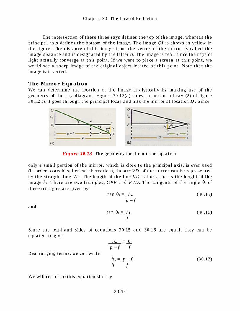
The Mirror EquationWe can determine the location of the image analytically by making use of thegeometry of the ray diagram. Figure 30.13(a) shows a portion of ray (2) of figure30.12 as it goes through the principal focus and hits the mirror at location D’. Since
Figure 30.13 The geometry for the mirror equation.
only a small portion of the mirror, which is close to the principal axis, is ever used(in order to avoid spherical aberration), the arc VD’ of the mirror can be representedby the straight line VD. The length of the line VD is the same as the height of theimage hi. There are two triangles, OPF and FVD. The tangents of the angle θ1 ofthese triangles are given by
tan θ1 = ho (30.15) p − f
andtan θ1 = hi (30.16)
f
Since the left-hand sides of equations 30.15 and 30.16 are equal, they can beequated, to give
ho = hi
p − f f Rearranging terms, we can write
ho = p − f (30.17) hi f
We will return to this equation shortly.
Chapter 30 The Law of Reflection
30-14

Now consider the ray from the object that goes through the vertex V of themirror, figure 30.13(b). This ray is reflected and intersects the image at the point I.Because V lies along the principal axis, which is normal to the mirror at V, theangle of incidence OVP is equal to the angle of reflection IVQ by the law of thereflection. Let us call these angles θ2. From figure 30.13(b) we can see that
tan θ2 = ho
pand
tan θ2 = hi
q
Since the left-hand side of these two equations are equal they can be equated, togive
ho = hi
p q Rearranging terms,
ho = p (30.18) hi q
Since the left-hand side of equation 30.17 is equal to the left-hand side of equation30.18, they can be equated to give
p = p − f = p − 1 q f f Dividing each term by p, gives
1 = 1 − 1 (30.19) q f p
Rearranging terms, the equation becomes
1 = 1 + 1 (30.20) f p q
Equation 30.20 is called the mirror equation, and it shows the relation between thefocal length f of the mirror, the object distance p, and the image distance q.
Example 30.4
Finding the image for a concave spherical mirror. An object 5.00 cm high is placed30.0 cm in front of a concave spherical mirror of 10.0-cm focal length. Where is theimage located?
Chapter 30 The Law of Reflection
30-15

Solution
The location of the image, found from equation 30.19, is
1 = 1 − 1 q f p = 1 − 1 10.0 cm 30.0 cm
= 0.100 cm−1 − 0.0333 cm−1 = 0.0667 cm−1
andq = 15.0 cm
To go to this Interactive Example click on this sentence.
MagnificationAnother important relationship in an optical system can be obtained by defining thelinear magnification M of the mirror as the ratio of the size of the image hi to thesize of the object ho. That is,
M = hi ho
Thus, the magnification tells how much larger the image is than the object. Usingequation 30.18, we can rewrite this as
M = hi = − q (30.21) ho p
When we know the magnification M, we find the height of the image hi fromequation 30.21 as
hi = Mho (30.22)
The minus sign in equation 30.21 is one of convention. Notice from example30.4 and the ray diagram of figure 30.12, that a positive value of q gives an invertedimage. The minus sign in equation 30.21 thus signifies that when M is negative, theimage is inverted. We will see a little later that it is possible to have a negativevalue of q. That case gives us a positive value for M, and thus signifies that theimage is erect or right side up.
Chapter 30 The Law of Reflection
30-16
Example 30.5
The magnification of a spherical mirror. Determine the magnification and size of theimage in example 30.4.
Solution
The magnification of the system, found from equation 30.21, is
M = − q = −15.0 cm = −0.500 p 30.0 cm
The height of the image, found from equation 30.22, is
hi = Mho
= (−0.500)(5.00 cm)= −2.50 cm
The minus sign indicates that the image is inverted.
To go to this Interactive Example click on this sentence.
To summarize the possible cases of magnification:if M > 1 the image is enlargedif M = 1 the image is trueif M < 1 the image is reducedif M > 0 the image is erectif M < 0 the image is inverted.
Some Special Cases of the Concave Spherical MirrorA great deal of insight into the concave mirror can be obtained by first placing theobject at infinity (or at least a very far distance away from the mirror). Now wemove the object in toward the mirror and observe what happens to the image.
Case 1: The Object Is Located at InfinityWhen the object is at a very large distance from the mirror, the object distance p iseffectively infinite. The location of the image, found from equation 30.19, is
1 = 1 − 1 q f p
Chapter 30 The Law of Reflection
30-17

= 1 − 1 f ∞But 1/∞ is equal to zero. Therefore,
1 = 1 q fand
q = f (30.23)
Equation 30.23 says that when the object is located at infinity the image is locatedat the principal focus. The ray diagram for this case was shown in figure 30.10. Themagnification is M = q/p = q/∞ = 0 for this case, showing that all the rays convergeto a point and the height of the image is hi = 0.
Case 2: The Object Is between Infinity and the Center of CurvatureThis is a general case, the ray diagram of which was shown in figure 30.12. Theimage location is found from equation 30.19 when the appropriate values of f and pare introduced. Note from figure 30.12 that the image, which was at F when theobject was at infinity, has now moved to the left of F away from the mirror. Theimage is inverted and real and the magnification (M = q/p) is less than 1 because qis less than p. The image is therefore smaller than the object, but still greater thanits value of zero, when the image was at the focal point F.
Case 3: The Object Is Located at the Center of Curvature of the MirrorWhen the object is placed at the center of curvature of the mirror, the objectdistance p is equal to the radius of curvature R, which is equal to 2f. The image isfound from
1 = 1 − 1 q f p
= 1 − 1 = 1 − 1 = 1 f R f 2f 2f and
q = 2f = R (30.24)
Equation 30.24 says that when the object is located at the center of curvature of themirror, the image is also located there. Figure 30.14 shows the ray diagram for thiscase. Because q = p for this case, the magnification becomes
M = − q = − p = −1 p p
The minus sign for the value of M indicates that the image is inverted, as seen infigure 30.14. The absolute value of the magnification is equal to 1, hence, the heightof the image hi is the same size as the height of the object ho. Again note that as the
Chapter 30 The Law of Reflection
30-18
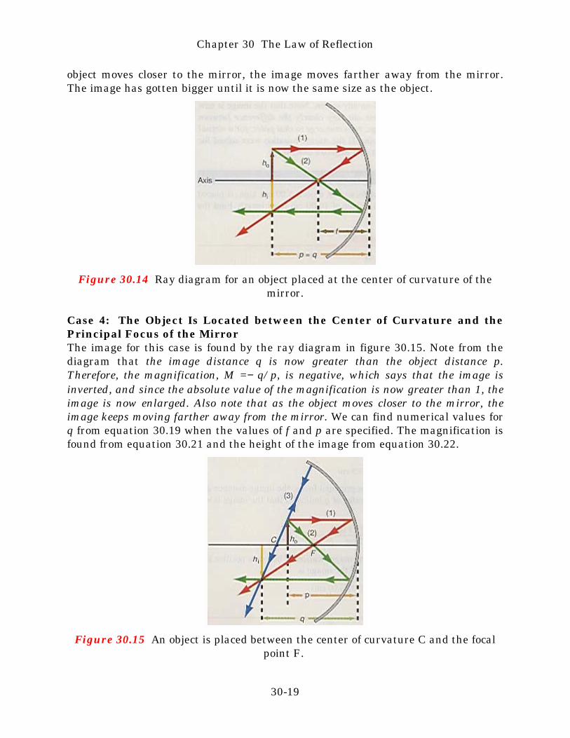
object moves closer to the mirror, the image moves farther away from the mirror.The image has gotten bigger until it is now the same size as the object.
Figure 30.14 Ray diagram for an object placed at the center of curvature of themirror.
Case 4: The Object Is Located between the Center of Curvature and thePrincipal Focus of the MirrorThe image for this case is found by the ray diagram in figure 30.15. Note from thediagram that the image distance q is now greater than the object distance p.Therefore, the magnification, M =− q/p, is negative, which says that the image isinverted, and since the absolute value of the magnification is now greater than 1, theimage is now enlarged. Also note that as the object moves closer to the mirror, theimage keeps moving farther away from the mirror. We can find numerical values forq from equation 30.19 when the values of f and p are specified. The magnification isfound from equation 30.21 and the height of the image from equation 30.22.
Figure 30.15 An object is placed between the center of curvature C and the focalpoint F.
Chapter 30 The Law of Reflection
30-19
Case 5: The Object Is Located at the Principal FocusWhen the object is located at the principal focus, p = f, and the image, found fromequation 30.19, is
1 = 1 − 1 = 1 − 1 = 0 q f p f f
The only way for 1/q to equal zero is for q to become infinite. Therefore,
q = ∞
That is, when the object moves into the principal focus, the image moves out toinfinity.
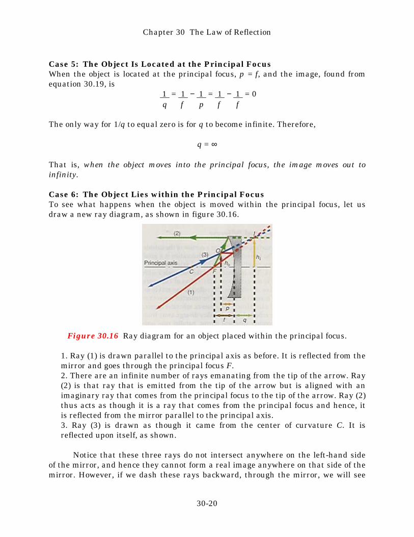
Case 6: The Object Lies within the Principal FocusTo see what happens when the object is moved within the principal focus, let usdraw a new ray diagram, as shown in figure 30.16.
Figure 30.16 Ray diagram for an object placed within the principal focus.
1. Ray (1) is drawn parallel to the principal axis as before. It is reflected from themirror and goes through the principal focus F.2. There are an infinite number of rays emanating from the tip of the arrow. Ray(2) is that ray that is emitted from the tip of the arrow but is aligned with animaginary ray that comes from the principal focus to the tip of the arrow. Ray (2)thus acts as though it is a ray that comes from the principal focus and hence, itis reflected from the mirror parallel to the principal axis.3. Ray (3) is drawn as though it came from the center of curvature C. It isreflected upon itself, as shown.
Notice that these three rays do not intersect anywhere on the left-hand sideof the mirror, and hence they cannot form a real image anywhere on that side of themirror. However, if we dash these rays backward, through the mirror, we will see
Chapter 30 The Law of Reflection
30-20
that they do intersect on the right-hand side of the mirror. When we look into themirror, it will appear as though these three rays are emanating from that point onthe other side of the mirror. This point, therefore, locates the image; but we now callit a virtual image, since light rays only appear to come from that point. The image isnot real; it cannot be projected on any screen. Note that the image is now erect andenlarged. This example points out very clearly the difference between real and virtualimages. For a real image, rays converge to that point; for a virtual image, raysdiverge away from that point. If the mirror equation were solved for the imagedistance q, it would come out as a negative quantity.
Example 30.6
An object is placed within the principal focus. An object, 5.00 cm high, is placed 7.00cm in front of a concave spherical mirror of 10.00-cm focal length. Find the locationof its image and its final size.
Solution
The image, found from equation 30.19, is
1 = 1 − 1 = 1 − 1 q f p 10.00 cm 7.00 cm
= 0.1000 cm−1 − 0.1428 cm−1 = −0.0428 cm−1
andq = −23.3 cm
Notice that for the object placed within the principal focus, the image distance q isnegative, as stated previously. A negative value of q indicates that the image isvirtual. The magnification is
M = − q = − (−23.3 cm) = +3.33 p 7 cm
Note in this case that since q is negative, the magnification M becomes positive andhence, the image is erect. The final height of the image is
hi = Mho = (3.33)(5.00 cm)= 16.7 cm
To go to this Interactive Example click on this sentence.
Chapter 30 The Law of Reflection
30-21
A practical example of a concave spherical mirror used in this way is found ina man’s shaving mirror or a woman’s make-up mirror. The focal length is designedsuch that when you place your head in front of the mirror, it is located within theprincipal focus of the mirror. You therefore see your face erect and enlarged.
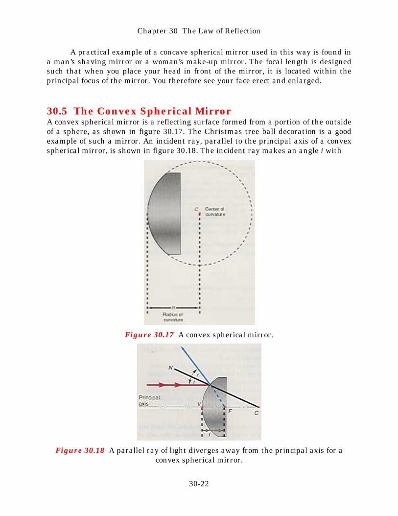
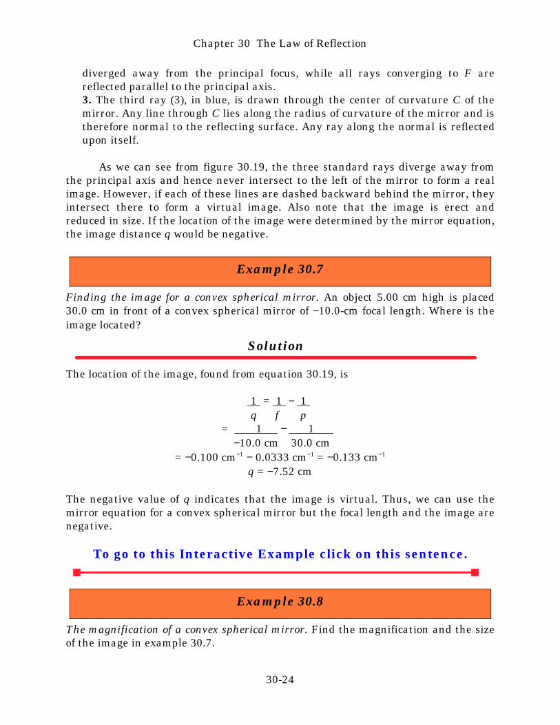
30.5 The Convex Spherical MirrorA convex spherical mirror is a reflecting surface formed from a portion of the outsideof a sphere, as shown in figure 30.17. The Christmas tree ball decoration is a goodexample of such a mirror. An incident ray, parallel to the principal axis of a convexspherical mirror, is shown in figure 30.18. The incident ray makes an angle i with
Figure 30.17 A convex spherical mirror.
Figure 30.18 A parallel ray of light diverges away from the principal axis for aconvex spherical mirror.
Chapter 30 The Law of Reflection
30-22

the normal to the surface. The normal is the extension of the radius of curvaturefrom the center of curvature C. By the law of reflection, the reflected ray makes anangle r with the normal and the angle r is equal to angle i. The reflected ray is thusseen to diverge away from the principal axis. Hence, for a convex spherical mirror,all rays parallel to the principal axis are reflected such that they diverge away fromthe principal axis. (Recall that for a concave spherical mirror, parallel raysconverged to the principal axis.) If the reflected ray is dashed backward, itintersects the principal axis at the point F. All rays parallel to the principal axisintersect at this same point, which is called the principal focus of the convexspherical mirror. Thus, rays that are parallel to the principal axis appear to divergefrom the principal focus F. The distance from V, the vertex of the mirror, to F iscalled the focal length f of the mirror. The radius of curvature of the convexspherical mirror is considered to be negative because the center of curvature is onthe other side of the mirror. (Recall that for the concave mirror, the center ofcurvature was on the same side as the reflecting surface and the radius of curvaturewas positive.) Since the radius of curvature is negative for the convex sphericalmirror, the focal length f, which is equal to one-half the radius of curvature, is alsonegative. With this convention, the mirror equation, equation 30.20, is applicable toeither type of mirror.
Location of an Image by a Ray DiagramThe location of the image for a convex spherical mirror is found by drawing thethree standard rays in the ray diagram shown in figure 30.19.
Figure 30.19 Ray diagram for a convex spherical mirror.
1. The first ray (1), in red, is drawn parallel to the principal axis and is reflectedfrom the mirror as if it came from the principal focus F.2. The second ray (2), in green, is drawn straight toward the principal focus F. Itis reflected parallel to the principal axis before it can get to the principal focus.This is another example of the principle of reversibility; all parallel rays are
Chapter 30 The Law of Reflection
30-23
diverged away from the principal focus, while all rays converging to F arereflected parallel to the principal axis.3. The third ray (3), in blue, is drawn through the center of curvature C of themirror. Any line through C lies along the radius of curvature of the mirror and istherefore normal to the reflecting surface. Any ray along the normal is reflectedupon itself.
As we can see from figure 30.19, the three standard rays diverge away fromthe principal axis and hence never intersect to the left of the mirror to form a realimage. However, if each of these lines are dashed backward behind the mirror, theyintersect there to form a virtual image. Also note that the image is erect andreduced in size. If the location of the image were determined by the mirror equation,the image distance q would be negative.
Example 30.7
Finding the image for a convex spherical mirror. An object 5.00 cm high is placed30.0 cm in front of a convex spherical mirror of −10.0-cm focal length. Where is theimage located?
Solution
The location of the image, found from equation 30.19, is
1 = 1 − 1 q f p
= 1 − 1 −10.0 cm 30.0 cm
= −0.100 cm−1 − 0.0333 cm−1 = −0.133 cm−1
q = −7.52 cm
The negative value of q indicates that the image is virtual. Thus, we can use themirror equation for a convex spherical mirror but the focal length and the image arenegative.
To go to this Interactive Example click on this sentence.
Example 30.8
The magnification of a convex spherical mirror. Find the magnification and the sizeof the image in example 30.7.
Chapter 30 The Law of Reflection
30-24
Solution
The magnification isM = − q = −(−7.52 cm) = +0.251
p 30.0 cm
Note that M is positive indicating an erect image. The size of the image is
hi = Mho = (0.251)(5.00 cm)= 1.26 cm
To go to this Interactive Example click on this sentence.
If we consider the different possible cases of moving the object from infinitytoward the mirror, as in the case of the concave mirror, we find for a convexspherical mirror that for a real object, the image is always virtual, erect, and reducedin size.
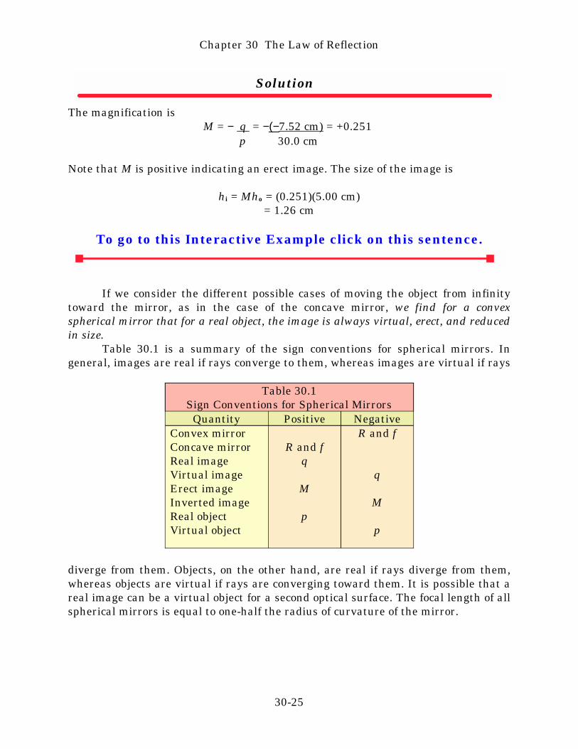
Table 30.1 is a summary of the sign conventions for spherical mirrors. Ingeneral, images are real if rays converge to them, whereas images are virtual if rays
R and f
q
M
p
R and fq
M
p
Convex mirrorConcave mirrorReal imageVirtual imageErect imageInverted imageReal objectVirtual object
NegativePositiveQuantity
Table 30.1Sign Conventions for Spherical Mirrors
diverge from them. Objects, on the other hand, are real if rays diverge from them,whereas objects are virtual if rays are converging toward them. It is possible that areal image can be a virtual object for a second optical surface. The focal length of allspherical mirrors is equal to one-half the radius of curvature of the mirror.
Chapter 30 The Law of Reflection
30-25

The Language of Physics
OpticsThe study of light (p. ).
Wave frontA line connecting points all having the same phase of vibration. Wave fronts from apoint source of light are spherical. Far away from the source, the waves appearplane (p. ).
Geometrical opticsThe analysis of an optical system in terms of light rays that travel in straight lines(p. ).
Wave optics or physical opticsThe analysis of an optical system in terms of the wave nature of light (p. ).
Quantum opticsThe study of light in terms of little bundles of electromagnetic energy, calledphotons (p. ).
Huygens’ principleEach point on a wave front may be considered as a source of secondary sphericalwavelets. These secondary wavelets propagate at the same speed as the initialwave. The new position of the wave front at a later time is found by drawing thetangent to all of these secondary wavelets at the later time (p. ).
The law of reflectionThe angle of incidence is equal to the angle of reflection. The incident ray, thenormal, and the reflected ray all lie in the same plane (p. ).
Real imageAn image formed by rays converging to a point. A real image can be projected onto ascreen (p. ).
Virtual imageAn image formed by rays diverging from a point. A virtual image cannot beprojected onto a screen (p. ).
Optical imageA reproduction of an object by an optical system. To describe an image three wordsare necessary: its nature (real or virtual), its orientation (erect, inverted, orperverted), and its size (enlarged, true, or reduced) (p. ).
Chapter 30 The Law of Reflection
30-26
Spherical mirrorA reflecting surface whose radius of curvature is the radius of the sphere fromwhich the mirror is formed. A plane mirror is a special case of a spherical mirrorwith a radius of curvature that is infinite (p. ).
Principle of reversibilityIf a ray traces a certain path through an optical system in one direction, then a raysent backward through the system along the same path, traverses the original pathand exits along the line that the original ray entered (p. ).
Focal lengthThe point where all rays parallel and close to the principal axis converge. The focallength of a concave spherical mirror is equal to one-half of its radius of curvature(p. ).
MagnificationThe ratio of the size of an image to the size of its object (p. ).
Summary of Important Equations
The wavelength, frequency, and speed of light λν = c (30.1)
Law of reflection i = r (30.4)
Focal length of a spherical mirror f = R/2 (30.14)
Mirror equation 1 = 1 + 1 (30.20) f p q
Magnification M = hi = − q (30.21) ho p
Height of image hi = Mho (30.22)
Questions for Chapter 30
1. If you hold this textbook in front of a plane mirror the letters will all bereversed from left to right. Why are they not also reversed from top to bottom?
2. Explain the difference between a real image and a virtual image.*3. How can Huygens’ principle be justified?
Chapter 30 The Law of Reflection
30-27

4. What effect does changing the object distance have on the size of an imagein a plane mirror?
5. It is easy to see an image formed by the reflection of light from a smoothsurface such as a mirror. What type of reflection would occur if the surface wererough?
6. In the barbershop, mirrors are placed on the wall in front and behind thecustomer. How are the mirrors arranged so that the customer can see the back ofhis head?
7. Explain the process of formation of an image for a concave spherical mirroras the object starts at infinity and moves toward the mirror. What happens to themagnification?
8. You would like to place a mirror in the corner of your store so that you cansee every thing going on in the store. What type of mirror should you use?
*9. Using Huygens’ principle, describe what happens to a wave front of lightwhen it hits the edge of a surface.
*10. Two plane mirrors are placed at 900 to each other. Explain how, whenyou look directly toward the vertex of the two mirrors, you see yourself as others seeyou. That is, left is left and right is right. Draw a diagram to help in the analysis.
11. How can you make a toy periscope with two plane mirrors?12. The Hubble Space Telescope, launched by NASA in May 1990 to take
pictures of the universe never seen before, developed a serious flaw. The telescopewas not able to focus properly. The cause of the problem was spherical aberration ofeither the primary or secondary mirror. What is spherical aberration and how doesit affect the telescope?
The 2.4-m main mirror from the Hubble Space Telescope.
Problems for Chapter 30
Chapter 30 The Law of Reflection
30-28
30.1 Light as an Electromagnetic Wave1. What is the frequency of (a) violet light of 380.0-nm wavelength and (b) red
light of 720.0-nm wavelength?2. What is the wavelength of the electromagnetic radiation of the following
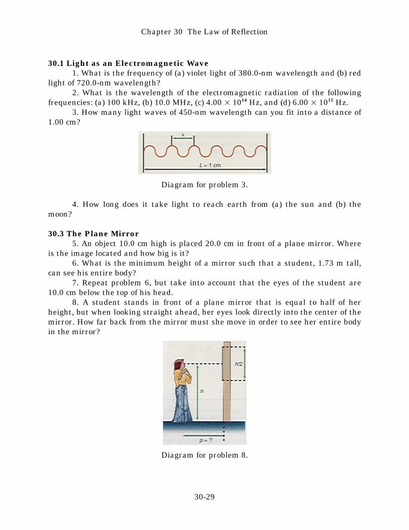
frequencies: (a) 100 kHz, (b) 10.0 MHz, (c) 4.00 × 10¹⁴ Hz, and (d) 6.00 × 10¹⁵ Hz.3. How many light waves of 450-nm wavelength can you fit into a distance of
1.00 cm?
Diagram for problem 3.
4. How long does it take light to reach earth from (a) the sun and (b) themoon?
30.3 The Plane Mirror5. An object 10.0 cm high is placed 20.0 cm in front of a plane mirror. Where
is the image located and how big is it?6. What is the minimum height of a mirror such that a student, 1.73 m tall,
can see his entire body?7. Repeat problem 6, but take into account that the eyes of the student are
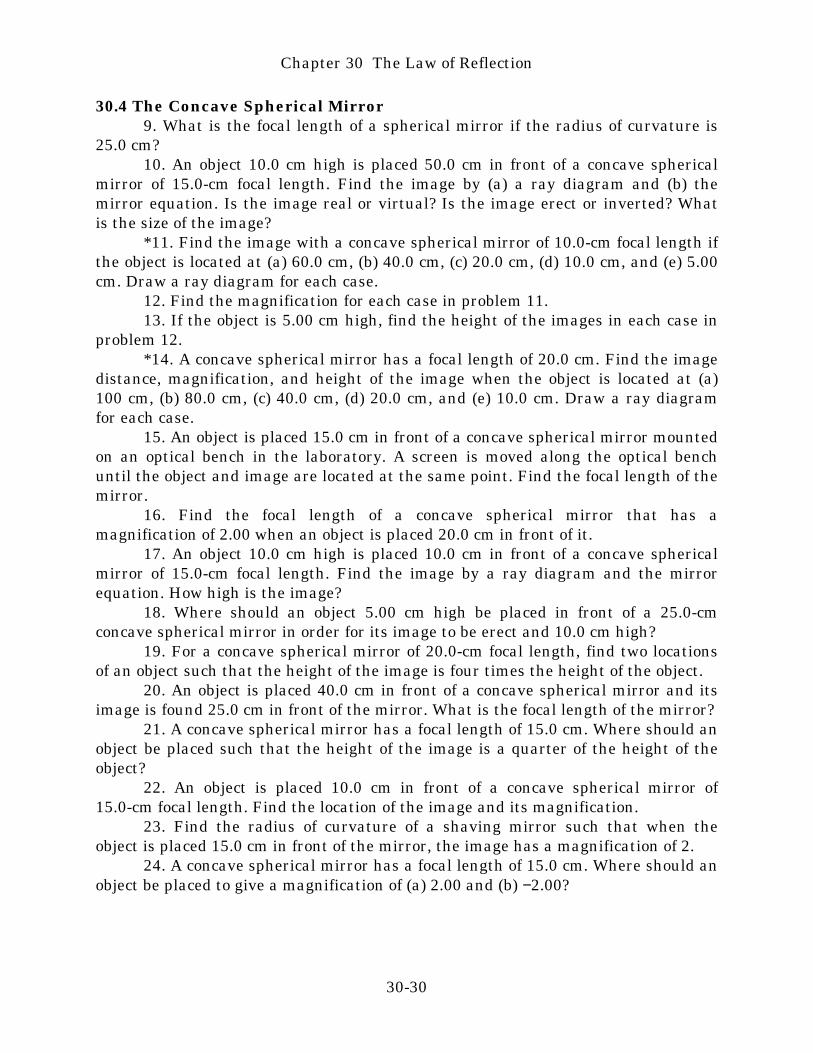
10.0 cm below the top of his head.8. A student stands in front of a plane mirror that is equal to half of her
height, but when looking straight ahead, her eyes look directly into the center of themirror. How far back from the mirror must she move in order to see her entire bodyin the mirror?
Diagram for problem 8.
Chapter 30 The Law of Reflection
30-29
30.4 The Concave Spherical Mirror9. What is the focal length of a spherical mirror if the radius of curvature is
25.0 cm?10. An object 10.0 cm high is placed 50.0 cm in front of a concave spherical
mirror of 15.0-cm focal length. Find the image by (a) a ray diagram and (b) themirror equation. Is the image real or virtual? Is the image erect or inverted? Whatis the size of the image?
*11. Find the image with a concave spherical mirror of 10.0-cm focal length ifthe object is located at (a) 60.0 cm, (b) 40.0 cm, (c) 20.0 cm, (d) 10.0 cm, and (e) 5.00cm. Draw a ray diagram for each case.
12. Find the magnification for each case in problem 11.13. If the object is 5.00 cm high, find the height of the images in each case in
problem 12.*14. A concave spherical mirror has a focal length of 20.0 cm. Find the image
distance, magnification, and height of the image when the object is located at (a)100 cm, (b) 80.0 cm, (c) 40.0 cm, (d) 20.0 cm, and (e) 10.0 cm. Draw a ray diagramfor each case.
15. An object is placed 15.0 cm in front of a concave spherical mirror mountedon an optical bench in the laboratory. A screen is moved along the optical benchuntil the object and image are located at the same point. Find the focal length of themirror.
16. Find the focal length of a concave spherical mirror that has amagnification of 2.00 when an object is placed 20.0 cm in front of it.
17. An object 10.0 cm high is placed 10.0 cm in front of a concave sphericalmirror of 15.0-cm focal length. Find the image by a ray diagram and the mirrorequation. How high is the image?
18. Where should an object 5.00 cm high be placed in front of a 25.0-cmconcave spherical mirror in order for its image to be erect and 10.0 cm high?
19. For a concave spherical mirror of 20.0-cm focal length, find two locationsof an object such that the height of the image is four times the height of the object.
20. An object is placed 40.0 cm in front of a concave spherical mirror and itsimage is found 25.0 cm in front of the mirror. What is the focal length of the mirror?
21. A concave spherical mirror has a focal length of 15.0 cm. Where should anobject be placed such that the height of the image is a quarter of the height of theobject?
22. An object is placed 10.0 cm in front of a concave spherical mirror of15.0-cm focal length. Find the location of the image and its magnification.
23. Find the radius of curvature of a shaving mirror such that when theobject is placed 15.0 cm in front of the mirror, the image has a magnification of 2.
24. A concave spherical mirror has a focal length of 15.0 cm. Where should anobject be placed to give a magnification of (a) 2.00 and (b) −2.00?
Chapter 30 The Law of Reflection
30-30

30.5 The Convex Spherical Mirror25. A reflecting Christmas tree ball has a diameter of 8.00 cm. What is the
focal length of such an ornament?26. An object 10.0 cm high is placed 30.0 cm in front of a convex spherical
mirror of −10.0-cm focal length. Find the image by a ray diagram and the mirrorequation. Find the height of the image.
*27. Find the image with a convex spherical mirror of 10.0-cm focal length ifthe object is located at (a) 60.0 cm, (b) 40.0 cm, (c) 20.0 cm, (d) 10.0 cm, and (e) 5.00cm. Draw a ray diagram for each case.
28. An object is 12.0 cm in front of a convex spherical mirror, and the image isformed 24.0 cm behind the mirror. Find the focal length of the mirror.
29. Where should an object be placed in front of a convex spherical mirror of15.5-cm focal length in order to get a virtual image with a magnification of one-half?
30. The distance between a real object and a virtual image formed by aconvex spherical mirror is 50.0 cm. If the focal length of the mirror is f = −25.0 cm,find the two possible positions for the mirror.
Additional Problems*31. A plane mirror is rotated through an angle θ. Show that the reflected ray
will always be rotated through an angle of 2θ.32. Show that a plane mirror is a special case of a concave spherical mirror
whose radius of curvature is infinite. What does the mirror equation reduce to?*33. Two mirrors make an angle of 900 with each other. Show that if a ray of
light is incident on the first mirror at an angle of incidence i, the reflected ray fromthe second mirror makes an angle of reflection of 900 − i.
Diagram for problem 33. Diagram for problem 34.
*34. Two mirrors make an angle of θ with each other. Show that if a ray oflight is incident on the first mirror at an angle of incidence i, the reflected ray from
Chapter 30 The Law of Reflection
30-31
the second mirror makes an angle of reflection of θ − i.*35. Show that when an object is placed in front of a concave spherical mirror
of focal length f and experiences a magnification M, the image is located at theimage distance given by
q = f(1 − M)
36. An object is placed 25.0 cm in front of a concave spherical mirror. Theimage is found to be a quarter of the size of the object. Find the focal length of themirror.
37. An object is magnified by a factor of 2 when it is placed 15.0 cm in front ofa concave spherical mirror. Find the radius of curvature of the mirror.
38. A dentist uses a small concave spherical mirror to see a cavity in a tooth.If the image is to be magnified by a factor of 3 when the tooth is 2.50 cm in front ofthe mirror, what should be the focal length of such a mirror?
39. An optical system is designed so that an object for a convex sphericalmirror of focal length f = −15.0 cm is 20.0 cm behind the mirror (a virtual object).Find the image distance and the magnification, and determine whether the image isreal or virtual, erect or inverted.
40. Repeat problem 39 with an object located only 5.00 cm behind the mirror.*41. Use a compass to draw a concave spherical mirror 10.0 cm in radius.
Draw light rays parallel to the principal axis at every 1.00 cm above and below theprincipal axis. Using a protractor, carefully measure the angles of incidence andreflection for each of these rays, and see where they cross the principal axis. Whatdoes this tell you about the underlying assumption in the mirror equation? Howdoes this relate to spherical aberration of the mirror?
*42. Draw a graph of the image distance q as a function of the object distancep for a concave spherical mirror of focal length 10.0 cm. Show the regions thatrepresent the concave mirror and the convex mirror. Show the regions where theimages are real and where they are virtual.
*43. Draw a graph of the magnification M of a concave spherical mirror as afunction of the object distance p. Repeat for a convex spherical mirror.
Interactive Tutorials44. Light as a wave. A tower on earth transmits a laser beam of frequency f =
5.00 × 10¹⁴ Hz to a spaceship at a distance x = 7.40 × 10¹¹ m. Calculate (a) thewavelength λ of the laser beam and (b) the time t for the beam to reach thespaceship.
45. Spherical mirror with known radius of curvature. An object of height ho =3.00 cm is placed at the object distance p = 10.0 cm of a spherical mirror of radius ofcurvature R = 8.00 cm. Find (a) the focal length f of the mirror, (b) the imagedistance q, (c) the magnification M, and (d) the height hi of the resulting image.
46. Spherical mirror with known focal length. An object of height ho = 8.50 cmis placed at the object distance p = 35.0 cm of a spherical mirror of focal length f =
Chapter 30 The Law of Reflection
30-32
15.0 cm. Find (a) the radius of curvature R of the mirror, (b) the image distance q,(c) the magnification M, and (d) the height hi of the resulting image.
To go to these Interactive Tutorials click on this sentence.
To go to another chapter, return to the table of contents byclicking on this sentence.
Chapter 30 The Law of Reflection
30-33